

Page 1
Solera® Universal Hardware
Manual Awning to
Solera Classic Manual Awning
(For Aftermarket Application)
Solera®
Universal
Hardware
Manual Awning to Solera®
Classic Manual Awning
(For Aftermarket Applications)
Table of Contents
Introduction ............................................ 2
System Information .................................... 2
Additional Information Sources ........................ 2
Safety Information ..................................... 2
Parts List ................................................ 2
Preparation ............................................. 3
Resources Required ................................... 3
Conversion ............................................. 3
Dometic Manual Awning to Solera® Classic Manual
Awning ................................................. 3
Carefree Manual Awning to Solera® Classic Manual
Awning ................................................. 7
Operation ............................................. 12
Extending the Awning ............................... 12
Optional Carport Position ............................ 13
Retracting the Awning ............................... 13
Maintenance ......................................... 13
Fabric Care .......................................... 13
Troubleshooting ...................................... 14
lippertcomponents.com 574-537-8900 Rev: 11.17 - Solera® Universal Hardware Conversion
1
Page 2

Solera® Universal Hardware
Manual Awning to
Solera Classic Manual Awning
(For Aftermarket Application)
Introduction
System Information
The Solera® Classic Manual Awning is designed for use on
most recreational vehicle units and is available in a variety
of sizes to t even the largest unit.
NOTE: The LCI Solera® Universal Hardware kit for a
manual to manual conversion will ONLY t Dometic and
Carefree awnings.
Additional Information Sources
Additional information about this product can be obtained
from www.lci1.com/support or by using the myLCI app.
Replacement components can be ordered from https://
store.lci1.com/ or by using the myLCI app. The myLCI app
is available for free on iTunes® for iPhone® and iPad® and
also on Google Play™ for Android™ users.
iTunes, iPhone, and iPad are registered trademarks of
Apple Inc.
Google Play and Android are trademarks of Google Inc.
Safety Information
Warning, Caution and Danger symbols indicate that an
installation procedure has a safety risk involved and may
cause death, serious injury or property damage if not
performed safely and within the parameters set forth in this
manual.
Parts List
Universal Kit No. Description
43 4717
43 4718
Solera Classic Standard Kit - Black
Solera Classic Standard Kit - White
MOVING PARTS CAN PINCH, CRUSH OR CUT. KEEP
CLEAR AND USE CAUTION.
Manual awnings that contain springs use tension for ease
of operation and can be harmful to the end user should the
stored tension come unbound. Cotter pins, travel locks and
cam locks are installed and MUST be used to contain the
tension when the system is being serviced.
FAILURE TO USE THE INSTALLED SAFETY FEATURES
MAY RESULT IN DEATH, SERIOUS INJURY, DAMAGE TO
THE UNIT AND/OR VOIDING A WARRANTY.
lippertcomponents.com 574-537-8900 Rev: 11.17 - Solera® Universal Hardware Conversion
2
Page 3

Solera® Universal Hardware
Manual Awning to
Solera Classic Manual Awning
(For Aftermarket Application)
Preparation
Resources Required
• Additional Qualied Assistant
• Cordless or Electric Drill or Screw Gun
• Appropriate Drive and Drill Bits
• Socket Wrench
• 3/8” Socket
• Rivet Gun
• Locking Pliers
• Ladder
• Silicone Sealant
• Non-permanent Method of Marking
Conversion
Dometic Manual Awning to Solera Classic Manual Awning
NOTE: All screws supporting the awning assembly MUST
have a backer within the structure of the wall of the unit.
NOTE: Silicone sealant MUST be used on all screws and
holes to prevent water from inltrating the unit.
NOTE: This manual will refer to the “drive side” and “idler
side” throughout for various instructions. The “drive side” is
the right hand side of the awning when facing the awning
from the exterior of the unit. The “idler side” is the left
hand side of the awning when facing the awning from the
exterior of the unit.
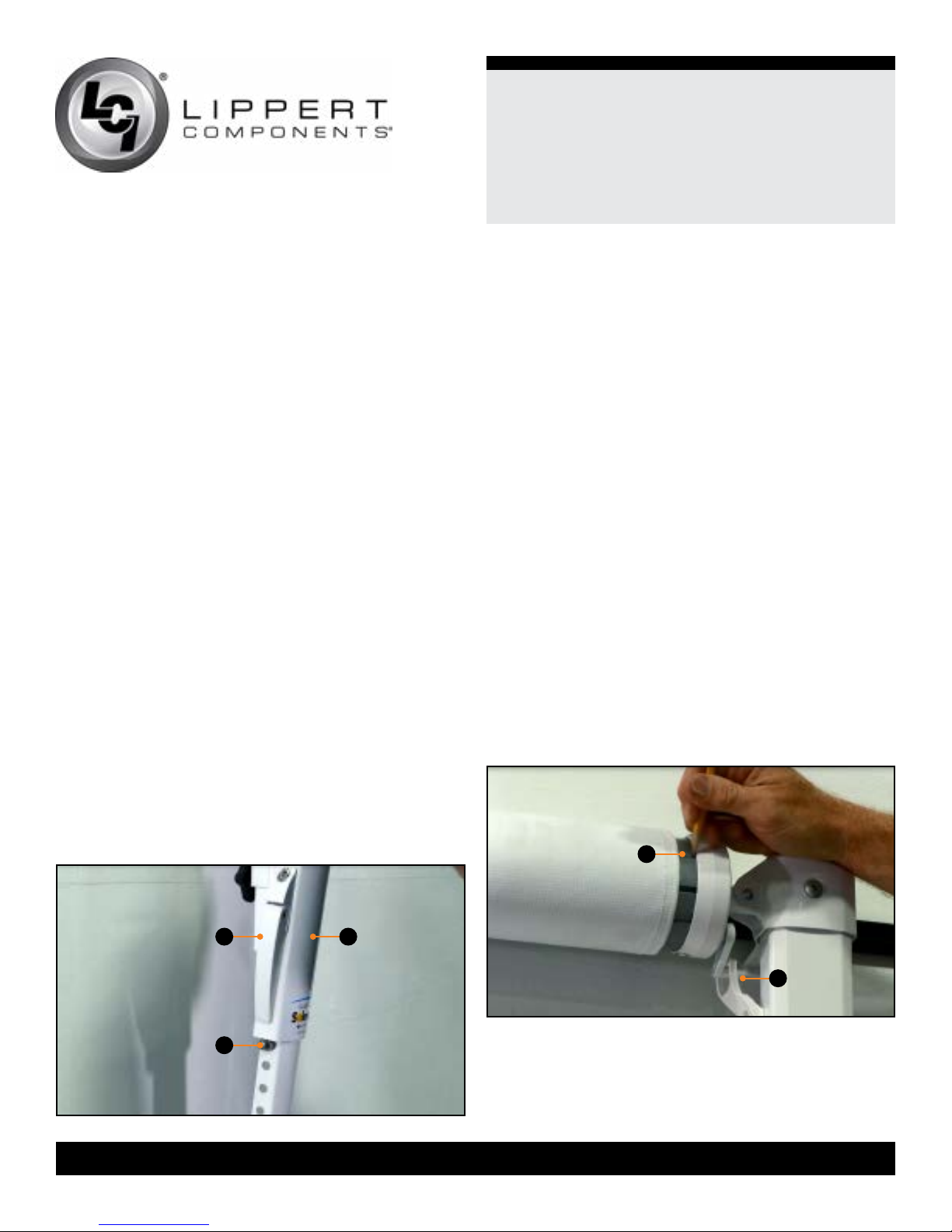
1. With the awning fully retracted, make a non-permanent
marking on the roll tube (Fig.1A) indicating the position of
the cam lock (Fig.1B).
NOTE: This mark will assist in positioning the cam lock on
the Solera Classic Manual Awning.
lippertcomponents.com 574-537-8900 Rev: 11.17 - Solera® Universal Hardware Conversion
A B
Fig.1
3
Page 4

Solera® Universal Hardware
Manual Awning to
Solera Classic Manual Awning
(For Aftermarket Application)
2. Unlock the travel locks, move the cam lock to the roll out
position and fully extend the awning.
3. Insert a cotter pin (Fig.2C) into the end cap (Fig.2A) at
each end of the awning.
4. Pull the idler and drive side rafter arms (Fig.2B) up and
lock it into the head of the support arm (Fig.2D).
NOTE: Be sure to tighten the tension knob (Fig.3B) on the idler
and drive rafter arms before moving on.
A
A B
B
C D
Fig.2
Fig.3
6. Separate the drive head from the support arm and
secure the support arm to the unit in the travel position.
7. With an assistant holding the roll tube, rmly take hold of
the drive head with a pair of locking pliers (Fig.5). Remove
the cotter pin from the end cap and move the cam lock to
the roll up position.
NOTE: Padding the locking pliers will prevent scratching
components.
Fig.5
5. On the drive side of the awning, release the rafter arm.
With the rafter arm lowered and out of way, have an assistant
hold the roll tube and use a
securing the drive head (Fig.4A) to the support arm (Fig.4B).
A
B
Fig.4
lippertcomponents.com 574-537-8900 Rev: 11.17 - Solera® Universal Hardware Conversion
3/8” socket to remove the bolt
THE SPRING IS UNDER EXTREME TENSION. IMPROPER
HANDLING COULD CAUSE DEATH, SERIOUS INJURY
OR PROPERTY DAMAGE.
8. Slowly release all of the tension by rotating the drive
head with the locking pliers.
9. Using an appropriately sized drill bit, drill out the rivets
attaching the end cap to the roll tube.
4
Page 5

Solera® Universal Hardware
Manual Awning to
Solera Classic Manual Awning
(For Aftermarket Application)
10. Remove the spring assembly (Fig.6B) from the roll
tube (Fig.6A).
A
B
Fig.6
11. Locate the cam lock marking applied in Step 1 and
slide the Solera spring assembly into the roll tube so that
the cam lock lines up with the cam lock marking.
12. Place the Solera end cap onto the roll tube, making
sure it is properly seated.
13. Secure the Solera end cap (Fig.7C) to the roll tube
(Fig.7A) with the provided rivets (Fig.7B).
15. Apply tension to the spring assembly by turning the
drive head in a counterclockwise direction. The number of
turns is determined by the position and size of the awning.
Awning Size
6’ - 10’ 5 13
11’ - 14’ 6 14
15’ - 18’ 7 15
19’ and up 10 18
NOTE: If the awning is in the extended position the
springs will require more turns to set proper tension.
16. Insert a cotter pin into the end cap (Fig.8A) once the
proper amount of tension has been set.
17. Remove the fasteners from the upper mounting bracket
(Fig.9A) of the support arm assembly.
18. Detach the support arm assembly from the lower
mounting bracket.
A
Number of Turns
Retracted Extended
NOTE: It may be necessary to drill out the previous holes
in order to accommodate the larger-sized rivets.
A B
C
Fig.7
14. Remove the cotter pin from the Solera end cap and
move the cam lock to the roll out position.
lippertcomponents.com 574-537-8900 Rev: 11.17 - Solera® Universal Hardware Conversion
5
Fig.8
A
Fig.9
A
Fig.10
Page 6

Solera® Universal Hardware
Manual Awning to
Solera Classic Manual Awning
(For Aftermarket Application)
19. Remove the fasteners from the lower mounting bracket
(Fig.10A) of the support arm assembly.
20. Using the provided #10 - 32 x 2 ½” screws, secure the
Solera lower mounting bracket to the same location as the
previous bracket and using the same holes.
NOTE: If for any reason the previous holes do not line up
with the pre-drilled holes in the Solera lower mounting
bracket, slide the provided spacer block between the wall
of the unit and the lower mounting bracket before securing.
This will help cover the holes and ensure a secure
mounting surface.
21. Connect the bottom of the Solera support arm
(Fig.11A) to the lower mounting bracket (Fig.11B).
A
B
22. Using the provided #10 - 32 x 3
secure the Solera upper mounting bracket (Fig.12B) to the
same location as the previous bracket and using the same
holes.
23. Release the travel lock, extend the support arm and
insert the top of the arm into the drive head, being sure to
align the holes.
A B
Fig.13
24. Secure the drive head (Fig.13B) to the support arm
(Fig.13C) with the provided
25. Pull the rafter arm (Fig.14A) up and lock it into the drive
head (Fig.14B) on the support arm assembly.
½” screws (Fig.12A),
C
¼ - 20 x ½” screw (Fig.13A).
Fig.11
A B
Fig.12
lippertcomponents.com 574-537-8900 Rev: 11.17 - Solera® Universal Hardware Conversion
26. Remove the slack from the fabric and secure the
awning by tightening the tension knob (Fig.15B) on the
rafter arm (Fig.15A).
A A A
B
Fig.14
Fig.15
6
B
Page 7
Solera® Universal Hardware
Manual Awning to
Solera Classic Manual Awning
(For Aftermarket Application)
27. Repeat Steps 5-26 for the idler side of the awning, skipping
all cam lock instructions.
NOTE: The idler head does NOT have a cam lock, and
therefore the cotter pin is holding all the tension of the spring
assembly. Make sure to have a rm hold with pliers prior to
removing the cotter pin.
NOTE: The drive side cam lock MUST be in the roll out
position.
NOTE: Be sure to handle with care and always have a secure
hold of the idler head.
NOTE: Make sure the idler head is facing the same direction
at the same angle as the drive head when sliding the idler
head into the roll tube (with cotter pin in the idler head).
28. Once the drive and idler side conversions are complete,
remove the cotter pins from each end of the roll tube.
29. Adjust the height of the roll tube using the support arm
lever (Fig.16A) so that the center of the roll tube is even with or
slightly higher than the awning rail.
30. Locate the nearest hole on the lower arm and make a nonpermanent marking for the stop bolt location.
31. Extend the support arm (Fig.16B) to gain full access to the
hole marked for the stop bolt (Fig.16C).
Carefree Manual Awning to S o lera Classic Manual
Awning
NOTE: All screws supporting the awning assembly MUST
have a backer within the structure of the wall of the unit.
NOTE: This manual will refer to the “drive side” and “idler
side” throughout for various instructions. The “drive side” is
the right hand side of the awning when facing the awning
from the exterior of the unit. The “idler side” is the left
hand side of the awning when facing the awning from the
exterior of the unit.
1. With the awning fully retracted, make a non-permanent
marking on the roll tube (Fig.17A) indicating the position of
the cam lock (Fig.17B).
NOTE: This mark will assist in positioning the cam lock on
the Solera Classic Manual Awning.
NOTE: If this is a remote lock system the cam lock may be
located on the back side of the roll tube. If this is the case,
mark the front side of the roll tube where the cam lock
would be convenient to place.
2. Unlock the remote and travel locks, move the cam lock
to the roll out position and fully extend the awning.
32. Insert the bolt into the marked hole from the inside of
the support arm (Fig.16B) and secure it with a lock washer
and acorn nut.
A
C
Fig.16
lippertcomponents.com 574-537-8900 Rev: 11.17 - Solera® Universal Hardware Conversion
A
B
B
Fig.17
7
Page 8

Solera® Universal Hardware
Manual Awning to
Solera Classic Manual Awning
(For Aftermarket Application)
3. Insert a cotter pin (Fig.18A) into the end cap (Fig.18B)
at each end of the awning.
NOTE: Some systems do not have a hole on the drive end
cap for the cotter pin. In this instance, the cam lock MUST
remain in the roll out position until it is time to release the
tension in the springs.
A
B
Fig.18
4. At the idler side of the awning, slide the rafter arm (Fig.19A)
up and lock it into the head of the support arm (Fig.19C).
5. On the drive side of the awning, if equipped, remove
the cam lock assist (Fig.20B) from the lock pin (Fig.20A),
making sure the cam lock remains in the roll out position.
A B
Fig.20
6. With an assistant holding the roll tube (Fig.21A), remove
the fastener securing the drive head (Fig.21B) to the
support arm.
A B
NOTE: Be sure to tighten the tension knob (Fig.19B) on
the idler side of the awning before moving on to the drive
side of the awning.
A
B
C
Fig.21
Fig.19
lippertcomponents.com 574-537-8900 Rev: 11.17 - Solera® Universal Hardware Conversion
8
Page 9

Solera® Universal Hardware
Manual Awning to
Solera Classic Manual Awning
(For Aftermarket Application)
7. Separate the drive head from the support arm and
secure the support arm to the unit in the travel position.
THE SPRING IS UNDER EXTREME TENSION. IMPROPER
HANDLING COULD CAUSE DEATH, SERIOUS INJURY
OR PROPERTY DAMAGE.
8. With an assistant holding the roll tube, rmly take hold of
the drive head with a pair of locking pliers (Fig.5). Remove
the cotter pin, from the end cap and move the cam lock to
the roll up position. Slowly release the tension by rotating
the drive head with the locking pliers.
NOTE: Padding the locking pliers will prevent scratching
components.
9. Remove the 3 screws securing the end cap (Fig.22B)
to the roll tube (Fig.22A).
10. Remove the end cap (Fig.23C) and spring assembly
(Fig.23B) from the roll tube (Fig.23A).
11. Locate the cam lock marking applied in Step 1 and
slide the Solera spring assembly into the roll tube so that
the cam lock lines up with the cam lock marking.
12. Place the Solera end cap onto the roll tube, making
sure it is properly seated.
A B C
Fig.23
13. Secure the Solera end cap (Fig.24C) to the roll tube
(Fig.24A) with the provided rivets (Fig.24B).
NOTE: It may be necessary to drill out the previous holes
in order to accommodate the larger-sized rivets.
14. Remove the cotter pin from the end cap and move the
cam lock to the roll out position.
15. Apply tension to the spring assembly by turning the
drive head in a counterclockwise direction. The number of
turns is determined by the position and size of the awning.
A B
Fig.22
Fig.24
lippertcomponents.com 574-537-8900 Rev: 11.17 - Solera® Universal Hardware Conversion
9
A B
C
Page 10

Solera® Universal Hardware
Manual Awning to
Solera Classic Manual Awning
(For Aftermarket Application)
16. Insert a cotter pin into the end cap once the proper
amount of tension has been set.
17. Remove the fasteners from the upper mounting bracket
of the support arm assembly (Fig.25).
Awning Size
6’ - 10’ 5 13
11’ - 14’ 6 14
15’ - 18’ 7 15
19’ and up 10 18
NOTE: If the awning is in the extended position the
springs will require more turns to set proper tension.
18. Detach the support arm assembly from the lower
mounting bracket.
Number of Turns
Retracted Extended
19. Remove the fasteners from the lower mounting bracket
of the support arm assembly (Fig.26).
20. Using the provided #10 - 32 x 2 ½” screws, secure the
Solera lower mounting bracket to the same location as the
previous bracket and using the same holes.
Fig.26
NOTE: If for any reason the previous holes do not line up
with the pre-drilled holes in the Solera lower mounting
bracket, slide the included spacer block between the wall
of the unit and the lower mounting bracket before securing.
This will help cover the holes and ensure a secure
mounting surface.
Fig.25
lippertcomponents.com 574-537-8900 Rev: 11.17 - Solera® Universal Hardware Conversion
21. Connect the bottom of the Solera support arm
(Fig.27A) to the lower mounting bracket (Fig.27B).
A
B
Fig.27
10
Page 11

Solera® Universal Hardware
Manual Awning to
Solera Classic Manual Awning
(For Aftermarket Application)
22. Using the provided #10 - 32 x 3 ½” screws (Fig.28A),
secure the Solera upper mounting bracket (Fig.28B) to the
same location as the previous bracket and using the same
holes.
A B
Fig.28
23. Release the travel lock, extend the support arm and
insert the top of the arm into the drive head, being sure to
align the holes.
24. Secure the drive head (Fig.29B) to the support arm
(Fig.29C) with the provided ¼ - 20 x ½” screw (Fig.29A).
25. Pull the rafter arm (Fig.30A) up and lock it into drive
head (Fig.30B) on the support arm assembly.
26. Remove the slack from the fabric and secure the
awning by tightening the tension knob (Fig.31B) on the
rafter arm (Fig.31A).
27. Repeat Steps 6-27 for the idler side of the awning,
skipping all cam lock instructions.
A
B
A
B
Fig.30
NOTE: The idler head does NOT have a cam lock, and
therefore, the cotter pin is holding all the tension of the
spring assembly. Make sure to have a rm hold with pliers
prior to removing the cotter pin.
Fig.31
A
Fig.29
lippertcomponents.com 574-537-8900 Rev: 11.17 - Solera® Universal Hardware Conversion
NOTE: The drive side cam lock MUST be in the roll out
position.
NOTE: Be sure to handle with care and always have a
secure hold of the idler head.
NOTE: Make sure the idler head is facing the same direction
at the same angle as the drive head when sliding the idler
head into the roll tube (with cotter pin in the idler head).
B
C
28. Once the drive and idler side conversions are
complete, remove the cotter pins from each end of the roll
tube and retract the awning.
29. Adjust the height of the roll tube using the support arm
lever (Fig.31A) so that the center of the roll tube is even
with or slightly higher than the awning rail.
11
Page 12

30. Locate the nearest hole on the lower channel and make
a non permanent marking for the stop bolt location.
31. Extend the awning 12”.
32. Extend the support arm (Fig.32B) to gain full access to
the hole marked for the stop bolt (Fig.32C).
33. Insert the bolt into the marked hole from the inside of
the support arm (Fig.32B) and secure it with a lock washer
and acorn nut.
A
B
Solera® Universal Hardware
Manual Awning to
Solera Classic Manual Awning
(For Aftermarket Application)
Operation
Extending the Awning
1. Make sure the black locking knobs (Fig.33C) on
the rafter arm upper channel (Fig.33B) are loosened
and pinch the travel locks together to release the
outer arm (Fig.33A and Fig.33E) from the rafter arm
(Fig.33B and Fig.33D).
2. Flip cam lock down to the roll out position.
3. Using the pull rod, start pulling the awning outward until
full extension is complete.
4. Slide the rafter arms (Fig.33B and Fig.33D) all the way
to the top of the outer arm (Fig.33A and Fig.33E) and
make sure they lock into place.
Fig.32
5. Pull on the rafter arm (Fig.33B and Fig.33D) to ensure
the fabric is taut and tighten the black locking knob
(Fig.33C) to lock it into place.
C
6. Raise the outer arms (Fig.33A and Fig.33E) to the
desired height by releasing the support arm assembly
handle and allow the outer arm upper channel (Fig.33A)
to slide on the outer arm lower channel (Fig.33E). Once
to the desired height, let go of the support arm assembly
handle to lock the arm at this position.
7. Slide the pull strap to one end or the other and wrap it
around the arm to get it out of the way.
A
E
B
C
D
lippertcomponents.com 574-537-8900 Rev: 11.17 - Solera® Universal Hardware Conversion
Fig.33
12
Page 13

Optional Carport Position
1. Once all the above steps are complete, remove the outer
arm (Fig.33A and Fig.33E) from the side of the unit by
releasing the lever on the lower mounting bracket.
2. Walk the awning out until the outer arm
(Fig.33A and Fig.33E) is straight up and down and let it
set on the ground.
3. Make sure to secure the foot of the outer arm
(Fig.33A and Fig.33E) to the ground with the provided
stakes.
Retracting the Awning
1. If in carport mode, remove the stakes from the foot of
the outer arm (Fig.33A and Fig.33E). Then walk the outer
arm back to the unit and secure it to the lower mounting
bracket on the sidewall of the unit. Do this for both ends.
Solera® Universal Hardware
Manual Awning to
Solera Classic Manual Awning
(For Aftermarket Application)
Maintenance
Fabric Care
NOTE: If the awning is retracted while wet, extend the
awning and let it dry as soon as conditions allow before
retracting. This will help prevent the formation of mildew
and add greatly to the life of the awning. Mildew does not
form on the fabric itself, but on the accumulated dust, dirt
and grime.
NOTE: Periodically clean vinyl or woven acrylic fabric
using a mixture of ¼ cup of dish soap and 5 gallons of
warm water. Liberally apply the mixture on the top of the
fabric and retract the awning for 5 minutes. This will apply
the mixture to the bottom of the fabric as well. Extend the
awning and hose off with fresh water. Repeat if necessary.
Allow to dry before retracting.
2. Take the awning pull strap and return it to the center of
the awning roll tube.
3. Lower the roll tube by holding the outer arm
(Fig.33A and Fig.33E) and releasing the support arm
assembly handle on the side. Let the outer arm upper
channel (Fig.33A) slide down the outer arm lower channel
(Fig.33E) until it rests on the acorn nut. Repeat this for the
other end.
4. Loosen the black locking knob (Fig.33C) and unlock the
rafter arm (Fig.33B and Fig.33D) by releasing the spring
clip from the top of the head assembly. Allow the rafter arm
to slide all the way down toward the bottom of the outer
arm (Fig.33A and Fig.33E). Repeat this for both ends.
5. Take a rm hold on the awning strap and release the
tension on the springs by ipping the cam lock up to the
roll in position.
6. Walk the awning in toward the unit. Hook the pull rod
into the pull strap before the strap gets too high. Using the
pull rod, walk the awning to the fully-closed position.
7. Lock the arms for travel mode by compressing
the outer arm (Fig.33A and Fig.33E) and rafter arm
(Fig.33B and Fig.33D) together until the red tab
disappears. Then tighten the black locking knob (Fig.33C).
lippertcomponents.com 574-537-8900 Rev: 11.17 - Solera® Universal Hardware Conversion
13
Page 14

Solera® Universal Hardware
Manual Awning to
Solera Classic Manual Awning
(For Aftermarket Application)
Troubleshooting
Solera Classic Awning Troubleshooting
What's Happening? What Should Be Done?
Check position of the cam lock (roll out).
Awning will not extend.
Awning will not retract or
only retracts part way.
Fabric is loose or
sags on the edges and middle.
Locking knob will not tighten.
Mount/rafter arm will not extend.
Awning will not roll up straight.
Awning will not stay in the
rolled out position.
Ensure that the travel locks have been released from the outer arm.
Make sure the locking knob for the rafters has been loosened.
Check to see if the outer arm is resting on the mount/rafter arm.
If so, the outer arm height adjustment is not set properly.
Make sure the mount/rafter arms have been put in the stored position
and the locking knob has not been tightened.
Check position of cam lock (roll in).
Ensure the outer arms have been placed in the closed/stored position.
Ensure the awning has the proper tension on it.
Make sure that the mount/rafter arm has been pulled tight and the
locking knob is secured.
Check that the fabric is square on the unit and with the roll tube.
Make sure the fabric is properly secured to the awning rail on the unit.
Make sure roll tube is not bent.
The nut for this is a thread part that tightens the arms together.
Open the awning and check when turning the knob that the nut is not
stripped out. If it is not stripped, it would require replacing both parts.
Make sure the locking knob has been loosened.
Make sure there is no debris in the track the arm slides in.
Make sure arm is not bent.
Check to make sure fabric is centered on roll tube and also centered
between the arms attached to the unit.
If the fabric is not centered, remove the screws on both ends of the
awning and shift the fabric accordingly.
Make sure there are screws at both ends of the fabric securing it to the
roll tube and at the awning rail. If there is only one screw at one end
and not the other, the awning may not roll up correctly.
Make sure the legs are square and straight.
Check the cam lock. Signs of a faulty cam lock include:
The absence of a clicking noise when the awning is rolled out.
The awning rolling back up after it is placed in the stop position.
lippertcomponents.com 574-537-8900 Rev: 11.17 - Solera® Universal Hardware Conversion
14
Page 15

Notes
Solera® Universal Hardware
Manual Awning to
Solera Classic Manual Awning
(For Aftermarket Application)
lippertcomponents.com 574-537-8900 Rev: 11.17 - Solera® Universal Hardware Conversion
15
Page 16

Notes
Solera® Universal Hardware
Manual Awning to
Solera Classic Manual Awning
(For Aftermarket Application)
lippertcomponents.com 574-537-8900 Rev: 11.17 - Solera® Universal Hardware Conversion
Manual information may be distributed as a complete
document only, unless Lippert Components provides
explicit consent to distribute individual parts.
All manual information is subject to change without
notice. Revised editions will be available for free
download at lci1.com. Manual information is considered
factual until made obsolete by a revised version.
Please recycle all obsolete materials and contact
Lippert Components with concerns or questions.
16
 Loading...