


LCI ELECTRONIC/HYDRAULIC
OWNER'SL VELINGMANUALSLIDEOUT
Rev: 07.14.2014 |
Page 1 |
Untitled-1

TABLE OF CONTENTS |
|
System |
3 |
System Description |
3 |
Component Description |
4 |
LCI Hydraulic Jacks |
4 |
Steel Jacks - Bi-rotational Power Unit |
4 |
Aluminum Jacks - Unidirectional Power Unit |
4 |
Leveling System Controls |
5 |
Leveling Features |
5 |
System Wiring Requirements |
5 |
Air and Auxiliary Features |
5 |
Touchpad Schematic |
6 |
Level Zero Point Calibration |
7 |
"Latched Out" Warning |
7 |
Air and Auxiliary Feature Configuration |
8 |
Error Mode |
8 |
User Alarm Mode |
8 |
Miscellaneous |
8 |
Prior to Operation |
9 |
Operation |
9 |
Selecting A Site |
9 |
Automatic Leveling Procedure |
9 |
Manual Leveling Procedure |
10 |
Jack Retract Procedures |
10 |
Manual Override for Bi-Rotational Power Units |
11 |
Wiring Diagram - Bi-Rotational Power Unit Harness |
17 |
Manual Override for Unidirectional Power Units |
18 |
Wiring Diagram - Unidirectional Power Unit Harness |
25 |
Automatic Safety Shutoff |
26 |
Drive Away Protection System |
26 |
“Jacks Down” Alarm |
26 |
Maintenance |
27 |
Preventative Maintenance Procedures |
27 |
Fluid Recommendation |
27 |
Troubleshooting |
27 |
Slideout Adjustment |
28 |
Adjusting room so it seals in the "IN" position |
28 |
Adjusting room so it seals in the "OUT" position |
28 |
Troubleshooting Chart |
29 |
Troubleshooting Chart - HLG |
30 |
Troubleshooting – Power Unit |
30 |
Rev: 07.14.2014 |
Page 2 |
Untitled-1

System
Failure to act in accordance with the following may result in death or serious personal injury.
The use of the Lippert Electronic/Hydraulic Leveling and Slideout System to support the coach for any reason other than which it is intended is prohibited by Lippert's Limited Warranty. The Lippert Electronic/Hydraulic Leveling and Slideout System is designed for leveling the unit and extending/retracting slideouts and should not be used to provide service for any reason under the coach such as changing tires or servicing the system.
Lippert Components, Inc., recommends that a trained professional be employed to change the tire on the coach. Any attempts to change tires or perform other service while coach is supported by the Lippert Electronic/Hydraulic Leveling and Slideout System could result in damage to the motor home and/or cause serious injury or death.
NOTES:
•Be sure to park the coach on solid, level ground.
•Clear all jack landing locations of debris and obstructions. Locations should also be free of depressions.
•When parking the coach on extremely soft surfaces, utilize load distribution pads under each jack.
•People and pets should be clear of coach while operating leveling system.
•Be sure to keep hands and other body parts clear of fluid leaks. Oil leaks in the Lippert Leveling System may be under high pressure and can cause serious skin penetrating injuries.
•Never lift the coach completely off the ground. Lifting the coach so the wheels are not touching the ground will create an unstable and unsafe condition and may result in serious personal injury or death.
System Description
Note: Please read and study the operating manual before you operate the system.
The Lippert Electronic/Hydraulic Leveling and Slideout System is an electric/hydraulic system. A 12VDC electric motor drives a hydraulic pump that moves fluid through a system of hoses, fittings and jacks to level and stabilize the coach.
The Lippert Electronic/Hydraulic Leveling and Slideout System is totally integrated into the chassis of the coach at the manufacturer.
There are no serviceable parts within the electric motor. If the motor fails, power unit must be replaced. Disassembly of the power unit voids the warranty.
Mechanical portions of the Lippert Electronic/Hydraulic Leveling and Slideout System are replaceable. Contact Lippert Components, Inc. to obtain replacement parts.
Rev: 07.14.2014 |
Page 3 |
Untitled-1
Component Description
The Lippert Electronic/Hydraulic Leveling and Slideout System consists of the following major components:
Lippert jacks are rated at a lifting capacity appropriate for your coach. Each jack has a 9” diameter (63.5 square inch) shoe on a ball swivel for maximum surface contact on all surfaces. (12” dia. - 113 sq. in. shoe also available).
Each jack is powered from a central 12VDC motor/pump assembly, which also includes the hydraulic oil reservoir tank, control valve manifold, and solenoid valves.
The Lippert Electronic/Hydraulic Leveling and Slideout System is controlled electronically from the driver’s seat of the coach. The control panel is mounted in the dash. The system can be operated in a manual mode or a fully automatic mode.
The slideouts on this system are actuated by hydraulic cylinders integrated into the box of the slideout frames. Some rooms will have one cylinder per room, others will have two. Consult the manufacturer of the coach to find out the cylinder configuration on your unit.
Your coach should be supported at both front and rear axles with jack stands before working underneath. Failure to do so may result in death or personal injury.
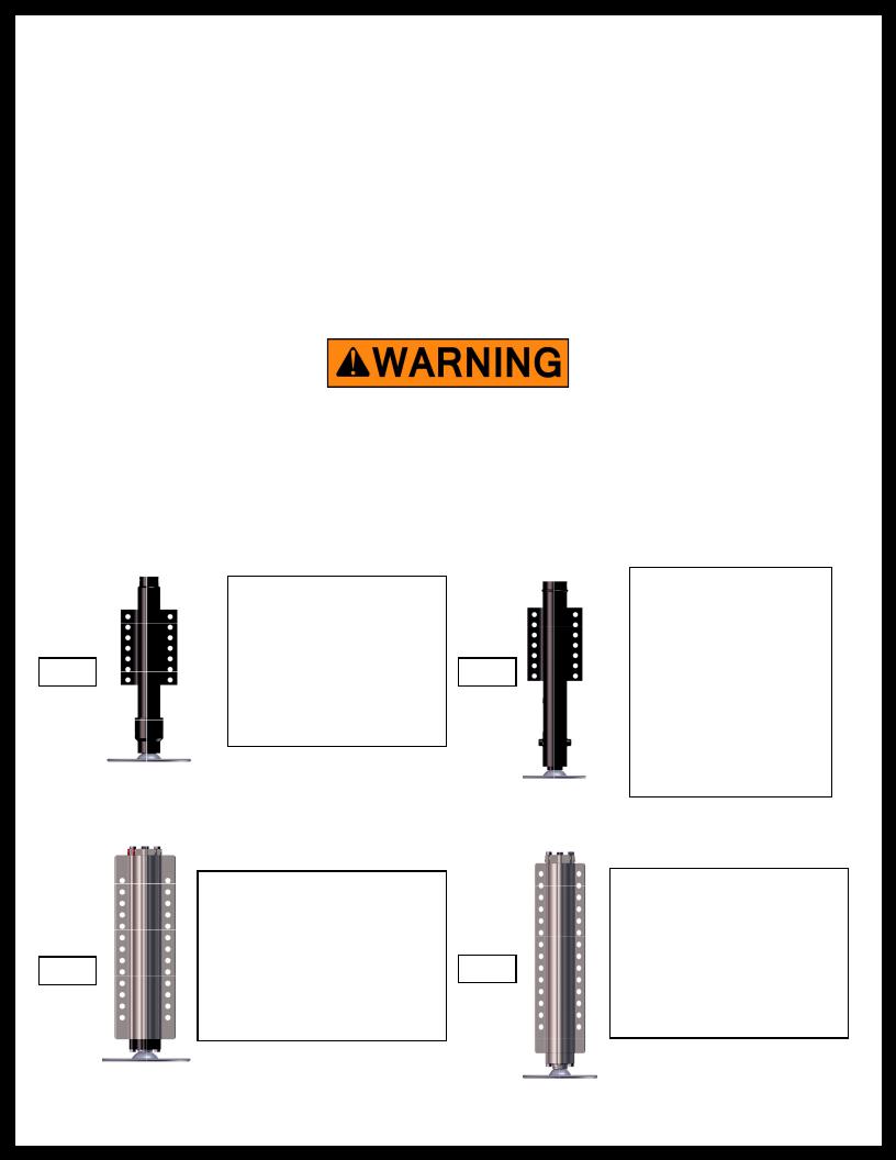
LCI Hydraulic Jacks
Steel Jacks - Bi-rotational Power Unit
|
|
Part # 113314 |
|
Part # 175176 |
|
|
|
CAPACITY - 12,000 lb. |
|
|
|
CAPACITY - 7,000 lb. |
|
|
|
|
|
STROKE - 15 in. |
|
|
|
STROKE - 13 3/4 in. |
|
|
|
|
|
H - 19 1/2 in. |
|
|
|
H - 18 1/4 in. |
|
|
|
|
|
D - 2 3/8 in. |
|
|
Fig. 1 |
D - 2 3/8 in. |
Fig. 2 |
|
|
9” SHOE-STANDARD |
|||
|
|
A - 2 1/2 in. |
|
|
|
|
|
||
|
|
|
12” SHOE-OPTION - 117238 |
|
|
|
9” SHOE-STANDARD |
|
|
|
|
|
|
|
|
|
12” SHOE-OPTION - 117238 |
|
FOUND ON FR GT UNITS |
|
|
|
|
|
|
|
|
|
359WHREG AND 391 |
|
|
|
|
ALL 4 JACKS ARE 12K. |
Aluminum Jacks - Unidirectional Power Unit |
|
|
||
|
|
Part #195860 |
|
Part # 236560 |
|
|
CAPACITY - 8,000 lb. |
|
CAPACITY - 14,000 lb. |
|
|
STROKE - 15 in. |
|
STROKE - 15.13 in. |
|
|
BORE - 2 in. |
|
BORE - 2 1/2 in. |
|
|
H - 21 3/16 in. |
|
H - 21 5/8 in. |
|
|
Fig. 4 |
||
|
Fig. 3 |
|||
|
ROD DIA. - 1.50 in. |
ROD DIA. - 1.875 in. |
||
|
|
|
||
|
|
9” SHOE-STANDARD |
|
9” FOOT PAD-STANDARD |
|
|
12” SHOE-OPTION - 117238 |
|
12” FOOT PAD-OPTION - 117238 |
Rev: 07.14.2014 |
Page 4 |
Untitled-1

Leveling System Controls
Leveling Features
•Automatic extension of jacks from full retract position (with automatic ground detection).
•Automatic leveling of jacks.
•Manual leveling of jacks.
•Automatic retraction of jacks (with automatic full retract detection).
•Air bag suspension features (configurable on/off).
•Emergency retract/user alarm mode (jacks not retracted and park brake disengaged).
•Automatic jack error detection and error mode.
•Configuration mode for Air features.
•Configuration mode for Leveling Zero Point.
System Wiring Requirements
•Battery power (2 ga. SAE J1127. Type SGX).
•Battery ground (2 ga. SAE J1127. Type SGX).
•Logic power (switched via ignition)
•Power brake signal (open=park brake disengaged, GND=park brake engaged).
•4-wire harness connecting Controller to Touch Panel.
•Jacks status input - Switched to GND
Note: Jacks not all up – switch closed to ground
Note: Jacks all up – switch open
Air and Auxiliary Features
System has the option to control external Air and Auxiliary features.
When enabled, the feature works according to the following logic:
•Air bag pressure automatically lowered when starting the auto or manual sequence to maximize lift of jacks.
•An Auxiliary mode activated when starting an auto retract sequence to fill air bags.
•Auxiliary is active when jacks are all retracted and park brake is disengaged to fill airbags.
Rev: 07.14.2014 |
Page 5 |
Untitled-1

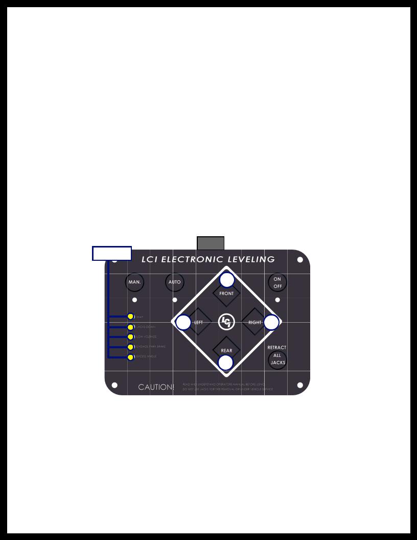
Touchpad Schematic
Fig. 5
Callout Description
AManual Operation - Places control panel in manual operation mode.
BManual Operation LED - Indicates control panel in manual operation mode.
CAutomatic Operation - Places control panel in automatic operation mode.
DAutomatic Operation LED - Indicates control panel in automatic operation mode.
EWait LED - Indicates to the operator to pause operation until the LED turns off.
FJacks Down LED - Indicates jacks are not fully retracted.
GLow Voltage LED - Indicates voltage has dropped below safe operable level. Solid LED indicates voltage is too low to operate system.
HEngage Park Brake LED - Flashes when park brake is disengaged; off when park brake has been engaged.
IExcess Angle LED - Coach may not be able to level in current location and must be moved to a more level location.
J |
Front Button - Controls operation of both front jacks. |
KLeft Button - Controls operation of both left jacks.
LRight Button - Controls operation of both right jacks.
M |
Rear Button - Controls operation of both rear jacks. |
NCoach Level LED - Indicates that the coach has been leveled.
OPower Button - Turns system on and off.
P |
Retract All Jacks - Retracts all jacks automatically. See page 12 for retract procedures. |
Rev: 07.14.2014 |
Page 6 |
Untitled-1
Level Zero Point Calibration
Before auto-leveling features are available, the Level Zero point must be set. This is the point to which the system will return when an auto leveling cycle is initiated.
To set the zero point (controller module must be fully secured in production-intent location), first use a carpenter's level to run a manual leveling sequence to get the vehicle to the desired level point; then activate the Level Zero point configuration mode.
This mode is enabled by performing the following sequence:
1.Turn panel off. Then turn panel on.
2.Perform the following:
•Press the Front (Fig. 5J) switch 5 times.
•Press the Rear (Fig. 5M) switch 5 times.
3.At this point all LED outputs will blink, and the buzzer will be off.
4.You are now in IDLE mode ready to set Zero Point.
5.With a carpenter’s level, confirm coach remains in level disposition. In IDLE MODE, the leveling system is in MANUAL MODE and can be used to make any corrections to level the coach.
6.When coach is completely leveled manually, press the Retract All (Fig. 5P) switch 3 times to set the zero point.
"Latched Out" Warning
LATCHED ERROR mode is “WAIT,” “JACKS DOWN,” “PARK BRAKE,” “EXCESS SLOPE” AND “LOW VOLTAGE” lights flashing (Fig. 6). This error is caused by either of these circumstances:
1.Battery voltage below 10.0V DC.
2.Retract time over 67 seconds in auto retract.
NOTE: This is the only LATCHED ERROR MODE.
NOTE: All revisions prior to “G” controllers treat this error as regular ERROR mode.
To RESET, push all 4 diamond-shaped jack buttons (Fig. 6A) at the same time.
Rev: 07.14.2014 |
Page 7 |
Untitled-1

Air and Auxiliary Feature Configuration
For Diesel Units with Airbag Suspensions ONLY:
•Feature is entered ONLY after zero mode programming.
•At this point the WAIT LED (Fig. 5E) will blink for 20 seconds. You are now in Air/Auxiliary Feature Configuration mode.
To enable Air Auxiliary features, perform the following:
•Press the RETRACT ALL (Fig. 5P) switch 3 times.
•User must do this within 20 seconds of entering this mode. To disable Air features, perform the following:
•Do nothing.
•After 20 seconds, module will exit mode with features disabled.
Error Mode
If any problem is detected with the jacks, the system will enter error mode. Error mode may be recognized by the blinking of LEFT, LEVEL and RIGHT LEDs.
The following errors are detected by this system:
•Jack over current/short circuit.
•Jack under current/ open circuit.
•Jack extending too long (ground not detected after 2 min).
•Jack retracting too long (fully retracted not detected after 2 min).
•Out of stroke detection during auto cycle (if enabled).
User Alarm Mode
If the alarm system detects that the park brake has been disengaged while at least one jack is not fully retracted and the sensor value changes in any axis more than a predefined amount, the panel will signal this error to the user.
When in alarm mode, all LEDs will flash and the buzzer will beep. The Status LEDs will show the system status. The system will perform an automatic retract.
No other features are available in this mode.
Miscellaneous
•The system will automatically shut down after 4 minutes of no operation.
•Auto leveling cycle cannot be started until all jacks are fully retracted. Make sure jacks are retracted before attempting to auto level (unit will perform full retract automatically if jacks are not down on the request of an auto cycle).
•System will refuse any operation when a low voltage condition is present.
•System will automatically alarm and retract if park brake is disengaged and jacks are not retracted with any change in sensor readings. In alarm mode, the only available feature is to retract all jacks.
•Please note the Wait LED shows the status of Air/ Auxiliary features.
•Please note that the LEDs blink differently when in special controller modes (error, alarm, and configuration). Learning how to recognize these modes is important. Excess slope LED blinks whenever the Y axis (vehicle length) is over 5o from programmed level point.
Rev: 07.14.2014 |
Page 8 |
Untitled-1

Prior to Operation
The leveling system should only be operated under the following conditions:
1.The coach is parked on a reasonably level surface.
2.The coach “PARKING BRAKE” is engaged.
3.The coach transmission should be in the neutral or park position.
4.The ignition is in the run position, or engine is running.
5.Be sure all persons, pets and property are clear of the coach while Lippert Leveling System is in operation.
Operation
Selecting A Site
When the coach is parked on an excessive slope, the leveling requirements may exceed the jack lift stroke capability. If the coach is parked on an excessive slope, the coach should be moved to a more level surface before the leveling system is deployed.
Automatic Leveling Procedure
NOTES:
•Refer to (Fig. 5) for questions regarding location and functions of the Lippert Components Inc. Electronic/Hydraulic Leveling System.
•Coach must be running for LCI Electronic/Hydraulic Leveling System to operate.
1.Push ON/OFF button on Control Panel. The system is now operational and the electronic level lights will become active.
2.Check to see that the Control Pad ENGAGE PARK BRAKE light is not flashing.
NOTE: Engage Parking Brake if ENGAGE PARK BRAKE light is flashing.
3.Push the AUTO button to begin the automatic leveling cycle.
Note: After starting the automatic leveling cycle it is very important that you do not move around in the coach until the unit is level and the green LCI logo light illuminates in the center of the touch pad. Failure to remain still during the leveling cycle could have an affect on the performance of the leveling system.
4.If further adjustments are necessary, simply push and hold the MAN button (Fig. 5A) for approximately 5 seconds until the light under this button is illuminated. Push the appropriate leg button to override the system and level the coach to your liking.
NEVER LIFT ALL THE WHEELS OFF THE GROUND TO LEVEL THE COACH!
Lifting all wheels off the ground may result in death or serious personal injury.
5.Push ON/OFF button to de-energize the system.
Rev: 07.14.2014 |
Page 9 |
Untitled-1

Manual Leveling Procedure
Note: When leveling your coach, the coach should be leveled from FRONT TO REAR first (steps 2-4). When the coach is level from FRONT TO REAR, then level the coach from LEFT TO RIGHT (step 5).
NOTE: Coach must be running for LCI Electronic/Hydraulic Leveling System to operate.
1.Push ON/OFF (Fig. 5O) button on control panel. The system is now operational and the ON/OFF (Fig. 5O) light will be lit. If ON/OFF (Fig. 5O) light is not lit, see PRIOR TO OPERATION, page 9.
2.Push and hold MAN button (Fig. 5A) for 5 seconds.
3.Push FRONT button (Fig. 5J) until jacks contact the ground.
4.Push REAR button (Fig. 5M) until jacks contact the ground.
5.Push button FRONT or REAR; if bubble is towards front of coach push REAR button; if bubble is towards rear of coach, push FRONT button. Keep button depressed until bubble is centered.
6.Push LEFT (Fig. 5K) or RIGHT (Fig. 5L) button; if bubble is towards left of coach, push RIGHT button; if bubble is towards right of coach push LEFT button. Keep button depressed until bubble is centered in vial.
Note: The right and left jacks are used to level the coach side to side. Pushing the LEFT (Fig. 5K) button on the control panel will extend both left jacks. Pushing the RIGHT button (Fig. 5L) on the control panel will extend both right jacks. Jacks always work in pairs, both front jacks together, both right side jacks, etc.
7.Repeat steps 2 through 5 if needed.
8.Turn power off to leveling system by pushing ON/OFF button (Fig. 5O).
9.Visually inspect all jacks to ensure all shoes are touching the ground. Should one of the rear jack shoes not be touching the ground, press the corresponding LEFT or RIGHT rear jack buttons to lower the corresponding jack to the ground.
NEVER LIFT ALL THE WHEELS OFF THE GROUND TO LEVEL THE COACH! Lifting all wheels off the ground may result in death or serious personal injury.
10. Push ON/OFF button (Fig. 5O) to de-energize the system.
Jack Retract Procedures
1.Energize the system by pushing ON/OFF button (Fig. 5O) on control panel. The ON/OFF light will be lit.
2.Push the RETRACT ALL JACKS button (Fig. 5P). All the jacks will start to retract and return to the full retract position. When all jacks return to full retract position the JACKS DOWN light (Fig. 5F) will go out.
Note: If you wish to stop the jacks from retracting, turn the system off and back on again by pushing the on/off pad twice. You can then re-level the coach by following steps 1-5 again.
3.When the JACKS DOWN light (Fig. 5F) goes out, push the ON/OFF button (Fig. 5O) on the Control Panel to de-energize the system. After a brief visual inspection around the coach to verify the jacks are fully retracted, you may proceed to travel.
Note: When in the MANUAL mode, if the RETRACT button is pushed the jacks will only retract as long as the RETRACT button is depressed. In AUTOMATIC mode, the RETRACT button need only be pressed once and released for the jacks to fully retract.
Rev: 07.14.2014 |
Page 10 |
Untitled-1
 Loading...