


G C 3.0
SERVICE4 P MANUAL6
Rev: 01.30.2015 |
Page 1 |
Ground Control 3.0 Service Manual

TABLE OF CONTENTS |
|
System and Safety Information |
2 |
Prior to Operation |
3 |
Touch Pad Diagram |
3 |
Operation |
4 |
Basic Jack Operation |
4 |
Unhitching from a Tow Vehicle |
4 |
Auto Level |
5 |
Auto Level Sequence |
5 |
Hitch Recognition |
5 |
Homing Jacks |
6 |
Zero Point Calibration |
6 |
Manual Override - Top of Jack Motor |
7 |
Manual Override - Bottom of Jack Motor |
8 |
Preventive Maintenance |
9 |
Troubleshooting - Touch Pad |
9 |
Special Jack Error Codes |
9 |
Touch Pad Error Codes |
9 |
Component Replacement |
11 |
Landing Gear Replacement |
11 |
Rear Jack Replacement |
12 |
Rear Sensor Replacement |
12 |
Controller Replacement |
17 |
Touch Pad Replacement |
18 |
Jack Motor Replacement |
18 |
4 - Point Wiring Diagram |
19 |
6 - Point Wiring Diagram |
20 |
Ground Control 3.0 OEM Assembly |
21 |
Ground Control 3.0 Components |
22 - 25 |
|
|
|
|
System and Safety Information
Failure to act in accordance with the following may result in death or serious personal injury. The use of the Ground Control 3.0 leveling system to support the unit for any reason other than which it is intended is prohibited by Lippert’s limited warranty. The Lippert leveling system is designed as a “leveling” system only and should not be used to provide service for any reason under the coach such as changing tires or servicing the leveling system. Any attempts to change tires or perform other service while unit is supported by the Ground Control 3.0 leveling system could result in damage to the 5th wheel and/or cause death or serious injury.
Be sure to park the unit on solid, level ground. Clear all jack landing locations of debris and obstructions. Locations should also be free of depressions. When parking the unit on extremely soft surfaces, utilize load distribution pads under each jack. People and pets should be clear of coach while operating leveling system. Never lift the unit completely off the ground. Lifting the unit so the wheels are not touching the ground will create an unstable and unsafe condition.
Rev: 01.30.2015 |
Page 2 |
Ground Control 3.0 Service Manual

Prior to Operation
The leveling system should only be operated under the following conditions:
1.The unit is parked on a reasonably level surface.
2.Be sure all persons, pets, and property are clear of the coach while the leveling system is in operation.
3.Make sure battery(ies) are fully charged and test at 12+VDC under load.
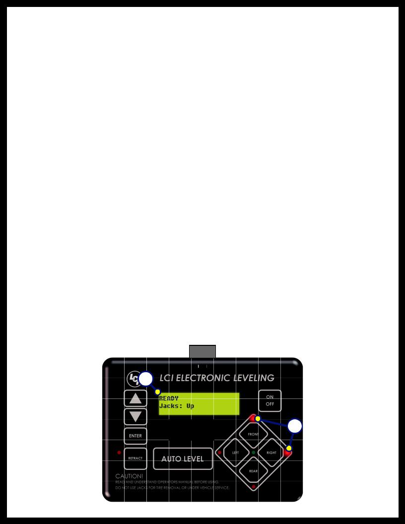
Touch Pad Diagram
Fig. 1
Callout Description
AUp Arrow - Scrolls up through the menu on LCD.
BDown Arrow - Scrolls down through the menu on LCD.
CEnter - Activates modes and procedures indicated on LCD.
DRetract - Places leveling system into retract mode. - Press and hold down for 1 second to initiate Auto Retract.
ELCD Display - Displays procedures and results.
FAuto Level - Places leveling system into auto level mode.
GFront Jack Button - Activates front jacks in manual mode.
HLeft Jack Button - Activates left jacks in manual mode.
I |
Right Jack Button - Activates right jacks in manual mode. |
J |
Rear Jack Button - Activates rear jacks in manual mode. |
K |
Power Button - Turns leveling system on and off. |
Rev: 01.30.2015 |
Page 3 |
Ground Control 3.0 Service Manual
Operation
Basic Jack Operation
Landing gear jacks can be operated any time the system is “ON”. By pushing the “FRONT” button (Fig. 1G), both front or landing gear jacks can be extended. By pushing either the "FRONT" and “LEFT” (Fig. 1H) or "FRONT" and “RIGHT” (Fig. 1I) buttons, the individual front jacks can be extended. If the touch pad is put in the retract mode, indicated by the orange illuminated LED next to the “RETRACT” button (Fig. 1D), the front jacks can be retracted together by pushing the “FRONT” button (Fig. 1G) or individually by pressing “LEFT” (Fig. 1H) or “RIGHT” (Fig. 1I) buttons, while simultaneously pressing the “FRONT” button (Fig. 1G).
NOTE: Middle jacks can only be operated in error mode. In order to engage middle jacks, press "LEFT" and "RIGHT" buttons simultaneously.
The rear jacks can only be extended when the touch pad is in the manual mode. Once system is in manual mode, pressing the “REAR” button (Fig. 1J) will extend both rear jacks at the same time. To extend individual rear jacks, press the “LEFT” (Fig. 1H) or “RIGHT” (Fig. 1I) buttons while simultaneously pressing the “REAR” button (Fig. 1J), depending on which jack needs to be operated. If the touch pad is put in the retract mode, indicated by the orange illuminated LED next to the “RETRACT” button (Fig. 1D), the rear jacks can be retracted together by pushing the “REAR” button (Fig. 1J) or individually by pressing either the “LEFT” (Fig. 1H) or “RIGHT” (Fig. 1I) buttons, while simultaneously pressing the “REAR” button (Fig. 1J).
NOTE: If the rear jacks will not operate individually using the method described above, but they operate properly when Auto Level is performed, the Twist Prevention Protection system has locked out the operation to prevent damage to the frame of the unit.
Unhitching from a Tow Vehicle
NOTE: Prior to unhitching from the tow vehicle, ensure unit is parked on a level surface and be sure to chock the tires of the unit.
1.Extend the inner legs of both landing gear 4-5 inches by pulling on the quick release pins.
2.Push “ON/OFF” (Fig. 1K). LCD Screen will light up and display “READY JACKS: UP” (Fig. 2A).
3.Push the “UP” arrow (Fig. 1A) to scroll to “Drop Front Jacks” option on LCD screen.
4.Red indicator lights (Fig. 2B) may come on, indicating the current disposition of the unit. In this case, the front and right sides of the unit are low.
5.Push “ENTER” (Fig. 1C). Both front landing gear jacks will go to ground and stop.
6.Push the “FRONT” button (Fig. 1G) extending the front landing gear to a sufficient height, which raises the front of the unit off of the tow vehicle’s 5th wheel hitch plate.
7.Pull tow vehicle away and park at a safe distance.
Fig. 2
Rev: 01.30.2015 |
Page 4 |
Ground Control 3.0 Service Manual
Auto Level
1.After unhitching from tow vehicle and parking the vehicle at a safe distance away from the unit, press the “ON/OFF” button (Fig. 1K) and then press “AUTO LEVEL” (Fig. 1F).
NOTE: Once the automatic leveling cycle has been started, it is important that there is no movement in the coach until the unit has completed the leveling process. Failure to remain still during the leveling cycle could have an effect on the performance of the leveling system.
NOTE: In order for hitch recognition feature to function, the auto level sequence MUST be started with the front of the unit above level.
Auto Level Sequence
1.When Auto Level Sequence begins, the front of the unit will lower slightly to a point below level. The coach will then stop and raise up to the point where it is level from front to rear.
2.Rear leveling jacks are grounded.
3.A side to side leveling sequence occurs.
NOTE: At this point on the 6-point system, the two middle jacks are grounded to stabilize the unit. These two jacks do not level the unit.
4.Each jack will perform a final grounding touch.
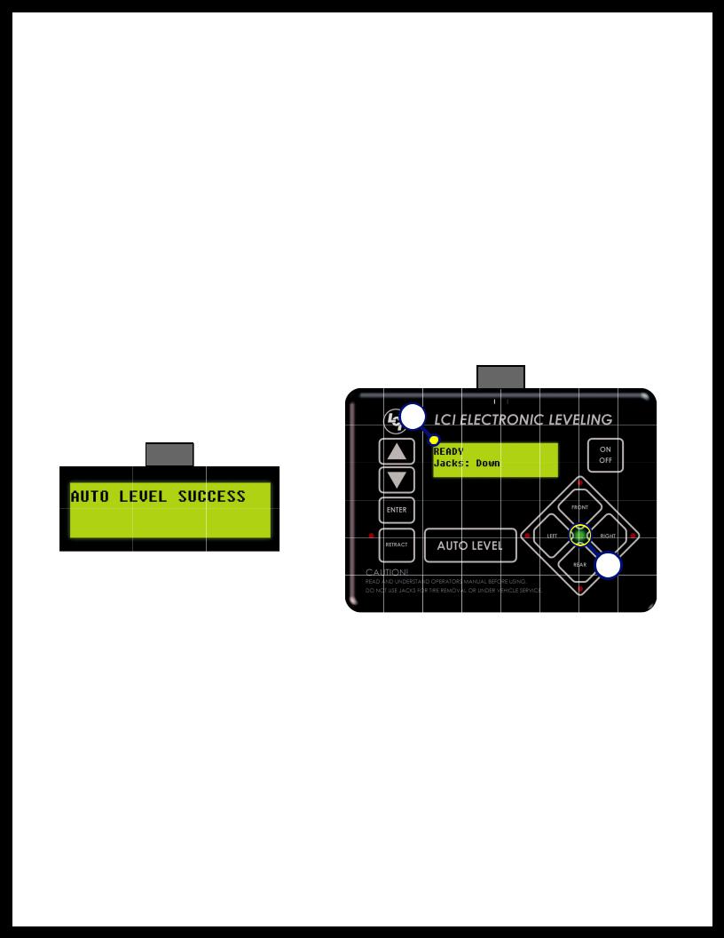
5.LCD will read “AUTO LEVEL SUCCESS” (Fig. 3).
6.LCD will then read “READY Jacks: Down” (Fig. 4A), and the green LED at the center of the four jack buttons will be illuminated (Fig. 4B).
Fig. 4
Fig. 3
NOTE: If the AUTO LEVEL sequence does not perform as described, place the system in the manual mode and test that the jacks operate correctly by pushing their coordinating buttons on the touch pad; i.e. FRONT button operates only the front jacks.
Hitch Recognition
1.Turn on touch pad.
2.Press the left and right buttons simultaneously (Fig. 1H/I).
3.All leveling jacks will retract first, then the landing gear will extend to raise the unit to the height where the auto level sequence was started.
NOTE: If the auto level sequence was started with the front of the unit in a below-level condition, the Hitch Recognition will not function and the LCD will display “Feature Disabled.” In order for hitch
recognition feature to function, the auto level sequence MUST be started with the front of the unit above level.
Rev: 01.30.2015 |
Page 5 |
Ground Control 3.0 Service Manual
Homing Jacks
1.Introduce an error - disconnect one of the hall effect sensor wires at the controller.
2.Attempt to operate the jack that is associated with the sensor wire that was disconnected. The touch pad screen will display an error for that jack.
3.Reconnect the hall effect sensor wire. Manually extend all jacks down a minimum of 6 inches.
4.Press and hold the retract button until all of the jacks begin to retract. The jacks will retract until they reach the hard current limit.
5.The jacks are now “homed.”
NOTE: If the jacks do not retract, an error should display on the touch pad screen. This is typically caused by wiring interruption.
NOTE: In order to "home" jacks, middle jacks MUST also be extended. Refer to Basic Jack Operation for middle jack operation.
Zero Point Calibration
The “Zero Point” is the programmed point that the unit will return to each time the Auto Level feature is used. The “Zero Point” MUST be programmed prior to using the Auto Level feature to ensure the proper operation of the system.
NOTE: Prior to starting this procedure, double check all connections on the controller, jacks, and touch pad.
1.Manually run the jacks to level the unit. This is best achieved by placing a level in the center of the unit and leveling it both front to back and then side to side. (See “Basic Jack Operation” for instructions on how to manually operate the system).
2.Once the unit is level, turn off the touch pad.
3.With the touch pad off, press and release the “FRONT” button (Fig. 1G) five (5) times and then press and release the “REAR” button (Fig. 1J) five (5) times.
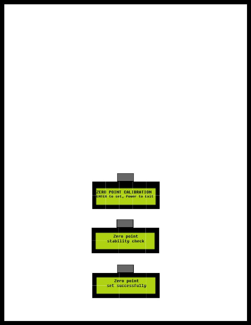
4.The touch pad will flash and beep and the display will read “ZERO POINT CALIBRATION ENTER to set, Power to Exit” (Fig. 5).
5.To set the current position as the zero point, press the “ENTER” button (Fig. 1C).
Fig. 5
6.LCD display will read “Zero Point stability check” (Fig. 6).
Fig. 6
7.LCD display will read “Zero point set successfully” once process is complete (Fig. 7).
Fig. 7
8.The system will set this point as its level state and the touch pad will turn off.
Rev: 01.30.2015 |
Page 6 |
Ground Control 3.0 Service Manual
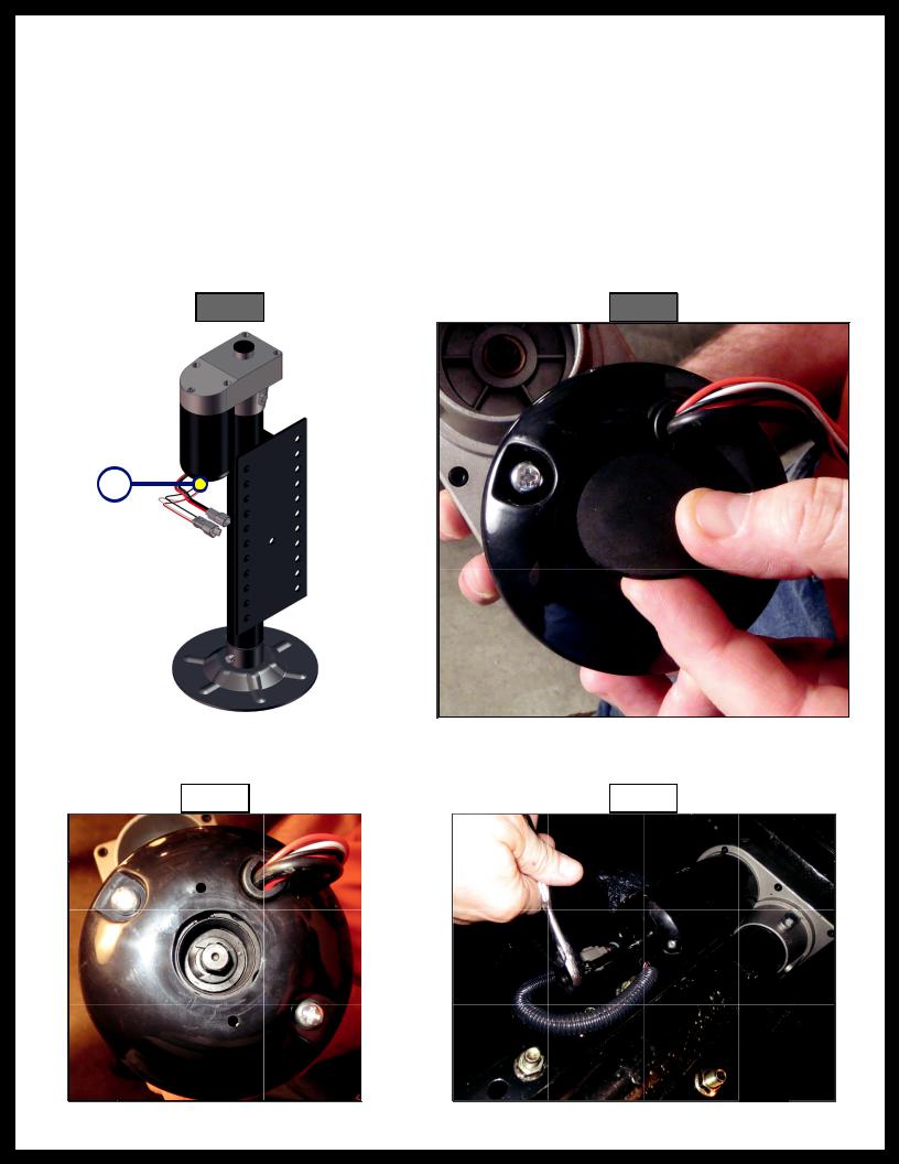
Manual Override - Top of Jack Motor
NOTE: Use of a 12V-18V cordless screw gun or pneumatic screw gun is acceptable to manually override the jacks. Do not use an impact screw gun to perform the override procedure, as this may damage the motor.
If manual override is necessary on any jack in the system, there are two options. The following process will describe how to use the top override. See next page for the bottom override.
Tools needed: 3⁄8” drive ratchet and extension (no socket).
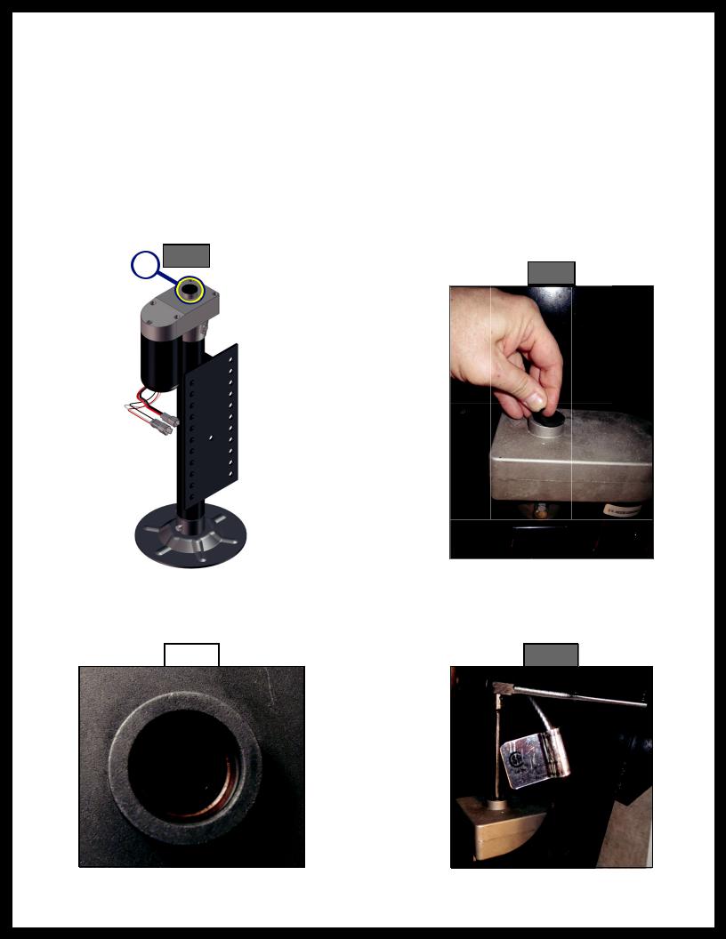
1.Find the port on the top of the jack motor (Fig. 8A).
2.Remove the rubber plug (Fig. 9).
Fig. 8
3.Insert the 3⁄8” drive into the port (Fig. 10).
4.Turn override until the jack extends or retracts to desired position (Fig. 11).
Rev: 01.30.2015 |
|
Page 7 |
|
Ground Control 3.0 Service Manual
Manual Override - Bottom of Jack Motor
NOTE: Use of a 12V-18V cordless screw gun or pneumatic screw gun is acceptable to manually override the jacks. Do not use an impact screw gun to perform the override procedure, as this may damage the motor.
If manual override is necessary on any jack in the system, there are two options. The following process will describe how to use the bottom override. See previous page for the top override.
Tools needed: 3⁄8” drive ratchet and extension, 5⁄16” socket.
1.Find the port on the bottom of the jack motor (Fig. 12A).
2.Remove the rubber plug (Fig. 13).
Fig. 12
3.Insert the 5⁄16” socket into the port (Fig. 14).
4.Turn override until the jack extends or retracts to desired position (Fig. 15).
Rev: 01.30.2015 |
|
Page 8 |
|
|
|
Ground Control 3.0 Service Manual
 Loading...