

Page 1
Shock Kit
Aftermarket Manual
Shock Kit
Aftermarket
Manual
Table of Contents
Introduction ............................................ 2
Parts List ............................................... 2
Preparation............................................. 2
Installation ............................................2-3
Notes................................................... 4
www.lippertcomponents.com (574) 537-8900 Rev: 01.15 - Shock Kit Aftermarket Manual
1
Page 2
Shock Kit
Aftermarket Manual
Introduction
Instantly improve your ride with our complete shock mount kits.
Shocks help to efciently manage axle spring movement to
provide a smoother, more comfortable ride.
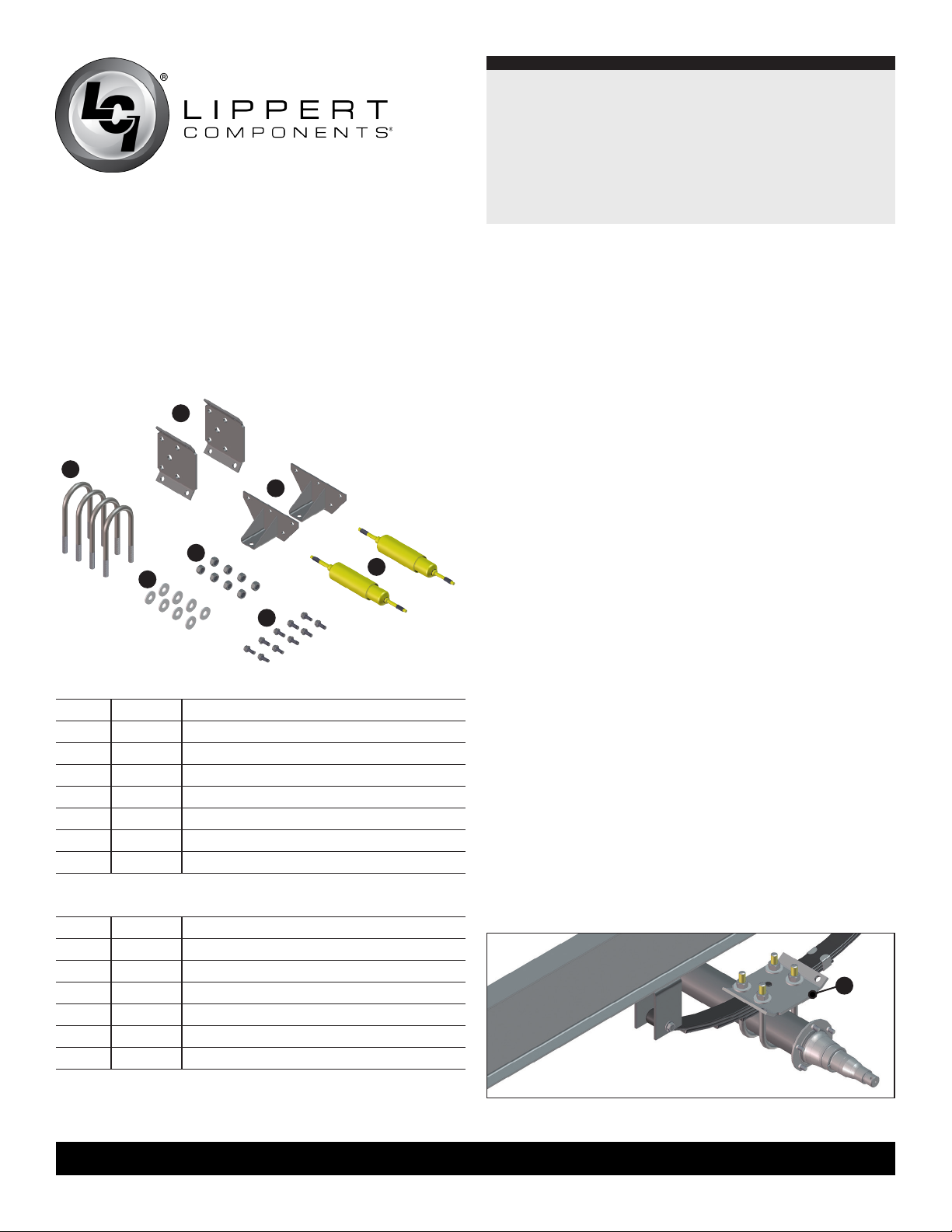
Parts List
B
A
E
D
G
C
F
281281 - 3” Axle Beam Kit
Letter Part# Description
A 2139541 U-bolt
B 2139531 Shock Mounting Tie Plate
C 170997 9/16” Washer
D 182274 9/16” Nut
E 275046 Shock Upper Mounting Bracket
F 191021 3/8” - 16 x 1” Self Tapping Bolt
G 177734 Shock
Preparation
Tools Required:
• Floor Jack
• Drill / Socket Wrench
• Torque Wrench
• 3/8” Socket
• 9/16” Socket
• 11/32” Drill Bit
• Tape Measure
• M a r ke r
1. Check to make sure slide-out cross shafts are not in the way.
2. Measure clearance between inside of tire and I-beam ange.
Minimum clearance is 2 1/2”
Installation
This process will need to be repeated on each end of the axle.
NOTE: Tires removed from images for clarity.
1. Raise trailer and jack up the axle to release pressure on the
springs.
2. Remove old u-bolts and tie plate.
3. Install new tie plate with the longer side facing outward
(Fig. 1A) and torque the u-bolts to 90 ft lbs.
281255 - 2 3/8” Axle Beam Kit
NOTE: Do NOT use old components.
Letter Part# Description
A 122073 U-bolt
B 1938281 Shock Mounting Tie Plate
D 122079 1/2” x 20 Nut
E 275047 Shock Upper Mounting Bracket
F 191021 3/8” - 16 x 1” Self Tapping Bolt
G 177734 Shock
Fig. 1
www.lippertcomponents.com (574) 537-8900 Rev: 01.15 - Shock Kit Aftermarket Manual
2
A
Page 3

Shock Kit
Aftermarket Manual
4. Compress the shock (Fig.2) and make a mark on the inner
shock where the outer shock stops (Fig. 2A and 3A).
5. Release compression (Fig. 3). Measure the stroke (Fig. 3B)
and make a mark on the inner shock that is one half of the
stroke length (Fig. 3C).
6. Measure the shock length (Fig. 4A) when the shock is
compressed to the halfway mark made in Step 5.
B
C
A
Fig. 2 Fig. 3 Fig. 4
A
A
7. Lower the trailer back down onto tires and level so the
equalizer(s), if equipped, are parallel to the frame and there is
a full load on the springs.
9. Align the bottom of the extended portion of the upper shock
mounting bracket to the mark made on the I-beam in Step 8
and drill 11/32” pilot holes.
10. Use the 3/8” self-tapping bolts to secure the upper shock
mounting bracket to the I-beam (Fig. 6).
11. Remove nut, washer and rubber grommet from both sides of
the shock.
12. Place the shock into the shock mounting lip on the tie plate
and compress it to t into the upper mounting bracket.
13. Apply the rubber grommet (Fig. 7A), washer (Fig. 7B)
and nut (Fig. 7C) (in that order) and tighten to secure the
shock (Fig. 8).
NOTE: Do NOT over-tighten. Tighten until the rubber grommet
(Fig. 7A) increases diameter equal to the washer (Fig. 7B).
8. Make a measurement perpendicular to the shock mounting lip
on the tie plate that is the same distance measured in Step 6
(Fig.4A) + 2” and make a mark on the I-beam parallel to the
shock mounting lip on the tie plate (Fig. 5A).
NOTE: Mount shocks pointing outwards (away from the shackle
kit, equalizer and/or center point) to get the best performance
from the shocks.
NOTE: Dry t the shock to be sure it does not exceed a 45 degree
Fig. 6
angle or it will not function.
A
Fig. 4A + 2”
Fig. 5
www.lippertcomponents.com (574) 537-8900 Rev: 01.15 - Shock Kit Aftermarket Manual
Fig. 8
3
Fig. 7
A
B
C
Page 4

Notes
Shock Kit
Aftermarket Manual
Manual information may be distributed as a complete
document only, unless Lippert Components provides explicit
consent to distribute individual parts.
All manual information is subject to change without notice.
Revised editions will be available for free download at www.
lippertcomponents.com. Manual information is considered
factual until made obsolete by a revised version.
Please recycle all obsolete materials and contact Lippert
Components with concerns or questions.
www.lippertcomponents.com (574) 537-8900 Rev: 01.15 - Shock Kit Aftermarket Manual
4
 Loading...