

Page 1

Page 2

2
Table of Contents
Introduction, Required Components, and Important Notes 3
Mounting the Motor Bearing Block 4
Mounting the Controller Module 4
Inserting the Gear Racks 5
Installing the Stop Blocks 5
Programming 6
Rev: 08.15.2013
Page 3
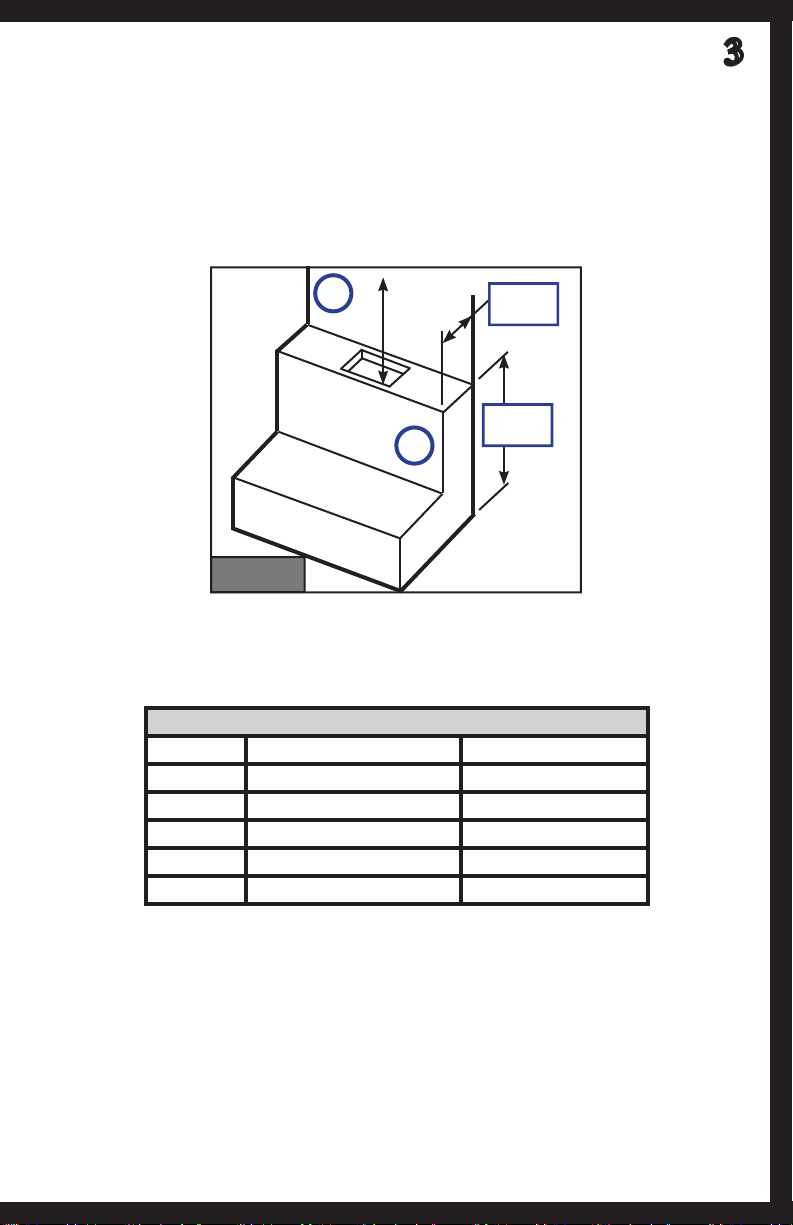
This manual is a guide for the installation of the Schwintek Bunk Lift System. Exact
installation procedure depends on RV manufacturer's design of bunk bed attachment
brackets and surrounding structures. At RV manufacturer's discretion, the motor
mounting blocks can be attached to either the seat back structure (Fig. 1A) or the wall
structure (Fig. 1B). Mounting to the seat back structure will not conceal the gear teeth,
however mounting to the wall structure will conceal the gear teeth. Either mounting
surface must contain sufficient backing material to support the assembly.
3
A
Approx.
4"
Approx.
37"
Fig. 1
NOTE: Seat cushions not shown.
Components Required for Installation
# Req. Description LCI Part Number
2 Gear Rack Assembly Varies by length
2 Motor 236575
2 Motor Bearing Block 327495
2 Wire Harness Varies by length
1 Controller 333397
NOTE: Periodic light lubrication (CRC PowerLube or equivalent) of the gear racks may
be necessary if gear chatter sounds occur due to normal wear.
NOTE: Consumer labels for the following are the responsibility of the RV manufacturer:
Bed is not to be occupied, loaded or used for cargo storage in any way while being
raised or lowered. The dinette/bed setting is not to be occupied during raising or
lowering the bunk bed.
NOTE: Development of a travel latch when bed is in raised position is responsibility of
RV manufacturer.
Rev: 08.15.2013
Page 4

4
1. Mount motor bearing blocks to load-bearing structure using (4) 1/4 -20 bolts
per block. The mounting bolt pattern is shown in Fig. 2. Use the measurements
provided to create a template for the bolt holes.
TOP
2.175”
4.500”
0.266” Ø x4
Motor
Bearing
Block
Fig. 2
NOTE: Motor bearing blocks must be mounted in such a way to ensure the gear racks
raise and lower perpendicular to the coach floor and parallel to walls. Do not use
oversized holes as it will cause the assembly to tear away from the mounting structure.
2. Mount controller module in an area accessible to service but protected from
damage. Standard harness length is 15 feet. Longer harness lengths are available
if required for manufacturer specific applications.
2.918”
BOTTOM
Rev: 08.15.2013
Page 5

3. Insert gear racks into motor bearing blocks by aligning V-grooves in the rack
to the V-rollers in the motor bearing blocks. Insert until the gear in the motor
bearing blocks comes into contact with the serpentine groove in the gear rack as
shown below (Fig. 3).
Fig. 3
4. Connect motors to controller and controller to 12v power source.
NOTE: Type and location of Raise/Lower switch to prevent unsupervised and
unintended operation is responsibility of RV manufacturer.
5. Operate motors to lower gear racks into motor bearing blocks to engage lower
V-rollers.
5
6. Lower gear racks sufficiently to install stop blocks as shown using socket head
screws and lock washers provided (Fig. 4).
Fig. 4
Rev: 08.15.2013
Page 6

6
7. Attach bunk bed mounting brackets and bunk bed to gear racks.
NOTE: Bunk bed and method of attachment to the Bunk Lift System is responsibility of
the RV manufacturer. Bunk bed must be centered on the Bunk Lift System’s gear rack
lifting posts. Connect motors to controller and controller to 12v power source.
NOTE: Location of Raise/Lower switch to prevent unsupervised operation is
responsibility of RV manufacturer.
PROGRAMMING
1. Homing the Bunk Lift for the first time:
2. Using the wall switch, extend the room all of the way out until it stops. Conduct
A. Using the wall switch, press the “IN” button.
B. Quickly verify that both motors are moving in the same direction, if not stop
immediately and remedy problem.
C. Allow the Bunk Lift to power all of the way in and continue pressing the “IN”
button until both sides have completely stopped and the motors turn off by
themselves.
D. Let off the “IN” wall switch and check the red and green LED lights on
the circuit board and confirm that both are on (they will both turn off
automatically after one minute).
E. If only one of the LEDs is on, go back to the wall switch, press the “OUT”
button for one second and release and repeat step (a) until both LEDs are
on.
the following inspections:
A. Verify the room did full stroke and that the interior seals are evenly
compressed.
B. Verify the vertical wipe seals are in uniform contact with the side walls of
the slide box.
C. Verify the upper and lower wipe seals are in uniform contact with the floor
and ceiling.
D. Verify that all of the floor rollers are in constant contact with the slide box
floor.
E. Verify the lower wipe seal is of proper length and is clear of all of the rollers.
F. Verify the exterior top wipe seal is overlapped and glued at each corner to
the vertical wipe seal.
3. (Optional) Connect an amp meter to the incoming power to the control board
and extend and retract the room. The slide should operate at a consistent amp
load through out it’s entire stroke. Unusually high amps, or amp spikes during
the stroke are a sure sign of a troubled installation.
SETTING STOP POINTS
1. Lower the Bunk Lift into the desired position and press the white calibration
button on the receiver once.
2. Raise the Bunk Lift into the desired position and press the white calibration
button on the receiver once.
3. Test receiver's programming by lowering and raising the Bunk Lift.
Rev: 08.15.2013
Page 7

NOTES
7
Rev: 08.15.2013
Page 8

All information contained within may be distributed as a full document only, unless otherwise
permitted by explicit consent of Lippert Components Inc. to distribute individual parts.
All information contained within is subject to change without notice. New editions will be
posted on www.lci1.com and can be downloaded for free. Information contained within is
considered factual until made obsolete by a *NEW* revision.
Please recycle all obsolete materials.
For all concerns or questions, please contact
Lippert Components, Inc.
Ph: (574) 537-8900 Web: www.lci1.com Email: warranty@lci1.com
 Loading...