

Page 1

LCI Level-Up® Motorhome
Leveling (2013-Present)
OWNER'S MANUAL
Rev: 07.02.2018 Level-Up® Motorized Leveling LCD Owner's Manual
Page 2

TABLE OF CONTENTS
System Information 3
Prior To Operation 3
System Description 3
Component Description 4
Maintenance 4
Fluid Recommendation 4
Preventative Maintenance Procedures 4
Aluminum Jacks 5
Power Unit Components 6
Touch Pad Controls 7
Level Zero Point Calibration 8
For Diesel Units With Air Bag Suspensions ONLY: 8
Miscellaneous 8
Low Voltage Signal 9
Error Mode 9
Excess Angle 9
Error Mode 9
Operation 10
Selecting A Site 10
Automatic Leveling Procedure 10
Automatic Leveling Descriptive Logic 10
Manual Leveling Procedure 11
Jack Retract Procedures 11
Manual Override - Jacks 12
Manual Override - Power System 12
Automatic Safety Shuto 13
Drive Away Protection System 13
“Jacks Down" Alarm 13
Fluid Recommendation 13
Wiring Diagram 15
Plumbing Diagram 16
Bill of Materials 17
Level-Up® Motorized Leveling 18
Level-Up® Motorized Leveling 19
Level-Up® Motorized Leveling 20
Level-Up® Motorized Leveling 21
Level-Up® Motorized Leveling 22
Level-Up® Motorized Leveling 23
Level-Up® Motorized Leveling 24
Notes 25
Rev: 06.29.18
Page 2
CCD-0001535
Page 3

System Information
Failure to act in accordance with the following may result in serious personal injury or death.
The use of the LCI Level-Up® Motorhome Leveling System to support the coach for any reason other than
which it is intended is prohibited by Lippert's Limited Warranty. The LCI Level-Up® Motorhome Leveling
System is designed as a "Leveling" system only and should not be used to provide service for any reason
under the coach, such as changing tires or servicing the leveling system.
Lippert Components Inc. recommends that a trained professional be employed to change the tires on the
coach. Any attempts to change tires or perform other services while coach is supported by the LCI Level-
Up® Motorhome Leveling System could result in death, serious injury and/or damage to the motor home.
Prior To Operation
The leveling system shall only be operated under the following conditions:
1. The coach is parked on a reasonably level surface.
2. The coach “PARKING BRAKE” is engaged.
3. The coach transmission should be in the neutral or park position.
4. Be sure all persons, pets and property are clear of the coach while LCI Level-Up® Motorhome Leveling
System is in operation.
5. Clear all jack landing locations of debris and obstructions. Locations should also be free of depressions.
6. When parking the coach on extremely soft surfaces, utilize load distribution pads under each jack.
7. Be sure to keep hands and other body parts clear of fluid leaks. Oil leaks in the LCI Level-Up®
Motorhome Leveling System may be under high pressure and can cause serious skin penetrating
injuries.
8. Never lift the coach completely off the ground. Lifting the coach so the wheels are not touching the
ground will create an unstable and unsafe condition.
NOTE: After starting the automatic leveling cycle it is very important that you do not move around in the
coach until the unit is level and the green LCI logo light illuminates in the center of the touch pad.
Failure to remain still during the leveling cycle could have an effect on the performance of the
leveling system.
System Description
The LCI Level-Up Motorhome Leveling System is an electric/hydraulic system. A 12V DC electric motor
drives a hydraulic pump that moves fluid through a system of hoses, fittings and jacks to level and stabilize
the coach.
Mechanical portions of the LCI Level-Up Motorhome Leveling System are replaceable. Contact Lippert
Components, Inc. to obtain replacement parts.
Rev: 06.29.18
Page 3
CCD-0001535
Page 4

Component Description
The LCI Level-Up Motorhome Leveling System consists of the following major components:
Lippert jacks are rated at a lifting capacity appropriate for your coach. Each jack has a 9” diameter
(63.5-square-inch) shoe on a ball swivel for maximum surface contact on all surfaces. (12” dia. - 113-squareinch shoe also available.)
Each jack is powered from a central 12V DC motor/pump assembly, which also includes the hydraulic oil
reservoir tank, control valve manifold, and solenoid valves.
The LCI Level-Up Motorhome Leveling System is controlled electronically from the driver’s seat of the
coach. The control panel is mounted in the dash. The system can be operated in a manual mode or a fully
automatic mode.
Maintenance
Fluid Recommendation
The LCI Level-Up Motorhome Leveling System is pre-filled, primed and ready to operate direct from the
manufacturer. Automatic transmission fluid (ATF) with Dexron III or Mercon 5 or a blend of both is recommended
by Lippert Components, Inc. Specific fluid information can be found on Page 15.
NOTE: In colder temperatures (less than 10° F) the jacks may extend and retract slowly due to the fluid’s
molecular nature. For cold weather operation, fluid specially formulated for low temperatures may
be desirable. Please consult fluid specifications on Page 14.
Preventative Maintenance Procedures
1. Check fluid in reservoir every 12 months. If fluid is a clear, red color, do not change. If fluid is milky, pink
and murky, and not clear red in color, drain reservoir and add new fluid. Use recommended fluid (see
Page 14).
A. Check fluid only when all jacks are fully retracted.
B. When checking fluid level, fill to within ¼ to ½ inch of fill spout.
2. Inspect and clean all Power Unit electrical connections every 12 months. If corrosion is evident, spray
unit with WD-40 or equivalent.
3. Remove dirt and road debris from jacks as needed.
Your coach should be supported at both front and rear axles with jack stands before working underneath.
Failure to do so may result in personal injury or death.
4. If jacks are down for extended periods, it is recommended to spray exposed leveling jack rods with a
silicone lubricant every seven days for protection. If your coach is located in a salty environment, it is
recommended to spray the rods every 2 to 3 days.
NOTE: OEM to install attachment brackets for leveling jacks.
Rev: 06.29.18
Page 4
CCD-0001535
Page 5

Aluminum Jacks
Fig. 1
Fig. 2 Fig. 3
Fig. 1 - 433458
CAPACITY - 8,000 lb.
STROKE - 15.00 in.
BORE - 2.00 in.
H - 21.375 in.
ROD DIA. - 1.50 in.
9” FOOTPAD-STANDARD
12” FOOTPAD-OPTION - 117238
Fig. 2 - 236560
CAPACITY - 14,000 lb.
STROKE - 15.13 in.
BORE - 2.50 in.
H - 21.50 in.
ROD DIA. - 1.875 in.
9” FOOTPAD-STANDARD
12” FOOTPAD-OPTION - 117238
Fig. 3 - 258550
CAPACITY - 20,000 lb.
STROKE - 16.00 in.
BORE - 3.00 in.
H - 23.063 in.
ROD DIA. - 2.25 in.
9” FOOTPAD-STANDARD
12” FOOTPAD-OPTION - 117238
Rev: 06.29.18
Page 5
CCD-0001535
Page 6

Power Unit Components
Motor Solenoid
12V DC
Power
Fig. 4
12V DC Motor
Ground
Power
Pressure
Fill Cup
Switch
Disconnect for
Fig. 5
Flush and Fill
Extend
Fittings
Quick
Disconnect for
Flush and Fill
Quick
Hydraulic
Manifold
Valve and
Valve Coil
Return
Fittings
1. Fittings - High Pressure O-Ring Face - Size 4
2. Hose - ¼" I.D. 3000PSI - W.P. Rated
NOTE: Fittings are labeled with port assignments found stamped into the manifold for easy identification.
Rev: 06.29.18
Page 6
CCD-0001535
Page 7

Touch Pad Controls
Fig. 6
A
E
K
B
C
F
H
G
D
I
J
Callout Description
A Up Arrow - Scrolls up through the menu on LCD.
B Down Arrow - Scrolls down through the menu on LCD.
C Enter - Activates modes and procedures indicated on LCD.
D Retract - Places leveling system into retract mode. - Manual mode ONLY
E LCD Display - Displays procedures and results.
F Auto Level - Places leveling system into auto level mode.
G Front Jack Button - Activates both front jacks in manual mode.
H Left Jack Button - Activates both left jacks in manual mode.
I Right Jack Button - Activates both right jacks in manual mode.
J Rear Jack Button - Activates both rear jacks in manual mode.
K Power Button - Turns leveling system on and off.
Rev: 06.29.18
Page 7
CCD-0001535
Page 8

Level Zero Point Calibration
Before auto leveling features are available, the Level Zero point MUST be set. This is the point to which the
system will return when an auto leveling cycle is initiated.
To set the zero point (controller module MUST be fully secured in production-intent location), first run a
manual leveling sequence to get the vehicle to the desired level point. Then activate the Level Zero point
configuration mode.
This mode is enabled by performing the following sequence:
1. Turn panel off.
2. Press the Front switch 10 times (On Winnebago units, press FRONT 5 times).
3. Press the Rear switch 10 times (On Winnebago units, press REAR 5 times).
4. At this point, a tone will sound and the display will read ZERO POINT CALIBRATION.
5. Press ENTER to set the zero point.
6. Screen will then display Zero Point Stability Check and PLEASE WAIT.
7. Tone will sound and the screen will display ZERO POINT SUCCESSFUL.
8. Control will then turn off.
For Diesel Units With Air Bag Suspensions ONLY:
The leveling control will automatically detect an air bag system. If the unit does not use air bags, the display
will read “NO” for air bag control. If the display reads "NO," but an air bag system is present on the unit:
1. Confirm harness is connected properly.
2. Run Auto-Level function.
3. Recalibrate the Zero Point.
4. If the air bag system is still not being detected, contact the OEM for more information.
User Alarm Mode
If the alarm system detects that the park brake has been disengaged while at least one jack is not fully
retracted and the sensor value changes in any axis more than a predefined amount, the panel will signal this
error to the user.
When in alarm mode, all LEDs will flash and the buzzer will beep. The Status LEDs will show the system
status.
The system performs an automatic retract.
No other features are available in this mode.
Miscellaneous
• The system will automatically shut down after 4 minutes of no operation.
• Auto leveling cycle cannot be started until all jacks are fully retracted. Make sure jacks are retracted
before attempting to auto level. (Unit will perform full retract automatically if jacks are down on the
request of an auto cycle.)
• System will refuse any operation when a low voltage condition is present.
• System will automatically alarm and retract if park brake is disengaged and jacks are not retracted
with any change in sensor readings. In alarm mode, the only available feature is to retract all jacks.
• Please note WAIT display shows the status of Air/Auxiliary features.
NOTE: The LEDs blink differently when in special controller modes (error, alarm, and configuration).
Learning how to recognize these modes is important. Excess angle LED blinks whenever the Y axis
(vehicle length) is over 5o from programmed level point.
Rev: 06.29.18
Page 8
CCD-0001535
Page 9

Low Voltage Signal
1. The vehicle requires 12.7V DC to operate in the AUTO mode. If the voltage is too low, the screen will
display LOW VOLTAGE. If voltage drops below 12.7V DC, the system will only operate in the MANUAL
MODE and continue to display LOW VOLTAGE.
2. Minimum Voltage - If voltage drops below 9.5V DC during AUTO or MANUAL operation LOW VOLTAGE
will appear in the screen and the system will cease operating.
Error Mode
Excess Angle
1. The control will not operate at extreme slopes, i.e. 3.5 degrees fore and aft and 3.5 degrees side to
side.
2. If the coach indicates “EXCESS ANGLE” or “JACKS STROKED OUT“ during an auto level cycle, move the
coach to a more level spot.
Error Mode
NOTES:
• If an error occurs before or during operation, the error will be displayed in the LCD and an alarm will
sound. To reset all error or service displays, push RETRACT and ENTER at the same time.
• All normal functions will be disabled when the system is in Error Mode.
• Auto Level can only commence if running voltage is 12.7V DC or above.
• Auto Level operation will halt if running voltage drops to 9.5V DC.
• Manual Level operation can be performed at all running voltages above 9.5V DC.
Error Text Description
Excess Angle Excess slope for auto leveling
Feature Disabled Control not zeroed
External Sensor Remote sensor short or disconnected
Out of Stroke
Check campsite for even, level ground and turn engine
on - Check battery voltage under load.
Low Voltage Turn engine on - Check battery voltage under load.
Function Aborted Panic stop
Jack Timeout Auto mode/Retract timeout
Auto Level Fail Unable to level
Not Configured Control not zeroed
Zero Not Set Control not zeroed
Battery Voltage Turn engine on - Check battery voltage under load
Apply Park Brake to Auto Level Set parking brake
Unit has retracted for longer
than 50 seconds
Retract timeout, return leveling jacks for service.
Latched retract mode
Unable to Finish Leveling Move coach to a more level site
Check Wiring
Touch Pad is powered, but not communicating with
the controller. Check pin 1 and 2 of touch pad harness.
Caution, Excess Run Time Pump run too long in manual mode
Latched Retract / Service
Rev: 06.29.18
Check for leaking jack hose or fitting, reset by pressing
retract and enter at the same time.
Page 9
CCD-0001535
Page 10

Operation
Selecting A Site
When the coach is parked on an excessive slope the leveling requirements may exceed the jack lift stroke
capability. If the coach is parked on an excessive slope, the coach should be moved to a more level surface
before the leveling system is deployed.
EXCESS ANGLE will appear on the LCD screen if the coach is 3.5 degrees out of level front to rear or side to
side. See Page 9.
Automatic Leveling Procedure
NOTE: Coach MUST be running for LCI Electronic Leveling System to operate.
1. Push ON/OFF button on Control Panel. The system is now operational and the electronic level lights
will become active.
2. Check to see that the Control Pad ENGAGE PARK BRAKE is engaged.
3. Push the AUTO LEVEL button to begin the automatic leveling cycle.
4. Push ON/OFF button to de-energize the system.
Automatic Leveling Descriptive Logic
Grounding: Steps 1-3 describe the process of how the AUTO LEVEL LOGIC extends the jacks to the ground:
1. Depending on which end of the coach is lowest to the ground, the level sensor in the brain will
activate the jacks, one at a time on the lowest end first, either front or rear.
A. Ground lowest side jack first; i.e., front passenger side.
B. Ground remaining side jack next; i.e., front driver side.
2. Together, both jacks will lift lowest end until level; i.e., front of coach will lift briefly until the coach is
level.
3. The system will then ground remaining jacks, one at a time; i.e., rear jacks.
A. Ground lowest side jack first; i.e., rear passenger side.
B. Ground remaining side jack next; i.e., rear driver side.
Leveling: Steps 4-6 describe the process of how the AUTO LEVEL LOGIC levels the coach once the jacks
have been grounded. This process may repeat several times until level.
4. Fore/Aft
5. Side/Side
6. Individual
A. Minor adjustments to limit/prevent twist
NOTE: After starting the automatic leveling cycle, it is very important that you do not move around in the
coach until the unit is level and the green LCI logo light illuminates in the center of the touch pad.
Failure to remain still during the leveling cycle could have an effect on the performance of the
leveling system.
Never lift all the wheels off the ground to level the coach! Lifting all wheels off the ground may result in
serious personal injury or death.
Rev: 06.29.18
Page 10
CCD-0001535
Page 11

Manual Leveling Procedure
NOTE: When leveling your coach, the coach should be leveled from FRONT TO REAR first (step 2-4). When
the coach is level from FRONT TO REAR, then level the coach from LEFT TO RIGHT (step 5).
NOTE: Coach requires 12.7V DC to commence auto leveling function. If voltage at the power unit is not
12.7V DC, run the engine.
1. Push ON/OFF button on control panel. The system is now operational and the ON/OFF light will be lit.
2. Push DOWN ARROW to display MANUAL LEVEL on the screen. Push ENTER to set.
3. Push FRONT button until jacks contact the ground and lift the front of the coach 1-2 inches.
4. Push REAR button until jacks contact the ground and lift rear of coach. Keep button depressed until
level indicator displays level.
5. Push LEFT or RIGHT button. If level indicator is toward left of coach, push RIGHT button. If level
indicator is toward right of coach push LEFT button. Keep button depressed until level indicator
displays level.
NOTE: The right and left jacks are used to level the coach side to side. Pushing the LEFT button on the
control panel will extend both left jacks. Pushing the RIGHT button on the control panel will extend
both right jacks. Jacks always work in pairs, both front jacks; both right side jacks, etc.
6. Repeat steps 2 through 5 if needed.
7. Turn power off to leveling system by pushing ON/OFF button.
8. Visually inspect all jacks to ensure all shoes are touching the ground. Should one of the rear jack
shoes not be touching the ground, press the corresponding LEFT or RIGHT button to lower the noncompliant jack to the ground.
Never lift all the wheels off the ground to level the coach! Lifting all wheels off the ground may result in
serious personal injury or death.
Jack Retract Procedures
1. Energize the system by pushing ON/OFF button on control panel. The LCD screen will display JACKS
DOWN.
2. Push DOWN ARROW to display AUTO RETRACT on the screen.
3. Push ENTER to begin automatically retracting the jacks.
NOTE: If you wish to stop the jacks from retracting, turn the system off and back on again by pushing
the ON/OFF button twice. The coach can then be manually leveled by following steps 1-5 in the
MANUAL LEVELING PROCEDURE section above. Press ENTER to acknowledge.
4. When the JACKS DOWN display goes off, push the ON/OFF button on the Control Panel to de-energize
the system. After a brief visual inspection around the coach to verify the jacks are fully retracted, you
may proceed to travel.
NOTE: To retract in the MANUAL mode, push the RETRACT button until it lights. By pushing any of the JACK
buttons, the jacks will retract in pairs, i.e. FRONT button, both front jacks will retract, etc.
5. “AUTO RETRACT” can also be commenced by pushing and holding the “RETRACT“ button for 1 second.
NOTE: In cold weather operation, always check to make sure all jacks, slide rooms and steps are fully
retracted before travel.
Rev: 06.29.18
Page 11
CCD-0001535
Page 12
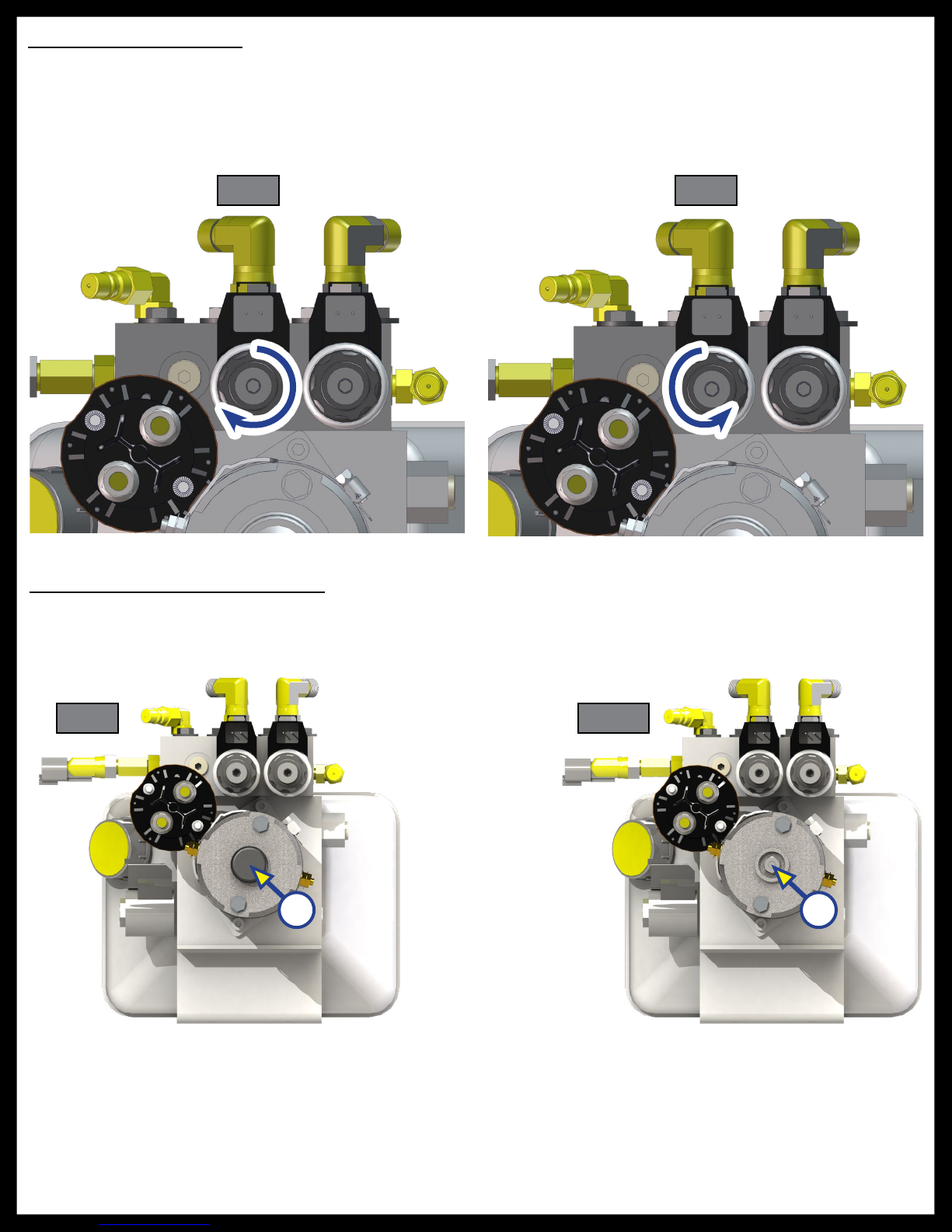
Manual Override - Jacks
In the event that the jacks will not extend or retract, the valves can be manually overridden by using a ⁄”
hex wrench to turn the manual override clockwise on the valve (See Fig. 7). The leveling jacks can then be
extended or retracted. Remember to turn the manual override completely counterclockwise (See Fig. 8)
until it will no longer turn to close the valve after the jacks have been completely extended or retracted. Do
not over-tighten override set screws, as this can damage the valves.
Fig. 7 Fig. 8
Clockwise for manual override
Counterclockwise for normal operation
Manual Override - Power System
The Lippert LCI Level-Up Motorhome Leveling System can be run with auxiliary power devices like cordless
or power drills. In the event of electrical or system failure, this manual method of extending and retracting
the jacks can be used. A standard handheld drill is all that is required. See the instructions below.
Fig. 9 Fig. 10
AA
1. Remove plastic cap (Fig. 9A).
2. Disconnect or shield power cables on the motor.
3. Using a ½” socket and auxiliary drive device, i.e. cordless or power drill, insert ½” socket onto coupler
found under plastic cap (Fig. 10A).
4. Run drill in reverse or counterclockwise to retract jacks.
Rev: 06.29.18
Page 12
CCD-0001535
Page 13

Automatic Safety Shutoff
If the control panel is left on and inactive for four minutes it will shut off automatically. To reset the system,
the coach ignition MUST be turned off, then back on, and the ON/OFF button MUST again be pushed.
Drive Away Protection System
If the ignition is in the “RUN” position, jacks are down, and the operator releases the parking brake, all
indicator lights will flash and the alarm beeper will activate. The system will then automatically retract the
jacks until the jacks are fully retracted or the operator resets the parking brake.
The power unit will also operate to keep the jacks retracted in the event the leveling system loses pressure
as the coach is being driven.
“Jacks Down" Alarm
The LCI Level-Up Motorhome Leveling System is designed to sound an alarm and illuminate the control
panel in the event of two (2) possible scenarios:
1. A “RETRACT” hose leaks.
2. The pressure holding the jacks in the retracted position falls to approximately 1500 psi to sound the
alarm. If the alarm sounds and the control panel illuminates and flashes while driving the vehicle:
A. Immediately find an area to safely pull the vehicle off of the roadway.
B. Set the PARKING BRAKE.
C. Inspect all jacks, hoses, and valves for leaks. If no leaks are observed:
I. Turn control panel “ON.”
II. Push “RETRACT ALL JACKS” button.
III. Wait until “JACKS DOWN” light and alarm are off.
IV. Inspect jacks. If jacks are retracted and no leaks are observed, vehicle can be driven.
NOTE: If system is leaking or alarm does not subside after applying the above procedure, disconnect wires
from pressure switch and proceed immediately to a service center. The pressure switch is a blue
and gold colored valve located on the power unit manifold identified by the spark proof style
connector with yellow and black wires. (See Page 6, Fig. 5).
NOTE: For prolonged travel to the service center, be sure to stop and check the disposition of the leveling
jacks every so often to make sure they are not extending.
Fluid Recommendation
The Lippert Electronic Leveling System is pre-filled, primed and ready to operate direct from the
manufacturer. Type “A” Automatic Transmission Fluid (ATF) is utilized and will work. ATF with Dexron III® or
Mercon 5® or a blend of both is recommended by Lippert Components, Inc.
In colder temperatures (less than 10° F) the jacks may extend and retract slowly due to the fluid’s molecular
nature. For cold weather operation, fluid specially formulated for low temperatures may be desirable. For a
list of approved fluid specifications, see TI-188.
Rev: 06.29.18
Page 13
CCD-0001535
Page 14

What Is Happening? Why? What Should Be Done?
System will not turn on
and On/Off indicator
light does not illuminate.
Control panel turns on
but turns off when jack
button is pushed or
displays "Low Voltage."
Control panel turns on,
coach will not auto level,
"Jacks Down" displayed,
jacks are retracted.
Jacks will not extend
to ground, pump is
running.
Coach ignition not in
RUN position.
Turn ignition to RUN position.
Parking brake not set. Set parking brake.
Controls have been
on for more than four
minutes and have timed
Turn ignition OFF and then back ON.
out.
Low voltage on battery. Start coach to charge battery.
Change fluid level in reservoir. If fluid is low, add
Low fluid level.
fluid to ½" from top of reservoir with jacks retracted.
If JACKS DOWN light remains on, call Lippert Service.
Little to no fluid in
reservoir.
Add fluid as recommended. See Page 13.
Leg valve is inoperative. Clean, repair or replace.
Electronic signal is lost
between control and
leg valves.
Trace wires for voltage drop or loss of signal. Repair
or replace necessary wires or replace control pad.
Any one or two jacks will
not retract.
"Jacks Retracted" does
not display when all
jacks are retracted.
Alarm sounds and
"Jacks Down" light starts
flashing while traveling,
jacks are fully retracted.
Jack bleeds down after
being extended.
Control panel powers
up, screen displays "Low
Voltage."
Hose damaged or
unconnected.
Replace with new hose or reconnect hose.
Valve inoperative. Replace inoperative valve.
Electronic signal is lost
between control and
solenoid.
Attempt to retract jacks in MANUAL mode. If
successful, replace control pad. If not, test for voltage
drop between control pad and leg valve. Repair bad
wiring or replace defective board or valve.
Low fluid level. Add fluid as recommended. See Page 13.
Retract press switch
inoperable.
Check connection or replace.
Low fluid level. Add fluid as recommended. See Page 13.
Retract press switch
inoperable.
Valve Manual Override
open.
Check connection or replace.
Close override. See Page 12, Fig. 8.
Engine not running. Start coach engine.
No power to control
panel
Auto level function does
not finish
Rev: 06.29.18
Tripped circuit breaker. Reset.
Ignition not ON. Turn ignition ON.
Error code "Unable to
Finish Leveling".
Move coach to a more level site.
Page 14
CCD-0001535
Page 15

Wiring Diagram
Touch Pad
Main Power Harness
Controller
Touch Pad Harness
Interconnect Harness
Rear Sensor Harness
Power Unit
Power Unit Harness
Directional
Valve
Pressure Switch
Rev: 06.29.18
Manifold
Page 15
Valve
CCD-0001535
Page 16

Plumbing Diagram
Right Front
Jack
Left Front
Jack
Retract
NOTE: Orange - Retract
Black - Extend
Power Unit
Right
Rear Jack
Left Rear
Extend
Rev: 06.29.18
Jack
Page 16
CCD-0001535
Page 17

12-PIN WIRE HARNESS
1. WHITE (CHASSIS
POWER)
2. BLACK w/
WHITE(PUMP
SOLENOID)
3. RED (CURBSIDE REAR
VALVE)
4. GREEN (ROADSIDE
FRONT VALVE)
5. YELLOW (PSI SWITCH)
Bill of Materials
Description Part # Details Quantity
Power Unit
6. BLUE (ROADSIDE
REAR VALVE)
7. BROWN (GROUND)
10
11
9
8. PURPLE (CURBSIDE
FRONT VALVE)
12
9. GREY (PUMP
SOLENOID)
1
10. AUX
11. AUX
2
3
4
12. AUX
196471 Hydraulic Power Unit, Leveling Only 1
175249 Hydraulic Power Unit, Leveling Only 1
8
7
6
5
293559 Hydraulic Power Unit, Leveling Only 1
Motor
Solenoid
179327 12V DC Motor for Power Unit 1
161394 Motor Solenoid 1
177094 Blocking Valve 4
Valve
259524 Directional Valve 1
Coil
Pressure Switch
Pump Harness
174184
142927 2150 PSI Rated Pressure Switch 1
178373 Electrical Harness for Power Unit 1
Electromagnetic Coil for Blocking
Valve
Main Harness 178375 30' Hydraulic Leveling Main Harness 1
Touch Pad - Controller
Harness
Remote Sensor Harness
178279
241314 Remote Sensor to Brain Harness 1
Electrical Harness between Touch
Pad & Controller
Brain 289252 Control Module 1
Touch Pad
Remote Sensor 294287
234802 Touch Panel mounted in Dash 1
Secondary Level Sensor mounted
rearward
433458 8k Leveling Jacks *
Hydraulic Jacks
236560 14k Leveling Jacks *
258550 20k Leveling Jacks *
5
1
1
Footpad
*Jack quantities will either be 2 or 4 depending on OEM specified design.
**Optional - Quantities will vary.
Rev: 06.29.18
113309 9” Footpad for Leveling Jacks 4
117238
12” Footpad for Leveling Jacks Optional
**
Page 17
CCD-0001535
Page 18
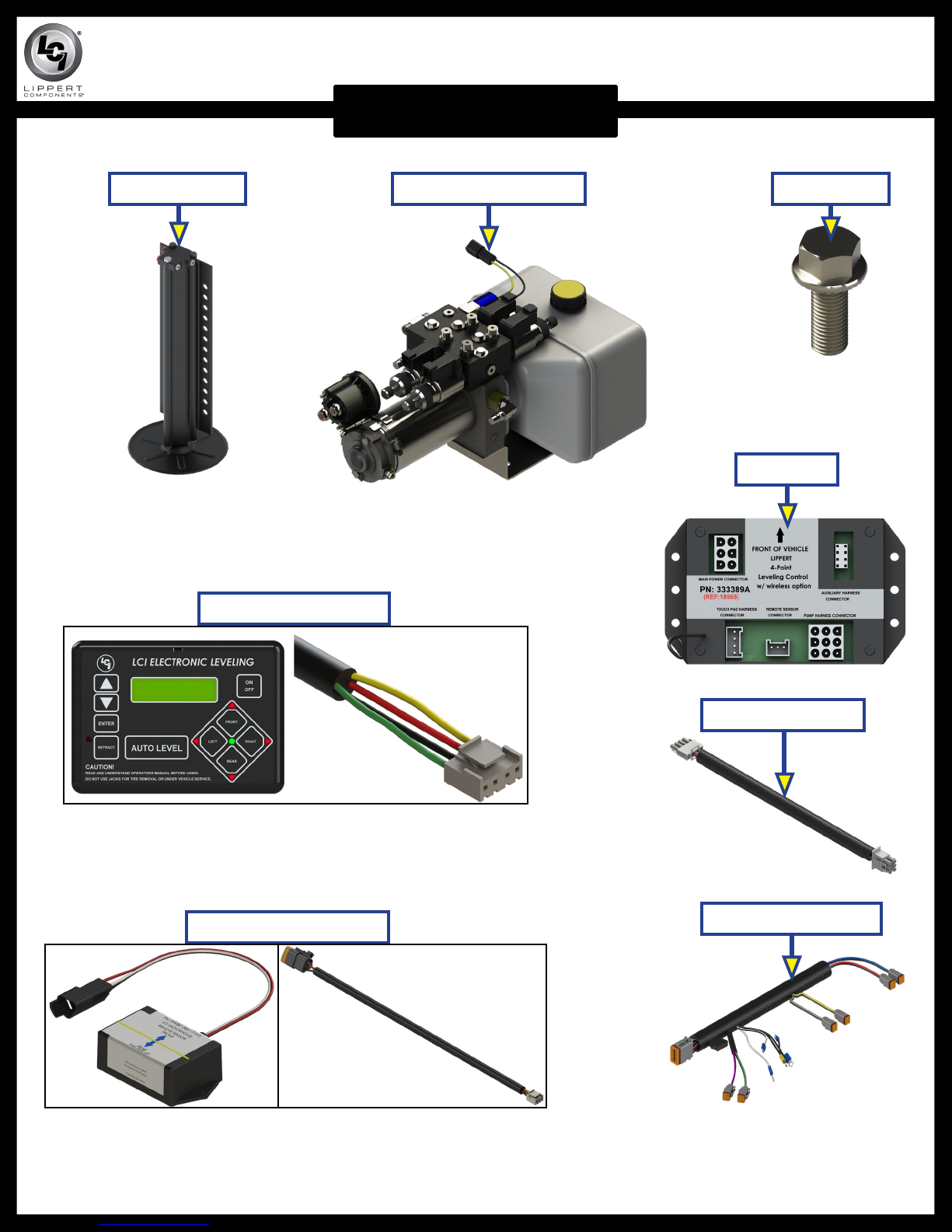
LEVEL-UP® MOTORIZED LEVELING
LEVELING AND STABILIZATION
Bolt; ½" x13Hydraulic Power UnitLeveling Jacks
Controller
Touch Pad & Harness
Rear Sensor & Harness
Auxiliary Harness
Power Unit Harness
Rev: 06.29.18
Page 18
CCD-0001535
Page 19

LEVEL-UP® MOTORIZED LEVELING
LEVELING AND STABILIZATION
A
C
D
B
Callout Part # Description
A
B
C
D
Rev: 06.29.18
196471 Hydraulic Power Unit, Leveling Only
175249 Hydraulic Power Unit, Leveling and Slides
179327 12V DC Motor for Power Unit
161394 Motor Solenoid
Page 19
CCD-0001535
Page 20

LEVEL-UP® MOTORIZED LEVELING
LEVELING AND STABILIZATION
E F
G
H
I
Callout Part # Description
E 195860 8K Jack
F
G
236560 14K Jack
258550 20K Jack
H 113309 9” Footpad for Leveling Jacks
I 117238 12” Footpad for Leveling Jacks - Optional
Rev: 06.29.18
Page 20
CCD-0001535
Page 21

LEVEL-UP® MOTORIZED LEVELING
LEVELING AND STABILIZATION
J
L
K
M
N
O
P
Q
Callout Part # Description
J
K
333389 Controller
234802 LCD Touch Pad
L 294287 Rear Sensor
M
N
178373 Power Unit Harness
241314 Rear Sensor Harness
O *178375 Main Harness (Winnebago Only)
P
Q
R
178279 Touch Pad Harness
178372 Main Harness
140524 Chassis Harness
NOTE: Parts shown with an asterisk (*) are for reference only.
The part is not available for individual replacement.
R
Rev: 06.29.18
Page 21
CCD-0001535
Page 22

LEVEL-UP® MOTORIZED LEVELING
LEVELING AND STABILIZATION
W
T
U
X
S
V
Callout Part # Description
S *115567 Weld-On Jack Mounting Bracket
T 116471 Weld-On Jack Mounting Bracket
U 134989 Weld-On Jack Mounting Bracket
V 162349 Weld-On Jack Mounting Bracket
W
X
NOTE: Parts shown with an asterisk (*) are for reference only.
The part is not available for individual replacement.
Rev: 06.29.18
100345 Weld-On Jack Mounting Bracket
1170591 Bolt-On Jack Mounting Bracket
Page 22
CCD-0001535
Page 23

LEVEL-UP® MOTORIZED LEVELING
LEVELING AND STABILIZATION
Y
Z
AC
AA
AB
Original Current
Callout Part # Description
Y
Z
AA
174184 12 Volt Deutsch Style Coil (Hydac)
140571 Isolator Valve
177094 Hydac Valve
AB *259524 Directional Valve
Pressure Switch (2150 PSI) (Original, No Longer Available)
AC
142927
Pressure Switch (2150 PSI) (Current)
NOTE: Parts shown with an asterisk (*) are for reference only. The part is not available for
individual replacement.
Rev: 06.29.18
Page 23
CCD-0001535
Page 24

LEVEL-UP® MOTORIZED LEVELING
LEVELING AND STABILIZATION
AD
AI
AE
AJ
AF
AK
AG
AL
AH
AM
AN
AO
Callout Part # Description
AD
AE
AF
AG
AH
AI
AJ
AK
AL
AM
AN
AO
140457 Quick Disconnect Fitting
141321 O-Ring to Pipe Straight Reducer Fitting
141109 Straight Face Seal Fitting
143108 Branch T-Fitting
141087 Face Seal T-Fitting
156846 Swivel Face Seal Elbow 90 Degree Fitting
141610 Face Seal Elbow 90 Degree Fitting
141331 Elbow 90 Degree Fitting
141323 ½" Hex Plug
140998 ¼" Hex Plug
118076 Bolt; ½" - 20 x 1 ½"
178210 Flange Nut, ½" - 20
Rev: 06.29.18
Page 24
CCD-0001535
Page 25

Notes
Rev: 06.29.18
Page 25
CCD-0001535
Page 26

The contents of this manual are proprietary and copyright protected by Lippert Components, Inc. (“LCI”).
LCI prohibits the copying or dissemination of portions of this manual unless prior written consent from an
authorized LCI representative has been provided. Any unauthorized use shall void any applicable warranty.
The information contained in this manual is subject to change without notice and at the sole discretion of LCI.
Revised editions are available for free download from lci1.com.
Please recycle all obsolete materials.
For all concerns or questions, please contact
Lippert Components, Inc.
Ph: (574) 537-8900 | Web: lci1.com | Email: customerservice@lci1.com
Rev: 07.02.2018 Level-Up® Motorized Leveling LCD Owner's Manual
 Loading...