

Page 1

Hydraulic Through Frame Slideout
OWNER'S MANUAL
Rev: 07.09.2014
Page 1
Hydraulic Through Frame Slideout Owners Manual
Page 2

TABLE OF CONTENTS
Warning, Safety, and System Requirement Information 4
Description 4
Safety Information 4
Prior to Operation 5
Operation 5
Extending Slideout Room 5
Retracting Slideout Room 5
Maintenance 6
Inspection 6
System Maintenance 6
Electrical System Maintenance 6
Mechanical Maintenance 6
Troubleshooting 7
Troubleshooting Introduction 7
Hydraulic slideout cylinder retract test 8
Hydraulic slideout cylinder extend test 8
Fluid Filling Procedure 9
Comparing 14.5° and 20° Rack and Pinion Gears 10
Gear Pack Replacement Instructions 11
Corrective Action for Squeaking Gear Packs 12
Motor troubleshooting 13
Wiring Diagram 14
Room Bar Measurement Chart 15
Adjusting room so it seals in the IN position 16
Adjusting room so it seals in the OUT position 16
Mechanical Room Adjustment 17
Horizontal adjustment 17
Vertical adjustment 17
Synchronizing Room Travel 17
Extend and retract cylinder port locations 18
Manual Override 18
Rev: 07.09.2014
Page 2
Hydraulic Through Frame Slideout Owners Manual
Page 3

2x2 Hydraulic Through Frame Slideout Assembly 19
2x2 Hydraulic Through Frame Slideout Components 20
2x2 Hydraulic Through Frame Slideout Components 21
2x2 Hydraulic Through Frame Slideout Components 22
2x2 Hydraulic Through Frame Slideout Drive Components 23
2x3 Hydraulic Through Frame SLideout Assembly 24
2x3 Hydraulic Through Frame Slideout Assembly 25
2x3 Hydraulic Through Frame Slideout Components 26
2x3 Hydraulic Through Frame Slideout Drive Components 27
2.5x2.5 Hydraulic Through Frame Slideout Assembly 28
2.5x2.5 Hydraulic Through Frame Slideout Components 29
2.5x2.5 Hydraulic Through Frame Head Assemblies (Standard) 30
2.5x2.5 Hydraulic Through Frame Head Assemblies (V-Tech) 31
2.5x2.5 Hydraulic Through Frame Slideout Components 32
2.5x2.5 Hydraulic Through Frame Slideout Drive Components 33
Notes 34
Rev: 07.09.2014
Page 3
Hydraulic Through Frame Slideout Owners Manual
Page 4

Warning, Safety, and System Requirement Information
Description
The Lippert Hydraulic Through Frame Slideout System is a rack and pinion guide system, utilizing a hydraulic
cylinder to move the room assembly. The power unit drives the cylinder rod in a forward and backward motion to
move the slide room in and out. The Lippert Hydraulic Slideout System is designed to operate as a negative ground
system.
Safety Information
The “WARNING” symbol above is a sign that a service or maintenance procedure has a safety risk involved and may
cause serious injury or death if not performed safely and within the parameters set forth in this manual.
Always wear eye protection when performing service or maintenance to the vehicle. Other safety equipment to
consider would be hearing protection, gloves and possibly a full face shield, depending on the nature of the service.
This manual provides general service and maintenance procedures. Many variables can change the circumstances
of the service procedure, i.e., the degree of difficulty involved in the service operation and the ability level of the
individual performing the operation. This manual cannot begin to plot out procedures for every possibility, but will
provide the general instructions for effectively servicing the vehicle. In the event the skill level required is too high
or the procedure is too difficult, a certified technician should be consulted before performing the necessary service.
Failure to correctly service the vehicle may result in death, serious injury or voiding the warranty. The owner’s
manual for the unit may have more procedures for service and maintenance.
Failure to act in accordance with the following may result in death, serious injury, coach or property
damage.
The Lippert Hydraulic Through Frame Slideout System is intended for the sole purpose of extending and retracting
the slideout room. Its function should not be used for any other purpose or reason than to actuate the slideout
room. To use the system for any reason other than what it is designed for may result in damage to the coach and/
or cause serious injury or even death.
Before actuating the system, please keep these things in mind:
1. Parking locations should be clear of obstructions that may cause damage when the slideout room is
actuated.
2. Be sure all persons are clear of the coach prior to the slideout room actuation.
3. Keep hands and other body parts away from slideout mechanisms during actuation. Severe injury or
death may result.
4. To optimize slideout actuation, park coach on solid and level ground.
Rev: 07.09.2014
Page 4
Hydraulic Through Frame Slideout Owners Manual
Page 5
Prior to Operation
Prior to operating the Lippert Hydraulic Through Frame Slideout System, follow these guidelines:
1. Coach should be parked on the most level surface available.
2. Leveling or stabilizing system should be actuated to ensure coach will not move during operation of
slideout system.
3. Be sure battery is fully charged.
4. Be sure to keep all persons and pets clear of slideout system during operation.
Always make sure that the slideout room path is clear of people and objects before and during operation
of the slideout room. Always keep away from the slide rails when the room is being operated. The gear
assembly may pinch or catch on loose clothing causing personal injury.
NOTE: Install transit bars (if so equipped) on the slideout room during storage and transportation.
Operation
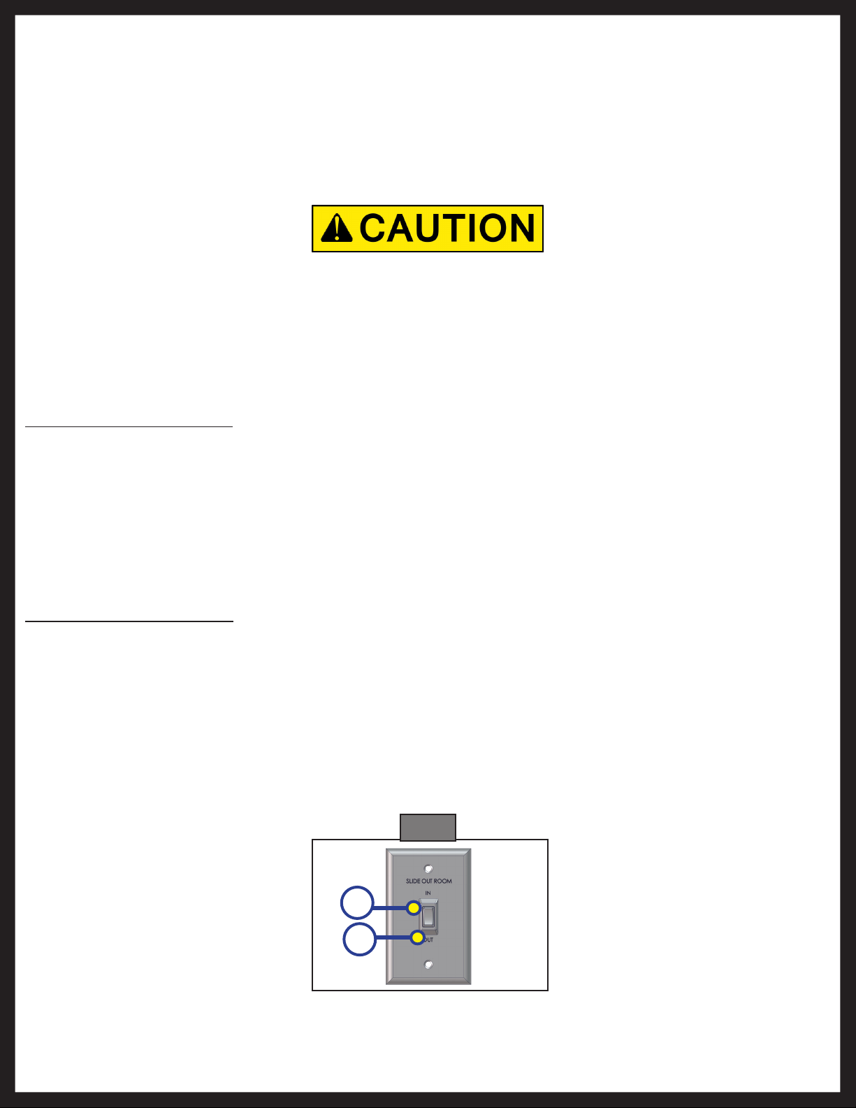
Extending Slideout Room
5. Level the Unit.
6. Verify the battery is fully charged and hooked up to the electrical system.
7. Remove transit bars (if so equipped).
8. Press and hold the IN/OUT switch in the OUT position until room is fully extended and stops moving.
9. Release switch, which will lock the room into position.
NOTE: Only hold OUT switch until room stops.
Retracting Slideout Room
1. Verify the battery is fully charged and hooked up to the electrical system.
2. Press and hold the IN/OUT switch in the IN position until the room is fully retracted and stops moving.
3. Release the switch. This will lock the room into position.
NOTE: Only hold IN switch until room stops.
4. Install the transit bars (if so equipped).
Fig. 1
Rev: 07.09.2014
A
B
Page 5
Hydraulic Through Frame Slideout Owners Manual
Page 6

Maintenance
Inspection
After servicing the slideout system in any way, be sure to check the following:
1. Slideout stops are installed and adjusted properly.
2. Head assemblies are installed and adjusted properly.
3. System is mounted properly.
4. Cross shafts are mounted properly and clear all other components.
5. Gear packs function properly.
6. Manual override is accessible.
7. Outside seals compress when slideout is retracted.
8. Inside seals compress when slideout is extended.
9. Slideout extends and retracts smoothly.
10. Both sides of slideout are synchronized.
11. Any dirt or debris is cleaned from the interior or exterior of the coach.
System Maintenance
The Lippert Through Frame Slideout System has been static tested to over 4,000 continuous cycles without
any noticeable wear to rotating or sliding parts. It is recommended that when operating in harsh environments
(road salt, ice build up, etc.) the moving parts be kept clean. They can be washed with mild soap and water. No
grease or lubrication is necessary and in some situations may be detrimental to the environment and long term
dependability of the system.
Electrical System Maintenance
For optimum performance, the slideout system requires full battery current and voltage. The battery must be
maintained at full capacity. Other than good battery maintenance, check the terminals and other connections at
the battery, the control switch, and the system for corrosion, and loose or damaged terminals. Check motor leads
under the trailer chassis. Since these connections are subject to damage from road debris, be sure they are in good
condition.
NOTE: The Lippert Through Frame Slideout System is designed to operate as a negative ground system.
A negative ground system utilizes the chassis frame as a ground and an independent ground
wire back to battery is necessary. It is important that the electrical components have good wire to
chassis contact. To ensure the best possible ground, a star washer should be used. Over 90% of
unit electrical problems are due to bad ground connections.
Mechanical Maintenance
Although the system is designed to be almost maintenance free, actuate the room once or twice a month to keep
the seals and internal moving parts lubricated. Check for any visible signs of external damage after and before
movement of the travel trailer.
NOTE: For long-term storage: It is recommended that the room be closed (retracted).
Rev: 07.09.2014
Page 6
Hydraulic Through Frame Slideout Owners Manual
Page 7

Troubleshooting
Troubleshooting Introduction
This troubleshooting chart outlines some common problems, their causes and possible corrective actions. If any
part or serial number information is available, provide it to the service technician when asking for assistance.
The Lippert Slideout System is only one of four interrelated slideout room system components. These four
components are: chassis, room, coach, and Lippert Slideout System. Each one needs to function correctly with the
others or misalignment problems will occur.
Every travel trailer has its own personality and what may work to fix one trailer may not work on another even if the
symptoms appear to be the same.
When something restricts room travel, system performance will be unpredictable. It is very important that slide
tubes be free of contamination and allowed to travel full distance (Stroke). Ice or mud buildup during travel is an
example of some types of contamination that can occur.
When you begin to troubleshoot the system, make sure the battery is fully charged, there are no visible signs of
external damage to the system and that all connections are secure.
During troubleshooting, remember that if you change something, that change may affect something else. Be sure
any changes you make will not create a new problem.
You can obtain additional information on the Lippert Slideout System by visiting www.lci1.com/customerservice or
by calling 574-537-8900.
Problem Probable Cause Corrective Action
Restriction or obstruction inside or
outside of unit
Check for and clear obstruction
Check battery voltage and charge
Room doesn't move when switch is
pressed
Low battery voltage, blown fuse,
defective wiring
if needed. Find and check fuse,
replace if blown. Check battery
terminals and wiring. Look for
loose, disconnected or corroded
connectors.
Power unit runs but room does not
move
Power unit runs, room moves slowly
Room drifts in both the in and out
positions
Restrictions both inside and outside
of unit
Low battery, poor ground, extremely
low outdoor temperature
Check for leaks in the hydraulic
system
Air in system
Check for and clear restriction
Charge battery and check ground
wire
Tighten fittings
After checking all connections, cycle
pump several times in and out
Leaking cylinder seal See cylinder test next page
Fluid bypassing cylinder piston See cylinder test next page
In the closed position, room drifts
out
Hose from pump is leaking Tighten fitting or replace hose
Air in system
After checking all connections, cycle
pump several times in and out.
Loose mounting bolts Tighten mounting bolts.
Hose from pump is leaking Tighten fitting or replace hose
In the open position, room drifts in
Leaking cylinder seal See cylinder test on next page
Fluid bypassing cylinder piston See cylinder test on next page
Rev: 07.09.2014
Page 7
Hydraulic Through Frame Slideout Owners Manual
Page 8

Hydraulic slideout cylinder retract test
1. Retract (close) all slideouts (rooms) completely.
2. Disconnect all rooms from system (if coach is equipped with IRC, close all but one room).
3. Loosen hose from "E" (extend) port on the manifold of the power unit.
4. Plug opening on manifold to prevent drawing air into the system.
Do not attempt to run room out with the "E" port hose loose. The system will experience rapid fluid loss.
5. Energize the pump unit to retract (close) room.
6. When room is fully retracted, continue to run the room in and watch for fluid flow from hose/port "E".
Fluid flow greater than a few drops will indicate internal cylinder leaking (bypassing of piston seal). If
greater than a few drops leak from hose fitting, piston seal is bad and will need to be replaced. If there
is no fluid flow, reconnect hose to "E" port and tighten.
7. Repeat steps 2 through 6 for each slideout until all slideouts have been tested. Energize the pump unit
to retract (close) room.
Be sure to reconnect and tighten hose at the "E" port before attempting to extend (open) the room or the
system will experience rapid fluid loss.
Hydraulic slideout cylinder extend test
1. Extend (open) all slideouts (rooms) completely.
2. Disconnect all rooms from system (if coach is equipped with IRC, open all but one room).
3. Loosen hose from "R" (retract) port on the manifold of the power unit. Individual slideouts can be
tested if the unit is equipped with an IRC block. Close all valves in IRC except the one to be tested.
4. Plug opening on manifold to prevent drawing air into the system.
Do not attempt to run room in (retract) with the "R" port hose loose. The system will experience rapid
fluid loss.
5. Energize the pump unit to extend (open) room.
6. Continue to run the room out and watch for fluid flow from hose/port "R" (or IRC block if coach is
equipped with IRC). Fluid flow greater than a few drops will indicate internal leaking (bypassing of
piston seal). If greater than a few drops leak from hose fitting, piston seal is bad and will need to be
replaced. If there is no fluid flow, reconnect hose to "R" port and tighten.
7. Repeat steps 2 through 6 for each slideout until all slideouts have been tested.
Be sure to reconnect and tighten hose at the "R" port before attempting to retract (close) the room or the
system will experience rapid fluid loss.
Rev: 07.09.2014
Page 8
Hydraulic Through Frame Slideout Owners Manual
Page 9
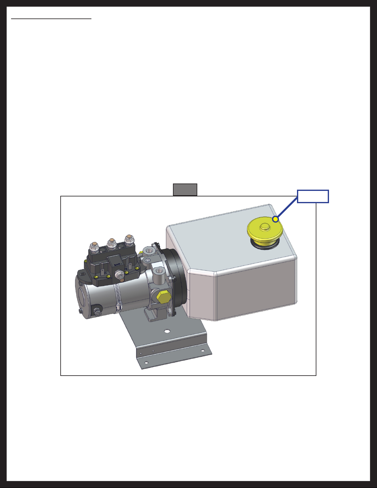
Fluid Filling Procedure
The Lippert Hydraulic Slideout System uses automatic transmission fluid (ATF). Any ATF can be used. A full
synthetic or synthetic blend works best such as Dexron III or Mercon 5. For best operation, fill system to within ½”
of the top when all slideouts are completely retracted. The see-through reservoir makes it easy to check oil level. It
is recommended that the oil level be checked prior to operating the system. Make sure the breather cap is free of
contamination before removing, replacing or installing.
1. Remove Breather/Fill Cap.
2. Pour ATF into Breather/Fill opening.
NOTE: Do not allow any contamination into reservoir during fill process.
NOTE: Standard reservoir holds approximately 2 quarts (1.89 liters) of ATF.
3. Fill to within ½” of top.
4. Replace Breather/Fill cap when finished.
NOTE: System is self-purging. By simply cycling the system 2-3 times, any air in the system will be forced
back to the reservoir and out of the Breather/Fill cap.
Fig. 1
Fill Cap
Rev: 07.09.2014
Page 9
Hydraulic Through Frame Slideout Owners Manual
Page 10
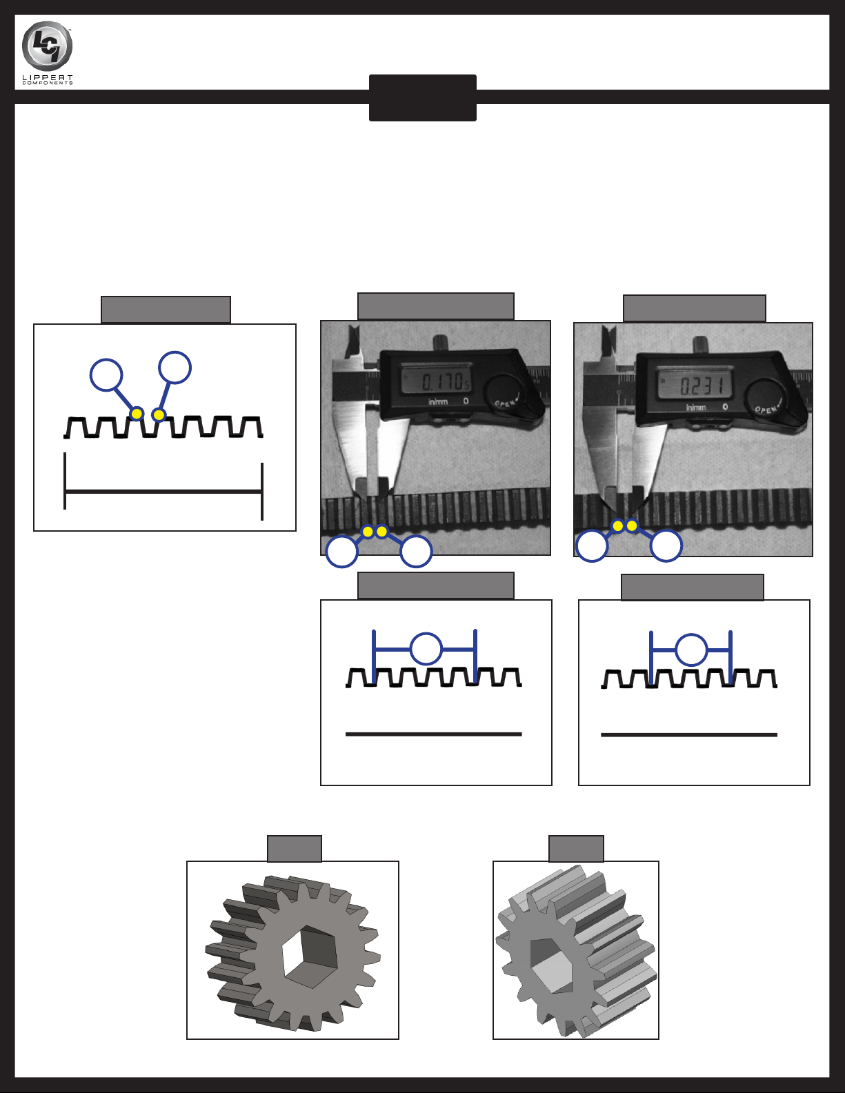
COMPARING 14.5° AND 20° RACK AND PINION GEARS
SLIDEOUTS
1. Start by measuring the distance between two individual adjacent teeth.
2. Using calipers or a steel rule, measure from the inside edge of one tooth (A), and then measure over to
the inside edge of the next tooth (B) shown in (Fig. 1).
3. The 14.5° rack will measure approximately 0.170 inches (Fig. 2.1). The 20° rack will measure
approximately 0.231 inches (Fig. 3.1).
4. The 14.5° rack will have 4 teeth per inch (Fig 2.2). The 20° rack will have 3 teeth per inch (Fig 3.2).
Fig. 1 Side View
A
B
Fig. 2.1 - 14.5° Rack
A
B
Fig. 2.2 - 14.5° Rack
1"
Fig. 3.1 - 20° Rack
A
B
Fig. 3.2 - 20° Rack
1"
4 teeth per inch
3 teeth per inch
The simplest way to differentiate between the 14.5° spur gear and the 20° spur gear is the number of teeth on the
gear. Spur gear 122739 (Fig. 4) has 18 teeth. Spur gear 101941 (Fig. 5) has 15 teeth.
Fig. 4 Fig. 5
Rev: 07.09.2014
Page 10
Hydraulic Through Frame Slideout Owners Manual
Page 11
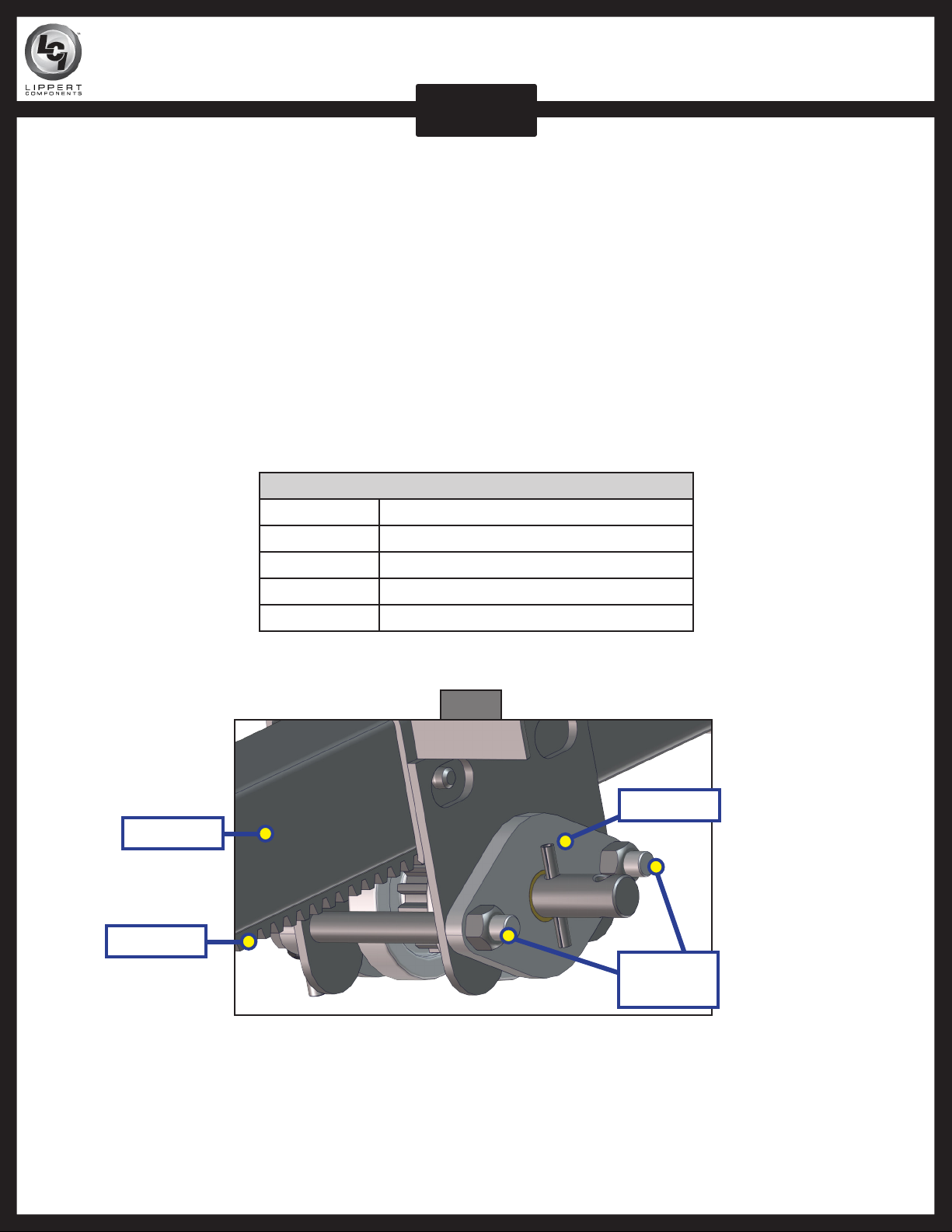
GEAR PACK REPLACEMENT INSTRUCTIONS
SLIDEOUTS
In the event a gear pack needs to be replaced, follow these steps:
1. Run slideout room half way out.
2. Place a jack under the inner arm of the slideout.
3. Jack room up just enough to remove pressure off the gear pack.
4. Remove drive bolt from the cross shaft.
5. Remove bolts which hold the gear pack assembly in place on the outer rail.
6. Drop out the damaged gear pack.
7. Install the new gear pack.
8. Install bolts to hold gear pack assembly in place on the outer rail.
9. Install cross shaft and bolt.
10. Gear pack assembly does not need to be torqued down, only adequately and securely tightened.
Gear Packs
281331 2 x 2
140409 2 x 3, 3 x 3
122837 Standard 2.5 x 2.5
123356 Heavy Duty 2.5 x 2.5
140418 Embedded Rack
Outer Rail
Gear Rack
Fig. 1
Gear Pack
Mounting
Bolts
Rev: 07.09.2014
Page 11
Hydraulic Through Frame Slideout Owners Manual
Page 12

CORRECTIVE ACTION FOR SQUEAKING GEAR PACKS
SLIDEOUTS
Fig. 1
Fig. 2
A
A
B
Fig. 3 Fig. 4
A
A
B
C
1. Loosen both gear packs bolts (Fig. 1A and Fig. 1B) until tension is off of the gear pack.
2. Using a manual pump oil can, pump 2-3 squints of synthetic motor oil onto gear pack drive shaft in
lubrication points (Fig. 2A), (Fig. 3A), (Fig. 4 A through D).
NOTE: Do not lubricate rack or pinion gear teeth, lubricate drive shaft only.
NOTE: LCI recommends Mobile One Fully Synthetic 10W-30 Motor Oil to lubricate gear pack.
3. Extend and retract slideout arms several times to work lubricant through gear pack.
D
Rev: 07.09.2014
Page 12
Hydraulic Through Frame Slideout Owners Manual
Page 13

Motor troubleshooting
Before attempting to troubleshoot the motor, make sure an adequate power source is available. The unit batteries
should be fully charged or the unit should be plugged into A/C service with batteries installed. Do not attempt to
troubleshoot the motor without assuring a full 12V DC charge.
The following tests require only a DC voltmeter (or DC test light) and a jumper lead.
1. Attach voltmeter (or test light) leads to the negative and positive switch terminals on back of wall
switch. Does the meter indicate 12V DC? If YES, see Step 2; if NO see Step 3.
2. If YES, at the motor, check the incoming leads to 12V DC (if necessary, disconnect leads at wire splices).
Does meter indicate 12V DC? If YES, motor needs to be replaced. The motor is not field serviceable.
DO NOT ATTEMPT TO REPAIR. If NO, Inspect all wires and connections between the wall switch and
the motor. Repair connections as necessary. Recheck as in Step 1.
3. If NO, Inspect all connections between battery and switch. Inspect 30A Auto-reset Circuit Breaker (See
Next Page). Recheck as above in Step 1.
4. Since there are no field serviceable parts in the motor, electrical troubleshooting and service is limited
to replacing only those components as previously outlined.
5. Thorough inspection of wiring and connections is the only other electrical service that can be
performed.
Fig. 1 Slideout Switch Color Codes
Red Jumper
Black Jumper
Green
Yellow
Black with
Black Jumper
Black - Power
Green - Motor CCW
Yellow - Motor CW
Red - Motor CW
Red with Red Jumper
Rev: 07.09.2014
Page 13
Hydraulic Through Frame Slideout Owners Manual
Page 14

Wiring Diagram
In
Switch - Wall switch
wired the same way
and pump switch get
Yellow
Reservoir
Out
Red "Hot"
Customer's
Green
source
choice 12VDC
polarity
Change of
reverses motor
Solenoid
Duel Polarity
Manufacturer
Supplied Breaker
Manifold
Battery
Motor
Rev: 07.09.2014
Page 14
Hydraulic Through Frame Slideout Owners Manual
Page 15

ROOM BAR MEASUREMENT CHART
SLIDEOUTS
Instructions:
1. Circle which side of your coach this room bar is for (Door Side or Off Door Side).
2. Enter the measurements for A, B, C, and D on the lines at the bottom.
DOOR SIDE
FRONT OF COACH
OFF DOOR SIDE
Room Bar
A
Room Bar
D
C
B
Rev: 07.09.2014
Brackets
A________ B________ C________ D________
Page 15
Hydraulic Through Frame Slideout Owners Manual
Page 16

Adjusting room so it seals in the IN position
1. Locate cylinder coming through the frame.
2. Run room partially out.
3. Hold Jam nut (Fig. 1A) in place with wrench.
4. Adjust Nylock nut (Fig. 1C) towards the bracket if the room does not seal or adjust the Nylock nut
(Fig. 1C) away from the bracket if the room is too tight and damages the fascia.
NOTE: Make small adjustments running the room in after each adjustment until proper seal is achieved.
Adjusting room so it seals in the OUT position
1. Locate cylinder coming through the frame.
2. Extend room completely out.
3. Check the inside fascia and seal positioning.
4. Partially retract room.
5. Loosen Jam nut (Fig. 1A) from Jam nut (Fig. 1B) and back off Jam nut (Fig. 1A) to give Jam nut (Fig. 1B)
room for adjustment.
6. Adjust Jam Nut (Fig. 1B) away from the bracket if the room extends to far and damages the inside
fascia or adjust Jam Nut (Fig. 1B) towards the bracket if the room does not seal.
NOTE: Make small adjustments running the room out after each adjustment until proper seal is achieved.
7. Tighten Jam Nut (Fig. 1A) to Jam Nut (Fig. 1B).
Fig. 1
A
C
B
2" - 3"
Free Travel
Rev: 07.09.2014
Page 16
Hydraulic Through Frame Slideout Owners Manual
Page 17

Mechanical Room Adjustment
NOTE: All slideout room adjustments must be performed by certified service technicians. Adjustments
made by non-certified persons may void any and all warranty claims.
Horizontal adjustment
1. Loosen carriage bolts (Fig. 2A) on each bracket located at the end of each guide tube.
2. Room is ready to be positioned horizontally by pushing on the outside, sidewall or by using a prying
device inserted into the opening between the room and coach.
NOTE: Use caution when using prying device so seals do not become damaged.
Vertical adjustment
1. Loosen 2 carriage bolts (Fig. 2A) on each bracket located at the end of each guide tube.
2. Loosen jam nut.
3. For vertical adjustment turn vertical adjustment bolt (Fig. 3A) up or down to locate room height.
4. Once room is located, tighten carriage bolts (Fig. 2A) and Jam Nut bolts.
Fig. 2
A
A
Fig. 3
Jam Nut
Synchronizing Room Travel
The Lippert Hydraulic Slideout System room travel (both sides of the room traveling the same distance) can be
adjusted with specially designed synchronizing bracket mounted on the passive slide tube. The passive slide tube is
the one that is not powered. The active slide tube is the one that has the cylinder attached. If one side of the room
fails to seal adjust as follows:
1. Loosen bolts (Fig. 4A) on top of the passive slide tube (Fig. 4B).
2. Push or pull room (on the passive side) to align with the active side.
Rev: 07.09.2014
Fig.4
A
B
Page 17
A
Hydraulic Through Frame Slideout Owners Manual
Page 18

Extend and retract cylinder port locations
Standard Slideout Cylinder
Retract
Rod End Piston Rod
Retract
Rod End Piston Rod
Extend
Cap End Stud
Trunnion Slideout Cylinder
Extend
Cap End Stud
Manual Override
The Lippert Hydraulic Slideout System can be run with auxiliary power devices like electric drills, ratchet wrenches
or cordless screwdrivers. In the event of electrical or system failure, this manual method of extending and retracting
the slideout room can be used. A standard hand-held drill is all that is required. A standard 38" room will take
approximately 45 seconds to retract. See the instructions below.
1. Remove protective label (Fig. 1).
2. Using a standard hex bit, insert into auxiliary drive device (cordless drill, screwdriver, or ratchet
wrench).
3. Insert hex bit into coupler found under protective label (Fig. 2).
4. Run drill forward or clockwise to extend slideout room and in reverse or counterclockwise to retract
slideout room.
Fig. 1 Fig. 2
Rev: 07.09.2014
Page 18
Hydraulic Through Frame Slideout Owners Manual
Page 19

2X2 HYDRAULIC THROUGH FRAME SLIDEOUT ASSEMBLY
SLIDEOUTS
Outer Tube Assembly
Inner Tube Assembly
Head Assembly
Wear Pad
Roller Shaft
Stiffener
Hat
Gear Pack Assembly
Rear Roller
Inner Tube
Assembly
Rev: 07.09.2014
Page 19
Spur Gear
2x2 Hydraulic Through Frame Slideout Webpage
Page 20

2X2 HYDRAULIC THROUGH FRAME SLIDEOUT COMPONENTS
SLIDEOUTS
A
E
F
B
G
C
D
H
J
K
L
I
Callout Part # Description
A 103480 Wear Pad (x8)
B 277882 Wear Tab for 317322
C 104475 Rear Roller
D 105893 Roller Shaft
E 281331 Gear Pack
F 101941 Spur Gear (Current)
G 122739 Spur Gear (Obsolete)
H 102357 Stiffener
I 106059 Hat (x2)
J 113535 Front Trunion Bracket
K 106040 Rear Trunion Bracket
L 159279 Trim Plate
Rev: 07.09.2014
Page 20
2x2 Hydraulic Through Frame Slideout Webpage
Page 21

2X2 HYDRAULIC THROUGH FRAME SLIDEOUT COMPONENTS
SLIDEOUTS
D
B
C
A
F
G
E
NOTE: See Room Bar Measurement Chart
(LIP Sheet 0080)
Rev: 07.09.2014
Callout Part # Description
A 104851 Slideout Mounting Bracket
B 141792 1 3/8" Adjustable Head Assembly
C 159624 Standard Weld-On Head Assembly
D 163049 Flush Adjustable Head Assembly
E 173593 Standard Flush Fixed Head Assembly
F 173594 Standard Flush Adjustable Head Assembly
G
183949 Room Bar (Use for up to 80")
183950 Room Bar (Use for up to 154")
NOTE: Brackets can be shipped loose.
Page 21
2x2 Hydraulic Through Frame Slideout Webpage
Page 22

2X2 HYDRAULIC THROUGH FRAME SLIDEOUT COMPONENTS
SLIDEOUTS
A
B
C
D
E
F
G
Callout Part # Description
A
145735 Outboard Outer Arm (Idler)
145734 Outboard Outer Arm (Drive)
B 145736 Outboard Inner Arm
C 173204 Inboard Outer Arm 76" (Idler and Drive)
D 163778 Inboard Inner Arm
E 161014 Inboard Outer Arm 69" (Idler and Drive)
F 159389 Inboard Outer Arm 70" (Idler and Drive)
G 301393 Inboard Inner Arm (18 Teeth)
H 296090 Outboard Inner Arm (18 Teeth)
NOTE: Standard slideout arms have 15 teeth.
H
Rev: 07.09.2014
Page 22
2x2 Hydraulic Through Frame Slideout Webpage
Page 23

2X2 HYDRAULIC THROUGH FRAME
SLIDEOUT DRIVE COMPONENTS
SLIDEOUTS
A
C
D
B
E
Rev: 07.09.2014
F
Callout Part # Description
A 123603 Hydraulic Trunion 38"
B 125653 Hydraulic Trunion 24"
C 133874 Hydraulic Trunion 30"
D 141109 O-Ring Face Seal Straight Fitting
E 173738 O-Ring Face Seal Elbow Fitting
F 120639 Hydraulic Interior Slideout Switch
G 140530 6 Prong Interior Switch with Wall Plate
Page 23
G
2x2 Hydraulic Through Frame Slideout Webpage
Page 24

2X3 HYDRAULIC THROUGH FRAME SLIDEOUT ASSEMBLY
PRODUCT CATEGORY
2 x 3 Shorty Hydraulic Slideout
Hydraulic Cylinder
Cylinder Mounting Bracket
Inner Arm
Assembly
Front Roller
Assembly
Wear Tab
Outer Arm Assembly
Roller
Rod & Pin
Section Assembly
Rear
Roller
Roller
Shaft
Rev: 07.09.2014
Page 24
Front
Roller
2x3 Hydraulic Through Frame Slideout Webpage
Page 25

2X3 HYDRAULIC THROUGH FRAME SLIDEOUT ASSEMBLY
SLIDEOUTS
2 x 3 Bolt-In Hydraulic Slideout
See Page 1 for
Component
Descriptions
See Page 1 for
Component
Descriptions
2 x 3 Full Wall Hydraulic Slideout
Idler Arm
Rev: 07.09.2014
Page 25
2x3 Hydraulic Through Frame Slideout Webpage
Page 26

2X3 HYDRAULIC THROUGH FRAME SLIDEOUT COMPONENTS
SLIDEOUTS
A
B
D
G
C
H
Callout Part # Description
E
F
201709 16" Stroke Outer Arm Assembly
201708 30 ½" Stroke Outer Arm Assembly
A
I
158564 31 ½" Stroke Outer Arm Assembly
213654 36" Stroke Outer Arm Assembly
203468 30" Full Wall Drive Arm Outer Assembly
203470 30" Full Wall Passive Arm Outer Assembly
179024 16" Stroke Inner Arm Assembly
179124 30 ½" Stroke Inner Arm Assembly
B
158565 31 ½" Stroke Inner Arm Assembly
213655 36" Stroke Inner Arm Assembly
157692 30" Full Wall Drive Arm Inner Assembly
157294 30" Full Wall Passive Arm Inner Assembly
J
C 135435 Roller Assembly
D 101255 Roller
E 104474 Rear Roller
F 128926 Rod
G 118174 Roll Pin
H 105895 Roller Shaft
K
I 103480 Wear Tab
J 115034 Cylinder Mounting Bracket
K 115035 Cylinder Mounting Bracket
Rev: 07.09.2014
Page 26
2x3 Hydraulic Through Frame Slideout Webpage
Page 27

2X3 HYDRAULIC THROUGH FRAME
SLIDEOUT DRIVE COMPONENTS
SLIDEOUTS
A
E
B
F
C
D
G
Rev: 07.09.2014
H
Callout Part # Description
A 120639 Hydraulic Interior Switch
B 140530 6 Prong Interior Switch with Wall Plate
C 173738 O-Ring Face Seal Elbow Fitting
D 141109 O-Ring Face Seal Straight Fitting
E 213750 36 ½" Hydraulic Cylinder
F 158499 31 ½" Hydraulic Cylinder
G 138720 30 ½" Hydraulic Cylinder
H 140930 16 ½" Hydraulic Cylinder
Page 27
2x3 Hydraulic Through Frame Slideout Webpage
Page 28

2.5X2.5 HYDRAULIC THROUGH FRAME SLIDEOUT ASSEMBLY
SLIDEOUTS
Inner Arm
Assembly
Head
Assembly
Gear Pack
Assembly
Cross
Shaft Kit
Outer Arm
Assembly
Rear Cylinder
Mounting Bracket
Hydraulic
Cylinder
Front Cylinder
Mounting Bracket
Rev: 07.09.2014
Wear Tab
Rear Roller
Section View
Page 28
Spur Gear
2.5x2.5 Hydraulic Through Frame Slideout Webpage
Page 29

2.5X2.5 HYDRAULIC THROUGH FRAME
SLIDEOUT COMPONENTS
SLIDEOUTS
D
A
E
B
C
F
G
H
I
Callout Part # Description
A 122837 Gear Pack (Standard)
B 123356 Gear Pack (Heavy Duty)
C 105892 Rear Roller
D 103480 Wear Tab
E 277882 Wear Tab for 317322
F 101941 Spur Gear
G 328044 Spur Gear Heavy Duty
H 113535 Front Cylinder Bracket
I 106040 Rear Cylinder Bracket
J 106030 Trim Plate
K 102357 Stiffener
J
K
Rev: 07.09.2014
Page 29
2.5x2.5 Hydraulic Through Frame Slideout Webpage
Page 30

2.5X2.5 HYDRAULIC THROUGH FRAME
HEAD ASSEMBLIES (STANDARD)
SLIDEOUTS
C
A
E
B
F
G
D
H
I
Callout Part # Description
A 104851 Slideout Mounting Bracket
B 119047 Flush Adjustable Head Assembly
C 119048 Flush Fixed Head Assembly
D 122854 Adjustable Head Assembly (1 ¾")
E 122855 Fixed Head Assembly (1 ¾")
F 166536 Flush Floor End Condition
G 226347 Room Bar Slide Head Assembly (12")
H 105966 Room Bar Bracket
I
183949 Room Bar (Use for up to 80")
183950 Room Bar (Use for 81" to 154")
Rev: 07.09.2014
Page 30
2.5x2.5 Hydraulic Through Frame Slideout Webpage
Page 31

2.5X2.5 HYDRAULIC THROUGH FRAME
HEAD ASSEMBLIES (V-TECH)
SLIDEOUTS
A
E
B
F
C
G
D
H
I
Callout Part # Description
A 118127 Flush Fixed Head Assembly
B 119157 Flush Adjustable Head Assembly
C 123999 Flush Adjustable, Tall & Extended Head Assembly
D 124000 Flush Fixed, Tall & Extended Head Assembly
E 145388 1 ⁄" Fixed Head Assembly
F 145389 1 ⁄" Adjustable Head Assembly
G 146612 Flush Fixed, Tall & Extended Head Assembly
H 151474 1 ⁄" Adjustable Head Assembly
I 151475 1 ⁄" Fixed Head Assembly
J 180461 Room Bar Assembly
K 105966 Room Bar Bracket
L 103139 Mounting Bracket
J
K
L
Rev: 07.09.2014
Page 31
2.5x2.5 Hydraulic Through Frame Slideout Webpage
Page 32

2.5X2.5 HYDRAULIC THROUGH FRAME
SLIDEOUT COMPONENTS
SLIDEOUTS
B
A
C
E
D
F
Rev: 07.09.2014
Callout Part # Description
A
B 143707 Outboard Inner Arm
C
D 143710 Inboard Inner Arm
E 296121 Inboard Inner Arm (18 Teeth)
F 317322 Outboard Inner Arm (18 Teeth)
NOTE: Standard slideout arms have 15 teeth.
143674 Outboard Outer Arm (Idler)
143675 Outboard Outer Arm (Drive)
143676 Inboard Outer Arm (Idler)
143677 Inboard Outer Arm (Drive)
Page 32
2.5x2.5 Hydraulic Through Frame Slideout Webpage
Page 33

2.5X2.5 HYDRAULIC THROUGH FRAME
SLIDEOUT DRIVE COMPONENTS
SLIDEOUTS
A
D E
B
C
F
Callout Part # Description
A 123603 Hydraulic Cylinder 38"
B 125653 Hydraulic Cylinder 24"
C 133874 Hydraulic Cylinder 30"
D 141109 O-Ring Face Seal Straight Fitting
E 173738 O-Ring Face Seal Elbow Fitting
F 120639 Hydraulic Interior Slideout Switch
G 140530 6 Prong Interior Switch with Wall Plate
G
Rev: 07.09.2014
Page 33
2.5x2.5 Hydraulic Through Frame Slideout Webpage
Page 34

Notes
Rev: 07.09.2014
Page 34
End of Book
Page 35

Rev: 07.09.2014
Page 35
End of Book
Page 36

All information contained within may be distributed as a full document only, unless otherwise permitted by
explicit consent of Lippert Components Inc. to distribute individual parts.
All information contained within is subject to change without notice. New editions will be posted on
www.lci1.com and can be downloaded for free. Information contained within is considered factual until made
obsolete by a *NEW* revision.
Please recycle all obsolete materials.
For all concerns or questions, please contact
Lippert Components, Inc.
Ph: (574) 537-8900 Web: www.lci1.com Email: warranty@lci1.com
Rev: 07.09.2014
Page 36
End of Book
 Loading...