

Page 1

Rev: 01.30.2015
Page 1
Ground Control 3.0 OEM Installation Manual
Page 2

TABLE OF CONTENTS
System and Safety Information 2
Preparation 3
Installation - Rear Jacks 3
Installation - Rear Sensor 4
Installation - Controller 7
Installation - Touch Pad 8
Wiring Diagram - 4 Point 9
Wiring Diagram - 6 Point 10
Operation 11
Basic Jack Operation 11
Homing Jacks 11
Zero Point Calibration 12
Special Jack Error Codes 12
Touch Pad Error Codes 13
System and Safety Information
Failure to act in accordance with the following may result in death or serious personal injury. The use of
the Ground Control 3.0 leveling system to support the unit for any reason other than which it is intended
is prohibited by Lippert’s limited warranty. The Lippert leveling system is designed as a “leveling”
system only and should not be used to provide service for any reason under the coach such as changing
tires or servicing the leveling system. Any attempts to change tires or perform other service while unit
is supported by the Ground Control 3.0 leveling system could result in damage to the 5th wheel and/or
cause death or serious injury.
Be sure to park the unit on solid, level ground. Clear all jack landing locations of debris and obstructions.
Locations should also be free of depressions. When parking the unit on extremely soft surfaces, utilize
load distribution pads under each jack. People and pets should be clear of coach while operating leveling
system. Never lift the unit completely off the ground. Lifting the unit so the wheels are not touching the
ground will create an unstable and unsafe condition.
Rev: 01.30.2015 Page 2
Ground Control 3.0 OEM Installation Manual
Page 3
Preparation
1. Remove all loose items from the front storage compartments of the 5th wheel.
2. Analyze the unit. Determine where the rear jack brackets, controller, and touch pad will be mounted
on the unit. The rear jack brackets should be mounted approximately 1 foot behind the rear axle
hanger and be aligned with each other. The controller should be mounted in the center of the unit
in compliance with RVIA Gas Codes as the controller connections are not spark-proof. The touch pad
should be mounted in a compartment on the side of the unit so that the operator will have a view of
the hitch pin while using the touch pad. The touch pad MUST also be protected from the elements.
NOTE: The landing gear will be installed to the frame of the unit by LCI.
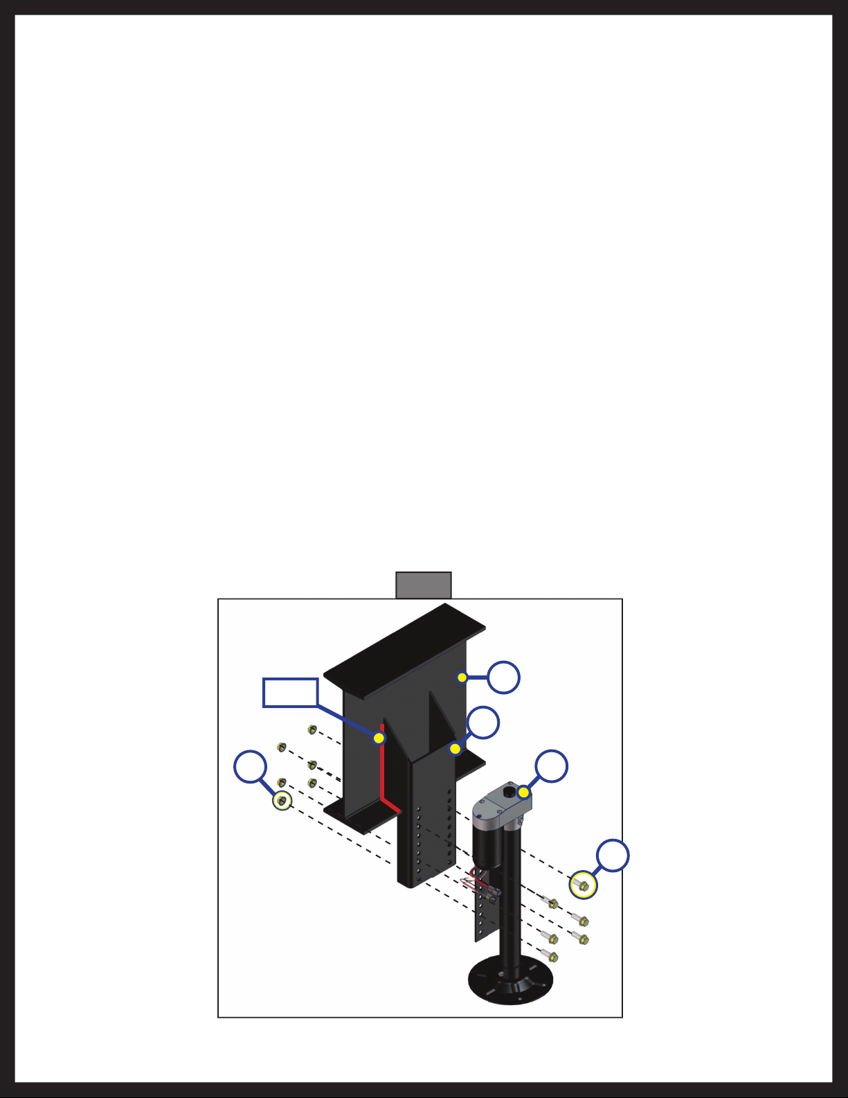
Installation - Rear Jacks
1. Determine position and ground clearance requirements for the rear jacks (Fig. 1D). The rear jack
brackets (Fig. 1C) should be mounted approximately 1 foot behind the rear axle hanger and be aligned
with each other.
NOTE: When fully retracted, rear jacks should be equal to the departure angle or a minimum of 7" of ground
clearance.
2. Mark jack mounting bracket (Fig. 1C) locations on the main frame rail.
3. Clamp the bracket to the main frame rail (Fig. 1B) in the marked position.
4. Weld the bracket to the main frame rail (Fig. 1B).
5. Bolt the rear jacks (Fig. 1D) to the mounting brackets (Fig. 1C) using six bolts (Fig. 1E) and nuts (Fig. 1A)
per jack. Tighten the bolts to 90 lb.-ft. of torque.
6. Connect the wire harnesses to the rear jack motor wires and run the harnesses to the compartment
where the controller will be mounted.
NOTE: LCI recommends zip-tying the harnesses tight against the rear jack motors to prevent damage to the
harnesses.
Fig. 1
B
Weld
C
A
D
E
Rev: 01.30.2015 Page 3
Ground Control 3.0 OEM Installation Manual
Page 4
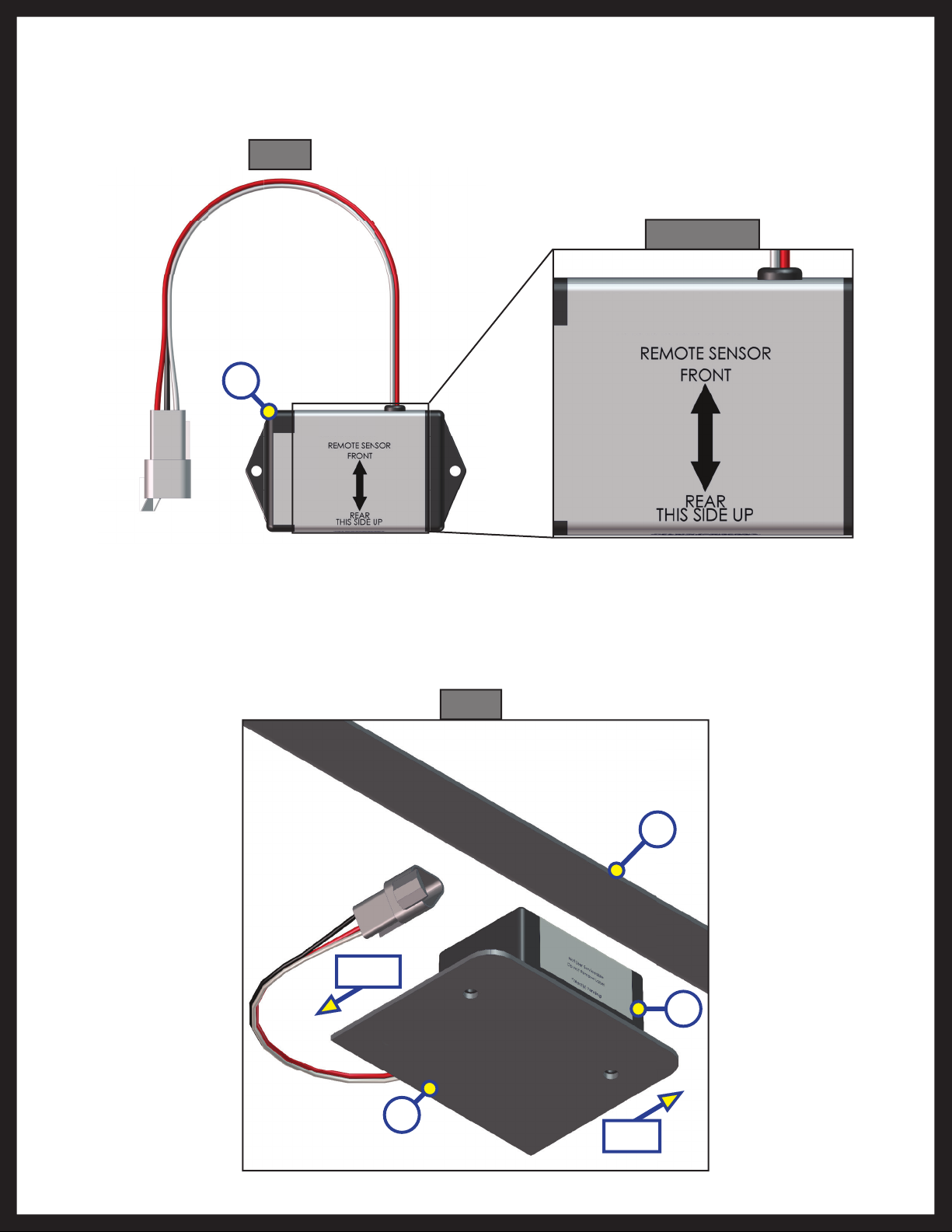
Installation - Rear Sensor
The rear sensor (Fig. 2A) MUST be installed on the crossmember to the rear of the back axle, centered curbside to
roadside on the unit with the arrows on the top of the sensor pointing the correct direction (Fig. 2 detail).
Fig. 2
Fig. 2 Detail
A
1. Dry fit the mounting plate (Fig. 3A) and the rear sensor (Fig. 3B) to the crossmember (Fig. 3C). The pre-
drilled holes in the plate are for mounting the rear sensor to the plate. Mark on the plate where the rear
sensor will set. Space between the sensor and the crossmember MUST be left so the wire harness will
not be pinched.
Fig. 3
C
Front
B
A
Rev: 01.30.2015 Page 4
Rear
Ground Control 3.0 OEM Installation Manual
Page 5
2. Attach the rear sensor (Fig. 4B) to the mounting plate (Fig. 4C) using two ⁄" hex head self-tapping
screws (Fig. 4A). Orientation is imperative for the correct operation of the leveling system.
Fig. 4
B
C
A
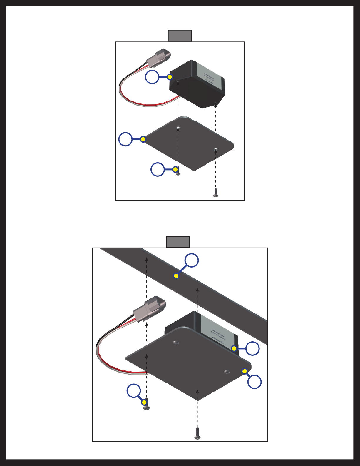
3. Attach the mounting plate (Fig. 5B) and sensor (Fig. 5C) assembly to the crossmember (Fig. 5D) using
two ⁄" hex head self-tapping screws (Fig. 5A). Ensure that the plate is centered side to side on the
frame and that the sensor is oriented properly (Fig. 5).
Fig. 5
x
D
x
C
A
Rev: 01.30.2015 Page 5
B
Ground Control 3.0 OEM Installation Manual
Page 6

4. Connect the rear sensor harness to the connector on the rear sensor (Fig. 6A )and run the harness
through the frame and up to the compartment where the controller will be mounted.
Fig. 6
A
Rev: 01.30.2015 Page 6
Ground Control 3.0 OEM Installation Manual
Page 7

Installation - Controller
NOTE: Prior to starting this portion of the installation, double check that all of the harnesses are properly
and securely connected to the rear jacks, landing gear, and rear sensor.
1. Measure the ceiling of the compartment where the controller will be placed and mark the center point
on the ceiling. The controller MUST be positioned directly in the center of the unit with the arrow on
the label of the controller facing the front of the unit (Fig. 7).
NOTE: Some 6-point controllers do not have orientation arrows for the front of the unit. When installing
those controllers, ensure that the port labeled "LEFT FRONT" is pointing to the left-hand front of the
unit. This will ensure proper orientation and function of the controller.
2. Using four #8 x 1” wood screws (Fig. 8B), attach the controller (Fig. 8A) to the ceiling of the
compartment, centered over the marked centerline of the compartment.
3. Attach the power and ground harnesses to the corresponding posts on the controller and then
connect them to the correct posts on the house battery.
4. Connect all jack harnesses to the appropriate connectors on the controller.
Fig. 7
Fig. 8
Compartment Ceiling
A
Rev: 01.30.2015 Page 7
B
Ground Control 3.0 OEM Installation Manual
Page 8

Installation - Touch Pad
1. Determine where to mount the touch pad. The touch pad should be mounted in a compartment on
the side of the unit so the operator will have a view of the hitch pin while using the touch pad.
2. Remove the faceplate of the touch pad (Fig. 9A) from the mounting bezel (Fig. 9B).
3. Cut a hole in the wall of the compartment 3 ⁄” wide by 2 ¾ ” high (Fig. 10) so the top and bottom
horizontal cuts are parallel to the floor of the compartment.
Fig. 9 Fig. 10
B
Compartment Wall
A
2 ¾ "
3 ⁄"
4. Feed the touch pad harness through this hole and run it to the compartment where the controller is
mounted. Plug the harness into the appropriate connector on the controller.
5. Insert the touch pad bezel (Fig. 11A) into the cutout and attach it with four #8x1" wood screws (Fig.
11B) with sufficient length to thread into the compartment wall.
6. Plug the touch pad harness into the connector on the back of the touch pad faceplate and snap the
faceplate into the bezel (Fig. 12).
Fig. 11
AA
B
Rev: 01.30.2015 Page 8
Fig. 12
Ground Control 3.0 OEM Installation Manual
Page 9

Wiring Diagram - 4 Point
Hall Effect Jack
Hall Effect Harness
LCD
Touch Pad
Harness
LCD Touch Pad
Rear Sensor
Rear Sensor Harness
Hall Effect Harness
4 Point Controller
OEM Supplied
Circuit
Interruption
Battery
Hall Effect Landing Gear
Rev: 01.30.2015 Page 9
Ground Control 3.0 OEM Installation Manual
Page 10

Wiring Diagram - 6 Point
Hall Effect
Landing Gear
Hall Effect
Jack
Rear Sensor
Rear Sensor
Harness
LCD Touch Pad
Touch Pad
Harness
Hall Effect Harness
Hall Effect Jack
6 Point
Controller
Battery
OEM Supplied
Circuit
Interruption
Rev: 01.30.2015 Page 10
Ground Control 3.0 OEM Installation Manual
Page 11

Touch Pad Diagram
Fig. 13
A E
B
C
D
K
G
F
H
I
J
Callout Description
A Up Arrow - Scrolls up through the menu on LCD.
B Down Arrow - Scrolls down through the menu on LCD.
C Enter - Activates modes and procedures indicated on LCD.
D
Retract - Places leveling system into retract mode. - Press and hold down for
1 second to initiate Auto Retract.
E LCD Display - Displays procedures and results.
F Auto Level - Places leveling system into auto level mode.
G Front Jack Button - Activates front jacks in manual mode.
H Left Jack Button - Activates left jacks in manual mode.
I Right Jack Button - Activates right jacks in manual mode.
J Rear Jack Button - Activates rear jacks in manual mode.
K Power Button - Turns leveling system on and off.
Rev: 01.30.2015 Page 11
Ground Control 3.0 OEM Installation Manual
Page 12

Operation
Basic Jack Operation
Landing gear jacks can be operated any time the system is “ON”. By pushing the “FRONT” button (Fig. 13G), both
front or landing gear jacks can be extended. By pushing either the "FRONT" and “LEFT” (Fig. 13H) or "FRONT" and
“RIGHT” (Fig. 13I) buttons, the individual front jacks can be extended. If the touch pad is put in the retract mode,
indicated by the orange illuminated LED next to the “RETRACT” button (Fig. 13D), the front jacks can be retracted
together by pushing the “FRONT” button (Fig. 13G) or individually by pressing “LEFT” (Fig. 13H) or “RIGHT” (Fig. 13I)
buttons, while simultaneously pressing the “FRONT” button (Fig. 13G).
NOTE: Middle jacks can only be operated in error mode. In order to engage middle jacks, press "LEFT" and
"RIGHT" buttons simultaneously.
The rear jacks can only be extended when the touch pad is in the manual mode. Once system is in manual mode,
pressing the “REAR” button (Fig. 13J) will extend both rear jacks at the same time. To extend individual rear jacks,
press the “LEFT” (Fig. 13H) or “RIGHT” (Fig. 13I) buttons while simultaneously pressing the “REAR” button (Fig. 13J),
depending on which jack needs to be operated. If the touch pad is put in the retract mode, indicated by the orange
illuminated LED next to the “RETRACT” button (Fig. 13D), the rear jacks can be retracted together by pushing the
“REAR” button (Fig. 13J) or individually by pressing either the “LEFT” (Fig. 13H) or “RIGHT” (Fig. 13I) buttons, while
simultaneously pressing the “REAR” button (Fig. 13J).
NOTE: If the rear jacks will not operate individually using the method described above, but they operate
properly when Auto Level is performed, the Twist Prevention Protection system has locked out the
operation to prevent damage to the frame of the unit.
Homing Jacks
1. Introduce an error - disconnect one of the hall effect sensor wires at the controller.
2. Attempt to operate the jack that is associated with the sensor wire that was disconnected. The touch
pad screen will display an error for that jack.
3. Reconnect the hall effect sensor wire. Manually extend all jacks down a minimum of 6 inches.
4. Press and hold the retract button until all of the jacks begin to retract. The jacks will retract until they
reach the hard current limit.
5. The jacks are now “homed.”
NOTE: If the jacks do not retract, an error should display on the touch pad screen. This is typically caused by
wiring interruption.
NOTE: In order to "home" jacks, middle jacks MUST also be extended. Refer to Basic Jack Operation for
middle jack operation.
Rev: 01.30.2015 Page 12
Ground Control 3.0 OEM Installation Manual
Page 13

Zero Point Calibration
The “Zero Point” is the programmed point that the unit will return to each time the Auto Level feature is used. The
“Zero Point” MUST be programmed prior to using the Auto Level feature to ensure the proper operation of the
system.
NOTE: Prior to starting this procedure, double check all connections on the controller, jacks, and touch pad.
1. Manually run the jacks to level the unit. This is best achieved by placing a level in the center of the unit
and leveling it both front to back and then side to side. (See “Basic Jack Operation” for instructions on
how to manually operate the system).
2. Once the unit is level, turn off the touch pad.
3. With the touch pad off, press and release the “FRONT” button (Fig. 13G) five (5) times and then press
and release the “REAR” button (Fig. 13J) five (5) times.
4. The touch pad will flash and beep and the display will read “ZERO POINT CALIBRATION ENTER to set,
Power to Exit” (Fig. 14).
5. To set the current position as the zero point, press the “ENTER” button (Fig. 13C).
6. LCD display will read “Zero Point stability check” (Fig. 15).
7. LCD display will read “Zero point set successfully” once process is complete (Fig. 16).
8. The system will set this point as its level state and the touch pad will turn off.
Fig. 14
Fig. 15
Fig. 16
Special Jack Error Codes
To clear one of these errors:
1. Correct or otherwise repair the issue (see the table below).
2. Extend all of the jacks at least six (6) inches, then press and hold the “RETRACT” button on the touch
pad until the jacks begin retracting.
3. All of the jacks will retract fully to clear the error.
LCD Message What's Happening? What Should Be Done?
***ERROR***
LF Jack
RF Jack
LM Jack
RM Jack
LR Jack
RR Jack
Rev: 01.30.2015 Page 13
Error at a specific jack (left front,
right front, left rear, right rear).
Hall signal issue (open, short,
malfunction).
Unexpected high amp current
stall.
Check harness connections
at controller and at jack.
Check harness for damage.
Repair or replace as necessary.
Ground Control 3.0 OEM Installation Manual
Page 14

Touch Pad Error Codes
NOTE: To clear an error from the touch pad, repair or otherwise correct the issue, then press “ENTER.” If the
error is still present, the message will be displayed again.
LCD Message What's Happening? What Should Be Done?
****ERROR****
Excess Angle
****ERROR****
Excessive Angle
****ERROR****
Feature Disabled
****ERROR****
Low Voltage
****ERROR****
Out Of Stroke
Controller not properly secured. Check and secure controller placement.
Excessive angle reached during
auto operation.
Relocate the coach.
Controller not properly secured. Check and secure controller placement.
Excessive angle reached during
auto operation.
Relocate the coach.
Front of coach below level when
starting Auto Level process (only
when trying to initiate Hitch
Raise front of coach above level and
restart Auto Level process.
Recognition).
Touch pad power not cycled
between consecutive leveling
operations.
Turn touch pad off and then back on to
reset the system.
Zero point not set. Set zero point.
Check wiring for loose connections.
Battery voltage dropped below
10.8V.
Test battery voltage under load - charge or
replace.
Jack has reached maximum
stroke length and is unable to lift.
Check disposition of jacks. Relocate the
coach.
****ERROR****
External Sensor
****ERROR****
Jack Time Out
****ERROR****
Auto Level Fail
****ERROR****
Bad Calibration
****ERROR****
Internal Sensor
**PANIC STOP**
Function Aborted
Bad connection or wiring from
the controller to the rear sensor.
Time limit exceeded for the
requested auto operation.
Unable to auto level due to
uneven ground.
Unable to auto level due to zero
point being set incorrectly.
Sensor calibration values are out
of range.
Replace or repair connection to rear
remote sensor.
Check disposition of jacks.
Check disposition of jacks. Relocate the
coach.
Reset zero point.
Reset zero point.
Internal sensor problem. Replace controller.
The user pressed a button on the
touch pad during an automatic
operation.
Restart automatic operation and then
refrain from pressing any buttons on the
touch pad.
Rev: 01.30.2015 Page 14
Ground Control 3.0 OEM Installation Manual
Page 15

The contents of this manual are proprietary and copyright protected by Lippert Components, Inc. (“LCI”).
LCI prohibits the copying or dissemination of portions of this manual unless prior written consent from an
authorized LCI representative has been provided. Any unauthorized use shall void any applicable warranty.
The information contained in this manual is subject to change without notice and at the sole discretion of LCI.
Revised editions are available for free download from www.lci1.com.
Please recycle all obsolete materials.
For all concerns or questions, please contact
Lippert Components, Inc.
Ph: (574) 537-8900 | Web: www.lci1.com | Email: warranty@lci1.com
Rev: 01.30.2015
Page 15
Ground Control 3.0 OEM Installation Manual
 Loading...