

Page 1

Rev: 01.30.2015
Page 1
Ground Control 3.0 Service Manual
Page 2

TABLE OF CONTENTS
System and Safety Information 2
Prior to Operation 3
Touch Pad Diagram 3
Operation 4
Basic Jack Operation 4
Unhitching from a Tow Vehicle 4
Auto Level 5
Auto Level Sequence 5
Hitch Recognition 5
Homing Jacks 6
Zero Point Calibration 6
Manual Override - Top of Jack Motor 7
Manual Override - Bottom of Jack Motor 8
Preventive Maintenance 9
Troubleshooting - Touch Pad 9
Special Jack Error Codes 9
Touch Pad Error Codes 9
Component Replacement 11
Landing Gear Replacement 11
Rear Jack Replacement 12
Rear Sensor Replacement 12
Controller Replacement 17
Touch Pad Replacement 18
Jack Motor Replacement 18
4 - Point Wiring Diagram 19
6 - Point Wiring Diagram 20
Ground Control 3.0 OEM Assembly 21
Ground Control 3.0 Components 22 - 25
System and Safety Information
Failure to act in accordance with the following may result in death or serious personal injury. The use of
the Ground Control 3.0 leveling system to support the unit for any reason other than which it is intended
is prohibited by Lippert’s limited warranty. The Lippert leveling system is designed as a “leveling”
system only and should not be used to provide service for any reason under the coach such as changing
tires or servicing the leveling system. Any attempts to change tires or perform other service while unit
is supported by the Ground Control 3.0 leveling system could result in damage to the 5th wheel and/or
cause death or serious injury.
Be sure to park the unit on solid, level ground. Clear all jack landing locations of debris and obstructions.
Locations should also be free of depressions. When parking the unit on extremely soft surfaces, utilize
load distribution pads under each jack. People and pets should be clear of coach while operating leveling
system. Never lift the unit completely off the ground. Lifting the unit so the wheels are not touching the
ground will create an unstable and unsafe condition.
Rev: 01.30.2015
Page 2
Ground Control 3.0 Service Manual
Page 3
Prior to Operation
The leveling system should only be operated under the following conditions:
1. The unit is parked on a reasonably level surface.
2. Be sure all persons, pets, and property are clear of the coach while the leveling system is in operation.
3. Make sure battery(ies) are fully charged and test at 12+VDC under load.
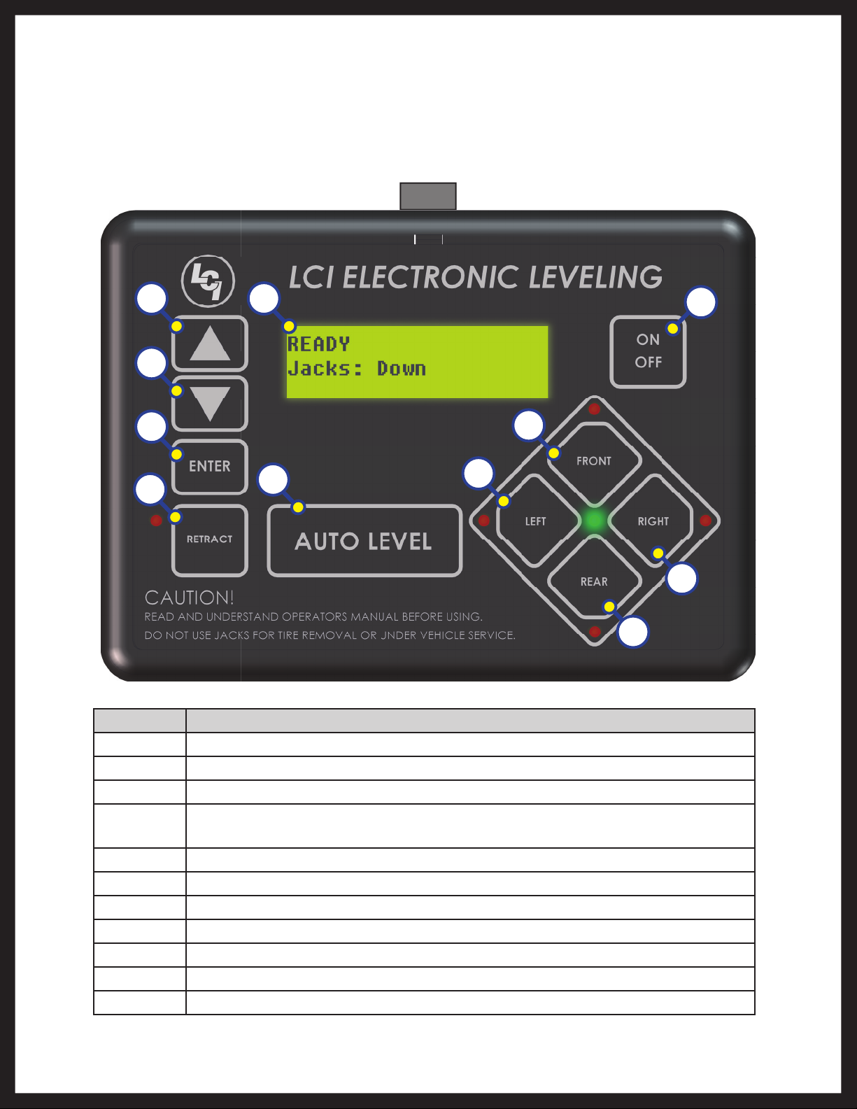
Touch Pad Diagram
Fig. 1
A E
B
C
D
K
G
F
H
I
J
Rev: 01.30.2015
Callout Description
A Up Arrow - Scrolls up through the menu on LCD.
B Down Arrow - Scrolls down through the menu on LCD.
C Enter - Activates modes and procedures indicated on LCD.
D
Retract - Places leveling system into retract mode. - Press and hold down for
1 second to initiate Auto Retract.
E LCD Display - Displays procedures and results.
F Auto Level - Places leveling system into auto level mode.
G Front Jack Button - Activates front jacks in manual mode.
H Left Jack Button - Activates left jacks in manual mode.
I Right Jack Button - Activates right jacks in manual mode.
J Rear Jack Button - Activates rear jacks in manual mode.
K Power Button - Turns leveling system on and off.
Page 3
Ground Control 3.0 Service Manual
Page 4
Operation
Basic Jack Operation
Landing gear jacks can be operated any time the system is “ON”. By pushing the “FRONT” button (Fig. 1G), both
front or landing gear jacks can be extended. By pushing either the "FRONT" and “LEFT” (Fig. 1H) or "FRONT" and
“RIGHT” (Fig. 1I) buttons, the individual front jacks can be extended. If the touch pad is put in the retract mode,
indicated by the orange illuminated LED next to the “RETRACT” button (Fig. 1D), the front jacks can be retracted
together by pushing the “FRONT” button (Fig. 1G) or individually by pressing “LEFT” (Fig. 1H) or “RIGHT” (Fig. 1I)
buttons, while simultaneously pressing the “FRONT” button (Fig. 1G).
NOTE: Middle jacks can only be operated in error mode. In order to engage middle jacks, press "LEFT" and
"RIGHT" buttons simultaneously.
The rear jacks can only be extended when the touch pad is in the manual mode. Once system is in manual mode,
pressing the “REAR” button (Fig. 1J) will extend both rear jacks at the same time. To extend individual rear jacks,
press the “LEFT” (Fig. 1H) or “RIGHT” (Fig. 1I) buttons while simultaneously pressing the “REAR” button (Fig. 1J),
depending on which jack needs to be operated. If the touch pad is put in the retract mode, indicated by the orange
illuminated LED next to the “RETRACT” button (Fig. 1D), the rear jacks can be retracted together by pushing the
“REAR” button (Fig. 1J) or individually by pressing either the “LEFT” (Fig. 1H) or “RIGHT” (Fig. 1I) buttons, while
simultaneously pressing the “REAR” button (Fig. 1J).
NOTE: If the rear jacks will not operate individually using the method described above, but they operate
properly when Auto Level is performed, the Twist Prevention Protection system has locked out the
operation to prevent damage to the frame of the unit.
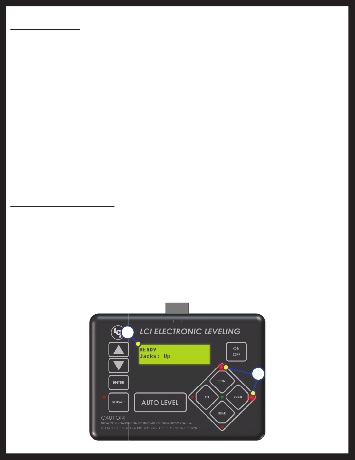
Unhitching from a Tow Vehicle
NOTE: Prior to unhitching from the tow vehicle, ensure unit is parked on a level surface and be sure to chock
the tires of the unit.
1. Extend the inner legs of both landing gear 4-5 inches by pulling on the quick release pins.
2. Push “ON/OFF” (Fig. 1K). LCD Screen will light up and display “READY JACKS: UP” (Fig. 2A).
3. Push the “UP” arrow (Fig. 1A) to scroll to “Drop Front Jacks” option on LCD screen.
4. Red indicator lights (Fig. 2B) may come on, indicating the current disposition of the unit. In this case,
the front and right sides of the unit are low.
5. Push “ENTER” (Fig. 1C). Both front landing gear jacks will go to ground and stop.
6. Push the “FRONT” button (Fig. 1G) extending the front landing gear to a sufficient height, which raises
the front of the unit off of the tow vehicle’s 5th wheel hitch plate.
7. Pull tow vehicle away and park at a safe distance.
Fig. 2
A
Rev: 01.30.2015
Page 4
B
Ground Control 3.0 Service Manual
Page 5

Auto Level
1. After unhitching from tow vehicle and parking the vehicle at a safe distance away from the unit, press
the “ON/OFF” button (Fig. 1K) and then press “AUTO LEVEL” (Fig. 1F).
NOTE: Once the automatic leveling cycle has been started, it is important that there is no movement in the
coach until the unit has completed the leveling process. Failure to remain still during the leveling
cycle could have an effect on the performance of the leveling system.
NOTE: In order for hitch recognition feature to function, the auto level sequence MUST be started with the
front of the unit above level.
Auto Level Sequence
1. When Auto Level Sequence begins, the front of the unit will lower slightly to a point below level. The
coach will then stop and raise up to the point where it is level from front to rear.
2. Rear leveling jacks are grounded.
3. A side to side leveling sequence occurs.
NOTE: At this point on the 6-point system, the two middle jacks are grounded to stabilize the unit. These
two jacks do not level the unit.
4. Each jack will perform a final grounding touch.
5. LCD will read “AUTO LEVEL SUCCESS” (Fig. 3).
6. LCD will then read “READY Jacks: Down” (Fig. 4A), and the green LED at the center of the four jack
buttons will be illuminated (Fig. 4B).
Fig. 4
A
Fig. 3
B
NOTE: If the AUTO LEVEL sequence does not perform as described, place the system in the manual mode
and test that the jacks operate correctly by pushing their coordinating buttons on the touch pad;
i.e. FRONT button operates only the front jacks.
Hitch Recognition
1. Turn on touch pad.
2. Press the left and right buttons simultaneously (Fig. 1H/I).
3. All leveling jacks will retract first, then the landing gear will extend to raise the unit to the height where
the auto level sequence was started.
NOTE: If the auto level sequence was started with the front of the unit in a below-level condition, the
Hitch Recognition will not function and the LCD will display “Feature Disabled.” In order for hitch
recognition feature to function, the auto level sequence MUST be started with the front of the unit
above level.
Rev: 01.30.2015
Page 5
Ground Control 3.0 Service Manual
Page 6
Homing Jacks
1. Introduce an error - disconnect one of the hall effect sensor wires at the controller.
2. Attempt to operate the jack that is associated with the sensor wire that was disconnected. The touch
pad screen will display an error for that jack.
3. Reconnect the hall effect sensor wire. Manually extend all jacks down a minimum of 6 inches.
4. Press and hold the retract button until all of the jacks begin to retract. The jacks will retract until they
reach the hard current limit.
5. The jacks are now “homed.”
NOTE: If the jacks do not retract, an error should display on the touch pad screen. This is typically caused by
wiring interruption.
NOTE: In order to "home" jacks, middle jacks MUST also be extended. Refer to Basic Jack Operation for
middle jack operation.
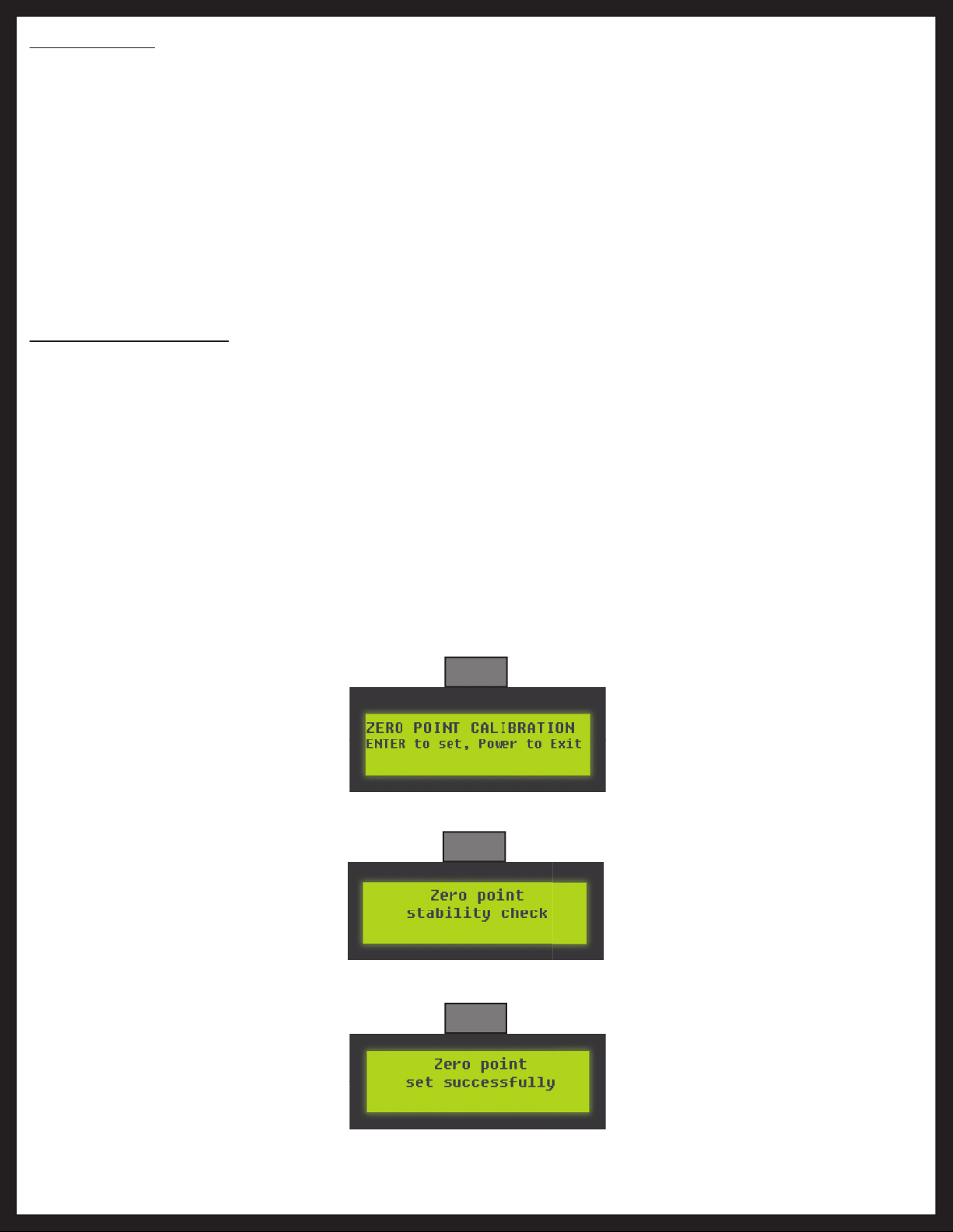
Zero Point Calibration
The “Zero Point” is the programmed point that the unit will return to each time the Auto Level feature is used. The
“Zero Point” MUST be programmed prior to using the Auto Level feature to ensure the proper operation of the
system.
NOTE: Prior to starting this procedure, double check all connections on the controller, jacks, and touch pad.
1. Manually run the jacks to level the unit. This is best achieved by placing a level in the center of the unit
and leveling it both front to back and then side to side. (See “Basic Jack Operation” for instructions on
how to manually operate the system).
2. Once the unit is level, turn off the touch pad.
3. With the touch pad off, press and release the “FRONT” button (Fig. 1G) five (5) times and then press
and release the “REAR” button (Fig. 1J) five (5) times.
4. The touch pad will flash and beep and the display will read “ZERO POINT CALIBRATION ENTER to set,
Power to Exit” (Fig. 5).
5. To set the current position as the zero point, press the “ENTER” button (Fig. 1C).
Fig. 5
6. LCD display will read “Zero Point stability check” (Fig. 6).
Fig. 6
7. LCD display will read “Zero point set successfully” once process is complete (Fig. 7).
Fig. 7
8. The system will set this point as its level state and the touch pad will turn off.
Rev: 01.30.2015
Page 6
Ground Control 3.0 Service Manual
Page 7

Manual Override - Top of Jack Motor
NOTE: Use of a 12V-18V cordless screw gun or pneumatic screw gun is acceptable to manually override the
jacks. Do not use an impact screw gun to perform the override procedure, as this may damage the
motor.
If manual override is necessary on any jack in the system, there are two options. The following process will describe
how to use the top override. See next page for the bottom override.
Tools needed: ⁄” drive ratchet and extension (no socket).
1. Find the port on the top of the jack motor (Fig. 8A).
2. Remove the rubber plug (Fig. 9).
Fig. 8
A
Fig. 9
3. Insert the ⁄” drive into the port (Fig. 10).
4. Turn override until the jack extends or retracts to desired position (Fig. 11).
Fig. 10
Rev: 01.30.2015
Page 7
Fig. 11
Ground Control 3.0 Service Manual
Page 8

Manual Override - Bottom of Jack Motor
NOTE: Use of a 12V-18V cordless screw gun or pneumatic screw gun is acceptable to manually override the
jacks. Do not use an impact screw gun to perform the override procedure, as this may damage the
motor.
If manual override is necessary on any jack in the system, there are two options. The following process will describe
how to use the bottom override. See previous page for the top override.
Tools needed: ⁄” drive ratchet and extension, ⁄” socket.
1. Find the port on the bottom of the jack motor (Fig. 12A).
2. Remove the rubber plug (Fig. 13).
Fig. 12
Fig. 13
A
3. Insert the ⁄” socket into the port (Fig. 14).
4. Turn override until the jack extends or retracts to desired position (Fig. 15).
Fig. 14 Fig. 15
Rev: 01.30.2015
Page 8
Ground Control 3.0 Service Manual
Page 9
Preventive Maintenance
1. Remove dirt and road debris from jacks and stabilizer struts (if equipped) as needed.
2. If jacks are down for extended periods, it is recommended to spray exposed leveling jack tubes with
a spray lubricant every 3 months for protection. If the coach is located in a salty environment, it is
recommended to spray the rods every month.
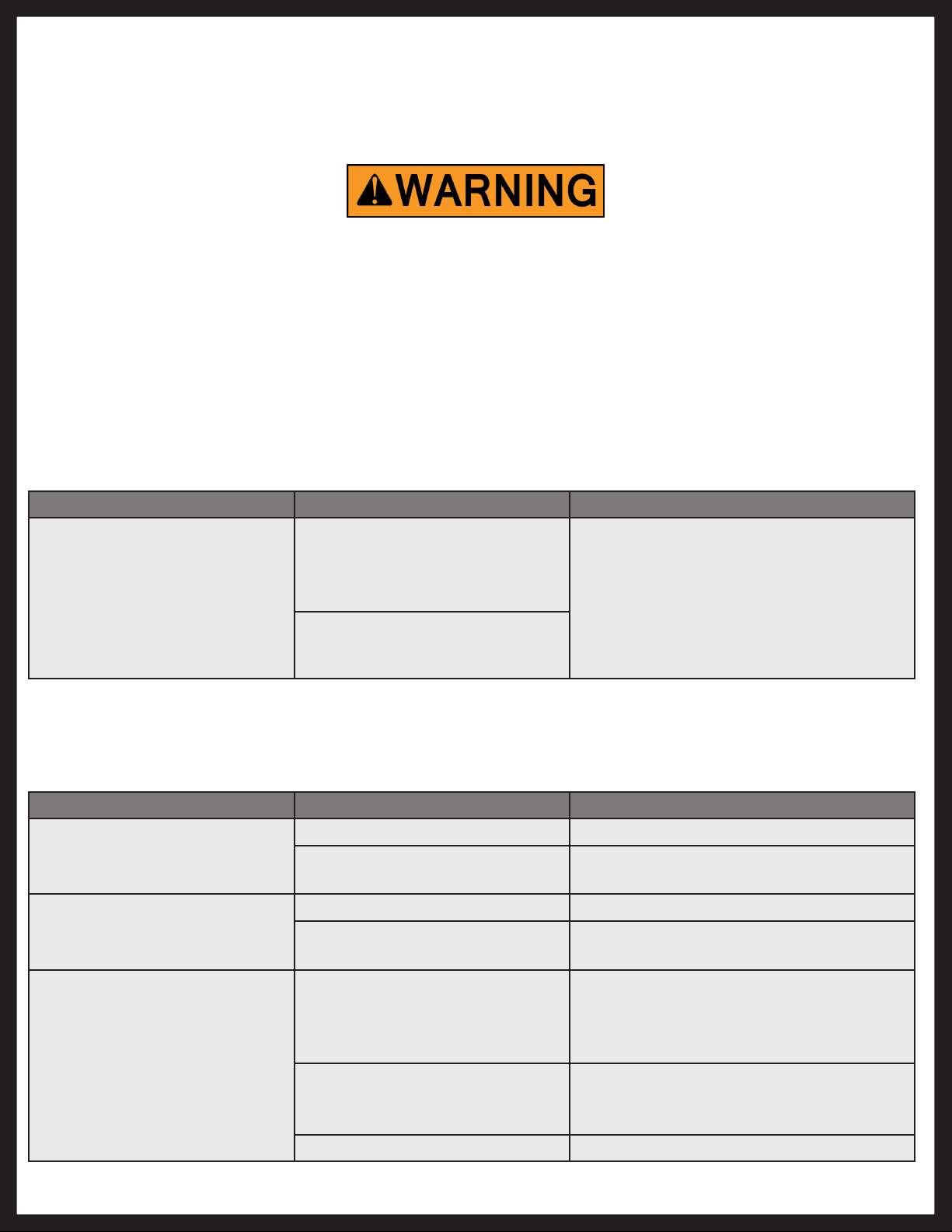
Ensure the coach is supported at both the front and rear with jack stands before performing any
troubleshooting or service to the unit. Failure to do so may result in death or personal injury.
Troubleshooting - Touch Pad
Special Jack Error Codes
To clear one of these errors:
1. Correct or otherwise repair the issue (see the table below).
NOTE: Extend all of the jacks at least six (6) inches, then press and hold the “RETRACT” button on the
touch pad until the jacks begin retracting. Refer to Basic Jack Operation for middle jack extension
procedure.
2. All of the jacks will retract fully to clear the error.
LCD Message What's Happening? What Should Be Done?
***ERROR***
LF Jack
RF Jack
LM Jack
RM Jack
LR Jack
RR Jack
Error at a specific jack (left front,
right front, left rear, right rear).
Hall signal issue (open, short,
malfunction).
Unexpected high amp current
stall.
Check harness
connections at controller and at jack.
Check harness for damage.
Repair or replace as necessary.
Touch Pad Error Codes
NOTE: To clear an error from the touch pad, repair or otherwise correct the issue, then press “ENTER”. If the
error is still present, the message will be displayed again.
LCD Message What's Happening? What Should Be Done?
****ERROR****
Excess Angle
****ERROR****
Excessive Angle
Controller not properly secured. Check and secure controller placement.
Excessive angle reached during
auto operation.
Controller not properly secured. Check and secure controller placement.
Excessive angle reached during
auto operation.
Relocate the coach.
Relocate the coach.
Rev: 01.30.2015
****ERROR****
Feature Disabled
Front of coach below level when
starting Auto Level process (only
when trying to initiate Hitch
Recognition).
Touch pad power not cycled
between consecutive leveling
operations.
Zero point not set. Set zero point.
Page 9
Raise front of coach above level and
restart Auto Level process
Turn touch pad off and then back on to
reset the system.
Ground Control 3.0 Service Manual
Page 10

LCD Message What's Happening? What Should Be Done?
****ERROR****
Low Voltage
****ERROR****
Out Of Stroke
****ERROR****
External Sensor
****ERROR****
Jack Time Out
****ERROR****
Auto Level Fail
****ERROR****
Bad Calibration
****ERROR****
Internal Sensor
**PANIC STOP**
Function Aborted
Battery voltage dropped below
Check wiring for loose connection.
10.8V.
Test battery voltage under load - charge or
replace.
Jack has reached maximum
stroke length and is unable to lift.
Bad connection or wiring from
the controller to the rear sensor.
Time limit exceeded for the
requested auto operation.
Unable to auto level due to
uneven ground.
Unable to auto level due to zero
point being set incorrectly.
Sensor calibration values are out
of range.
Check disposition of jacks. Relocate the
coach.
Replace or repair connection to rear
remote sensor.
Check disposition of jacks.
Check disposition of jacks. Relocate the
coach.
Reset zero point.
Reset zero point.
Internal sensor problem. Replace controller.
The user pressed a button on the
touch pad during an automatic
operation.
Restart automatic operation and then
refrain from pressing any buttons on the
touch pad.
Rev: 01.30.2015
Page 10
Ground Control 3.0 Service Manual
Page 11

Component Replacement
NOTE: After replacing any of these components, you will need to "home" the jacks. See the corresponding
sections for instructions.
Landing Gear Replacement
1. Remove existing landing gear from the unit by removing the carriage bolts and nuts in the brackets
that are holding the landing gear in place.
2. Using the new carriage bolts and nuts, mount the new landing gear in the brackets so that the tabs
on the new landing gear are positioned between the mounting brackets as shown in Figs. 16 and 17.
Tighten the nuts on the carriage bolts until the bracket opening is less than 2 ½ ”.
3. Connect the wire harnesses to the landing gear motor wires and run the harnesses to the
compartment where the controller will be mounted.
NOTE: LCI recommends zip-tying the harnesses tight against the landing gear motors to prevent damage to
the harnesses.
Fig. 16 Fig. 17
Main Frame Rail
Tab
Landing Gear
Tab
Rev: 01.30.2015
Page 11
Ground Control 3.0 Service Manual
Page 12

Rear Jack Replacement
1. Unbolt the jack from mounting bracket.
2. Bolt the new rear jack (Fig. 18C) to the mounting bracket (Fig. 18B) using six bolts (Fig. 18D) and nuts
(Fig. 18A) per jack. Tighten the bolts to 90 lb.-ft. of torque.
3. Connect the wire harnesses to the rear jack motor wires.
NOTE: LCI recommends zip-tying the harnesses tight against the rear jack motors to prevent damage to the
harnesses.
Fig. 18
Main Frame Rail
B
A
C
D
Rear S ensor Replacement
1. Locate the rear sensor in the underbelly of the coach.
2. Cut an access panel in the underbelly using a knife. The rear sensor should be installed on the
crossmember to the rear of the back axle, centered curbside to roadside on the unit.
Rev: 01.30.2015
Be sure not to cut any hoses or wires that may be under the underbelly.
Page 12
Ground Control 3.0 Service Manual
Page 13

3. Disconnect the rear sensor harness from the connector on the rear sensor (Fig. 19A).
Fig. 19
A
4. Remove the screws (Fig. 20A), mounting plate (Fig. 20B) and sensor (Fig. 20C) assembly from the
crossmember (Fig. 20D).
Fig. 20
B
D
C
Rev: 01.30.2015
A
Page 13
Ground Control 3.0 Service Manual
Page 14

5. Remove the screws (Fig. 21A) from the rear sensor (Fig. 21B) and mounting plate (Fig. 21C) and remove
the sensor from the plate.
Fig. 21
B
C
A
6. Dry fit the mounting plate (Fig. 22A) and the replacement rear sensor (Fig. 22B) to the crossmember
(Fig. 22C). The pre-drilled holes in the plate are for mounting the rear sensor to the plate. Mark on the
plate where the rear sensor will set. Space between the sensor and the crossmember MUST be left so
the wire harness will not be pinched.
Fig. 22
C
Front
Rev: 01.30.2015
B
A
Page 14
Rear
Ground Control 3.0 Service Manual
Page 15

7. Attach the replacement rear sensor (Fig. 23B) to the mounting plate (Fig. 23C) using two ⁄" hex head
self tapping screws (Fig. 23A). Orientation is imperative for the correct operation of the leveling system.
Fig. 23
B
C
A
8. Attach the mounting plate (Fig. 24B) and replacement sensor (Fig. 24C) assembly to the crossmember
(Fig. 24D) using two ⁄" hex head self tapping screws (Fig. 24A). Ensure that the plate is centered side
to side on the frame and that the sensor is oriented properly (Fig. 24).
Fig. 24
x
D
x
C
B
Rev: 01.30.2015
A
Page 15
Ground Control 3.0 Service Manual
Page 16
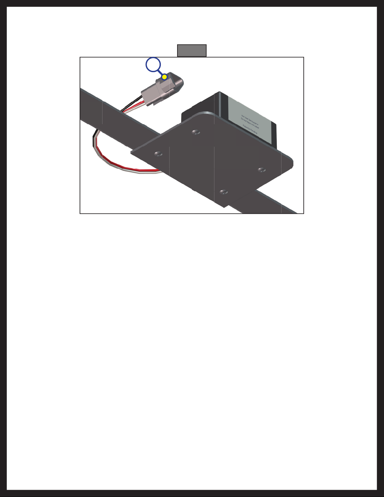
9. Connect the rear sensor harness to the connector on the rear sensor (Fig. 25A) and run the harness
through the frame and up to the compartment where the controller will be mounted.
Fig. 25
A
Rev: 01.30.2015
Page 16
Ground Control 3.0 Service Manual
Page 17

Controller Replacement
1. Disconnect all jack harnesses from the connectors on the controller.
2. Remove the power and ground harness from the controller.
3. Remove the controller (Fig. 26A) from the ceiling of the compartment.
4. Using four #8 x 1” wood screws (Fig. 26B), attach the replacement controller (Fig. 26A) to the ceiling of
the compartment, in the same position as the removed controller.
NOTE: The controller should be positioned directly in the center of the unit with the arrow on the label of
the controller facing the front of the coach (Fig. 27).
NOTE: Some 6-point controllers do not have orientation arrows for the front of the unit. When installing
those controllers, ensure that the port labeled "LEFT FRONT" is pointing to the left-hand front of
the unit. This will ensure proper orientation and function of the controller. Attach the power and
ground harness to the corresponding posts on the replacement controller and then connect them
to the correct posts on the house battery.
5. Connect all jack harnesses to the appropriate connectors on the replacement controller.
Fig. 26
Compartment Ceiling
A
Fig. 27
Rev: 01.30.2015
B
Page 17
Ground Control 3.0 Service Manual
Page 18

Touch Pad Replacement
1. Remove the face plate of the touch pad (Fig. 28A) from the mounting bezel (Fig. 28B).
2. Unplug the harness from the connector on the back of the face plate.
3. Plug the touch pad harness into the connector on the back of the replacement touch pad face plate
and snap the face plate into the bezel.
Fig. 28
B
A
Jack Motor Replacement
1. Using a ½ " socket or wrench, remove the two motor retention bolts from the jack (Fig. 29).
2. Remove the faulty motor from the top of the jack (Fig. 30).
3. Gently position the replacement motor into the coupler found inside the jack.
4. Replace and tighten motor retention bolts.
Fig. 29
Fig. 30
Rev: 01.30.2015
Page 18
Ground Control 3.0 Service Manual
Page 19
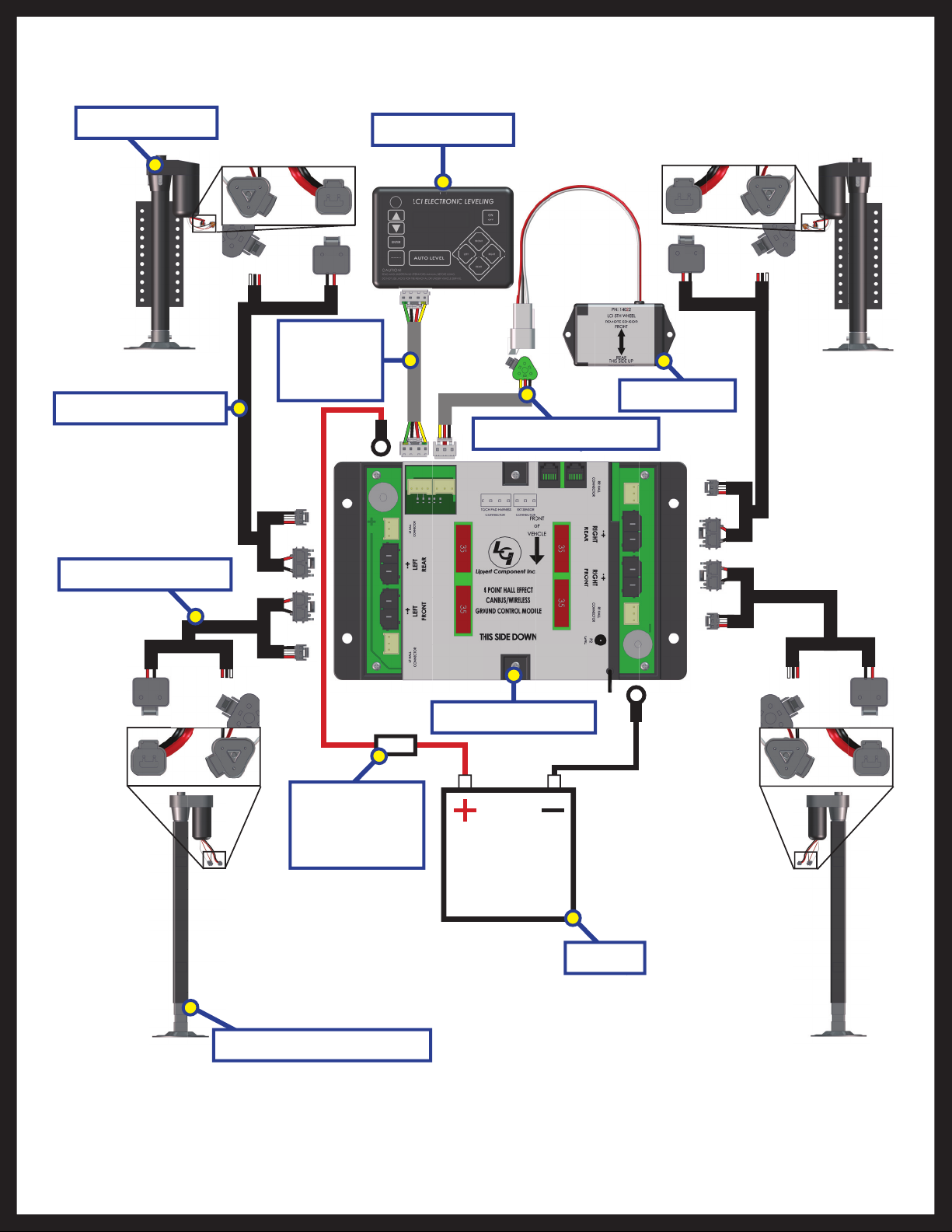
4 - Point Wiring Diagram
Hall Effect Jack
Hall Effect Harness
LCD
Touch Pad
Harness
LCD Touch Pad
Rear Sensor
Rear Sensor Harness
Hall Effect Harness
4 Point Controller
OEM Supplied
Circuit
Interruption
Battery
Rev: 01.30.2015
Hall Effect Landing Gear
Page 19
Ground Control 3.0 Service Manual
Page 20
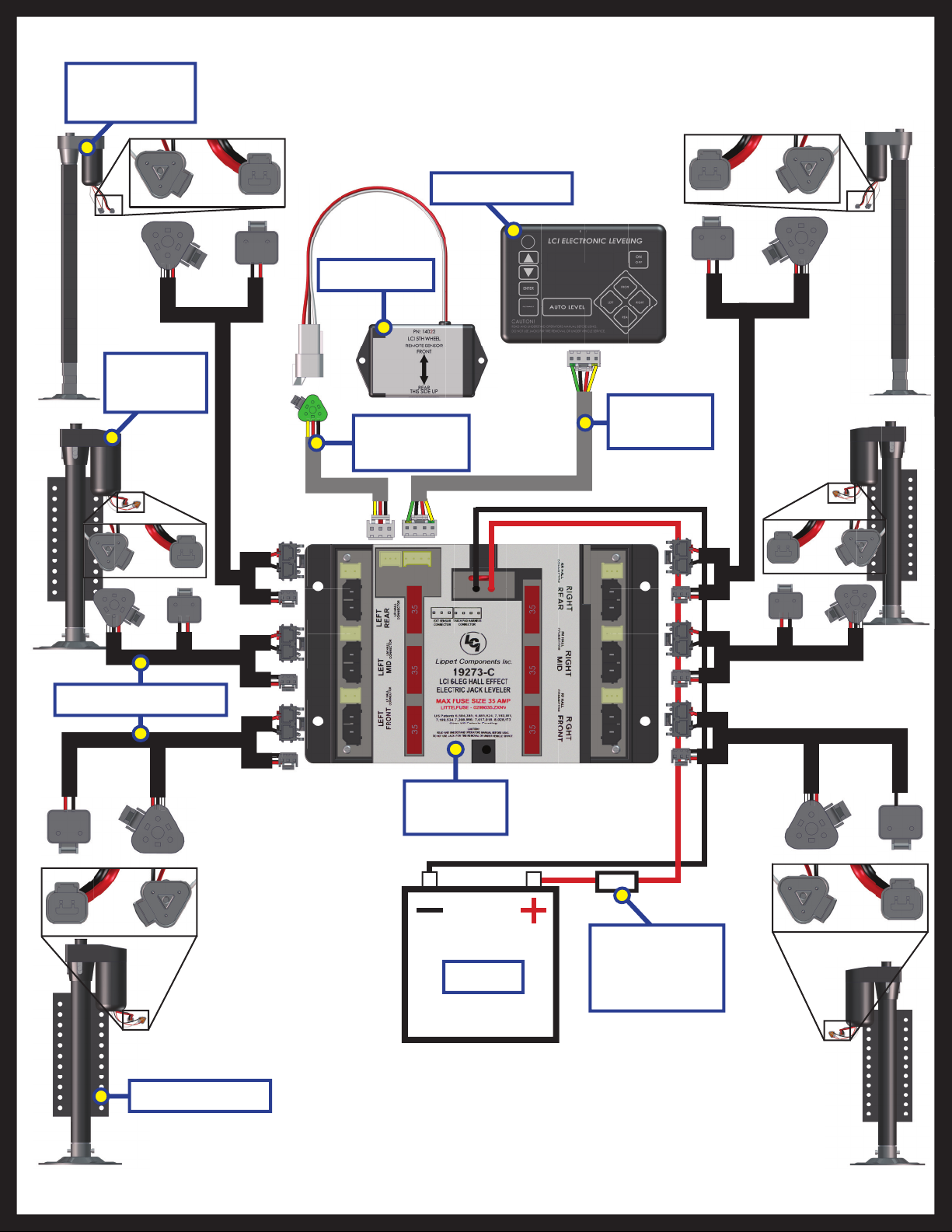
6 - Point Wiring Diagram
Hall Effect
Landing Gear
Hall Effect
Jack
Rear Sensor
Rear Sensor
Harness
LCD Touch Pad
Touch Pad
Harness
Hall Effect Harness
Hall Effect Jack
6 Point
Controller
Battery
OEM Supplied
Circuit
Interruption
Rev: 01.30.2015
Page 20
Ground Control 3.0 Service Manual
Page 21
Hall Effect
Jack; Rear Left
GROUND CONTROL 3.0 OEM ASSEMBLY
LEVELING AND STABILIZATION
Jack Mounting Nut
Bolt On
Pull Pin
Landing
Gear
Rear Sensor
Mounting
Screw
Jack Mounting Bolt
Snapper Pin
Hall Effect
Jack; Rear
Right
Landing
Gear Harness
Power and
Ground
Harness
Jack Mounting
Bracket
Carriage Bolt
Top Lock Nut
Controller
LCD Touch Pad
Rear Sensor
Rear Sensor
Rear Jack
Harness
Contact us: Lippert Components Inc. - www.lci1.com/customerservice - Phone: (574) 537-8900 - Email: warranty@lci1.com
Mounting Plate
Rear Sensor
Harness
Pad Harness
LCD Touch
Page 22
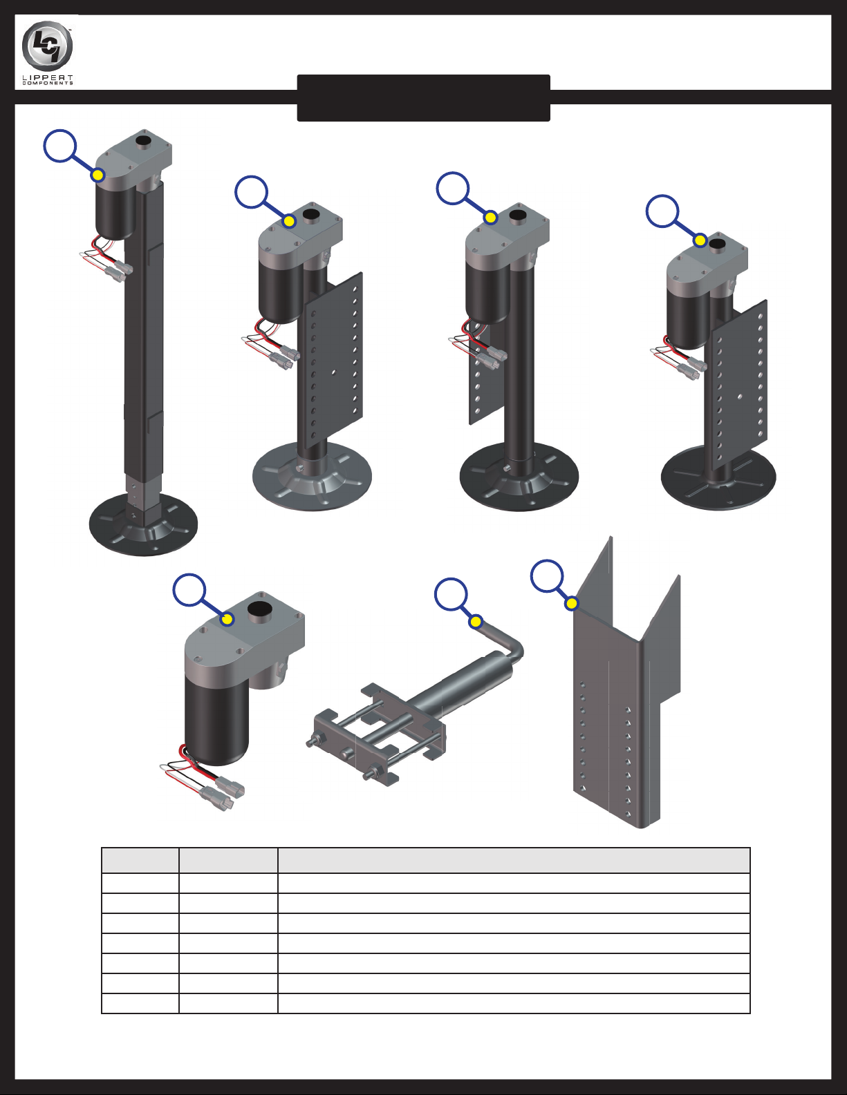
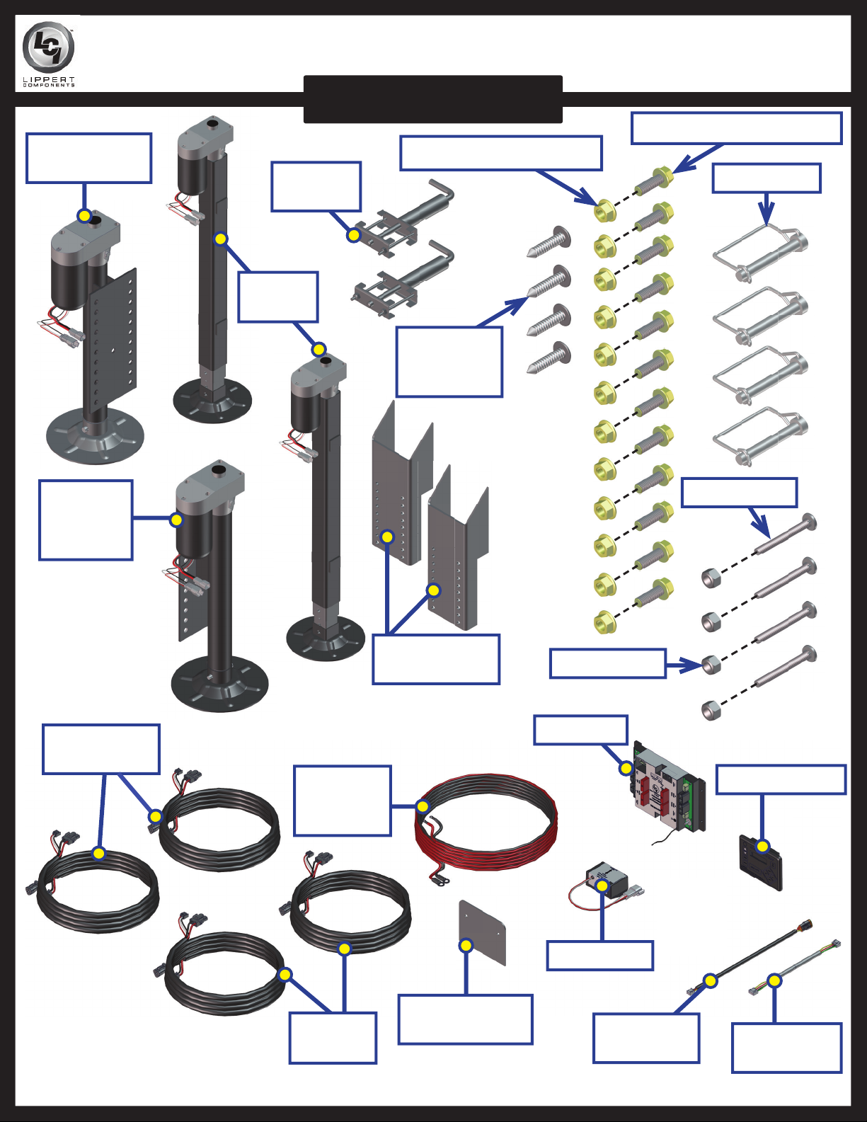
GROUND CONTROL 3.0 COMPONENTS
LEVELING AND STABILIZATION
A
B
E
C
D
G
F
Callout Part # Description
A 305340 Hall Effect Landing Gear; Front Stroke 19.8125"
B 305339 Hall Effect Jack; Rear Left 12.5" Stroke
C 344792 Hall Effect Jack; Rear Right 12.5" Stroke
D 342610 Hall Effect Jack; Rear Short 10.5" Stroke
E 343758 Hall Effect Jack Motor
F 119113 Bolt On Pull Pin
G 134989 Weld On Jack Mounting Bracket (OEM Only)
Contact us: Lippert Components Inc. - www.lci1.com/customerservice - Phone: (574) 537-8900 - Email: warranty@lci1.com
Page 23
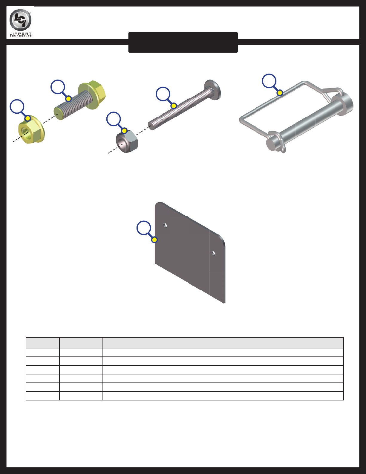
GROUND CONTROL 3.0 COMPONENTS
LEVELING AND STABILIZATION
H
I
L
K
J
M
Callout Part # Description
H 178210 Jack Mounting Nut; ½ " - 20
I 118076 Jack Mounting Bolt; ½ " - 20 x 1 ½ " Flange
J 119073 Top Lock Nut
K 125878 Carriage Bolt
L 225598 Snapper Pin; ⁄ x 3"
M 231775 Rear Sensor Mounting Plate
Contact us: Lippert Components Inc. - www.lci1.com/customerservice - Phone: (574) 537-8900 - Email: warranty@lci1.com
Page 24
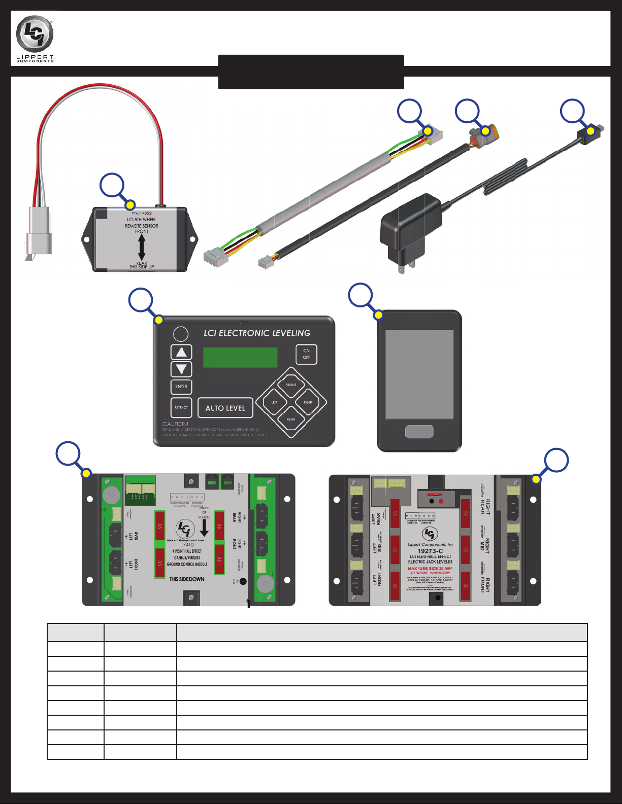
GROUND CONTROL 3.0 COMPONENTS
LEVELING AND STABILIZATION
N
O P
R
S
Q
T
Callout Part # Description
N 232201 Rear Sensor
O 232937 LCD Touch Pad Harness
P 243688 Rear Sensor Harness
Q 267401 Linc Remote Charger
R 234802 LCD Touch Pad
S 329164 Linc Remote
T 304136 4-Point Hall Effect Canbus Wireless Ground Control Controller
U 346005 6-Point Hall Effect Ground Control Controller
U
Contact us: Lippert Components Inc. - www.lci1.com/customerservice - Phone: (574) 537-8900 - Email: warranty@lci1.com
Page 25
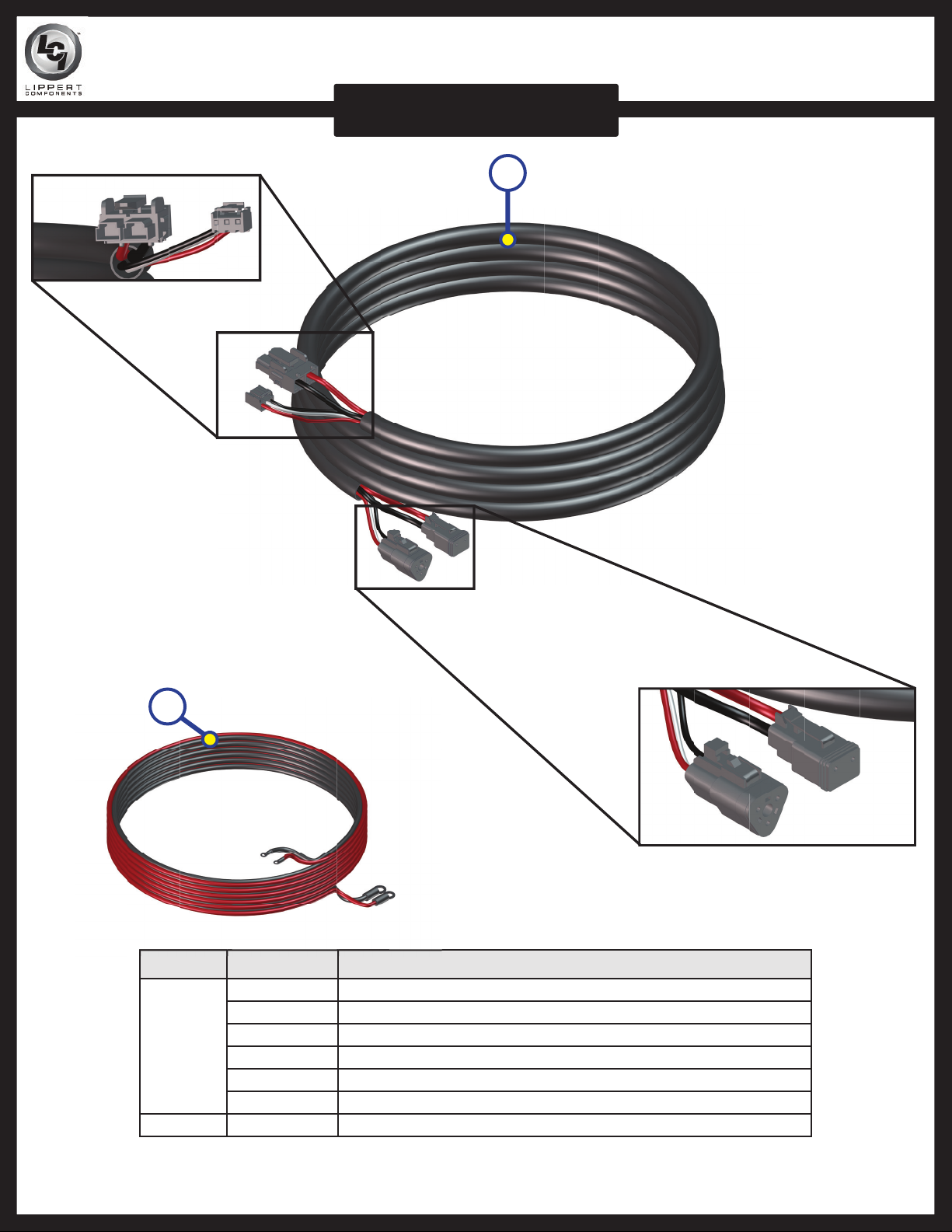
GROUND CONTROL 3.0 COMPONENTS
LEVELING AND STABILIZATION
V
W
Callout Part # Description
305115 Hall Effect Right Rear Sensor Harness
306298 Hall Effect Left Rear Sensor Harness
V
W 306176 Power and Ground Supply Harness
307489 Hall Effect Right Front Sensor Harness
307490 Hall Effect Left Front Sensor Harness
347012 Hall Effect Right Mid Harness
347013 Hall Effect Left Mid Harness
Contact us: Lippert Components Inc. - www.lci1.com/customerservice - Phone: (574) 537-8900 - Email: warranty@lci1.com
Page 26

The contents of this manual are proprietary and copyright protected by Lippert Components, Inc. (“LCI”).
LCI prohibits the copying or dissemination of portions of this manual unless prior written consent from an
authorized LCI representative has been provided. Any unauthorized use shall void any applicable warranty.
The information contained in this manual is subject to change without notice and at the sole discretion of LCI.
Revised editions are available for free download from www.lci1.com.
Please recycle all obsolete materials.
For all concerns or questions, please contact
Lippert Components, Inc.
Ph: (574) 537-8900 | Web: www.lci1.com | Email: warranty@lci1.com
Rev: 01.30.2015
Page 26
Ground Control 3.0 Service Manual
 Loading...