

Page 1

REAR ANCHOR INSTALLATION
Rear anchors are installed in the end of the bumper. There is no precise mounting location
since a variety of bumpers may be installed.
4
Frame Mount
1
Camper Tiedown System
IMPORTANT NOTE: If the stock GM bumper is installed on this truck,
The FM-CBB07 bumper brace kit MUST BE INSTALLED.
Installation is simple, requires no drilling and takes about 5 minutes.
Instructions are included with the bumper brake kit.
1. Mounting location should be as flat & vertical as possible.
2. Be sure no moldings or bumper caps interfere with the removable coupler.
3. Check back side of selected mounting location to ensure adequate
access for tightening nut.
4. Choose a location as far back as possible from the front edge of bumper
while giving consideration to the other criteria listed above and center
punch and drill a
Install Anchor Bolt with 2” fender washer, lock washer & nut.
1
/8” pilot hole, then enlarge to 1/2”.
Flat edges of Anchor Bolt must be horizontal.
Remove
coupler
when not
in use to
prevent loss.
Flats Horizontal
Place well back
From front edge
Of bumper
WARRANTY INFORMATION
All products manufactured by Happijac Co. are warranted to the retail customer for one year from date of purchase
against defects in material or workmanship. Any defective part(s) will be repaired or replaced (at Happijac’s op tion)
without charge, when returned transportation prepaid.
There are no other expressed warranties except as set forth above and any implied warranties are limited in duration to
that of the expressed warranty. This warranty does not cover any damage due to misuse, negligence, or accidents. There
is no warranty covering consequential damages, incidental damages, or incidental expenses including damage to
property.
This warranty gives you specific legal rights. You may have other rights which may vary from state to state.
All defective material must be returned to the factory via prepaid shipment. Upon inspection and determination of claims
warranted, the factory will repair/replace the material at no charge and return the repa ired/replaced material to the
customer with delivery charges prepaid by Happijac via common carrier of Happijac's choosing. Upgrades and changes
to shipping mode resulting in additional shipping costs shall be at customers expense.
TERMS OF THE WARRANTY:
WARRANTY CLAIMS:
Models: FT-CG07 & FT-CG07S
ALSO REQUIRED: USB-010 Stabilizer Bar & FM-CBB07 Bumper Brace
IMPORTANT: READ THESE INSTRUCTIONS COMPLETELY BEFORE BEGINNING:
These Instructions will show installation of one side only. Both sides install the same except where noted otherwise.
CAUTION
WARNING (New body style ) tr uck m odel, the FT-CG07S CANNOT be installed on
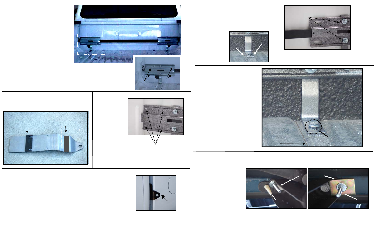
STEP 1 –[Hardware Kit A] Attach both backing (guide) plates to stabilizer bar. Using
#10 x ¾” sheet metal screws. See diagrams below for specific location.
Note
at both ends.
STEP 2 –[Hardware Kit C] Attach frame brace to guide plate by inserting the flat head,
square shouldered plow bolts through the countersunk hole in frame brace and securing
with flat washer, split lock washer and nut. See diagrams below for specific locations.
Note: Do not tighten the nuts at this time. They will be tightened at a later step.
While the FT-CG07 can be installed on any ’07 or newer Chevrolet/GMC
an extended cab with the rear swinging door.
DOING SO WILL RESULT IN DAMAGE TO THE DOOR
FRONT ANCHOR INSTALLATION
: The 4 large round holes in guide plate must be to the outer ends of the assembly
505 N. Kays Drive, Kaysville UT 84037
Phone: (801) 544-2585
Fax: (801) 546-5241
Email: happijac@happijac.com
Web Address: www.happijac.com
Center Slots
Page 2
STEP 3 –[Hardware Kit B]
Center the assembly against front
wall of truck. Select the screw
location (A or B) where the silver/gray
guide plate fits tightest against the
front wall and install self drilling
sheet metal screw provided. These
screws are used to hold the assembly
in place while drilling the mounting
holes for the anchor plates.
Generally only one screw per side is
needed. NOTE: Screws in position A
must be removed at a later step while
screws in position B may stay in place.
STEP 4 - SPACER INSTALLATION
Use double side adhesive strips to attach spacers at locations
shown to back (non printed side) of brac kets and/or guide plates)
STEP 5 –Drill
7
four
/16" holes
through guide
plate and bed
¼” thick
slotted spacer
1
/8” thick spacer
(optional)
R
E
ER
C
C
A
A
P
P
S
S
ER
C
A
P
S
front wall using
the four large
round holes
as a drill guide.
These holes
align with the threaded
holes in the black
anchor plate.
Anchor plate shown unpainted for clarity.
Caution: Do not strike the cab with the drill bit.
Placing a thin piece of plywood or other material
between the bed and cab may be helpful.
STEP 6 –[Hardware Kit B]
Remove the board (if used) from between bed & cab and insert the
B lack anchor plate. Start (do not tighten) all 4 bolts through guide
plate into threaded holes in black anchor plate.
Hint: The bolts will start easier if prior to installation
on truck, you run the bolts or a 3/8 -24 tap through the threaded holes
in the anchor plate to clear paint from the threads.
Cab
Once all bolts are started remove the screw
in position A or B (if used) then tighten all 4 bolts.
.
.
A
Mounting Holes
Cab
B
Anchor
Plate
2
STEP 7 – Set the “L” shaped frame
braces straight up and down, with the
foot along the outside edge of the bed
Frame Brace
Cab
Hardware
Set frame braces straight up & down.
3
weld seam, then tighten the nuts
holding the frame brace to the
guide plate.
Bed
Weld
Seam
Foot
Center the foot
In the bed flute.
.
.
STEP 8 –[Hardware Kit D]
Drill 3/8” dia. Hole through
frame brace foot, bed, and
frame/bed cross member
at location shown.
Make sure drill is as vertical
as possible in all directions.
STEP 9 – Insert 5” Carriage
bolt through hole and secure
x
from beneath truck with
hardware provided.
NOTE: The reinforcing plate
is not required on the drivers
side..
THIS COMPLETES THE FRONT ANCHOR INSTALLATION
x
Drill in line with center of bed bolt.
(Same distance from front wall)
Drill in line
with existing
Drain holes in bed
and to the outside
Of the bed weld
seam.
View looking up from beneath truck.
x
Drivers Side
Carriage bolt from top side of bed.
Bed alignment pin
Reinforcing
Plate
Carriage bolt from top side of bed.
This truck bed
shown with
spray in liner.
Carriage
Bolt
Passenger Side
 Loading...