


System 5000
Press Control
TONNAGE MONITOR
MODULE
COLOR DISPLAY
OPERATING MANUAL
LINK ELECTRIC & SAFETY CONTROL COMPANY
444 McNALLY DRIVE, |
NASHVILLE TN 37211 |
PH (615)-833-4168 |
FAX (615)-834-1984 |
5000 OmniLink

Table of Contents
Section 1 |
Introduction . |
. . . . . . . . . . . . . . . . . . . . . . . . . . . . . . . . . . . . . . . . . . . . . . . . . . . . . . . . . |
1.1 |
|
Section 1.1 |
Features . |
. . . . . . . . . . . . . . . . . . . . . . . . . . . . . . . . . . . . . . . . . . . . . . . . . . . . . . . . . |
1.1 |
|
Section 2 |
Parameter Entry and Access Control . . . . . . . . . . . . . . . . . . . . . . . . . . . . . . . . . . . . . . . |
2.1 |
||
Section 2.1 |
Parameter Entry . . . . . . . . . . . . . . . . . . . . . . . . . . . . . . . . . . . . . . . . . . . . . . . . . . . . |
2.1 |
||
Section 2.1.1 |
Numeric Entries . . . . . . . . . . . . . . . . . . . . . . . . . . . . . . . . . . . . . . . . . . . . . . . . . |
2.1 |
||
Section 2.1.2 |
Text Entry . . . . . . . . . . . . . . . . . . . . . . . . . . . . . . . . . . . . . . . . . . . . . . . . . . . . . |
2.1 |
||
Section 2.2 |
Access Control . . . . . . . . . . . . . . . . . . . . . . . . . . . . . . . . . . . . . . . . . . . . . . . . . . . . . |
2.3 |
||
Section 2.2.1 Key Only Mode . . . . . . . . . . . . . . . . . . . . . . . . . . . . . . . . . . . . . . . . . . . . . . . . . |
2.3 |
|||
Section 2.2.2 Key or Password Mode . . . . . . . . . . . . . . . . . . . . . . . . . . . . . . . . . . . . . . . . . . . |
2.3 |
|||
Section 2.2.3 Password Only Mode . . . . . . . . . . . . . . . . . . . . . . . . . . . . . . . . . . . . . . . . . . . . . |
2.4 |
|||
Section 2.2.4 Key and Password Mode . . . . . . . . . . . . . . . . . . . . . . . . . . . . . . . . . . . . . . . . . . |
2.4 |
|||
Section 2.2.5 Tonnage Monitor Restricted Items . . . . . . . . . . . . . . . . . . . . . . . . . . . . . . . . . . |
2.4 |
|||
Section 2.2.6 Access Control Operation . . . . . . . . . . . . . . . . . . . . . . . . . . . . . . . . . . . . . . . . . |
2.4 |
|||
Section 2.2.6.1 |
RUN/PROG Key Switch Operation . . . . . . . . . . . . . . . . . . . . . . . . . . . . |
2.5 |
||
Section 2.2.6.2 |
Password System Operation . . . . . . . . . . . . . . . . . . . . . . . . . . . . . . . . . |
2.5 |
||
Section 3 |
Definitions and Terminology . . . . . . . . . . . . . . . . . . . . . . . . . . . . . . . . . . . . . . . . . . . . . |
3.1 |
||
Section 3.1 |
Tonnage . |
. . . . . . . . . . . . . . . . . . . . . . . . . . . . . . . . . . . . . . . . . . . . . . . . . . . . . . . . . |
3.1 |
|
Section 3.1.1 |
Channel Tonnage . . . . . . . . . . . . . . . . . . . . . . . . . . . . . . . . . . . . . . . . . . . . . . . . |
3.1 |
||
Section 3.1.2 |
Total Tonnage . . . . . . . . . . . . . . . . . . . . . . . . . . . . . . . . . . . . . . . . . . . . . . . . . . |
3.1 |
||
Section 3.1.3 |
Reverse Tonnage . . . . . . . . . . . . . . . . . . . . . . . . . . . . . . . . . . . . . . . . . . . . . . . . |
3.3 |
||
Section 3.2 |
Data Windows . . . . . . . . . . . . . . . . . . . . . . . . . . . . . . . . . . . . . . . . . . . . . . . . . . . . . |
3.4 |
||
Section 3.2.1 Data Window On Angle . . . . . . . . . . . . . . . . . . . . . . . . . . . . . . . . . . . . . . . . . . . |
3.4 |
|||
Section 3.2.2 |
Data Window Off Angle . . . . . . . . . . . . . . . . . . . . . . . . . . . . . . . . . . . . . . . . . . |
3.5 |
||
Section 3.3 |
Limits . . . |
. . . . . . . . . . . . . . . . . . . . . . . . . . . . . . . . . . . . . . . . . . . . . . . . . . . . . . . . . |
3.6 |
|
Section 3.3.1 Machine Rating Limit . . . . . . . . . . . . . . . . . . . . . . . . . . . . . . . . . . . . . . . . . . . . |
3.6 |
|||
Section 3.3.2 |
Low Limits . . . . . . . . . . . . . . . . . . . . . . . . . . . . . . . . . . . . . . . . . . . . . . . . . . . . . |
3.6 |
||
Section 3.3.3 |
High Limits . . . . . . . . . . . . . . . . . . . . . . . . . . . . . . . . . . . . . . . . . . . . . . . . . . . . |
3.6 |
||
Section 3.3.4 |
Reverse Limits . . . . . . . . . . . . . . . . . . . . . . . . . . . . . . . . . . . . . . . . . . . . . . . . . . |
3.6 |
||
Section 3.3.5 Total Tonnage Limit . . . . . . . . . . . . . . . . . . . . . . . . . . . . . . . . . . . . . . . . . . . . . |
3.7 |
|||
Section 4 |
Operation . . . |
. . . . . . . . . . . . . . . . . . . . . . . . . . . . . . . . . . . . . . . . . . . . . . . . . . . . . . . . . |
4.1 |
|
Section 4.1 |
Main Operator Terminal Screen . . . . . . . . . . . . . . . . . . . . . . . . . . . . . . . . . . . . . . . |
4.1 |
||
Section 4.2 |
Main Tonnage Monitor Screen . . . . . . . . . . . . . . . . . . . . . . . . . . . . . . . . . . . . . . . . |
4.2 |
||
Section 4.2.1 Selecting a View . . . . . . . . . . . . . . . . . . . . . . . . . . . . . . . . . . . . . . . . . . . . . . . . |
4.5 |
|||
Section 4.2.1.1 |
Viewing the Peak and Data Window Tonnages and Settings . . . . . . . . |
4.6 |
||
Section 4.2.1.2 |
Showing Forward and Reverse Tonnage . . . . . . . . . . . . . . . . . . . . . . . . |
4.6 |
||
Section 4.2.2 |
Setting Limits . . . . . . . . . . . . . . . . . . . . . . . . . . . . . . . . . . . . . . . . . . . . . . . . . . . |
4.6 |
||
Section 4.2.2.1 |
Setting High Limits . . . . . . . . . . . . . . . . . . . . . . . . . . . . . . . . . . . . . . . . |
4.6 |
||
Section 4.2.2.2 |
Setting Low Limits . . . . . . . . . . . . . . . . . . . . . . . . . . . . . . . . . . . . . . . . |
4.6 |
||
Section 4.2.2.3 |
Setting Reverse Limits . . . . . . . . . . . . . . . . . . . . . . . . . . . . . . . . . . . . . . |
4.7 |
||
Section 4.2.2.4 |
Automatically Setting Limits . . . . . . . . . . . . . . . . . . . . . . . . . . . . . . . . . |
4.7 |
||
Section 4.2.2.5 |
Turning Low Limits ON or OFF . . . . . . . . . . . . . . . . . . . . . . . . . . . . . . |
4.8 |
||
April 17, 2000 Man ual Revisio n 1.0
i

Section 4.2.2.6 Turning Reverse Limits ON or OFF . . . . . . . . . . . . . . . . . . . . . . . . . . . |
4.8 |
|||
Section 4.2.3 Setting Additional Data Window Parameters . . . . . . . . . . . . . . . . . . . . . . . . . . |
4.8 |
|||
Section 4.2.3.1 Turning Data Windows ON or OFF . . . . . . . . . . . . . . . . . . . . . . . . . . . |
4.8 |
|||
Section 4.2.3.2 Setting the Data Window “Start Angle” . . . . . . . . . . . . . . . . . . . . . . . . |
4.8 |
|||
Section 4.2.3.3 Setting the Data Window “End Angle” . . . . . . . . . . . . . . . . . . . . . . . . . |
4.8 |
|||
Section 4.2.4 Bypassing the Tonnage Monitor . . . . . . . . . . . . . . . . . . . . . . . . . . . . . . . . . . . . |
4.9 |
|||
Section 4.2.5 The GRAPH OPERATIONS Softkey . . . . . . . . . . . . . . . . . . . . . . . . . . . . . . . . |
4.9 |
|||
Section 4.2.6 The SLIDE ADJUST Softkey . . . . . . . . . . . . . . . . . . . . . . . . . . . . . . . . . . . . . . |
4.9 |
|||
Section 4.2.7 The MOTOR SPEED Softkey . . . . . . . . . . . . . . . . . . . . . . . . . . . . . . . . . . . . . . |
4.9 |
|||
Section 4.2.8 The CONFIGURE TON MON Softkey . . . . . . . . . . . . . . . . . . . . . . . . . . . . . . |
4.9 |
|||
Section 4.3 |
Tonnage Alarms/Stop Conditions . . . . . . . . . . . . . . . . . . . . . . . . . . . . . . . . . . . . . |
4.10 |
||
Section 4.3.1 |
Low Alarm . . . . . . . . . . . . . . . . . . . . . . . . . . . . . . . . . . . . . . . . . . . . . . . . . . . . |
4.10 |
||
Section 4.3.2 High Peak Alarm . . . . . . . . . . . . . . . . . . . . . . . . . . . . . . . . . . . . . . . . . . . . . . . |
4.10 |
|||
Section 4.3.3 High Data Window Alarm . . . . . . . . . . . . . . . . . . . . . . . . . . . . . . . . . . . . . . . . |
4.11 |
|||
Section 4.3.4 |
Reverse Alarm . . . . . . . . . . . . . . . . . . . . . . . . . . . . . . . . . . . . . . . . . . . . . . . . . |
4.11 |
||
Section 4.3.5 Machine Rating Alarm . . . . . . . . . . . . . . . . . . . . . . . . . . . . . . . . . . . . . . . . . . . |
4.12 |
|||
Section 4.3.6 TOTAL Alarm/Stop Condition . . . . . . . . . . . . . . . . . . . . . . . . . . . . . . . . . . . . |
4.12 |
|||
Section 4.4 |
Error Conditions . . . . . . . . . . . . . . . . . . . . . . . . . . . . . . . . . . . . . . . . . . . . . . . . . . . |
4.13 |
||
Section 4.4.1 |
Setpoint Errors . . . . . . . . . . . . . . . . . . . . . . . . . . . . . . . . . . . . . . . . . . . . . . . . . |
4.13 |
||
Section 4.4.2 |
Channel Errors . . . . . . . . . . . . . . . . . . . . . . . . . . . . . . . . . . . . . . . . . . . . . . . . . |
4.13 |
||
Section 4.4.3 |
Resetting Errors . . . . . . . . . . . . . . . . . . . . . . . . . . . . . . . . . . . . . . . . . . . . . . . . |
4.14 |
||
Section 4.5 The Tonnage Monitor Graph Screen . . . . . . . . . . . . . . . . . . . . . . . . . . . . . . . . . . . |
4.15 |
|||
Section 4.5.1 Viewing the Graph . . . . . . . . . . . . . . . . . . . . . . . . . . . . . . . . . . . . . . . . . . . . . . |
4.19 |
|||
Section 4.5.1.1 |
Graph Start Angle . . . . . . . . . . . . . . . . . . . . . . . . . . . . . . . . . . . . . . . . |
4.19 |
||
Section 4.5.1.2 |
Graph End Angle . . . . . . . . . . . . . . . . . . . . . . . . . . . . . . . . . . . . . . . . . |
4.19 |
||
Section 4.5.1.3 |
Graph Scale . . . . . . . . . . . . . . . . . . . . . . . . . . . . . . . . . . . . . . . . . . . . . |
4.19 |
||
Section 4.5.1.4 |
Panning the Graph . . . . . . . . . . . . . . . . . . . . . . . . . . . . . . . . . . . . . . . . |
4.20 |
||
Section 4.5.1.5 Selecting the Channel . . . . . . . . . . . . . . . . . . . . . . . . . . . . . . . . . . . . . |
4.20 |
|||
Section 4.5.2 Graphically Setting Values . . . . . . . . . . . . . . . . . . . . . . . . . . . . . . . . . . . . . . . |
4.20 |
|||
Section 4.5.3 Sending the Graph . . . . . . . . . . . . . . . . . . . . . . . . . . . . . . . . . . . . . . . . . . . . . . |
4.21 |
|||
Section 4.5.3.1 Store As Reference . . . . . . . . . . . . . . . . . . . . . . . . . . . . . . . . . . . . . . . . |
4.21 |
|||
Section 4.5.3.2 |
Send To Laptop . . . . . . . . . . . . . . . . . . . . . . . . . . . . . . . . . . . . . . . . . . |
4.21 |
||
Section 4.5.3.3 |
Send To Network . . . . . . . . . . . . . . . . . . . . . . . . . . . . . . . . . . . . . . . . . |
4.22 |
||
Section 4.5.3.4 Archive To Network . . . . . . . . . . . . . . . . . . . . . . . . . . . . . . . . . . . . . . |
4.22 |
|||
Section 4.5.3.5 |
Print To Network . . . . . . . . . . . . . . . . . . . . . . . . . . . . . . . . . . . . . . . . . |
4.22 |
||
Section 4.5.4 |
|
Reference Waveforms . . . . . . . . . . . . . . . . . . . . . . . . . . . . . . . . . . . . . . . . |
4.22 |
|
Section 5 |
Configuration . . . . . . . . . . . . . . . . . . . . . . . . . . . . . . . . . . . . . . . . . . . . . . . . . . . . . . . . . |
5.1 |
||
Section 5.1 Tonnage Monitor Machine Settings . . . . . . . . . . . . . . . . . . . . . . . . . . . . . . . . . . . . . |
5.1 |
|||
Section 5.1.1 High Peak Alarm Stop . . . . . . . . . . . . . . . . . . . . . . . . . . . . . . . . . . . . . . . . . . . . |
5.2 |
|||
Section 5.1.2 High Data Window Alarm Stop . . . . . . . . . . . . . . . . . . . . . . . . . . . . . . . . . . . . . |
5.2 |
|||
Section 5.1.3 Number of Data Windows . . . . . . . . . . . . . . . . . . . . . . . . . . . . . . . . . . . . . . . . . |
5.2 |
|||
Section 5.1.4 |
Channel Configuration . . . . . . . . . . . . . . . . . . . . . . . . . . . . . . . . . . . . . . . . . . . . |
5.3 |
||
Section 5.1.4 Reset Only in Program . . . . . . . . . . . . . . . . . . . . . . . . . . . . . . . . . . . . . . . . . . . . |
5.3 |
|||
Section 5.1.5 Zero Integration Time . . . . . . . . . . . . . . . . . . . . . . . . . . . . . . . . . . . . . . . . . . . . |
5.3 |
|||
Section 5.1.6 Graph Sample Rate . . . . . . . . . . . . . . . . . . . . . . . . . . . . . . . . . . . . . . . . . . . . . . |
5.3 |
|||
Section 5.1.7 |
Start Sample Window Angle . . . . . . . . . . . . . . . . . . . . . . . . . . . . . . . . . . . . . . . |
5.4 |
||
April 17, 2000 Man ual Revisio n 1.0
ii

Section 5.1.8 End Sample Window Angle . . . . . . . . . . . . . . . . . . . . . . . . . . . . . . . . . . . . . . . . |
5.4 |
||
Section 5.1.9 Erase All Setups . . . . . . . . . . . . . . . . . . . . . . . . . . . . . . . . . . . . . . . . . . . . . . . . . |
5.4 |
||
Section 5.2 |
Machine Rating . . . . . . . . . . . . . . . . . . . . . . . . . . . . . . . . . . . . . . . . . . . . . . . . . . . . |
5.5 |
|
Section 5.2.1 |
Decimal Point . . . . . . . . . . . . . . . . . . . . . . . . . . . . . . . . . . . . . . . . . . . . . . . . . . . |
5.5 |
|
Section 5.2.2 Derate Total Tonnage . . . . . . . . . . . . . . . . . . . . . . . . . . . . . . . . . . . . . . . . . . . . . |
5.5 |
||
Section 5.3 |
Calibration Screens . . . . . . . . . . . . . . . . . . . . . . . . . . . . . . . . . . . . . . . . . . . . . . . . . |
5.7 |
|
Section 5.3.1 |
Dynamic Calibration . . . . . . . . . . . . . . . . . . . . . . . . . . . . . . . . . . . . . . . . . . . . . |
5.7 |
|
Section 5.3.2 |
Static Calibration . . . . . . . . . . . . . . . . . . . . . . . . . . . . . . . . . . . . . . . . . . . . . . . . |
5.7 |
|
Section 5.3.3 |
Channel Descriptions . . . . . . . . . . . . . . . . . . . . . . . . . . . . . . . . . . . . . . . . . . . . . |
5.7 |
|
Section 5.4 |
Reset Alarm Counters . . . . . . . . . . . . . . . . . . . . . . . . . . . . . . . . . . . . . . . . . . . . . . . |
5.8 |
|
Section 6 |
Job Setups . . . . . . . . . . . . . . . . . . . . . . . . . . . . . . . . . . . . . . . . . . . . . . . . . . . . . . . . . . . |
6.1 |
|
Section 6.1 |
New Die Installation . . . . . . . . . . . . . . . . . . . . . . . . . . . . . . . . . . . . . . . . . . . . . . . . |
6.1 |
|
Section 7 |
Installation . . . . . . . . . . . . . . . . . . . . . . . . . . . . . . . . . . . . . . . . . . . . . . . . . . . . . . . . . . . |
7.1 |
|
Section 7.1 |
Module Location . . . . . . . . . . . . . . . . . . . . . . . . . . . . . . . . . . . . . . . . . . . . . . . . . . . |
7.1 |
|
Section 7.2 |
Strain Gauge Locations . . . . . . . . . . . . . . . . . . . . . . . . . . . . . . . . . . . . . . . . . . . . . . |
7.2 |
|
Section 7.2.1 "C" Frame Machines . . . . . . . . . . . . . . . . . . . . . . . . . . . . . . . . . . . . . . . . . . . . . |
7.2 |
||
Section 7.2.2 Straight Side Machines . . . . . . . . . . . . . . . . . . . . . . . . . . . . . . . . . . . . . . . . . . . |
7.2 |
||
Section 7.3 |
Strain Gauge Mounting . . . . . . . . . . . . . . . . . . . . . . . . . . . . . . . . . . . . . . . . . . . . . . |
7.6 |
|
Section 7.3.1 Direct Machine Mounting . . . . . . . . . . . . . . . . . . . . . . . . . . . . . . . . . . . . . . . . . |
7.6 |
||
Section 7.3.2 Intermediate Weld Pad Mounting . . . . . . . . . . . . . . . . . . . . . . . . . . . . . . . . . . . |
7.7 |
||
Section 7.4 |
Strain Gauge Wiring . . . . . . . . . . . . . . . . . . . . . . . . . . . . . . . . . . . . . . . . . . . . . . . . |
7.8 |
|
Section 7.5 |
Installation Procedure . . . . . . . . . . . . . . . . . . . . . . . . . . . . . . . . . . . . . . . . . . . . . . . |
7.9 |
|
Section 7.6 |
Configuring Control . . . . . . . . . . . . . . . . . . . . . . . . . . . . . . . . . . . . . . . . . . . . . . . . |
7.11 |
|
Section 8 |
Calibration . . . . . . . . . . . . . . . . . . . . . . . . . . . . . . . . . . . . . . . . . . . . . . . . . . . . . . . . . . . |
8.1 |
|
Section 8.1 |
Dynamic Calibration with Load Cells . . . . . . . . . . . . . . . . . . . . . . . . . . . . . . . . . . . |
8.3 |
|
Section 8.2 |
Static Calibration with Hydraulic Jacks . . . . . . . . . . . . . . . . . . . . . . . . . . . . . . . . . . |
8.6 |
|
Section 8.3 |
Replacing System 1000/1100 . . . . . . . . . . . . . . . . . . . . . . . . . . . . . . . . . . . . . . . . . |
8.9 |
|
Section 8.4 |
Calibration Numbers . . . . . . . . . . . . . . . . . . . . . . . . . . . . . . . . . . . . . . . . . . . . . . . . |
8.9 |
|
Section 8.5 |
Incorrect Tie Rod Tension . . . . . . . . . . . . . . . . . . . . . . . . . . . . . . . . . . . . . . . . . . . . |
8.9 |
|
Section 9 Troubleshooting . . . . . . . . . . . . . . . . . . . . . . . . . . . . . . . . . . . . . . . . . . . . . . . . . . . . . . . 9.1 Section 9.1 Communication Failure . . . . . . . . . . . . . . . . . . . . . . . . . . . . . . . . . . . . . . . . . . . . . . 9.1 Section 9.2 Diagnostic LEDs . . . . . . . . . . . . . . . . . . . . . . . . . . . . . . . . . . . . . . . . . . . . . . . . . . . 9.1
Section 10 . . . . . . . . . . . . . . . . . . . . . . . . . . . . . . . . . . . . . . . . . . . . . . . . . . . . . . . . . . . . . . . . . . . . . . . 10.1 Section 10.1 Software Version . . . . . . . . . . . . . . . . . . . . . . . . . . . . . . . . . . . . . . . . . . . . . . . . . . 10.1 Section 10.2 Configuration Code and Clear Stroke Counter/Memory Code . . . . . . . . . . . . . . . 10.1
April 17, 2000 Man ual Revisio n 1.0
iii

April 17, 2000 Man ual Revisio n 1.0
iv

Section 1 |
Introduction |
The Tonnage Monitor module is an optional addition to the OmniLink 5000 Press Control intended to measure and display the force being applied to the frame of a mechanical power press. The force applied during the working portion of the stroke is compared with allowable limits based on the capacity of the machine and correct operation of the die and material being used. Tonnages beyond these limits cause various types of stop signals to be sent to the press control depending upon the importance of the overload. Present tonnage readings, status messages, present tonnage limits, and detailed tonnage versus angle graphs (signatures) can be examined or programmed through the same Operator Terminal as all other OmniLink 5000 settings.
Section 1.1 Features
‚The 5000-8A Tonnage Monitor Module provides four strain connections for use on two or four channel machines.
‚A crankshaft angle with a resolution of .021 degrees is supplied to the module by an internal communication with the Press Control Logic Board. Position dependent parameters such as the working portion of the stroke or data window settings are entered directly into the Tonnage Monitor Module requiring no external cam switches.
‚The same internal communication allows the module to instruct the press control to Top Stop, Cycle Stop, or Cycle Stop and turn Off the hydraulic overload outputs depending on the present stroking mode and the type of tonnage alarm that has occurred.
‚Within the working portion of the stroke tonnage, limits for each job can be set for the maximum allowable forward tonnage (High Limit), minimum required forward tonnage (Low Limit), and maximum allowable reverse tonnage (Reverse Limit).
‚Inside the monitoring region additional data windows can be set to become active at specific crankshaft angles, creating additional Low and High limits that become active only for the region specified. Up to four data windows can be programmed for each job.
‚A maximum allowable forward tonnage limit is established when the module is installed, based on the capacity of the machine (Machine Rating) and cannot be turned Off.
‚If desired, additional limits can be placed on the total tonnage that reflect the maximum allowable tonnage at specific positions in the stroke.
‚Limits can be programmed manually, automatically calculated by the Tonnage Monitor Module, or recalled along with all other OmniLink 5000 settings through the use of job setups.
‚Tonnage alarm counters are maintained for low, high, machine, and reverse tonnage alarms.
‚Status messages for each channel indicate the first alarm condition that occurred during the stroke.
‚Each channel can be configured with a 15 character description indicating its physical location on the
April 17, 2000 Man ual Revisio n 1.0 |
1.1 |

press.
‚A graph of tonnage versus crankshaft angle can be displayed for each channel or the total. This graph also shows the active areas of the data windows, when used.
‚A reference waveform can be stored for each job.
April 17, 2000 Man ual Revisio n 1.0 |
1.2 |

Section 2 Parameter Entry and Access Control
Section 2.1 Parameter Entry
Throughout the OmniLink control, a fairly standard form of data entry is employed. When data entry is allowed, an “editing cursor” will appear on the screen. This cursor can typically be moved from parameter to parameter on the screen with the up, down, left, and right arrow keys. The topmost softkey is used to select the parameter for editing and can change description depending on the parameter selected.
Section 2.1.1 Numeric Entries
Assuming access has been achieved by one of the means listed in the following sections, to change a numeric value:
a)Place the editing cursor on the parameter to be changed by using the up, down, left, and right arrow keys as appropriate. Note that the editing cursor will only appear on the screen when editing is allowed. For instance, editing is usually not allowed when the press is running.
b)The topmost softkey will usually say something along the lines of “CHANGE XXXXXX” where XXXXXX is the name of the value to be changed. It may also simply say “CHANGE NUMBER.” In any case, hit this softkey to enter numeric input mode. The editing cursor will change to a rectangle around the parameter to be edited.
c)Use the numeric keypad to input the new number desired for the parameter.
d)Press the ENT key to finish.
Note that moving off the parameter with the arrow keys or hitting the EXIT key will abort the edit and leave the parameter at the value it had before the editing process began.
Section 2.1.2 Text Entry
For text entry:
a)Place the editing cursor on the text to be changed by using the up, down, left, and right arrow keys as appropriate. Note that the editing cursor will only appear on the screen when editing is allowed. For instance, editing is usually not allowed when the press is running.
b)The topmost softkey will usually say something along the lines of “CHANGE XXXXXX” where XXXXXX is the name of the value to be changed. It may also simply say “CHANGE TEXT.” In any case, hit this softkey to enter text entry mode. The right-hand softkeys will change, a letter selection box will appear, and the editing cursor will change to a rectangle around the text to be edited. Figure 2.1 shows the softkeys and an example text parameter.
April 17, 2000 Man ual Revisio n 1.0 |
2.1 |
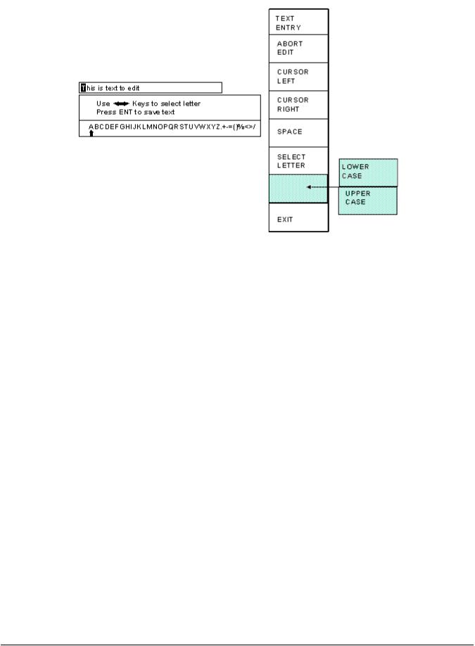
Figure 2.1: Example Text Entry
c)The fist character of the text is highlighted with the text cursor. The CURSOR LEFT and CURSOR RIGHT softkeys will move this cursor.
d)Use the left and right arrow keys to point to the letter desired in the letter box next to the text being edited. This box will just appear above or just below the text to be edited depending on where it is in the screen. Hit the SELECT LETTER softkey to place that letter at the text cursor. In the example above, the text cursor is on the “T” in “This” and would be replaced with an “A”. The text cursor will automatically move to the right when a letter is selected. Note that numerals can be entered directly with the numeric keypad.
e)The SPACE softkey can be used to enter a space character in the text.
f)The softkey immediately above the EXIT softkey is used to select between uppercase and lowercase letters.
g)The EXIT or ABORT EDIT softkeys can be used to abort the editing operation. The text will revert to what it was before the editing operation started.
h)After the text has been changed as desired, press the ENT key to accept the changes.
April 17, 2000 Man ual Revisio n 1.0 |
2.2 |
Section 2.2 Access Control
The OmniLink control has several parameters or operations that have limited access. In regards to the tonnage monitor the ability to perform actions of turning bypass off and on, resetting faults, or changing limits must be restricted to certain personnel. The OmniLink control provides several means to limit access to these parameters or operations. These parameters and operations are called restricted items.
The OmniLink control employs combinations of two different means to limit access to restricted items. These means are the RUN/PROG key switch on the operator terminal and a user password system. The user password system assigns names and passwords to up to sixteen users. These two means can be used alone or in combination with each other. When a user employs the proper means to gain access, he will have the ability to perform the actions and change the parameters which have been designated to his control.
There are four possible modes of operation for the restricted access system. They are the “Key Only” mode, the “Key or Password” mode, the “Password Only” mode, and the “Key and Password” mode. The control can be configured to operate in any one of these four modes.
Section 2.2.1 Key Only Mode
The “Key Only” mode is the least complex of the four modes. This mode employs the RUN/PROG key as the only means to limit access to restricted items. Any user with the RUN/PROG key can access all of the restricted items. Without the RUN/PROG key, user access to all of the restricted items is prohibited.
Although the “Key Only” mode has the advantage of being easy to use, it does have a disadvantage. This mode cannot give a particular user access to only some of the restricted items. When operating in this mode, any user with the RUN/PROG key will have access to all of the restricted items.
Section 2.2.2 Key or Password Mode
The key or password mode allows for either of two means to gain access to the restricted items. A user with RUN/PROG key can access all of the restricted items. A user with the correct password can access the restricted items that have been designated for that particular user’s access only. The system allows for passwords to be assigned to sixteen users. Each user can be assigned access to any or all of the restricted items.
The following is an example of a “Key or Password” mode operation. The RUN/PROG key is given to the die set-up personnel. A press operator is assigned a user name and password. With the password the operator can reset tonnage monitor faults. This is the only tonnage monitor related item to which the operator has access. In order to load a die, the set-up personnel uses the RUN/PROG key to recall a job from job storage. The set-up personnel will also be able to make changes to tonnage monitor limits. Once the set-up personnel sets the die and verifies its correct operation, the operator is left to run the die. If a tonnage monitor fault occurs, the operator can enter the correct password and then reset the fault. However, the operator cannot change tonnage monitor limits or bypass the tonnage monitor. This will allow the operator to keep running the job and reset faults that occur. However, if consistent stops occur because a tonnage monitor limit needs changing, the set-up personnel must be called to change the
April 17, 2000 Man ual Revisio n 1.0 |
2.3 |

tonnage monitor limit.
The example above can be taken one additional step, if two press operators are given different user names and different passwords. One operator can be assigned the ability to change tonnage monitor limits in addition to the ability to reset tonnage monitor faults, while the other operator is not assigned the ability to change the tonnage monitor limits.
Section 2.2.3 Password Only Mode
The “Password Only” mode allows for sixteen users. Each user can be assigned access to some or all of the restricted items. This mode does not use the RUN/PROG key.
The example listed above indicated that setup personnel required access to all restricted items. In the “Key or Password” mode, the setup personnel used the RUN/PROG key to gain access to all of the restricted items. In the “Password Only” mode, the setup personnel can still have access to all of the restricted items, but the system must be configured as such. The setup personnel must be assigned a user name and password. In addition, all restricted items would be assigned access to the setup personnel.
Section 2.2.4 Key and Password Mode
The “Key and Password” mode requires the user to have the RUN/PROG key, user name, and user password. Operation is basically the same as the Password only mode, except that in addition to entering the password the user must switch the RUN/PROG key to the PROG position.
Section 2.2.5 Tonnage Monitor Restricted Items
The following table lists the tonnage monitor restricted items name and function.
|
TONNAGE MONITOR RESTRICTED ITEMS |
NAME |
FUNCTION |
TM Bypass |
Bypass the Tonnage Monitor |
TM Reset |
Reset Tonnage Monitor Faults |
TM Peak High Limits |
Change the Tonnage Monitor Peak High Limits |
TM Peak Low Limits |
Change the Tonnage Monitor Peak Low Limits |
TM Reverse Limits |
Change the Tonnage Monitor Reverse Limits |
TM Auto Setup |
Perform a Tonnage Monitor Automatic Setup |
TM Data Windows |
Change the Tonnage Monitor Data Windows High Limits, Low |
|
Limits, Start Angle, and Stop Angle |
Section 2.2.6 Access Control Operation
April 17, 2000 Man ual Revisio n 1.0 |
2.4 |

To gain access control the user must use one of two means or a combination of these two means. These means are the RUN/PROG key or the user password system.
Section 2.2.6.1 RUN/PROG Key Switch Operation
The RUN/PROG key switch is located on the lower right side of the operator terminal. This is a two position switch. The key is removable in the RUN position only. If the RUN/PROG key switch is being used as a means to access the restricted items, the switch must be turned to the PROG position. When the RUN/PROG key switch is switched to the PROG position, the press will Top Stop and stroking will be prohibited until the switch is returned to the RUN position.
When operating in the Key Only mode the key switch is the only means available to access the restricted items. All restricted items are accessible when the RUN/PROG key switch is switched to the PROG position.
When operating in the “Key or Password” mode, the key switch is one of the means available to access the restricted items. All restricted items are accessible when the RUN/PROG key switch is switched to the PROG position.
When operating in the “Key and Password” mode, the key switch and password must be used to access the restricted items. In this mode, the user will be granted access only to the restricted items that have been assigned to him.
Section 2.2.6.2 Password System Operation
Figure 2.2 displays a typical password entry sequence. This example shows the steps necessary to change a tonnage monitor limit setting. This is typical for password entry for all restricted items.
April 17, 2000 Man ual Revisio n 1.0 |
2.5 |

Figure 2.2: Password Entry Sequence
Step A: Select the restricted item. In the example shown in Figure 2.2 the restricted item is Channel 2 High Limit. Once the parameter is selected then Softkey # 1, the upper vertical softkey (Softkey # 1 is highlighted in Figure 2.2) , will display the legend “SELECT”.
Step B: A list of users that have access to this restricted item will appear. In the example shown in Figure 2.2 only User Number One, User Number Two, and User Number Five have access to this restricted parameter. The system may have several more users, but the three users listed on the screen are the only users that have access to change a High Peak Limit. The user must use the arrow keys to position the cursor on his user name. After placing the cursor on the correct name, the user must press the SELECT softkey. The SELECT softkey must be pressed even if there is only one user name displayed.
Step C: The display will show the selected user name and request the user password. The user must enter the correct password and then press the ENT key.
Step D: Upon entry of the correct password, the user will be allowed access to the restricted item. In the example shown in Figure 2.2, the user will have access to change the Channel 2 High Limit.
After performing the steps listed above, the user will be logged in to the password system. The user will
April 17, 2000 Man ual Revisio n 1.0 |
2.6 |

have access to all restricted items that have been designated for his access. This access will remain until the user performs a log out or until the user is automatically logged out.
The user can log out by using the ACC key. This key will directly switch the display to the Quick Access screen. The LOGOUT soft key legend will appear along the bottom of the screen. If the operator presses this key, he will log out. He will no longer have access to the restricted items, unless he repeats steps A through D.
In addition to the manual log out, the system contains an automatic logout. The intent of automatic log out is to reduce the possibility of users other than the intended user having access to restricted items. If there were no provisions for automatic log out and a user forgot to manually log out, all restricted items to which the user had been designated for access would be available from the log in time until power was removed from the OmniLink control. This presents the possibility of users other than the intended user having access to restricted items. Automatic log out is based upon both time and press strokes. During system configuration automatic Access Timeout parameters are entered. An automatic access timeout time and automatic access timeout strokes are entered. The time entered is the amount of time after the last key stroke that will be allowed before the system will automatically log out the user. For example, if the automatic access timeout is set to 60 seconds, the user will be logged out 60 seconds after the last key stroke. If the user presses a key before the 60 seconds have elapsed, a new 60 second cycle will be started. The number of strokes that are entered is the number of press strokes after the last key stroke that will be allowed before the system automatically logs out the user. For example, if the automatic timeout is set to 10 strokes, the user will be logged out when the press completes ten strokes after the last key stroke. If the user presses a key before 10 strokes have been completed, a new 10 stroke cycle will be started.
April 17, 2000 Man ual Revisio n 1.0 |
2.7 |

Section 3 Definitions and Terminology
This section will give some background and explain the meaning of various settings and readings in the tonnage monitor. It is strongly recommended that this section be read in order to use the tonnage monitor effectively!
Section 3.1 Tonnage
The tonnage monitor reads forming forces (“tonnage”) from strain gauges mounted on the machine frame. Each strain gauge is a “channel”. Tonnage monitors typically have two or four strain gauges depending on the type of machine. For example, OBI presses typically use two strain gauges (one on each side), while straight side presses typically use four strain gauges (one on each corner). Section 7 covers gauge mounting considerations and procedures.
Section 3.1.1 Channel Tonnage
A channel tonnage is the tonnage read from a single strain gauge. A numerical channel tonnage reading shown by the tonnage monitor is the highest tonnage exerted on that channel through the stroke or data window (data windows are discussed in section 3.2). In addition, the tonnage monitor can show the tonnage waveform for a channel. This waveform shows how the tonnage varies with press crankshaft angle.
Section 3.1.2 Total Tonnage
In addition to recording the maximum tonnage measured for each channel, the tonnage monitor module calculates and records the instantaneous summation of all channels. It performs the same peak measurement on this value as is performed on the individual channels. This value is displayed as the total tonnage exerted on the machine frame at any single position in the stroke.
When forces occur on all channels at the same time, the maximum total tonnage is the summation of the maximum channel tonnages. For example, the die shown in Figure 3.1 contains two equally sharp punches of equal cross-sectional area and equal length.
Figure 3.1: Example Die 1
This die is located in the center of an OBI press bed equipped with a two channel tonnage monitor with strain gauges mounted on both sides of the press frame. If the tonnage required for each punch is 100
April 17, 2000 Man ual Revisio n 1.0 |
3.1 |

tons and both punches impact the material at the same position in the stroke (at the same time) the graph in Figure 3.2 shows the forces applied to the left and right sides of the machine frame along with the resulting total force. This process would result in the tonnage monitor displaying 100 tons for the left channel, 100 tons for the right channel, and 200 tons for the total.
Figure 3.2: Tonnages From Example Die 1
When forces occur on the individual channels at different positions in the stroke (at different times), the total force depends on the amount of force exerted at any specific position. If the die described in the previous example had punches of different lengths as shown in Figure 3.3, the punches would not impact the material at the same position in the stroke.
Figure 3.3: Example Die 2
The graph in Figure 3.4 shows that the punch on the left contacts the material first and exerts a total force of 100 tons at time t1, with 60 tons distributed to left side of the machine frame and 40 tons distributed to the right. After the left punch breaks through the material, and at a different position in the
April 17, 2000 Man ual Revisio n 1.0 |
3.2 |

stroke, the punch on the right contacts the material and exerts a total force of 100 tons at time t2, with 60 tons distributed to the right side of the machine frame and 40 tons distributed to the left. This process would result in the tonnage monitor displaying that the maximum tonnage measured on the left side of the machine frame was 60 tons, that the maximum tonnage measured on the right side of the machine frame was 60 tons, and that the maximum total tonnage exerted on the machine frame was 100 tons.
Figure 3.4: Tonnages from Example Die 2
Section 3.1.3 Reverse Tonnage
In addition to monitoring the “forward” tonnages for a press, the tonnage monitor also measures and monitors the “reverse” tonnage. A press frame acts as a kind of stiff spring. When exerting tonnage in the down part of the cycle, portions of the press frame stretch proportionally to the tonnage exerted. In the case of a punch, for example, the tooling comes down and contacts the material. The press frame starts stretching, and this generates tonnage exerted on the material. Finally the tonnage exerted is sufficient for the punch to “break through” the material, and when it does the press frame tries to “spring back” to its original shape. Just like a regular spring, the press will overshoot its original resting position due to inertia and will actually compress instead of stretch. The tonnage registered on the frame during this “rebound” is the reverse tonnage. Reverse tonnages are typically much harder on the press than forward tonnages. As a result, press manufactures typically allow much less reverse tonnage on a machine than forward tonnage. For instance, a 500 ton machine may only be rated for 50 tons of reverse load.
April 17, 2000 Man ual Revisio n 1.0 |
3.3 |

Section 3.2 Data Windows
Peak tonnage monitors capture the maximum tonnage seen by each strain gauge over the stroke. This maximum tonnage is used for comparison to setpoints in determining if an alarm should be generated to stop the production process. While this is adequate for most applications, complex tooling can produce multiple peaks resulting in only the highest peak being checked against setpoints. Where closer monitoring is desired in these applications, the tonnage monitor module provides up to four “Data Windows” to monitor additional peaks other than the absolute maximum peak tonnage. These additional peaks are referred to as “local” peaks. Each data window consists of a separate high and low limit that are used from a given start angle to a given end angle.
The tonnage graph in Figure 3.5A is for a two station die. The first station cuts out the part (local peak), and the second station stamps a logo onto the part (absolute peak).
Since the tonnage required to coin the logo is greater than the tonnage required to cut the part, the local peak is not checked using a normal peak tonnage monitor. The local peak could completely disappear and a normal peak tonnage monitor would not detect any anomaly in the process since the absolute peak limits are still being satisfied by the coining part of the die. This is exactly what would happen if the material did not feed between strokes as shown in Figure 3.5B. Using a single data window, however, places a separate high and low limit on the local peak.
Figure 3.5: Example Data Window.
Section 3.2.1 Data Window On Angle
The On Angle for a data window is the angle at which the setpoints for that data window start to be enforced. For example, in Figure 3.5, data window 1 has an on angle of 165 degrees.
April 17, 2000 Man ual Revisio n 1.0 |
3.4 |

Section 3.2.2 Data Window Off Angle
The Off Angle for a data window is the angle at which the setpoints for that data window stop being enforced. For example, in Figure 3.5, data window 1 has an off angle of 170 degrees.
Section 3.3 |
Limits |
The tonnage monitor can compare the tonnages it reads to limits set for each job. The following sections detail these limits.
Section 3.3.1 Machine Rating Limit
The machine rating limit, unlike low and high limits, is intended to protect the machine rather than the tooling. This limit is 125% of the tonnage rating for each channel. For instance, on a 400 ton machine with a four channel tonnage monitor module, each channel is rated at 100 tons (400 ton machine divided by four channels). The machine rating limit for each channel in this case is 125% of 100 tons which is 125 tons. Note that it is possible to get a machine rating alarm even though the total tonnage does not exceed the machine rating. Suppose the tonnages for the above machine read 80 for channel 1, 90 for channel 2, 130 for channel 3, 80 for channel 4, and 380 for the total. A machine rating alarm would be indicated on channel 3 even though the total tonnage was less than 400 tons. A machine rating alarm results in a Cycle Stop to the press. Unlike high, low, and reverse limits, this limit can NOT be bypassed.
Section 3.3.2 |
Low Limits |
A Low Limit is the minimum tonnage required to properly produce a particular part. There are separate low limits for each channel of the tonnage monitor for both the peak tonnages and data window tonnages. If something in the process changes during normal operation that causes any channel to not reach its’ minimum limits, a Top Stop is provided to the press control in order to stop the process. In stroking modes Inch and Timed Inch it is common the operate the press without material in the die during the setup operation. In order to prevent unintended Top Stops, the tonnage monitor module will automatically turn OFF the Low Limits during these modes. The Low Limit for a particular channel can NOT be set greater than or equal to that channels' High Limit.
Section 3.3.3 |
High Limits |
High Limits should be set above the maximum tonnage required to properly produce a particular part and is set for each channel of the tonnage monitor for both peak and data window tonnages. If something in the process changes during normal operation that causes the tonnage developed to exceed this maximum limit, a Stop Signal is provided to the press control in order to stop the process. The tonnage monitor module can be configured to generate either a Top Stop or a Cycle Stop when a high tonnage alarm occurs. It can also be configured to generate a Cycle Stop AND Turn Off Hydraulic Overload Outputs when a high tonnage alarm occurs.
April 17, 2000 Man ual Revisio n 1.0 |
3.5 |
Section 3.3.4 |
Reverse Limits |
A Reverse Limit should be set more negative than the maximum reverse tonnage developed when properly producing a particular part and is set for each channel of the tonnage monitor for the peak tonnage only. Data windows do NOT have reverse limits associated with them. If something in the process changes during normal operation that causes the tonnage developed to exceed this maximum reverse limit, a Top Stop Signal is provided to the press control in order to stop the process. Excessive reverse tonnages are damaging to the machine frame and reverse tonnage limits are active during the entire working portion of the stroke.
Section 3.3.5 Total Tonnage Limit
There is only one limit that can be applied to the total tonnage. If so configured (see section 5.2 for details), the machine rating derate table will apply a limit to the total tonnage that varies with the crank angle (related to height off the bottom of the stroke). The machine rating is specified by the press manufacturer at a specific height off the bottom of the stroke (typically .25 inches). Above this height the total tonnage available is limited by the torque of the crankshaft and clutch and will decrease as the height off the bottom at which the tonnage occurs increases. The machine rating derate table tells the tonnage monitor how to limit the total tonnage. A Cycle Stop will be generated if this limit is exceeded.
April 17, 2000 Man ual Revisio n 1.0 |
3.6 |

Section 4 |
Operation |
Section 4.1 Main Operator Terminal Screen
The Operator Terminal Main Menu shown in Figure 4.1 provides the current status of the tonnage monitor module directly beside the TONNAGE MONITOR softkey.
Figure 4.1: OmniLink Main Screen
The status of the tonnage monitor module could indicate any of the following conditions:
"OK" |
No tonnage alarms exist and no stop signals are being given by the |
|
module. |
"Error Condition Exists" |
A tonnage alarm or an error has been detected and must be reset before |
|
press control will allow stroking. This will be displayed in red. |
"BYPASSED" |
Tonnage module is bypassed and will not supply a stop signal to the press |
|
control if an overload occurs. This will be displayed in yellow. |
"Option is NOT Installed" |
Press control has not been configured to recognize the tonnage monitor |
|
module. |
"Communication Failure" |
A problem exists in the serial communication link between the operator |
|
terminal and the tonnage monitor module (see section 9 for details). This |
|
will be displayed in red. |
April 17, 2000 Man ual Revisio n 1.0 |
4.1 |

Section 4.2 Main Tonnage Monitor Screen
The TONNAGE MONITOR softkey in the Main Menu provides access to the tonnage monitor module installed to operate with either two or four channels. This screen shows the maximum forward tonnages recorded during the last stroke, the description and status of each channel, the overall status of the tonnage monitor module, and limits that apply to the current view. Peak forward tonnage, peak reverse tonnage, and data window forward tonnages can be selected for viewing. Figure 4.2 is an example of a peak forward tonnage view, Figure 4.3 shows a data window forward tonnage view, and Figure 4.4 shows a peak reverse tonnage view. Two channel screens look much the same but have no channel three or channel four information. There are several softkeys on the main tonnage monitor screen that come into play at various times. The softkeys and other functions of this screen are discussed in the following sections. In the following screens, softkeys that are shaded may not always be present and may say different things depending on the circumstances.
Figure 4.2: Example Peak Forward Tonnage View
Referring to Figure 4.2, the various parts of this screen are:
a) |
Module Status |
- |
The overall status of the tonnage monitor. |
b) |
Channel Status |
- |
Each channel also has a status that indicates any alarms conditions |
April 17, 2000 Man ual Revisio n 1.0 |
4.2 |

|
|
or other problems related to just that channel. |
c) |
Low Limit Value |
- The low tonnage limit setting for this channel and view (peak, data |
|
|
window 1, data window 2, etc). |
d) |
Graphical Limit Bar |
- This is a floating bar graph that graphically indicates where the |
|
|
tonnage for a channel is relative to the low and high setpoints for |
|
|
that channel. The bottom of the graph is the low limit and the top |
|
|
of the graph is the high limit. A tonnage that is halfway between |
|
|
the low and high limits will show a green bar in the middle of the |
|
|
graph. If the tonnage were to start going up towards the high limit |
|
|
(perhaps due to material thickness variation), the bar would also go |
|
|
up and would first turn yellow, and then red as it approached the |
|
|
high limit. Likewise, if the tonnage started to go down towards the |
|
|
low limit, the bar would go down and first turn yellow, and then |
|
|
red as it approached the low limit. |
e) |
Tonnage Reading |
- The numeric tonnage reading for this channel and view. In the |
|
|
example screen of Figure 4.2, this is the peak forward tonnage for |
|
|
channel 1. |
f) |
High Limit Value |
- The high tonnage limit setting for this channel and view (peak, |
|
|
data window 1, data window 2, etc). |
g) |
Tonnage Direction |
- This indicates whether forward or reverse tonnage is being viewed |
|
|
(Note that data windows do not have reverse tonnage associated |
|
|
with them). |
h) |
View |
- This line indicates which tonnages and settings are being viewed - |
|
|
Peak, Data Window 1, Data Window 2, Data Window 3, or Data |
|
|
Window 4. |
i) |
Channel Rating Graph |
- This bar graph shows the percent of channel rating that the tonnage |
|
|
represents. It will be green to 100% channel rating, yellow from |
|
|
100% to 125% channel rating, and red from 125% to 150% |
|
|
channel rating. For example, a 400 ton 4 channel machine would |
|
|
have a 100 ton channel rating. For this case, If a channel read 100 |
|
|
tons then the graph would be all green up to about 2/3 of the graph. |
|
|
If the channel read 110 tons, then a little yellow would show above |
|
|
the green. If the channel read 130 tons, There would be red above |
|
|
the yellow. In general, this graph should always be kept in the |
|
|
green. |
j) |
Total Tonnage Reading |
- This is numeric value for the total tonnage. |
April 17, 2000 Man ual Revisio n 1.0 |
4.3 |

Figure 4.3 shows a four channel screen when viewing data window tonnages. Notice that the major difference between this screen and that of Figure 4.2 is the addition of three new parameters and the lack of a REVERSE TONNAGE softkey.
Figure 4.3: Example Data Window Tonnage View
Referring to Figure 4.3, some additional settings in a data window view are:
k) Data Window On/Off Setting |
- This determines whether the data window is active. When |
|
“On”, the data window setpoints are enforced from the “On |
|
Angle” to the “Off Angle”. When “Off”, these settings are |
|
not used at all and will NOT stop the press. |
l) Data Window On Angle |
- This is the angle at which the data window setpoints will |
|
start to be enforced. |
m) Data Window Off Angle |
- This is the angle at which data window setpoints stop being |
|
enforced. |
April 17, 2000 Man ual Revisio n 1.0 |
4.4 |
 Loading...