


SYSTEM 1100 ACCESS CODES
NORMAL ACCESS CODE: 3721
STROKE COUNTER
ACCESS CODE: 0072
SYSTEM 1100 TONNAGE MONITOR
OPERATING MANUAL
Manual LS-004
Revision 01
CONTENTS
1.Introduction . . . . . . . . . . . . . . . . . . . 1-1
1.1System 1100 Overview . . . . . . . . . . . . 1-3
2. Operation . . . . . . . . . . . . . . . . . . . . 2-1
2.1The Operator Interface . . . . . . . . . . . 2-1
2.1.1Tonnage Displays and Bar Graphs . . . 2-1
2.1.1.1Display of Alarms . . . . . . . 2-1
2.1.2Keyboard Use . . . . . . . . . . . . . 2-2
2.1.1.1Auto Setup Key . . . . . . . . 2-2
2.1.1.2Low Limit On/Off Key . . . . . 2-3
2.1.1.3Down Time Code Key . . . . . . 2-3
2.1.1.4Tonnage Forward/Reverse Key . . 2-3
2.1.1.5Help Key . . . . . . . . . . . 2-3
2.1.1.6Clear Key . . . . . . . . . . . 2-4
2.1.1.7Contrast Key . . . . . . . . . 2-4
2.1.1.8High Set and Low Set Keys . . . 2-4
2.1.2Mode Selector Keyswitch . . . . . . . 2-4
2.2Menu Selection . . . . . . . . . . . . . . . 2-5
2.2.1Main Menu . . . . . . . . . . . . . . 2-5
2.3Tonnage Display Selection . . . . . . . . . . 2-5
2.4Setpoints . . . . . . . . . . . . . . . . . . 2-6
2.4.1Editing Setpoints . . . . . . . . . . 2-7
2.4.1.1Turning Reverse Setpts ON/OFF . 2-8
2.5Store/Recall . . . . . . . . . . . . . . . . 2-8
2.5.1Store . . . . . . . . . . . . . . . . 2-9
2.5.1.1Enter Job Number . . . . . . . 2-9
2.5.1.2Enter Job Description . . . . . 2-9
2.5.1.3Store Job . . . . . . . . . . . 2-10
2.5.2Recall . . . . . . . . . . . . . . . . 2-11
2.5.2.1Enter Job Number . . . . . . . 2-11
2.5.2.2Select Job . . . . . . . . . . 2-11
2.5.3Remove . . . . . . . . . . . . . . . . 2-12
2.5.3.1Enter Job Number . . . . . . . 2-12
2.5.3.2Select Job . . . . . . . . . . 2-13
2.6Counters . . . . . . . . . . . . . . . . . . 2-13
2.6.1Part, Batch, and Quality Counters . . 2-14
2.6.2M.R., Hi, Lo & Rev Alarms Counters . . 2-15
2.6.3Stroke Counter . . . . . . . . . . . . 2-16
2.7Errors . . . . . . . . . . . . . . . . . . . 2-16
2.8Configuration . . . . . . . . . . . . . . . . 2-17
2.8.1Cal-Check . . . . . . . . . . . . . . 2-17
2.8.2Machine Rating . . . . . . . . . . . . 2-18
2.8.3Machine Number . . . . . . . . . . . . 2-18
i
CONTENTS
___________________________________________________________________
2.8.4Threshold . . . . . . . . . . . . . . 2-19
2.8.5Cam Zero . . . . . . . . . . . . . . . 2-19
2.8.6Data Window . . . . . . . . . . . . . 2-19
2.8.7Auto Setup . . . . . . . . . . . . . . 2-20
2.8.8Machine Speed . . . . . . . . . . . . 2-20
2.8.9Top-Stop Timer . . . . . . . . . . . . 2-21
2.8.10Decimal Point . . . . . . . . . . . . 2-21
2.8.11Alarm Clear Access . . . . . . . . . 2-22
2.8.12Memory Clear . . . . . . . . . . . . 2-22
2.8.13Static-Cal . . . . . . . . . . . . . 2-23
3.Theory of Operation . . . . . . . . . . . . . . . . 3-1
3.1General . . . . . . . . . . . . . . . . . . . 3-1
3.2Measurement of Load . . . . . . . . . . . . . 3-1
3.3Summing Multiple Channels to Obtain Total Load 3-3
3.4Limits of Measurement Accuracy . . . . . . . 3-5
3.4.1Machine Vibration . . . . . . . . . . 3-5
3.4.2Structural Ringing . . . . . . . . . . 3-5
3.4.3Structural Nonlinearity
and Eccentric Loading . . . . . . . . . 3-6
3.5Automatic Zeroing . . . . . . . . . . . . . . 3-7
3.5.1Rate of Change Automatic Zeroing . . . 3-7
3.5.2Automatic Zeroing by Position . . . . 3-9
3.6Data Windows . . . . . . . . . . . . . . . . 3-9
4.Applications Information . . . . . . . . . . . . . 4-1
4.1Selection of Zeroing Method . . . . . . . . . 4-1
4.2Strain Link Mounting Locations . . . . . . . 4-1
4.2.1"C" Frame Machines . . . . . . . . . . 4-1
4.2.2Straight Side Machines . . . . . . . . 4-2
4.2.3Overdrive Double Action Machines . . . 4-6
4.2.4Underdrive Machines . . . . . . . . . 4-7
4.2.5High Speed Machines . . . . . . . . . 4-7
4.2.6Other Applications . . . . . . . . . . 4-7
5.Installation . . . . . . . . . . . . . . . . . . . 5-1
5.1Mounting the Enclosure . . . . . . . . . . . 5-1
5.2Mounting the Strain Links . . . . . . . . . . 5-4
5.2.1Direct Machine Mounting . . . . . . . 5-4
5.2.2Intermediate Weld Pad Mounting . . . . 5-5
5.2.3Intermediate Adhesive Pad Mounting . . 5-6
5.3Conduit . . . . . . . . . . . . . . . . . . . 5-7
5.4Electrical Connections . . . . . . . . . . . 5-7
5.4.1Connecting the Strain Links . . . . . 5-7
5.4.2Connecting the OIT to the Logic Unit . 5-8
ii
CONTENTS
___________________________________________________________________
5.4.3Connecting a Zeroing Cam . . . . . . . 5-9
5.4.4Connecting Data Window Cams . . . . . 5-9
5.4.5Connecting a Remote Reset . . . . . . 5-10
5.4.6Input Power & Machine Control . . . . 5-10
6.Calibration . . . . . . . . . . . . . . . . . . . . 6-1
6.1Dynamic Calibration with Load Cells . . . . . 6-2
6.2Static Calibration with Hydraulic Jacks . . . 6-9
7.Zero Circuit Checkout after Calibration . . . . . . 7-1
8.Unbalanced Loads and Scale Factor . . . . . . . . . 8-1
9.Using System 1100 Tonnage Monitors . . . . . . . . 9-1
9.1Machine Overload Monitoring . . . . . . . . . 9-1
9.1.1Sample Die Setter Instructions . . . . 9-1
9.1.2Sample Operator Instructions . . . . . 9-2
9.2Comprehensive Load Monitoring . . . . . . . . 9-3
9.2.1Sample Die Setter Instructions . . . . 9-6
9.2.2Sample Operator Instructions . . . . . 9-7
9.3Intermediate Load Monitoring . . . . . . . . 9-7
9.3.1Sample Die Setter Instructions . . . . 9-8
9.3.2Sample Operator Instructions . . . . . 9-8
9.4Diagnostic Uses . . . . . . . . . . . . . . . 9-8
9.4.1Incorrect Tie Rod Tension . . . . . . 9-9
9.4.2Snapthrough Forces . . . . . . . . . . 9-10
9.4.3Stop Block Forces . . . . . . . . . . 9-10
9.4.4Scrap Choppers . . . . . . . . . . . . 9-10
10.Error Codes . . . . . . . . . . . . . . . . . . . 10-1
10.1Error Listing . . . . . . . . . . . . . . . 10-1
iii
|
SPECIFICATIONS |
|
SIZE: |
14½" wide, 7¼" |
high, 6" deep |
INPUT POWER: |
Standard Unit |
|
|
115VAC ± 15VAC, 1 ampere |
|
|
Remote Display |
Version |
|
Base Unit |
115VAC ± 15VAC, 1 ampere |
|
Display |
115VAC ± 15VAC, 1 ampere |
OUTPUT RELAY CONTACTS: |
5 AMPS @ 120VAC normally open energized |
|
|
closed. |
|
DISPLAYS: |
One four-digit |
LED display for the total |
|
peak tonnage |
and one four-digit LED |
|
display for each channel peak tonnage. |
|
|
One ten-segment multi-color bar graph LED |
|
|
display for each channel and one 2 line |
|
|
by 20 character alpha-numeric LCD |
|
|
display. |
|
INSTRUMENT ACCURACY: |
± 0.1% of full |
scale. |
ALARM REPEATABILITY: |
0.1% of full scale. |
|
GAIN RANGE: |
500 to 10,000 |
|
RECORDER OUTPUT: |
10 volts, full |
scale |
SPEED: |
0-2000 SPM |
|
RESPONSE TIME: |
less than 15 milliseconds |
|
OPERATING TEMPERATURE: |
45°C (113°F) Maximum Ambient |
|
iv

Section 1. Introduction
Link's System 1100 Tonnage Monitors are a family of microprocessorbased instruments that can determine, display, and compare developed forces with preset limits for a variety of machines - mechanical power presses, press brakes, powdered metal presses, forging presses, die cast machines, injection molding machines, cold headers, and similar machines - that use large forces in production processes. System 1100 Tonnage Monitors are simple, for ease of use in everyday production, yet sophisticated enough to be used as analytical instruments by press and tooling engineers. These instruments can help:
#PROTECT MACHINES from excessive bearing wear and broken frames and load transmission components. Properly applied and used System 1100 Tonnage Monitors provide setup personnel with information about total and distributed machine loads (both forward and reverse loads can be displayed). By operating machines within capacity with a properly distributed load, short term catastrophic machine damage due to overload or maldistributed load, and long term fatigue of machine parts, and wear of bearing surfaces can be reduced. The monitoring capability of the System 1100 will help prevent continuing overloads by stopping the machine if tonnage exceeds preset limits during a machine cycle.
#PROTECT DIES or other tooling from production process malfunctions that don't damage the tooling due to one out of tolerance stroke (several bad strokes may occur on high speed machines that can't stop in one stroke).
#ASSESS TOOLING WEAR of shear surfaces on blanking, piercing, and trimming operations. Early indication of tooling wear can help schedule tool repair and extend tooling life by reducing the severity of wear before sharpening is indicated.
#CONTROL PART QUALITY by providing the load information necessary for consistent tooling and machine setup. Out of limit hits will stop the production process, allowing corrections before large numbers of scrap parts are generated.
#CONSERVE ENERGY by using only the tonnage necessary to make a part. A few thousandths of shut-height misadjustment can mean tens of tons of unnecessary force in coining and forming operations on larger presses. Every excess ton of force takes energy out of the drive system with resultant increased
1-1
INTRODUCTION
___________________________________________________________________
electric bills. The System 1100 Tonnage Monitors can also help match tooling and machines so that larger than necessary machines aren't used in low tonnage applications, again saving energy.
#MEET OSHA REQUIREMENTS to operate within machine capacity. OSHA's General Industry Standards 29CFR1910.217 (f) (4) require mechanical power presses to be operated within tonnage rating. System 1100 Tonnage Monitors provide this information simply and directly.
System 1100 Tonnage Monitors offer a wide range of practical features and design parameters that make them extremely versatile in application and use. Some of these features are:
#Layered accessibility to controls allows easy display of load, setpoint information and alarms, but all operating mode and setpoint selection controls require the use of a keyed selector switch for supervisory control. Selectable keyed reset after an alarm is standard on all units.
#Two and four channel units are available to provide versatile and correct monitoring of a variety of machines.
#Large 4-digit LED displays continuously display forward or reverse loads in tons for all channels and the total.
#Multi-colored LED displays graphically show the peak tonnage relative to the high and low setpoints for each channel.
#A 2 line by 20 character LCD display and 25 key keyboard provide easy access to all tonnage monitor functions.
#Settable tonnage limits provided are: Maximum allowable forward tonnage (HIGH SETPOINT), minimum required forward tonnage (LOW SETPOINT), and maximum allowable reverse tonnage (REV SETPOINT).
#One hundred twenty-three setups containing as many as 60 setpoints can be stored in non-volatile memory and recalled by job number or name.
#Data windows allow for close monitoring of even complex dies by not only checking absolute peak tonnages, but also checking up to four additional 'local peaks' created by staggered
1-2
INTRODUCTION
___________________________________________________________________
tooling. This feature requires a rotary cam switch or limit switch for each data window used.
#Automatic Setup allows all setpoints (peak setpoints and all data window setpoints) to be calculated and set automatically by the System 1100.
#The number and types of alarms are automatically recorded by the System 1100 through the alarm counters (machine rating, high setpoint, low setpoint, and reverse setpoint alarms).
#A stroke counter, presettable batch counter, parts counter, and quality check counter are standard.
#An RS-232 port is provided as standard equipment for interfacing to personal computers. With optional software package tonnage signatures captured by the System 1100 can be displayed and stored on a personal computer.
#Signal output terminals are provided for each channel and the total to drive a recorder or oscilloscope.
#May be calibrated either statically or dynamically.
#Operates up to 2,000 strokes per minute.
1.1System Overview
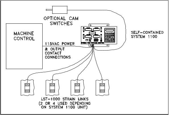
Figures 1 and 2 show the components that are contained in the System 1100 for the self-contained and the panel-mount versions respectively.
The self-contained unit (Figure 1) houses all the electronics of the System 1100 Tonnage Monitor. External connections are required only for strain links, press control stop circuit, and optional rotary cam switches.
1-3
INTRODUCTION
___________________________________________________________________
Figure 1. System Components of Self-contained System 1100.
The panel-mount unit (Figure 2) separates the Operator Interface Terminal electronics from the Logic Unit electronics. This configuration is useful when the tonnage monitor display is to be mounted in a panel where depth is limited, or when the display is to be mounted a long distance from the strain gauges.
1-4

INTRODUCTION
___________________________________________________________________
Figure 2. System Components for Panel-mount System 1100.
1-5

Section 2. Operation
2.1The Operator Interface
The operator interface is the means by which the operator can control the operation of the System 1100. The following features of the Operator Interface will be referred to extensively in this manual and so the operator should be familiar with them. A picture of the Operator Interface is located on the last page of this manual and can be folded out for viewing.
1)Tonnage Displays. The tonnage displays are large 4-digit red LED displays used to display peak tonnage.
2)Tonnage Bar-graphs. The tonnage bar graphs are ten segment multi-colored LED displays used to show peak tonnage relative to the HIGH and LOW setpoints and to indicate high and low alarms.
3)Mode Selector Keyswitch. The mode selector keyswitch is used to control the operating mode of the System 1100 and to gain access to tonnage setpoint limits and configuration data.
4)Indicator LEDs. The three indicator LEDs are used to indicate Auto Setup mode, Low Limits Off, and an active Stop Circuit.
5)LCD Display. The 2 line by 20 character LCD display is used to display messages and access the menus of the System 1100.
6)Keyboard consisting of 25 keys. The keyboard is used to enter setpoints, configuration data, clear alarms, and for all other operator input that is required.
2.1.1Tonnage Displays and Bar Graphs
The tonnage displays are used to display the peak forward and reverse tonnage measured by the System 1100. Selection of forward or reverse peak tonnage for display is discussed in the next section.
The bar graphs are used to graphically display the measured forward tonnage relative to the high and low setpoints. The top segment on the bar graph represents the high setpoint, and the bottom segment
2-1
OPERATION
___________________________________________________________________
the low setpoint. The segment representing the measured tonnage relative to the high and low setpoints is lighted each time a new tonnage is displayed.
2.1.1.1Display of Alarms
Alarms are generated when the System 1100 detects that the measured tonnage has exceeded a preset value (high setpoint, reverse setpoint, or machine rating) or in the case of low setpoints, has not exceeded a minimum value. Alarms are indicated on the System 1100 using the tonnage displays and the bar graphs.
Machine rating alarms are generated when the measured tonnage exceeds 125% of the channel rating, where the channel rating is the machine rating divided by the number of channels. Machine rating alarms are indicated by a flashing tonnage display on the channel on which the alarm occurred.
High setpoint alarms are generated when the measured tonnage for a channel meets or exceeds the high setpoint for that channel. High setpoint alarms are indicated by the top red segment on the channel bar graph flashing.
Low setpoint alarms are generated when the measured tonnage for a channel during the stroke does not meet or exceed the low setpoint. Low setpoint alarms are indicated by the bottom red segment on the channel bar graph flashing.
Reverse setpoint alarms are generated when the reverse tonnage for a channel meets or exceeds the reverse setpoint for that channel. Reverse setpoints alarms are indicated by a flashing reverse tonnage (reverse tonnages are indicated by a minus sign in the tonnage display).
2.1.2Keyboard Use
The upper left portion of the System 1100 keyboard is the numeric keypad. The numeric keypad is used for entering setpoints, configuration data, and other numeric data. The remaining keys have special functions that are explained in the remainder of this section.
2.1.2.1AUTO SETUP key
The AUTO SETUP key is used to access the Automatic Setup function
2-2

OPERATION
___________________________________________________________________
of the System 1100. The operator must be in the Main menu and have the keyswitch in the PROG position to access this function.
Automatic setup stores the highest and lowest peak tonnage from sixteen successive strokes. High setpoints are calculated as the highest peak tonnage plus a user selected percentage of channel rating (the auto setup tolerance), low setpoints are the lowest peak tonnage minus the auto setup tolerance, and reverse setpoints are the highest reverse reading plus the auto setup tolerance. Automatic setup sets all setpoints, high, low, and reverse, for the peak and for all data windows (if used).
When Automatic Setup is begun by the operator, the AUTO SETUP indicator will turn on and the automatic setup screen will appear as shown below.
AUTO SETUP TOL: 5%
STROKES NEEDED: 16
While the keyswitch is in the PROG position, the automatic setup tolerance will flash, indicating that it can be changed. The tolerance can be adjusted up to 30% or down to 1% using the up and down arrow keys respectively.
The number of STROKES NEEDED will count down as the operator cycles the machine. When all sixteen strokes have been made the System 1100 will calculate and store all setpoints. The AUTO SETUP light will then go out, and the Main menu will again appear. The setpoints are stored in the current setup just as if they had been entered manually.
The automatic setup procedure can be aborted at any time before the sixteenth stroke by pressing the CLEAR key or the EXIT key. The previously entered setpoints will then remain in effect.
WARNING! While in Automatic Setup Mode (when AUTO SETUP light is on) the System 1100 is effectively BYPASSED. All high, low, and reverse alarms are turned OFF. Only machine rating alarms are active.
2.1.2.2 LOW LIMIT ON/OFF key
2-3
OPERATION
___________________________________________________________________
The LOW LIMIT ON/OFF key is used to switch the low setpoint limits on or off. This functions is accessible only while the keyswitch is in the PROG position.
2.1.2.3DOWN TIME CODE key
The DOWN TIME CODE key is for use with the Link System Tonnage Monitor local area network system and is not used at this time.
2.1.2.4TONNAGE FORWARD/REVERSE key
The TONNAGE FORWARD/REVERSE key is used to switch the tonnage displays between forward and reverse tonnage. When reverse tonnage is selected a minus sign will appear at the left of each tonnage display, when forward tonnage is selected the minus sign will go out.
2.1.2.5HELP key
The operator may request a Help screen from the System 1100 by pressing the HELP key. The Help screens are intended to aid the operator by giving additional information and explanation of the current stage of the program sequence. Some Help screens may be more than two lines long. If the last character on the screen is a down arrow, more help information is available. The operator can press the down arrow key to view the additional lines. The operator can terminate a help screen and return to the program at any time by pressing the EXIT key . If no help screen is available for the present program sequence, a message will inform the operator that a help screen is not available.
2.1.2.6CLEAR key
The CLEAR key is used for two main functions. The first function is to remove any data input in progress. If the operator keys in the wrong data but has not yet pressed the ENTER key, he may press the CLEAR key to remove the entire data input. The correct data may then be keyed in. The CLEAR key cannot remove any data once it has been entered with the ENTER key.
The second function of the CLEAR key is to clear stops, alarms and errors. If a counter reaches its programmed limit and stops the machine, the CLEAR key can be pressed to reset the counter and allow the machine to be restarted. If an alarm is present, such as channel 3 high setpoint alarm, or and error is present, such as
2-4

OPERATION
___________________________________________________________________
ERROR 40 - End Of Cycle cam failure, the CLEAR key can be pressed to clear the alarm or error.
2.1.2.7 CONTRAST key
The CONTRAST key is used to adjust the contrast of the LCD  display. The display can be adjusted brighter or dimmer by holding down the CONTRAST key then pressing the up or down arrow keys respectively. If the keys are held down this function will automatically repeat to avoid having to repeatedly press the keys for large adjustments.
2.1.2.8HIGH SET and LOW SET keys
The HIGH SET and LOW SET keys are used to display the high and low setpoints on the tonnage displays. The setpoints will be displayed as long as the key remains depressed.
2.1.3Mode Selector Keyswitch
The Mode Selector Keyswitch is a three position keyswitch. The key can only be removed in the RUN position.
RUN - This is the normal operating mode of the System 1100. When the key is in this position, the operator can only view setpoint limits, and counter information. Tonnage setpoint limits and counter limits and count values cannot be altered or cleared.
PROG - This is the program mode of the System 1100. When the key is in this position, tonnage setpoint limits can be changed or turned off, setups can be stored, recalled or removed, and counter limits can be changed, turned off, and count values cleared.
BYPASS - This mode is While in Bypass mode alarms are turned OFF. while in bypass mode.
intended for use while die setting. all high, low, and reverse setpoint Only machine rating alarms are active
2.2Menu Selection
The LCD (Liquid crystal display, at the right-top of the operator
2-5

OPERATION
___________________________________________________________________
interface) provides the operator with information needed to program the System 1100. This is done by displaying a menu (list of choices) and allowing the operator to select one of the menu items. The blinking pointer is called the cursor and is used to identify which item on the list is currently selected. The cursor can be moved to a different choice on the menu using the up and down arrow keys (see the figure on the foldout in the back of the manual). Once the cursor is on the item desired, the operator can press the ENTER key to get further information about that item. The operator is not required to memorize any function names or keyboard entry sequences.
2.2.1Main Menu
The Main menu is the first list of options offered to the operator during programming of the System 1100. The Main menu contains six functions from which to choose. The Main menu is shown below.
MAIN $DISPLAY |
$ |
MENU $SETPOINTS |
$9 |
STO/RCL |
|
COUNTERS |
|
ERRORS |
|
CONFIG |
|
Only two menu options can be shown at one time on the LCD display; the remaining options are accessible by using the up and down arrow keys. If options are available either above or below the currently displayed menu options, then up or down arrows will appear on the right side of the menu indicating so.
To select an option from the menu list, move the cursor to the desired option using the up and down arrow keys then press the ENTER key.
Note that if data windows are disabled in the Config menu the DISPLAY option will not appear in the Main menu.
2.3Tonnage DISPLAY Selection
If the System 1100 has been configured for use with data windows
2-6

OPERATION
___________________________________________________________________
(section 2.8.6), the DISPLAY option will appear as the first selection in the Main menu. The Tonnage Display menu, simply called 'DISPLAY' in the Main menu, is used to select which tonnage reading will appear on the tonnage displays. The Tonnage Display menu is shown below.
TONNAGE$ PEAK $
DISPLAY$ TONNAGE $9
DATA
WINDOW 1
DATA
WINDOW 2
DATA
WINDOW 3
DATA
WINDOW 4
The up and down arrow keys are used to select the desired tonnage for display. When the desired tonnage is shown on the menu the corresponding tonnage readings will be displayed on the tonnage displays.
Exiting the Tonnage Display menu automatically switches the tonnage displays back to the peak tonnage. The Tonnage Display menu can be exited by pressing the EXIT key or the CLEAR key.
2.4SETPOINTS
If the System 1100 has been configured for use with data windows (section 2.8.6), the Setpoints menu will appear when the SETPOINTS option is selected from the Main menu, if the System 1100 has not been configured for use with data windows, the screen shown in section 2.4.1 will appear.
The Setpoints menu (shown below) allows the user to select a group of setpoints for viewing or editing and to turn on or off the use of individual data windows.
2-7

OPERATION
___________________________________________________________________
SETPTS$PEAK |
$ |
|
MENU $DW1 (ON) |
$9 |
|
DW2 (ON) |
|
|
DW3 |
(OFF) |
|
DW4 |
(OFF) |
|
To view or edit a group of setpoints, select the desired group using the up and down arrow keys, then press the ENTER key. Setpoints for data windows that are turned OFF cannot be viewed or edited until they are turned ON.
To turn on or off the use of a data window, first move the keyswitch to the PROG position. Next, select the desired data window using the up and down arrow keys, then press either the ON or OFF key.
2.4.1Editing Setpoints
The Setpoints Editing screen allow the operator to view and edit a group of setpoints. A group of setpoints consists of a high, low, and reverse setpoint for each channel. A typical setpoints editing screen for a four channel System 1100 is shown below.
HI-SET LO-SET |
18.2 |
|
REV-SET (ON) |
|
CH1 |
22.0 |
96 |
2.0 |
|
CH2 |
21.7 |
17.9 |
|
2.1 |
CH3 |
21.9 |
18.1 |
|
2.0 |
CH4 |
21.1 |
17.3 |
|
2.2 |
Because of the limited size of the LCD display, not all setpoints can be shown at one time. When additional setpoints are located either above, below, right, or left of the displayed setpoints, arrows indicating so will appear on the right side of the screen.
While the keyswitch is in the BYPASS or RUN positions the operator can only view the tonnage setpoint limits. When the keyswitch is in the PROG position the currently selected setpoint limit will flash indicating that it can be changed. To change a setpoint, first select it using the up, down, left, and right arrow keys,
2-8

OPERATION
___________________________________________________________________
then enter the new setpoint over the old using the numeric keypad. When finished entering the setpoint, press the ENTER key.
The group of setpoints shown above is for the absolute peak tonnage. Data window setpoint groups are indicated as shown below with the data window number appearing in the upper left corner of the setpoints editing screen.
DW2 HI-SET LO-SET |
|
REV-SET (ON) |
||
CH1 |
11.3 |
9.3 |
96 |
.4 |
CH2 |
11.3 |
9.2 |
|
.4 |
CH3 |
10.9 |
9.1 |
|
.4 |
CH4 |
11.2 |
9.2 |
|
.4 |
The following rules apply to setpoint limits:
1)High setpoints cannot exceed 125% of channel rating. (channel rating = machine rating/number of channels)
2)A Low setpoint must be lower than the channel's high setpoint.
3)Reverse setpoints cannot exceed 125% of channel rating.
2.4.1.1Turning Reverse Setpoints ON/OFF
Reverse setpoints can be enabled or disabled in the setpoints editing screen by selecting any reverse setpoint using the cursor keys, then pressing either the ON or OFF key. This will enable or disable ALL reverse setpoints (peak and all data windows). Enabling and disabling of reverse setpoints can only be done while the keyswitch is in the PROG position.
2.5STO/RCL
In the System 1100, the information which includes all peak and data window tonnage setpoint limits is called the current setup. Since tonnage setpoints limits are set according to the tonnage required to make a good part for a particular die, and they must usually be changed each time the die is changed. Ordinarily this would require either manually entering new setpoints or executing
2-9
OPERATION
___________________________________________________________________
the automatic setup function. Manually entering large numbers of setpoints can be tedious, and using automatic setup each time a die is changed gives no indication of what tonnage the die operated at the last time it was used. What is needed is a permanent record of the required tonnage for each die. The System 1100 provides for permanent storage of up to 123 different setups through the Sto/Rcl menu. The Sto/Rcl menu is shown below.
STORCL$STORE |
$ |
MENU $RECALL |
$9 |
REMOVE |
|
The Sto/Rcl menu provides the operator with the capability to store setups to backup memory, recall setups from backup memory, and erase setups from backup memory.
2.5.1STORE
The Store menu allows the operator to assign a job number and description to the current setup, and to save the current setup to backup memory. The Store menu is shown below.
STORE $ENTER JOB# $
MENU $ENTER DESC.$9
STORE JOB
2.5.1.1ENTER JOB#
The ENTER JOB# screen allows the operator to assign a six digit job number to the current setup. When the ENTER JOB# screen is entered, the job number of the current setup is displayed as shown below.
ENTER JOB NUMBER: 000025
While the keyswitch is in the PROG position, the job number will flash indicating that it can be changed. To change the job number
2-10

OPERATION
___________________________________________________________________
enter the new number over the old using the numeric keypad, then press the ENTER key.
2.5.1.2ENTER DESC
The ENTER DESC screen allows the operator to assign a 16 character description to the current setup. When the ENTER DESC screen is entered, the description of the current setup is displayed as shown below.
ENTER JOB DESC: (LATCH01 )
While the keyswitch is in the PROG position, the description will flash indicating that it can be changed. To change the description, enter the new description over the old using the numeric keypad for numbers and the up and down arrow keys for letters. When selecting letters with the up and down arrow keys, once the desired letter is selected use the right arrow key to move to the next letter in the description. When finished entering the description press the ENTER key.
2.5.1.3STORE JOB
Once the job number and description have been set, the setup should be stored to backup memory. When the STORE JOB option is selected from the Store menu the screen below will be displayed.
STORE (YES/NO) ? 000025
To store the job to backup memory press the YES key, to abort this operation press the NO key or the EXIT key. If a setup is already stored in backup memory with the same job number, the screen below will appear.
JOB FOUND IN MEMORY.
OVERWRITE (YES/NO) ?
2-11

OPERATION
___________________________________________________________________
To store the current setup over the setup already in backup memory press the YES key, otherwise press the NO key or the EXIT key.
Figure 4. Storing a Setup.
At the conclusion of a successful job storage operation, the screen below will be displayed.
JOB STORAGE DONE.
PRESS EXIT.
NOTE: Although setups are stored in the System 1100 the operator is encouraged to keep written records of stored setups. These records will be useful in recovering setups accidently lost by operator error or in the event of memory failure within the System 1100.
2.5.2RECALL
The Recall menu allows the user to recall previously stored setups from backup memory into the current setup. The Recall menu is shown below.
RECALL$ENTER JOB# $
MENU $SELECT JOB $9
2-12

OPERATION
___________________________________________________________________
2.5.2.2ENTER JOB#
The ENTER JOB# screen allows the operator to directly enter the number of job to recall. The ENTER JOB# screen is shown below.
ENTER JOB NUMBER TO
RECALL: ______
The six digit job number is entered by the operator using the numeric keypad. When the operator presses the ENTER key after keying in the job number, the System 1100 searches the backup memory for the requested job and recalls it if it is found. If the requested job is not present in backup memory a message indicating so will be displayed.
2.5.2.1SELECT JOB
The SELECT JOB screen allows the operator to search through a list of all jobs stored in backup memory and select from that list a job to recall. A typical SELECT JOB screen and list of jobs is shown below.
The operator can use the up and down arrow keys to move through the list of jobs. When the operator presses the ENTER key the System 1100 recalls the job currently shown on the LCD display.
JOB NUMBER: 000001 |
|
|
(X32-0786 |
) |
9 |
JOB NUMBER: 000012 (Q45-REV01 )
JOB NUMBER: 000003 (HUB-CAP )
JOB NUMBER: 000025 (LATCH01 )
2-13

OPERATION
___________________________________________________________________
Figure 5. Recalling a Setup.
2.5.3REMOVE
The Remove menu allows the user to erase stored job setups from backup memory. The Remove menu is shown below.
REMOVE$ENTER JOB# $
MENU $SELECT JOB $9
2.5.3.1ENTER JOB#
The ENTER JOB# screen allows the operator to directly enter the number of the job to remove from backup memory. The ENTER JOB# screen is shown below.
ENTER JOB NUMBER TO
REMOVE: ______
The six digit job number is entered by the operator using the
2-14

OPERATION
___________________________________________________________________
numeric keypad. When the operator presses the ENTER key the System 1100 searches backup memory for the requested job and erases it if it is found. If the requested job is not found a message indicating so will be displayed.
2.5.3.2SELECT JOB
The SELECT JOB screen allows the user to search through a list of all jobs stored in backup memory and select a job for removing. A typical SELECT JOB screen and list of jobs is shown below.
JOB NUMBER: 000001 |
|
|
(X32-0786 |
) |
9 |
JOB NUMBER: 000012 (Q45-REV01 )
JOB NUMBER: 000003 (HUB-CAP )
JOB NUMBER: 000025 (LATCH01 )
The operator can use the up and down arrow keys to move through the list of jobs. When the operator presses the ENTER key the System 1100 erases from backup memory the job currently displayed on the LCD display.
2.6COUNTERS
The Counters menu provides access to the eight counters of the System 1100. The counters can be divided into three types, counters with presettable limits, alarm counters, and the Stroke counter. Counters with presettable limits include the Part, Batch, and Quality counters. Alarm counters include Machine Rating Alarms, High Setpoints Alarms, Low Setpoint Alarms, and the Reverse Setpoint Alarms counters.
When the Rate of Change automatic zeroing method is used (section 3.5.1) spurious counts can be produced if clutch or brake engagement produces forces in the machine frame greater than the
2-15

OPERATION
___________________________________________________________________
zeroing threshold. The most accurate counts can be obtained when the System 1100 is used with the optional zeroing cam (sections 2.8.5 and 3.5.2).
The Counters menu is shown below.
CNTRS |
$PART |
$ |
MENU |
$BATCH |
$9 |
QUALITY
M.R. ALARM
HIGH ALARM
LOW ALARM
REV. ALARM
STROKE
2.6.1PART, BATCH, and QUALITY COUNTERS
The Part, Batch, and Quality counters have presettable limits. These counters can be programmed to stop the production process after a specified number of parts have been made. Only good parts are counted, that is, parts whose forward tonnage is between the high and low setpoints, and whose reverse tonnage is less than the reverse setpoint. These counters operate in this way regardless of BYPASS mode, or low or reverse limits being turned off.
For installations where the System 1100 stop circuit is connected to the emergency stop of the press control, the System 1100 provides a top-stop delay timer (section 2.8.9). This timer is capable of providing delays from 0 to 1 seconds to stop the machine with the ram at the top of the stroke when a counter limit is reached.
The Part counter is intended to count the total number of parts in a run. The Batch counter is intended to count the number of parts per batch. This counter is useful if part bins must be changed several times during a part run. The Quality counter is used to stop the production process at regular intervals for the operator to perform part quality inspections.
The Part, Batch, and Quality counters all operate similarly and so the examples discussed below apply to all of these counters. An example Batch counter screen is shown below.
2-16

OPERATION
___________________________________________________________________
BATCH CNT: 0012934 (ON) LIMIT: 0123000
While the keyswitch is in the PROG position, the counter limit will flash, indicating that it can be changed. This is done by entering the new limit over the old using the numeric keypad, and then pressing the ENTER key. The counter can be turned on or off while in PROG mode by pressing the ON or OFF keys respectively. The count value can be reset to zero while in PROG mode by pressing the CLEAR key. The screen below will then appear.
CLEAR COUNTER? (YES/NO)
Pressing the NO key will leave the count value in tact, while pressing the YES key will reset the counter to zero. The example counter screen is shown below after the counter has been cleared.
BATCH CNT: 0000000 (ON) LIMIT: 0123000
2.6.2MACHINE RATING, HIGH, LOW and REVERSE ALARMS COUNTERS
The MACHINE RATING, HIGH, LOW, and REVERSE alarms counters count the number of occurrences of each type of alarm. These counters do not have limits, but should be checked regularly for excessive numbers of alarms. All alarm counters operate similarly and so the following discussion applies to all the alarm counters. An example HIGH alarms counter screen is shown below.
HIGH-SET ALARMS: 0000027
While the keyswitch is in the PROG position alarm counters can be reset to zero by pressing the CLEAR key. The screen below will then prompt the operator for the access code.
2-17

OPERATION
___________________________________________________________________
ENTER ACCESS CODE:
____
The access code is entered by using the numeric keypad, then pressing the ENTER key. If the correct access code is entered, the screen below will then appear.
CLEAR COUNTER? (YES/NO)
Pressing the NO or EXIT keys will leave the alarm counter value in tact, while pressing the YES key will reset the alarm counter to zero. The alarm counter screen below is shown after the counter has been cleared.
HIGH-SET ALARMS: 0000000
2.6.3STROKE COUNTER
The stroke counter is used to record the total number of machine stokes since the System 1100 was installed on the machine. The stroke counter screen is shown below.
STROKE COUNT: 0000145267
The stroke counter can be cleared by pressing the CLEAR key and then entering a special access code. The stroke counter can be cleared only while the keyswitch is in the PROG position. Since the stroke counter is meant to count the total number of strokes for the machine, it should never be cleared except in the case of moving the System 1100 to a different machine.
2.7ERRORS
2-18

OPERATION
___________________________________________________________________
The Errors menu provides the operator with the capability to view a list of the currently active errors. Error codes are provided with a short plain English explanation of error.
An example list of errors is shown below.
ERROR 05 - Channel 1 above threshold.9
ERROR 01 - Channel
1 will not zero.
ERROR 40 - End Of
Cycle cam failure.
ERROR 48 - Chan 1 high set too high.
Only one error is displayed at a time, with other errors available by pressing the up and down arrow keys as indicated by the arrows appearing at the right of the error screen. Errors can be cleared by pressing the CLEAR key.
2.8CONFIG
The Config menu allows the operator to program important information about the machine on which the System 1100 is installed, and on how the System 1100 will operate.
When the CONFIG option is selected from the Main menu the operator will be prompted with the access code screen seen below.
ENTER ACCESS CODE:
____
The access code is entered by using the numeric keypad, then pressing the ENTER key. If the correct access code is entered, the Config menu will appear as shown below.
2-19
 Loading...