


OmniLink 5000

System 5000
Press Control
DIE PROTECTION
MODULE
OmniLink 5000
COLOR DISPLAY
OPERATING MANUAL
LINK ELECTRIC & SAFETY CONTROL COMPANY
444 McNALLY DRIVE, NASHVILLE TN 37211
PH (615)-833-4168 FAX (615)-834-1984

System 5000
Die Protection Module
Operator Manual
Manual LS-001
Revision 07

TABLE OF CONTENTS
Section 1 Introduction to the System 5000 Die Protection Module .................. 1-1
Section 1.1 Features ................................................... 1-1
Section 2 Operation ......................................................... 2-1
Section 2.1 Main Menu Status Block ...................................... 2-1
Section 2.2 Die Protection Menu ......................................... 2-1
Section 2.3 Access Control .............................................. 2-2
Section 2.3.1 Key Only Mode ...................................... 2-2
Section 2.3.2 Key or Password Mode ................................ 2-2
Section 2.3.3 Password Only Mode ................................. 2-3
Section 2.3.4 Key and Password Mode .............................. 2-3
Section 2.3.5 Die Protection Restricted Items ......................... 2-3
Section 2.3.6 Access Control Operation .............................. 2-4
Section 2.3.6.1 Program/Run Key Switch Operation ..............2-4
Section 2.3.6.2 Password System Operation .................... 2-4
Section 2.4 Type of Sensor .............................................. 2-6
Section 2.4.1 Programming Input Type ............................... 2-7
Section 2.5 Input Description ............................................ 2-7
Section 2.6 Input Status ................................................ 2-9
Section 2.7 Input State ................................................ 2-10
Section 2.8 RESET ERRORS key ....................................... 2-10
Section 2.9 BYPASS ON/OFF key ...................................... 2-10
Section 2.10 View Channel Information ................................... 2-11
Section 2.10.1 Changing Channel Information ........................ 2-11
Section 2.10.2 Programming Stop Output ........................... 2-12
Section 2.10.3 Programming Delay Time ............................ 2-12
Section 2.10.4 Programming Window Setpoints ......................2-13
Section 2.10.5 Programming Separation Time ........................ 2-13
Section 2.10.6 Programming Track Channel ......................... 2-13
Section 2.10.7 Programming Track Time ............................2-14
Section 2.11 Input Capture Capability .................................... 2-14
Section 2.12 Programmable Limit Switch Menu ............................ 2-15
Section 2.13 Job Setups ............................................... 2-16
Section 3 Die Protection Input Types and Their Uses ............................. 3-1
Section 3.1 Static N.O. and Static N.C. .................................... 3-1
Section 3.2 Cyclic .....................................................3-2
Section 3.3 Transfer ................................................... 3-3
Section 3.4 In Position ................................................. 3-4
Section 3.5 1 Part Detector-Edge and 1 Part Detector-Pass ..................... 3-5
i

Section 3.6 2 Part Detector-Edge and 2 Part Detector-Pass ..................... 3-6
Section 3.7 Track PLS and Track PLS Invert ................................3-7
Section 4 Installation ....................................................... 4-1
Section 4.1 Extended Card Rack ......................................... 4-1
Section 4.2 Module Installation .......................................... 4-1
Section 4.3 Machine Parameters Configuration .............................. 4-1
Section 4.4 Wiring .................................................... 4-2
Section 5 Troubleshooting ................................................... 5-1
Section 5.1 Status Messages ............................................. 5-1
Section 5.1.1 Main Menu Status Messages ........................... 5-1
Section 5.1.2 View Channel Status Messages ......................... 5-2
Section 5.1.2.1 Static Messages .................................... 5-2
Section 5.1.2.2 Cyclic Messages .................................... 5-2
Section 5.1.2.3 Transfer Messages ............................ 5-3
Section 5.1.2.5 1 Part Detector Messages .......................5-4
Section 5.1.2.6 2 Part Detector Messages .......................5-4
Section 5.1.2.7 Track PLS Messages .......................... 5-5
Section 5.1.2.8 Track PLS Invert Messages .....................5-6
Section 5.1.2.9 General Status Messages ....................... 5-6
Section 5.2 Diagnostic LEDs ............................................ 5-7
ii

Section 1 Introduction to the System 5000 Die Protection Module
The Die Protection Module is an optional addition to the integrated System 5000 Press Control
which is designed for use in monitoring various die conditions that are important to the correct
operation of the die. This is accomplished by installing appropriate sensors and probes in or near
the die and connecting these sensors to inputs on the Die Protection Module. The inputs are then
programmed through the OmniLink Operator Terminal to perform the desired monitoring function.
In the event that improper conditions occur the machine can be then be stopped, avoiding excessive
delay in the production process or damage to the die.
The Die Protection Module consists of a circuit card which is installed in the System 5000 card rack
and a connector card assembly which interfaces the circuit card to the external sensors.
Section 1.1 Features
The Die Protection Module has 16 inputs available to the operator for use with die sensors and
probes. These inputs may be used to monitor part ejection, stock in place, material in position, stock
buckling, end of stock, or other functions of interest.
Each die protection input can be programmed as any of the following types: Static, Cyclic, Transfer,
In Position, Single Part detection, Two Part detection, or Track PLS. For each input programmed
as Cyclic, Transfer, In Position, or Part Detector types, the operator can assign to the input its own
timing sequence.
The operator can select an output of either Cycle Stop (immediate stop) or Top Stop for each die
protection input monitored.
Each time the operator stores a job setup through the System 5000 Press Control, all programmed
die protection data is also stored by the system. Similarly, when the operator recalls a job setup from
backup memory all die protection data is recalled and becomes effective immediately. The module
can store a total of 105 job setups (corresponding to the setups stored in the press control).
1-1

Section 2 Operation
Section 2.1 Main Menu Status Block
When the Main Menu is displayed on the System 5000 Operator Terminal, one of the softkeys on
the right side of the screen is labeled DIE PROTECTION. To the left of this key is a status block
indicating the current operating status of the die protection module. Under normal operating
conditions the status message will read "All Conditions OK". If the status message reads "Error
Condition Exists" then a failure has been detected on one of the die protection inputs or a fault exists
internal to the module itself. When this is the case the operator must go to the Die Protection Menu
to reset the error or proceed to view the error message. If the status message reads "Communication
Failure" then a problem exists in the serial communication link between the operator terminal and
the die protection module (see “Main Menu Status Messages” in Section 5). If the status message
reads "Option is NOT Installed", the system may not be configured for die protection. (Refer to
“Memory Configuration Requirements” in Section 4 for further details).
Section 2.2 Die Protection Menu
By pressing the DIE PROTECT softkey on the Main Menu, the LCD screen will display the Die
Protection Menu (see Figure 2.1). The label "Die Protection” is displayed above the softkeys in the
upper right corner. The softkeys available from this screen are labeled CAPTURE INPUTS, LIMIT
SWITCH, RESET ERRORS, and EXIT. When the user has obtained access control other softkeys
that may appear are CHANGE TYPE, CHANGE SETTINGS, CHANGE NAME, and BYPASS
ON/OFF. (Softkeys that appear when access control has been obtained are shown as highlighted in
Figure 2.1). The function of these keys is described in the sections following. Access control is
explained in Section 2.3. On this screen as on all others, the top of the screen is used for displaying
crankshaft angle, crankshaft speed, and the present stroke mode. The remainder of the screen is used
for displaying specific information about the die protection inputs.
2-1
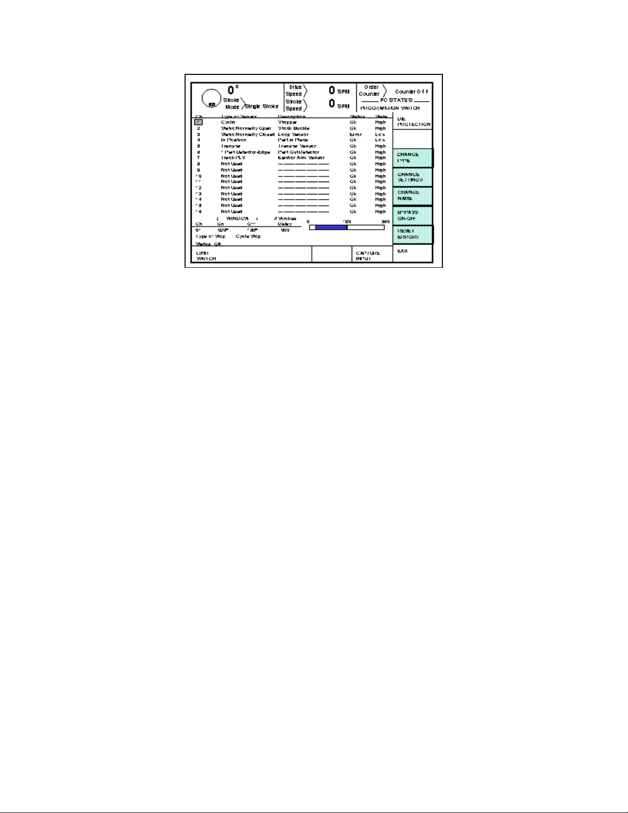
Figure 2.1 Die Protection Menu
Section 2.3 Access Control
The OmniLink control has several parameters or operations that have limited access. In regards to
die protection the ability to perform actions of turning bypass off and on, resetting faults, or
changing die protection settings must be restricted to certain personnel. The OmniLink control
provides several means to limit access to these parameters or operations. These parameters and
operations are called restricted items.
The OmniLink control employs combinations of two different means to limit access to restricted
items. These means are the Program/Run key switch and a user password system. The user
password system assigns names and passwords to up to sixteen users. These two means can be used
alone or in combination with each other. When a user employs the proper means to gain access
control, he will have the ability to perform the actions and change the parameters which have been
designated to his access.
There are four possible modes of operation for the restricted access system. They are the “Key
Only” mode, the “Key or Password” mode, the “Password Only” mode, and the “Key and Password”
mode. The control can be configured to operate in any one of these four modes.
Section 2.3.1 Key Only Mode
The “Key Only” mode is the least complex of the four modes. This mode employs the Program/Run
key as the only means to limit access to restricted items. Any user with the Program/Run key can
access all of the restricted items. Without the Program/Run key, user access to all of the restricted
items is prohibited.
Although the “Key Only” mode has the advantage of being easy to use, it does have a disadvantage.
This mode cannot give a particular user access to only some of the restricted items. When operating
2-2

in this mode, any user with the Program/Run key will have access to all of the restricted items.
Section 2.3.2 Key or Password Mode
The key or password mode allows for either of two means to gain access to the restricted items. A
user with Program/Run key can access all of the restricted items. A user with the correct password
can access the restricted items that have been designated for the particular user’s access only. The
system allows for passwords to be assigned to sixteen users. Each user can be assigned access to
any or all of the restricted items.
The following is an example of a “Key or Password” mode operation. The Program/Run key is
given to the die set-up personnel. A press operator is assigned a user name and password. With the
password the operator can reset die protection faults. This is the only die protection related item
to which the operator has access. In order to load a die, the set-up personnel uses the Program/Run
key to recall a job from job storage. The set-up personnel will also be able to make changes to die
protection settings. Once the set-up personnel sets the die and verifies its correct operation, the
operator is left to run the die. If a die protection fault occurs, the operator can enter the correct
password and then reset the fault. However, the operator cannot change die protection settings or
bypass the die protection. This will allow the operator to keep running the job and reset faults that
occur. However, if consistent stops occur because a die protection setting needs changing, the set-up
personnel must be called to change the die protection setting.
The example above can be taken one additional step, if two press operators are given different user
names and different passwords. One operator can be assigned the ability to change die protection
settings in addition to the ability to reset die protection faults, while the other operator is not
assigned the ability to change the die protection settings.
Section 2.3.3 Password Only Mode
The “Password Only” mode allows for sixteen users. Each user can be assigned access to some or
all of the restricted items. This mode does not use the Program/Run key.
The example listed above indicated that setup personnel required access to all restricted items. In
the “Key or Password” mode, the setup personnel used the Program/Run key to gain access to all
of the restricted items. In the “Password Only” mode, the setup personnel can still have access to
all of the restricted items, but the system must be configured as such. The setup personnel must be
assigned a user name and password. In addition, all restricted items would be assigned access to the
setup personnel.
Section 2.3.4 Key and Password Mode
The “Key and Password” mode requires the user to have the Program/Run key, user name, and user
password. Operation is basically the same as the Password only mode, except that in addition to
2-3

entering the password the user must switch the Program/Run key to the PROG position.
Section 2.3.5 Die Protection Restricted Items
The following table lists the die protection restricted items name and function.
DIE PROTECTION RESTRICTED ITEMS
NAME FUNCTION
DP Bypass Bypass the Die Protection
DP Reset Reset the Die Protection
DP Settings Change the Die Protection type, settings, and name.
Section 2.3.6 Access Control Operation
To gain access control the user must use one of two means or a combination of these two means.
These means are the Program/Run key or the user password system.
Section 2.3.6.1 Program/Run Key Switch Operation
The Program/Run key switch is located on the lower right side of the operator terminal. This is a
two position switch. The key is removable in the RUN position only. If the Program/Run key
switch is being used as a means to access the restricted items, the switch must be turned to the PROG
position. When the Program/Run key switch is switched to the PROG position, the press will Top
Stop and stroking will be prohibited until the switch is returned to the RUN position.
When operating in the Key Only mode the key switch is the only means available to access the
restricted items. All restricted items are accessible when the Program/Run key switch is switched
to the PROG position.
When operating in the “Key or Password” mode, the key switch is one of the means available to
access the restricted items. All restricted items are accessible when the Program/Run key switch is
switched to the PROG position.
When operating in the “Key and Password” mode, the key switch and password must be used to
access the restricted items. In this mode, the user will be granted access only to the restricted items
that have been assigned to him.
When the Program/Run switch is in the Program position, the softkeys highlighted in Figure 2.1 will
2-4
appear and will be active.
Section 2.3.6.2 Password System Operation
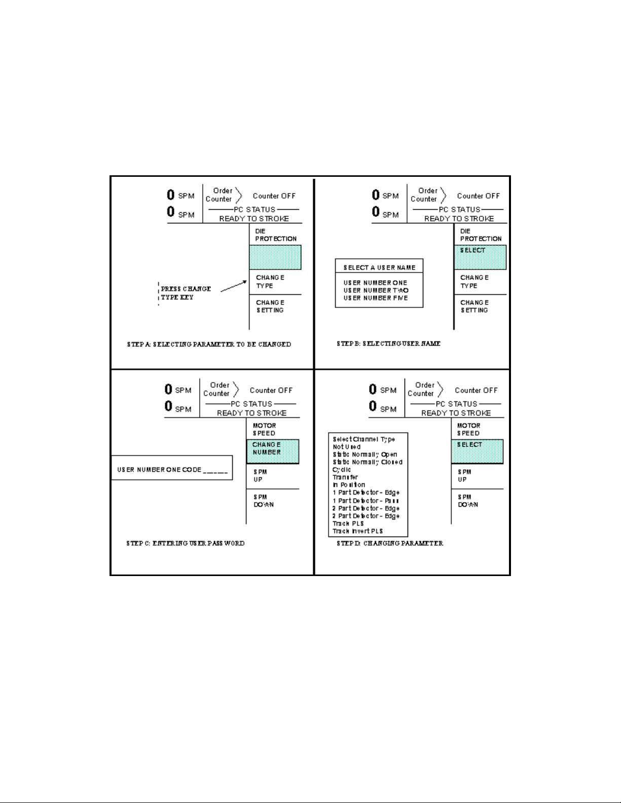
Figure 2.2 displays a typical password entry sequence. This example shows the steps necessary to
change a die protection channel setting. This is typical for password entry for all restricted items.
Figure 2.2 Password Entry Sequence
Step A: Select the restricted item. In the example shown in Figure 2.2 the restricted item is
die protection Change Type. Once the parameter is selected then Softkey # 1 the
upper vertical softkey (Softkey # 1 is highlighted in Figure 2.2) , will display the
legend “Select”.
Step B: A list of users that have access to this restricted item will appear. In the example
2-5

shown in Figure 2.2 only User Number One, User Number Two, and User Number
Five have access to this restricted parameter. The system may have several more
users, but the three users listed on the screen are the only users that have access to
change a die protection setting. The user must use the arrow keys to position the
cursor on his user name. After placing the cursor on the correct name, the user must
press the SELECT softkey. The SELECT softkey must be pressed even if there is
only one user name displayed.
Step C: The display will show the selected user name and request the user password. The
user must enter the correct password and then depress the ENT key.
Step D: Upon entry of the correct password, the user will be allow access to the restricted
item. the example shown in Figure 2.2, the user will have access to change the die
protection type.
After performing the steps listed above, the user will be logged in to the password system. The user
will have access to all restricted items that have been designated for his access. This access will
remain until the user performs a log out or until the user is automatically logged out.
The user can log out by using the ACC key. This key will directly switch the display to the Quick
Access screen. The LOGOUT soft key legend will appear along the bottom of the screen. If the
operator presses this key, he will log out. He will no longer have access to the restricted items,
unless he repeats steps A through D.
In addition to the manual log out, the system contains an automatic logout. The intent of automatic
log out is to reduce the possibility of users other than the intended user from having access to
restricted items. If there were no provisions for automatic log out and a user forgot to manually log
out, all restricted items to which the user had been designated for access would be available from
the log in time until power was removed from the OmniLink control. This presents the possibility
of users other than the intended user having access to restricted items. Automatic log out is based
upon both time and press strokes. During system configuration automatic Access Timeout
parameters are entered. An automatic access timeout time and automatic access timeout strokes are
entered. The time entered is the amount of time after the last key stroke that will be allowed before
the system will automatically log out the user. For example, if the automatic access timeout is set
to 60 seconds, the user will be logged out 60 seconds after the last key stroke. If the user depresses
a key before the 60 seconds have elapsed, a new 60 second cycle will be started. The number of
strokes that are entered is the number of press strokes after the last key stroke that will be allowed
before the system automatically logs out the user. For example, if the automatic timeout is set to 10
strokes, the user will be logged out when the press completes ten strokes after the last key stroke.
If the user depresses a key before 10 strokes have been completed, a new 10 stroke cycle will be
started.
Section 2.4 Type of Sensor
2-6

The Die Protection Menu displays the programmed types for the die protection input channels. The
channel numbers under the "CH" column on the left correspond to the input terminal numbers on
the connector card assembly for the die protection module.
For each of the inputs, the information under the "Type of Sensor" column describes how the input
is programmed to operate. This is determined in advance by the operator according to what
condition in the die the input is to monitor. The type determines, for example, whether the sensor
connected to an input should remain in a certain state at all times or whether it should switch open
and closed with each press stroke. If the input is to switch, the type also determines timing
restrictions within the stroke as to when and how the input must switch. For any input there are
eleven different program types from which to choose, or the operator may program the input as
Unused. (Several different input types are illustrated in the sample screen of Figure 2.1). More
information is provided for choosing the correct type for a die protection input in Section 3. Specific
information on how to program an input to be a certain type is given in Section 2 in the portion titled
“Programming Input Type”.
Section 2.4.1 Programming Input Type
The type of die protection input is programmed by the operator and specifies how the input is to
interpret the action of the sensor which is wired to its input terminal. There are eleven active Types
which can be chosen:
Static Normally Open
Static Normally Closed
Cyclic
Transfer
In Position
1 Part Detector (Edge Only or Pass Completely)
2 Part Detector (Edge Only or Pass Completely)
Track PLS
Track PLS Invert
Alternately, the input type can be programmed as Unused if the input is not to be used. Information
on how the different types operate and how they can be used in different applications is found in
Section 3. (Refer to Section 3 of this manual when determining how to set up sensors and program
their inputs to accomplish the desired die monitoring).
To select a die protection type, the user must first obtain access control. Access control is described
in Section 2.3. If the user obtains access control by using the password system, the user must be
configured to have access to change die protection settings. To begin the change type process, first
position the cursor to the channel that is to be changed. If operating in a keyed access mode, place
the Program/Run switch in the PROG position. This step is not required if operating in a password
access mode. Then press the CHANGE TYPE softkey. If operating in a password mode, access
2-7
 Loading...