


A Division of Cisco Systems, Inc.
®
2.4
Model No.
GHz
802.11g
WIRELESS
WRT54GS
Wireless-G
Broadband Router
with SpeedBooster
User Guide

Wireless-G Broadband Router with SpeedBooster
Copyright and Trademarks
Specifications are subject to change without notice. Linksys is a registered trademark or trademark of Cisco
Systems, Inc. and/or its affiliates in the U.S. and certain other countries. Copyright © 2004 Cisco Systems, Inc. All
rights reserved. Other brands and product names are trademarks or registered trademarks of their respective
holders.
How to Use This User Guide
This User Guide has been designed to make understanding networking with the Wireless-G Broadband Router
easier than ever. Look for the following items when reading this User Guide:
This checkmark means there is a note of interest and is
something you should pay special attention to while
using the Wireless-G Broadband Router.
This exclamation point means there is a caution or
warning and is something that could damage your
property or the Wireless-G Broadband Router.
This question mark provides you with a reminder about
something you might need to do while using the
Wireless-G Broadband Router.
In addition to these symbols, there are definitions for technical terms that are presented like this:
word: definition.
Also, each figure (diagram, screenshot, or other image) is provided with a figure number and description, like
this:
Figure 0-1: Sample Figure Description
Figure numbers and descriptions can also be found in the “List of Figures” section in the “Table of Contents”.
WRT54GS-UG-40217NC KL

Wireless-G Broadband Router with SpeedBooster
Table of Contents
Chapter 1: Introduction 1
Welcome 1
What’s in this Guide? 2
Chapter 2: Planning Your Wireless Network 4
Network Topology 4
Ad-Hoc versus Infrastructure Mode 4
Network Layout 4
Chapter 3: Getting to Know the Wireless-G Broadband Router 6
The Back Panel 6
The Front Panel 7
Chapter 4: Connecting the Wireless-G Broadband Router 8
Overview 8
Hardware Installation for Connection to Your Broadband Modem 8
Connecting One Router to Another 10
Chapter 5: Configuring the Wireless-G Broadband Router 13
Overview 13
The Setup Tab - Basic Setup 14
The Setup Tab - DDNS 18
The Setup Tab - MAC Address Clone 19
The Setup Tab - Advanced Routing 20
The Wireless Tab - Basic Wireless Settings 21
The Wireless Tab - Wireless Security 22
The Wireless Tab - Wireless MAC Filter 24
The Wireless Tab - Advanced Wireless Settings 25
The Security Tab - Firewall 27
The Security Tab - VPN Passthrough 27
The Access Restrictions Tab - Parental Control 28
The Access Restrictions Tab - Internet Access 29
The Applications and Gaming Tab - Port Range Forward 31
The Applications and Gaming Tab - DMZ 32
The Administration Tab - Management 33
The Administration Tab - Log 33

Wireless-G Broadband Router with SpeedBooster
The Administration Tab - Diagnostics 34
The Administration Tab - Factory Defaults 35
The Administration Tab - Firmware Upgrade 35
The Status Tab - Router 36
The Status Tab - Local Network 37
The Status Tab - Wireless 38
Chapter 6: Using the Linksys Parental Control Service 39
Overview 39
Introduction 39
Signing up for the Linksys Parental Control Service 40
Signing up for the Linksys Parental Control Service 41
Managing Linksys Parental Controls 44
Support Center 45
Activity Reports 47
Family Settings 49
Suggest a Rating 57
Using the Parental Control Service 57
Appendix A: Troubleshooting 60
Common Problems and Solutions 60
Frequently Asked Questions 69
Appendix B: Wireless Security 75
Security Precautions 75
Security Threats Facing Wireless Networks 75
Appendix C: Upgrading Firmware 78
Appendix D: Windows Help 79
Appendix E: Finding the MAC Address and IP Address for Your Ethernet Adapter 80
Windows 98SE or Me Instructions 80
Windows 2000 or XP Instructions 80
For the Router’s Web-based Utility 81
Appendix F: Glossary 82
Appendix G: Specifications 88
Appendix H: Warranty Information 90
Appendix I: Regulatory Information 91
Appendix J: Contact Information 93

Wireless-G Broadband Router with SpeedBooster
List of Figures
Figure 3-1: The Router’s Back Panel 6
Figure 3-2: The Router’s Front Panel 7
Figure 4-1: Connecting Your Modem 8
Figure 4-2: Connecting Your Network Devices 9
Figure 4-3: Connecting the Power 9
Figure 4-4: Connecting the Router Behind Another 10
Figure 4-5: Diagram for Connection to Another Router 10
Figure 4-6: The Router with the Internet Connection is connected through the Internet Port 11
Figure 4-7: Connecting Your Network Devices 11
Figure 4-8: Connecting the Power 12
Figure 5-1: Password Screen 13
Figure 5-2: Setup Tab - Basic Setup 14
Figure 5-3: DHCP Connection Type 14
Figure 5-4: Static IP Connection Type 14
Figure 5-5: PPPoE Connection Type 15
Figure 5-6: PPTP Connection Type 15
Figure 5-7: HeartBeat Signal Connection Type 16
Figure 5-8: Optional Settings 16
Figure 5-9: Router IP 17
Figure 5-10: Network Address Server Settings 17
Figure 5-11: Time Setting 17
Figure 5-12: Setup Tab - DDNS 18
Figure 5-13: Setup Tab - MAC Address Clone 19
Figure 5-14: Setup Tab - Advanced Routing (Gateway) 20
Figure 5-15: Setup Tab - Advanced Routing (Router) 20
Figure 5-16: Wireless Tab - Basic Wireless Settings 21
Figure 5-17: Wireless Tab - Wireless Security (WPA Pre-Shared Key) 22
Figure 5-18: Wireless Tab - Wireless Security (WPA RADIUS) 22
Figure 5-19: Wireless Tab - Wireless Security (RADIUS) 23
Figure 5-20: Wireless Tab - Wireless Security (WEP) 23

Wireless-G Broadband Router with SpeedBooster
Figure 5-21: Wireless Tab - Wireless MAC Filter 24
Figure 5-22: MAC Address Filter List 24
Figure 5-23: Wireless Tab - Advanced Wireless Settings 25
Figure 5-24: Security Tab - Firewall 27
Figure 5-25: Security Tab - VPN Passthrough 27
Figure 5-26: Access Restrictions Tab - Parental Control 28
Figure 5-27: Access Restrictions Tab - Internet Access 29
Figure 5-28: Internet Policy Summary 29
Figure 5-29: List of PCs 29
Figure 5-30: Port Services 30
Figure 5-31: Applications and Gaming Tab - Port Range Forward 31
Figure 5-32: Applications and Gaming Tab - DMZ 32
Figure 5-33: Administration Tab - Management 33
Figure 5-34: Administration Tab - Log 33
Figure 5-35: Administration Tab - Diagnostics 34
Figure 5-36: The Ping Test 34
Figure 5-37: The Traceroute Test 34
Figure 5-38: Administration Tab - Factory Defaults 35
Figure 5-39: Administration Tab - Firmware Upgrade 35
Figure 5-40: Status Tab - Router 36
Figure 5-41: Status Tab - Local Network 37
Figure 5-42: DHCP Clients Table 37
Figure 5-43: Status Tab - Wireless 38
Figure 6-1: Safe Surfing 40
Figure 6-2: Access Restrictions Tab - Parental Control 40
Figure 6-3: Linksys Service Agreement 41
Figure 6-4: Sign Up 41
Figure 6-5: Purchase Service 42
Figure 6-6: Connecting to the Parental Control Service 43
Figure 6-7: Congratulations 43
Figure 6-8: Parental Controls Login 44
Figure 6-9: Support Center 45
Figure 6-10: Subscribe to Service 45

Wireless-G Broadband Router with SpeedBooster
Figure 6-11: Update Contact Information 46
Figure 6-12: Cancel Your Parental Control Account 46
Figure 6-13: Activity Reports 47
Figure 6-14: Types of Reports 47
Figure 6-15: Web Report 48
Figure 6-16: Family Settings 49
Figure 6-17: New Family Member 49
Figure 6-18: All Settings 50
Figure 6-19: Online Reporting 50
Figure 6-20: Maturity Level 51
Figure 6-21: Time Restrictions 52
Figure 6-22: Web Browsing Restrictions 53
Figure 6-23: Web Site Categories 53
Figure 6-24: Blocked & Allowed Web Sites 54
Figure 6-25: E-mail Restrictions 55
Figure 6-26: E-mail Settings 55
Figure 6-27: Instant-Messaging Restrictions 56
Figure 6-28: Password 56
Figure 6-29: Suggest a Rating 57
Figure 6-30: Security Warning 57
Figure 6-31: Welcome to Parental Controls 58
Figure 6-32: Tray Icon 58
Figure 6-33: Pop-up Screen (Login) 58
Figure 6-34: Pop-up Screen (Sign Out) 59
Figure 6-35: Right-Click Tray Icon 59
Figure 6-36: Re-activate Tray Icon 59
Figure C-1: Upgrade Firmware 78
Figure E-1: IP Configuration Screen 80
Figure E-2: MAC Address/Adapter Address 80
Figure E-3: MAC Address/Physical Address 80
Figure E-4: MAC Address Filter List 81
Figure E-5: MAC Address Clone 81

Wireless-G Broadband Router with SpeedBooster
Chapter 1: Introduction
Welcome
Thank you for choosing the Linksys Wireless-G Broadband Router with SpeedBooster. The Wireless-G Broadband
Router with SpeedBooster will allow you to network wirelessly better than ever, sharing Internet access, files and
fun, easily and securely.
How does the Wireless-G Broadband Router with SpeedBooster do all of this? A router is a device that allows
access to an Internet connection over a network. With the Wireless-G Broadband Router with SpeedBooster, this
access can be shared over the four switched ports or via the wireless network, broadcast at either 11Mbps for
Wireless-B or 54Mbps for Wireless-G. In addition, WEP encryption provides greater security opportunities while
the whole network is protected through a Stateful Packet Inspection (SPI) firewall and NAT technology. All of
these security features, as well as full configurability, are accessed through the easy-to-use browser-based
utility.
But what does all of this mean?
Networks are useful tools for sharing computer resources. You can access one printer from different computers
and access data located on another computer's hard drive. Networks are even used for playing multiplayer video
games. So, networks are not only useful in homes and offices, they can also be fun.
PCs on a wired network create a Local Area Network. They are connected with Ethernet cables, which is why the
network is called “wired”.
PCs equipped with wireless cards or adapters can communicate without cumbersome cables. By sharing the
same wireless settings, within their transmission radius, they form a wireless network. The Wireless-G
Broadband Router with SpeedBooster bridges wireless networks of both 802.11b and 802.11g standards and
wired networks, allowing them to communicate with each other. And since this Router has SpeedBooster
technology, your wireless network performance increases by up to 30% from old 802.11g standards. In fact, even
non-SpeedBooster-equipped devices on your network will see a speed improvement when communicating with
SpeedBooster-enhanced equipment!
With your networks all connected, wired, wireless, and the Internet, you can now share files and Internet
access—and even play games. All the while, the Wireless-G Broadband Router with SpeedBooster protects your
networks from unauthorized and unwelcome users.
mbps: one million bits per second; a unit of
measurement for data transmission
browser: an application program that
provides a way to look at and interact with all
the information on the World Wide Web.
lan (Local Area Network): The
computers and networking products
that make up the network in your home
or office
802.11b: an IEEE wireless networking standard
that specifies a maximum data transfer rate of
11Mbps and an operating frequency of 2.4GHz.
802.11b: an IEEE wireless networking standard
that specifies a maximum data transfer rate of
54Mbps, an operating frequency of 2.4GHz, and
backward compatibility with 802.11b devices.
You should always use the Setup CD-ROM when you first install the Router. If you do not wish to run the Setup
Wizard on the Setup CD-ROM, then use the instructions in this Guide to help you connect the Wireless-G
Broadband Router with SpeedBooster, set it up, and configure it to bridge your different networks. These
instructions should be all you need to get the most out of the Wireless-G Broadband Router with SpeedBooster.
Chapter 1: Introduction
Welcome
1

Wireless-G Broadband Router with SpeedBooster
What’s in this Guide?
This user guide covers the steps for setting up and using the Wireless-G Broadband Router with SpeedBooster.
• Chapter 1: Introduction
This chapter describes the Router’s applications and this User Guide.
• Chapter 2: Planning Your Wireless Network
This chapter describes the basics of wireless networking.
• Chapter 3: Getting to Know the Wireless-G Broadband Router
This chapter describes the Router’s physical features.
• Chapter 4: Connecting the Wireless-G Broadband Router
This chapter instructs you on how to connect the Router to your network.
• Chapter 5: Configuring the Wireless-G Broadband Router
This chapter explains how to use the Router’s Web-Based Utility.
• Chapter 6: Using the Linksys Parental Control Service
This chapter explains how to sign up for the Service, manage your account, and use the Internet when the
Service is actively controlling Internet traffic and messages.
• Appendix A: Troubleshooting
This appendix describes some problems and solutions, as well as frequently asked questions, regarding
installation and use of the Wireless-G Broadband Router.
• Appendix B: Wireless Security
This appendix explains the risks of wireless networking and some solutions to reduce the risks.
• Appendix C: Upgrading Firmware
This appendix instructs you on how to upgrade the Router’s firmware should you need to do so.
• Appendix D: Windows Help
This appendix describes how you can use Windows Help for instructions about networking, such as installing
the TCP/IP protocol.
• Appendix E: Finding the MAC Address and IP Address for your Ethernet Adapter.
This appendix describes how to find the MAC address for your computer’s Ethernet adapter so you can use
the Router’s MAC filtering and/or MAC address cloning feature.
Chapter 1: Introduction
What’s in this Guide?
2

Wireless-G Broadband Router with SpeedBooster
• Appendix F: Glossary
This appendix gives a brief glossary of terms frequently used in networking.
• Appendix G: Specifications
This appendix provides the Router’s technical specifications.
• Appendix H: Warranty Information
This appendix supplies the Router’s warranty information.
• Appendix I: Regulatory Information
This appendix supplies the Router’s regulatory information.
• Appendix J: Contact Information
This appendix provides contact information for a variety of Linksys resources, including Technical Support.
Chapter 1: Introduction
What’s in this Guide?
3

Wireless-G Broadband Router with SpeedBooster
Chapter 2: Planning Your Wireless Network
Network Topology
A wireless local area network is exactly like a regular local area network (LAN), except that each computer in the
wireless network uses a wireless device to connect to the network. Computers in a wireless network share the
same frequency channel and SSID, which is an identification name shared by the wireless devices belonging to
the same wireless network.
Ad-Hoc versus Infrastructure Mode
Unlike wired networks, wireless networks have two different modes in which they may be set up: infrastructure
and ad-hoc. An infrastructure configuration is a wireless and wired network communicating to each other
through an access point. An ad-hoc configuration is wireless-equipped computers communicating directly with
each other. Choosing between these two modes depends on whether or not the wireless network needs to share
data or peripherals with a wired network or not.
If the computers on the wireless network need to be accessible by a wired network or need to share a peripheral,
such as a printer, with the wired network computers, the wireless network should be set up in Infrastructure
mode. The basis of Infrastructure mode centers around a wireless router or an access point, which serves as the
main point of communications in a wireless network. The Router transmits data to PCs equipped with wireless
network adapters, which can roam within a certain radial range of the Router. You can arrange the Router and
multiple access points to work in succession to extend the roaming range, and you can set up your wireless
network to communicate with your Ethernet hardware as well.
If the wireless network is relatively small and needs to share resources only with the other computers on the
wireless network, then the Ad-Hoc mode can be used. Ad-Hoc mode allows computers equipped with wireless
transmitters and receivers to communicate directly with each other, eliminating the need for a wireless router or
access point. The drawback of this mode is that in Ad-Hoc mode, wireless-equipped computers are not able to
communicate with computers on a wired network. And, of course, communication between the wirelessequipped computers is limited by the distance and interference directly between them.
network: a series of computers or devices
connected for the purpose of data sharing,
storage, and/or transmission between users.
ssid: your wireless network’s name.
ad-hoc: a group of wireless devices
communicating directly to each other
(peer-to-peer) without the use of an
access point.
Infrastructure: a wireless network
that is bridged to a wired network via
an access point.
adpater: a device that adds
network functionality to your PC
ethernet: IEEE standard network protocol that
specifies how data is placed on and retrieved
from a common transmission medium
access point: a device that allows wirelessequipped computers and other devices to
communicate with a wired network. Also used
to expand the range of a wireless network.
Network Layout
The Wireless-G Broadband Router has been specifically designed for use with both your 802.11b and 802.11g
products. Now, products using these standards can communicate with each other.
Chapter 2: Planning Your Wireless Network
Network Topology
4

Wireless-G Broadband Router with SpeedBooster
The Wireless-G Broadband Router is compatible with all 802.11b and 802.11g adapters, such as the Notebook
Adapters (WPC54G, WPC11) for your laptop computers, PCI Adapter (WMP54G, WMP11) for your desktop PC, and
USB Adapter (WUSB54G, WUSB11) when you want to enjoy USB connectivity. The Router will also communicate
with the Wireless PrintServer (WPS54GU2, WPS11) and Wireless Ethernet Bridges (WET54G, WET11).
When you wish to connect your wireless network with your wired network, you can use the Wireless-G
Broadband Router’s four LAN ports. To add more ports, any of the Wireless-G Broadband Router's LAN ports can
be connected to any of Linksys's switches (such as the EZXS55W or EZXS88W).
With these, and many other, Linksys products, your networking options are limitless. Go to the Linksys website at
www.linksys.com for more information about products that work with the Wireless-G Broadband Router.
Chapter 2: Planning Your Wireless Network
Network Layout
5

Wireless-G Broadband Router with SpeedBooster
Chapter 3: Getting to Know the Wireless-G Broadband Router
The Back Panel
Figure 3-1: The Router’s Back Panel
The Router's ports, where the cables are connected, are located on the back panel.
Reset Button There are two ways to reset the Router's factory defaults. Either press the Reset Button, for
approximately five seconds, or restore the defaults from the Administration tab - Factory
Defaults in the Router's Web-based Utility.
Internet The Internet port is where you will connect your broadband Internet connection.
1, 2, 3, 4 These ports (1, 2, 3, 4) connect the Router to PCs on your wired network and other Ethernet
network devices.
Power The Power port is where you will connect the power adapter.
Chapter 3: Getting to Know the Wireless-G Broadband Router
The Back Panel
Important: Resetting the Router will erase all
of your settings (WEP Encryption, network
settings, etc.) and replace them with the
factory defaults. Do not reset the Router if you
want to retain these settings.
port: the connection point on a computer or networking
device used for plugging in cables or adapters
broadband: an always-on, fast Internet connection
6

Wireless-G Broadband Router with SpeedBooster
The Front Panel
The Router’s LEDs, where information about network activity is displayed, are located on the front panel.
Figure 3-2: The Router’s Front Panel
Power Green. The Power LED lights up and will stay on while the Router is powered on. When the
Router goes through its self-diagnostic mode during every boot-up, this LED will flash. When
the diagnostic is complete, the LED will be solidly lit.
DMZ Green. The DMZ LED indicates when the DMZ function is being used. This LED will remain lit
as long as DMZ is enabled.
WLAN Green. The WLAN LED lights up whenever there is a successful wireless connection. If the LED
is flashing, the Router is actively sending or receiving data over the network.
dmz: removes the Router's firewall protection from
one PC, allowing it to be "seen" from the Internet
1, 2, 3, 4 Green. These numbered LEDs, corresponding with the numbered ports on the Router’s back
panel, serve two purposes. If the LED is continuously lit, the Router is successfully connected
to a device through that port. A flashing LED indicates network activity over that port.
Internet Green. The Internet LED lights up when there is a connection made through the Internet port.
Chapter 3: Getting to Know the Wireless-G Broadband Router
The Front Panel
7

Wireless-G Broadband Router with SpeedBooster
Chapter 4: Connecting the Wireless-G Broadband Router
Overview
This chapter includes two sets of instructions. If the Wireless-G Broadband Router will be the only router in your
network, follow the instructions in “Hardware Installation for Connection to Your Broadband Modem.” You may
wish to run some applications, such as Parental Control, for only certain PCs on your network and will need to run
the Wireless-G Broadband Router behind another router to do this. If you want to install the Wireless-G
Broadband Router behind another router in your network, follow the instructions in “Connecting One Router to
Another.”
Hardware Installation for Connection to Your Broadband Modem
1. Power down your network devices.
2. Locate an optimum location for the Router. The best place for the Router is usually at the center of your
wireless network, with line of sight to all of your mobile stations.
3. Fix the direction of the antennas. Try to place the Router in a position that will best cover your wireless
network. Normally, the higher you place the antenna, the better the performance will be.
4. Connect a standard Ethernet network cable to the Router’s Internet port. Then, connect the other end of the
Ethernet cable to your cable or DSL broadband modem.
hardware: the physical aspect of
computers, telecommunications, and
other information technology devices
dsl: an always-on broadband
connection over traditional phone lines
Figure 4-1: Connecting Your Modem
Chapter 4: Connecting the Wireless-G Broadband Router
Overview
8

Wireless-G Broadband Router with SpeedBooster
5. Connect your network PCs or Ethernet devices to the Router’s numbered ports using standard Ethernet
network cabling.
Figure 4-2: Connecting Your Network Devices
6. Connect the AC power adapter to the Router's Power port and the other end into an electrical outlet. Only use
the power adapter supplied with the Router. Use of a different adapter may result in product damage.
Figure 4-3: Connecting the Power
Now that the hardware installation is complete, proceed to “Chapter 5: Configuring the Wireless-G
Broadband Router,” for directions on using the Router’s Web-Based Utility to configure the Router’s
settings for your network.
IMPORTANT: Make sure you use the power
adapter that is supplied with the Router. Use of a
different power adapter could damage the Router.
Chapter 4: Connecting the Wireless-G Broadband Router
Hardware Installation for Connection to Your Broadband Modem
9

Wireless-G Broadband Router with SpeedBooster
Connecting One Router to Another
Some applications, such as Parental Control, apply setting to all PCs connected to the Router. Sometimes, you
may not want those settings to apply to all settings in your network. When this is the case, you may want to
connect the Router behind another, so you can have some PCs connected to the Router with Parental Control
and some connected to a Router without.
Before you connect one Router to another, you must make sure that both have different IP Addresses. This is
mandatory because both routers may be set to the same IP address by default, right out of the box. If both
routers have the same IP address, then you may not be able to set up the Router with Parental Control.
Internet Broadband
Router Wireless-G
Modem
Figure 4-4: Connecting the Router Behind Another
Broadband
Router
First, make sure the Router is NOT connected to your network. Then follow these instructions:
1. To access the other router’s Web-based Utility, launch Internet Explorer or Netscape Navigator, and enter the
other router’s default IP address, 192.168.1.1, or whatever IP Address you have set it to, in the Address field.
Then, press Enter.
2. A password request page will appear. Leave the User Name field blank. In the Password field, enter the
password you have set (the default password is admin). Then click the OK button.
3. The first screen that appears will display the Setup tab. In the Network Setup section, there is a setting called
Local IP Address, which is set to 192.168.1.1. Change this to 192.168.2.1.
4. Click the Save Settings button to save your change, and then exit the Web-based Utility.
5. Power down your network devices. Now you will begin the hardware installation of Broadband Router.
6. Locate an optimum location for the Broadband Router. The best place for the Broadband Router is usually at
the center of your wireless network, with line of sight to all of your mobile stations.
7. Fix the direction of the antennas. Try to place the Router in a position that will best cover your wireless
network. Normally, the higher you place the antenna, the better the performance will be.
NOTE: Steps 1-4 are instructions for a typical
Linksys router; however, if you are using a nonLinksys router, refer to the other router’s
documentation for instructions on how to change its
local IP address to 192.168.2.1.
Internet
Router
Wireless-G
Broadband
Router
Broadband
Modem
Chapter 4: Connecting the Wireless-G Broadband Router
Connecting One Router to Another
Multiple PCs
Figure 4-5: Diagram for Connection to Another Router
10

Wireless-G Broadband Router with SpeedBooster
8. Connect a standard Ethernet network cable to the Broadband Router’s Internet port. Then, connect the other
end of the Ethernet cable to one of the numbered Ethernet ports on your other router.
Figure 4-6: The Router with the Internet Connection is connected through the Internet Port
9. Decide which network computers or Ethernet devices you want to connect to the Broadband Router.
IMPORTANT: Make sure you use the power
adapter that is supplied with the Router. Use of a
different power adapter could damage the Router.
Figure 4-7: Connecting Your Network Devices
Disconnect the selected computers or devices from the other router, and then connect them to the Broadband
Router’s numbered ports using standard Ethernet network cabling.
Chapter 4: Connecting the Wireless-G Broadband Router
Connecting One Router to Another
11

Wireless-G Broadband Router with SpeedBooster
10. Connect the AC power adapter to the Broadband Router's Power port and the other end into an electrical
outlet. Only use the power adapter supplied with the Broadband Router. Use of a different adapter may result
in product damage.
Figure 4-8: Connecting the Power
Now that the hardware installation is complete, proceed to “Chapter 5: Configuring the Wireless-G
Broadband Router,” for directions on using the Router’s Web-Based Utility to configure the Router’s
settings for your network.
Chapter 4: Connecting the Wireless-G Broadband Router
Connecting One Router to Another
12

Wireless-G Broadband Router with SpeedBooster
Chapter 5: Configuring the Wireless-G Broadband Router
Overview
You should always use the Setup CD-ROM when first installing the Router. If you do not wish to run the Setup
Wizard on the Setup CD-ROM, you can use the Web-based Utility to configure the Router. For advanced users, you
may configure the Router’s advanced settings through the Web-based Utility.
NOTE: When first installing the Router, you should
use the Setup Wizard on the Setup CD-ROM. If you
want to configure advanced settings, use this
chapter to learn about the Web-based Utility.
This chapter will describe each web page in the Utility and each page’s key functions. The utility can be accessed
via your web browser through use of a computer connected to the Router. For a basic network setup, most users
will use these two screens of the Utility:
• Basic Setup. On the Basic Setup screen, enter the settings provided by your ISP.
• Management. Click the Administration tab and then the Management tab. The Router’s default password is
admin. To secure the Router, change the Password from its default.
There are seven main tabs: Setup, Wireless, Security, Access Restrictions, Applications & Gaming, Administration,
and Status. Additional tabs will be available after you click one of the main tabs.
To access the Web-based Utility, launch Internet Explorer or Netscape Navigator, and enter the Router’s default IP
address, 192.168.1.1, in the Address field. Then, press Enter.
A password request page will appear. (Non-Windows XP users will see a similar screen.) Leave the User Name
field blank. The first time you open the Web-based Utility, use the default password admin. (You can set a new
password from the Administration tab’s Management screen.) Click the OK button to continue.
HAVE YOU: Enabled TCP/IP on your PCs? PCs
communicate over the network with this protocol.
Refer to “Appendix D: Windows Help” for more
information on TCP/IP.
Figure 5-1: Password Screen
Chapter 5: Configuring the Wireless-G Broadband Router
Overview
13

Wireless-G Broadband Router with SpeedBooster
The Setup Tab - Basic Setup
The first screen that appears displays the Setup tab. This allows you to change the Router's general settings.
Change these settings as described here and click the Save Settings button to apply your changes or Cancel
Changes to cancel your changes.
Internet Setup
The Internet Setup section configures the Router to your Internet connection. Most of this information can be
obtained through your ISP.
Internet Connection Type
Choose the type of Internet connection your ISP provides from the drop down menu.
• DHCP. By default, the Router’s Internet Connection Type is set to Automatic Configuration - DHCP, which
should be kept only if your ISP supports DHCP or you are connecting through a dynamic IP address.
• Static IP. If you are required to use a permanent IP address to connect to the Internet, select Static IP.
Internet IP Address. This is the Router’s IP address, when seen from the Internet. Your ISP will provide you
with the IP Address you need to specify here.
Subnet Mask. This is the Router’s Subnet Mask, as seen by users on the Internet (including your ISP). Your
ISP will provide you with the Subnet Mask.
Gateway. Your ISP will provide you with the Gateway Address, which is the ISP server’s IP address.
DNS. Your ISP will provide you with at least one DNS (Domain Name System) Server IP Address.
Chapter 5: Configuring the Wireless-G Broadband Router
The Setup Tab - Basic Setup
Figure 5-2: Setup Tab - Basic Setup
Figure 5-3: DHCP Connection Type
Figure 5-4: Static IP Connection Type
static ip address: a fixed address
assigned to a computer or device
connected to a network.
14
Wireless-G Broadband Router with SpeedBooster
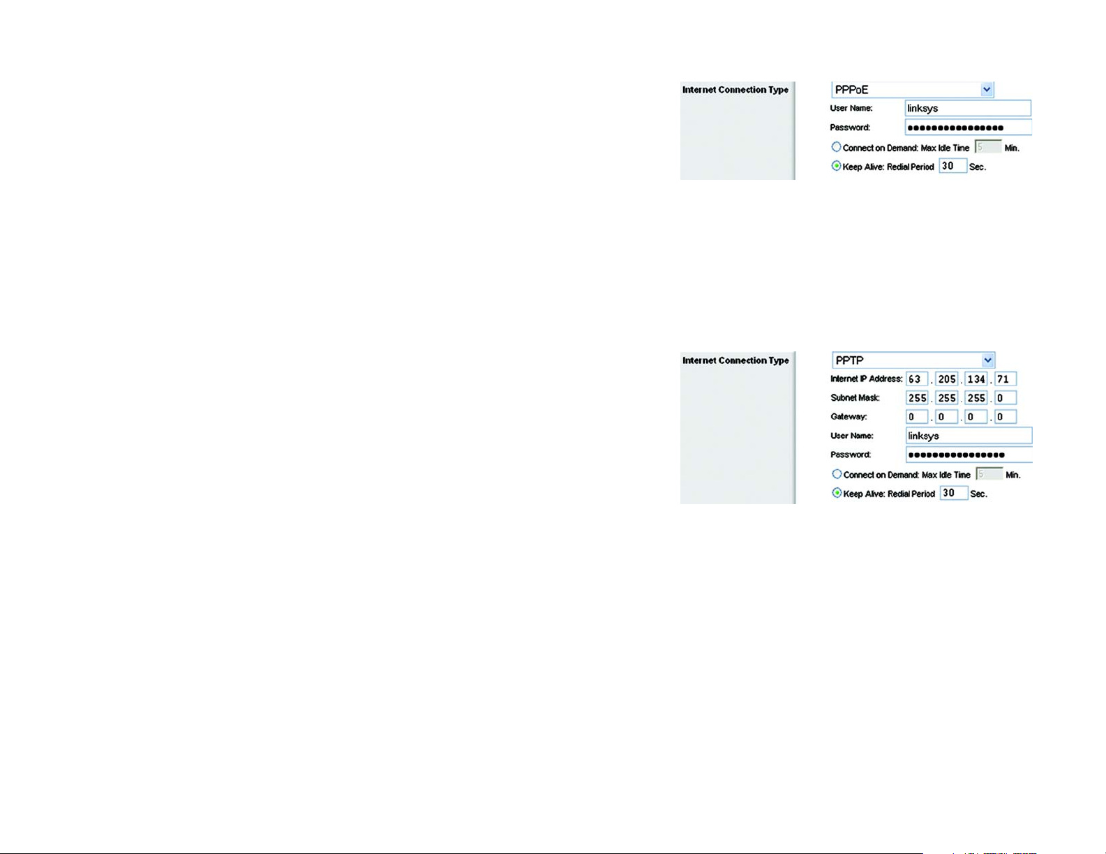
• PPPoE. Some DSL-based ISPs use PPPoE (Point-to-Point Protocol over Ethernet) to establish Internet
connections. If you are connected to the Internet through a DSL line, check with your ISP to see if they use
PPPoE. If they do, you will have to enable PPPoE.
User Name and Password. Enter the User Name and Password provided by your ISP.
Connect on Demand: Max Idle Time. You can configure the Router to cut the Internet connection after it has
been inactive for a specified period of time (Max Idle Time). If your Internet connection has been terminated
due to inactivity, Connect on Demand enables the Router to automatically re-establish your connection as
soon as you attempt to access the Internet again. If you wish to activate Connect on Demand, click the radio
button. In the Max Idle Time field, enter the number of minutes you want to have elapsed before your Internet
connection terminates.
Keep Alive Option: Redial Period. If you select this option, the Router will periodically check your Internet
connection. If you are disconnected, then the Router will automatically re-establish your connection. To use
this option, click the radio button next to Keep Alive. In the Redial Period field, you specify how often you want
the Router to check the Internet connection. The default Redial Period is 30 seconds.
• PPTP. Point-to-Point Tunneling Protocol (PPTP) is a service that applies to connections in Europe only.
Specify Internet IP Address. This is the Router’s IP address, as seen from the Internet. Your ISP will provide
you with the IP Address you need to specify here.
Subnet Mask. This is the Router’s Subnet Mask, as seen by users on the Internet (including your ISP). Your
ISP will provide you with the Subnet Mask.
Gateway. Your ISP will provide you with the Gateway Address.
User Name and Password. Enter the User Name and Password provided by your ISP.
Connect on Demand: Max Idle Time. You can configure the Router to cut the Internet connection after it has
been inactive for a specified period of time (Max Idle Time). If your Internet connection has been terminated
due to inactivity, Connect on Demand enables the Router to automatically re-establish your connection as
soon as you attempt to access the Internet again. If you wish to activate Connect on Demand, click the radio
button. In the Max Idle Time field, enter the number of minutes you want to have elapsed before your Internet
connection terminates.
Figure 5-5: PPPoE Connection Type
pppoe: a type of broadband connection that
provides authentication (username and
password) in addition to data transport
Figure 5-6: PPTP Connection Type
Keep Alive Option: Redial Period. If you select this option, the Router will periodically check your Internet
connection. If you are disconnected, then the Router will automatically re-establish your connection. To use
this option, click the radio button next to Keep Alive. In the Redial Period field, you specify how often you want
the Router to check the Internet connection. The default Redial Period is 30 seconds.
Chapter 5: Configuring the Wireless-G Broadband Router
The Setup Tab - Basic Setup
15
Wireless-G Broadband Router with SpeedBooster
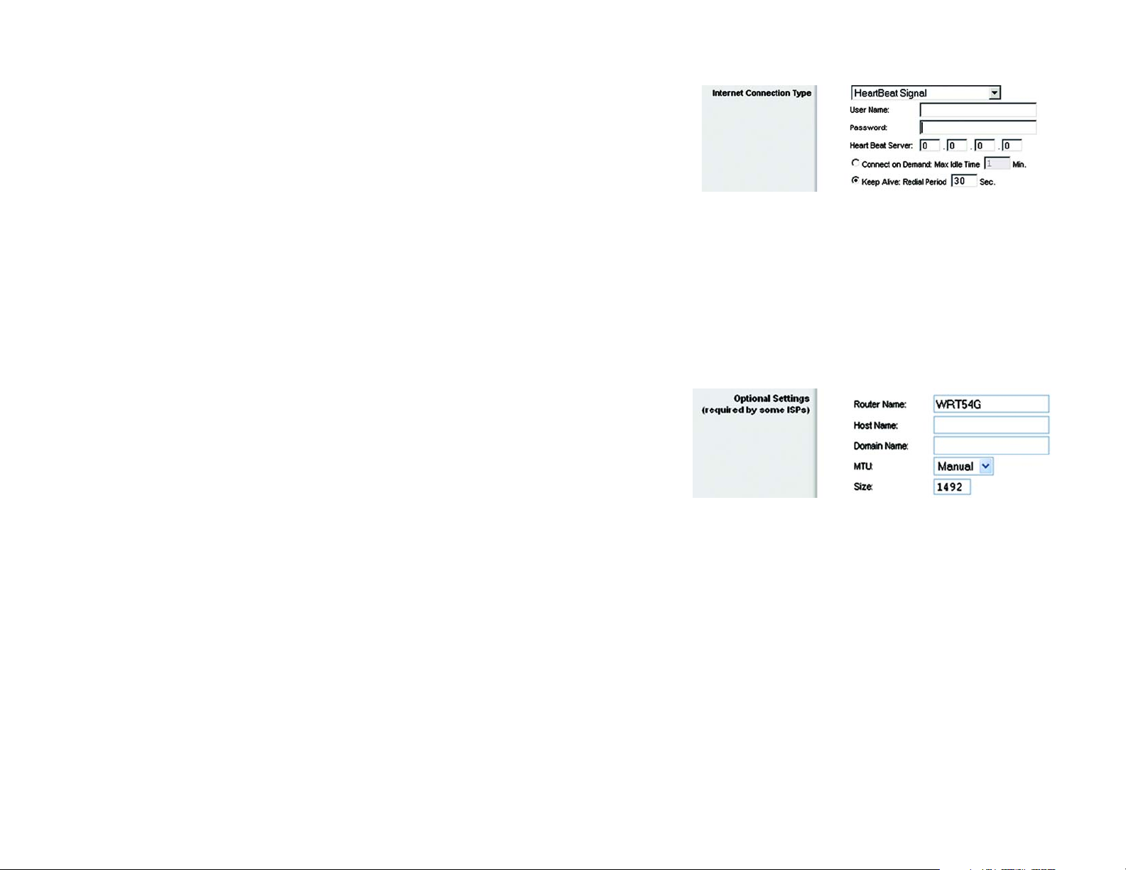
• HeartBeat Signal. HeartBeat Signal (HBS) is a service that applies to connections in Australia only.
User Name and Password. Enter the User Name and Password provided by your ISP.
Heart Beat Server. This is the IP address that the Router has, when seen from the Internet. Your ISP will
provide you with the IP Address you need to specify here.
Connect on Demand: Max Idle Time. You can configure the Router to cut the Internet connection after it has
been inactive for a specified period of time (Max Idle Time). If your Internet connection has been terminated
due to inactivity, Connect on Demand enables the Router to automatically re-establish your connection as
soon as you attempt to access the Internet again. If you wish to activate Connect on Demand, click the radio
button. In the Max Idle Time field, enter the number of minutes you want to have elapsed before your Internet
connection terminates.
Keep Alive Option: Redial Period. If you select this option, the Router will periodically check your Internet
connection. If you are disconnected, then the Router will automatically re-establish your connection. To use
this option, click the radio button next to Keep Alive. In the Redial Period field, you specify how often you want
the Router to check the Internet connection. The default Redial Period is 30 seconds.
Optional Settings
Some of these settings may be required by your ISP. Verify with your ISP before making any changes.
Router Name. In this field, you can type a name of up to 39 characters to represent the Router.
Host Name/Domain Name. These fields allow you to supply a host and domain name for the Router. Some
ISPs, usually cable ISPs, require these names as identification. You may have to check with your ISP to see if your
broadband Internet service has been configured with a host and domain name. In most cases, leaving these
fields blank will work.
MTU. MTU is the Maximum Transmission Unit. It specifies the largest packet size permitted for Internet
transmission. The default setting, Manual, allows you to enter the largest packet size that will be transmitted.
The recommended size, entered in the Size field, is 1492. You should leave this value in the 1200 to 1500 range.
To have the Router select the best MTU for your Internet connection, select Auto.
Figure 5-7: HeartBeat Signal Connection Type
Figure 5-8: Optional Settings
packet: a funit of data sent over a network
Network Setup
The Network Setup section changes the settings on the network connected to the Router’s Ethernet ports.
Wireless Setup is performed through the Wireless tab.
Chapter 5: Configuring the Wireless-G Broadband Router
The Setup Tab - Basic Setup
16

Wireless-G Broadband Router with SpeedBooster
Router IP
This presents both the Router’s IP Address and Subnet Mask as seen by your network.
Network Address Server Settings (DHCP)
The settings allow you to configure the Router’s Dynamic Host Configuration Protocol (DHCP) server function.
The Router can be used as a DHCP server for your network. A DHCP server automatically assigns an IP address
to each computer on your network. If you choose to enable the Router’s DHCP server option, you must configure
all of your network PCs to connect to a DHCP server (the Router), and make sure there is no other DHCP server
on your network.
DHCP Server. DHCP is enabled by factory default. If you already have a DHCP server on your network, or you
don’t want a DHCP server, then click the Disable radio button (no other DHCP features will be available).
Starting IP Address. Enter a value for the DHCP server to start with when issuing IP addresses. Because the
Router’s default IP address is 192.168.1.1, the Starting IP Address must be 192.168.1.2 or greater, but smaller
than 192.168.1.253. The default Starting IP Address is 192.168.1.100.
Maximum Number of DHCP Users. Enter the maximum number of PCs that you want the DHCP server to assign
IP addresses to. This number cannot be greater than 253. The default is 50.
Client Lease Time. The Client Lease Time is the amount of time a network user will be allowed connection to the
Router with their current dynamic IP address. Enter the amount of time, in minutes, that the user will be “leased”
this dynamic IP address. After the time is up, the user will be automatically assigned a new dynamic IP address.
The default is 0 minutes, which means one day.
Figure 5-9: Router IP
Figure 5-10: Network Address Server Settings
dynamic ip address: a temporary IP
address assigned by a DHCP server
Static DNS (1-3). The Domain Name System (DNS) is how the Internet translates domain or website names into
Internet addresses or URLs. Your ISP will provide you with at least one DNS Server IP Address. If you wish to use
another, type that IP Address in one of these fields. You can type up to three DNS Server IP Addresses here. The
Router will use these for quicker access to functioning DNS servers.
WINS. The Windows Internet Naming Service (WINS) manages each PC’s interaction with the Internet. If you use
a WINS server, enter that server’s IP Address here. Otherwise, leave this blank.
Time Setting
Change the time zone in which your network functions from this pull-down menu. (You can even automatically
adjust for daylight savings time.)
Chapter 5: Configuring the Wireless-G Broadband Router
The Setup Tab - Basic Setup
Figure 5-11: Time Setting
17
Wireless-G Broadband Router with SpeedBooster
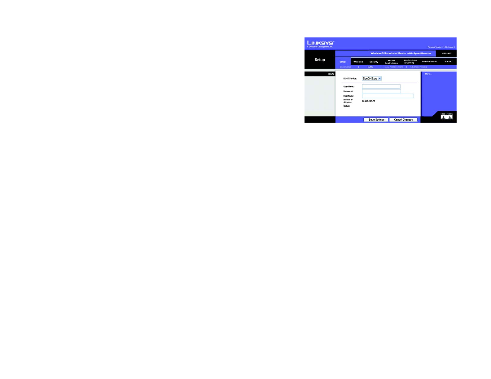
The Setup Tab - DDNS
The Router offers a Dynamic Domain Name System (DDNS) feature. DDNS lets you assign a fixed host and
domain name to a dynamic Internet IP address. It is useful when you are hosting your own website, FTP server, or
other server behind the Router. Before you can use this feature, you need to sign up for DDNS service at
www.dyndns.org or www.TZO.com, DDNS service providers.
DDNS Service. From this pull-down menu, enter the DDNS service with which you have membership.
User Name. Enter the User Name for your DDNS account
Password. Enter the Password for your DDNS account.
Host Name. The is the DDNS URL assigned by the DDNS service.
Figure 5-12: Setup Tab - DDNS
Internet IP Address. This is the Router’s current IP Address as seen on the Internet.
Status. This displays the status of the DDNS connection.
Change these settings as described here and click the Save Settings button to apply your changes or Cancel
Changes to cancel your changes.
ddns: allows the hosting of a website, FTP server, or
e-mail server with a fixed domain name (e.g.,
www.xyz.com) and a dynamic IP address
Chapter 5: Configuring the Wireless-G Broadband Router
The Setup Tab - DDNS
18

Wireless-G Broadband Router with SpeedBooster
The Setup Tab - MAC Address Clone
A MAC address is a 12-digit code assigned to a unique piece of hardware for identification. Some ISPs will
require you to register a MAC address in order to access the Internet. If you do not wish to re-register the MAC
address with your ISP, you may assign the MAC address you have currently registered with your ISP to the Router
with the MAC Address Clone feature.
Enable/Disable. To have the MAC Address cloned, click the radio button beside Enable.
User Defined Entry. Enter the MAC Address registered with your ISP here.
Clone Your PC’s MAC Address. Clicking this button will clone the MAC address.
Change these settings as described here and click the Save Settings button to apply your changes or Cancel
Changes to cancel your changes.
Figure 5-13: Setup Tab - MAC Address Clone
Chapter 5: Configuring the Wireless-G Broadband Router
The Setup Tab - MAC Address Clone
19

Wireless-G Broadband Router with SpeedBooster
The Setup Tab - Advanced Routing
This tab is used to set up the Router’s advanced functions. Operating Mode allows you to select the type(s) of
advanced functions you use. Dynamic Routing will automatically adjust how packets travel on your network. Static
Routing sets up a fixed route to another network destination.
Operating Mode
connection to the Internet, select
chosen,
Dynamic Routing
Dynamic Routing
. Select the mode in which this Router will function. If this Router is hosting your network’s
Gateway
. If another Router exists on your network, select
Router
. When Router is
will be enabled.
. This feature enables the Router to automatically adjust to physical changes in the network’s
layout and exchange routing tables with the other router(s). The Router determines the network packets’ route
based on the fewest number of hops between the source and the destination. This feature is
From the drop-down menu, you can also select
Ethernet and wireless networks. You can also select
the Internet. Finally, selecting
Static Routing
. To set up a static route between the Router and another network, select a number from the Static
Both
enables dynamic routing for both networks, as well as data from the Internet.
LAN & Wireless
WAN
, which performs dynamic routing with data coming from
, which performs dynamic routing over your
Disabled
by default.
Routing drop-down list. (A static route is a pre-determined pathway that network information must travel to reach a
specific host or network.) Enter the information described below to set up a new static route. (Click the
Entry
button to delete a static route.)
Enter Route Name
Destination LAN IP
. Enter a name for the Route here, using a maximum of 25 alphanumeric characters.
. The Destination LAN IP is the address of the remote network or host to which you want to
Delete This
assign a static route.
Subnet Mask
. The Subnet Mask determines which portion of a Destination LAN IP address is the network
portion, and which portion is the host portion.
Default Gateway
. This is the IP address of the gateway device that allows for contact between the Router and
the remote network or host.
Figure 5-14: Setup Tab - Advanced Routing (Gateway)
Interface
wireless networks), the
. This interface tells you whether the Destination IP Address is on the
WAN
(Internet), or
Loopback
necessary for certain software programs).
Click the
Change these settings as described here and click the
Changes
Chapter 5: Configuring the Wireless-G Broadband Router
The Setup Tab - Advanced Routing
Show Routing Table
to cancel your changes.
button to view the Static Routes you’ve already set up.
Save Settings
LAN & Wireless
(Ethernet and
(a dummy network in which one PC acts like a network—
button to apply your changes or
Cancel
Figure 5-15: Setup Tab - Advanced Routing (Router)
default gateway: a device that forwards
Internet traffic from your local area network
20
Wireless-G Broadband Router with SpeedBooster
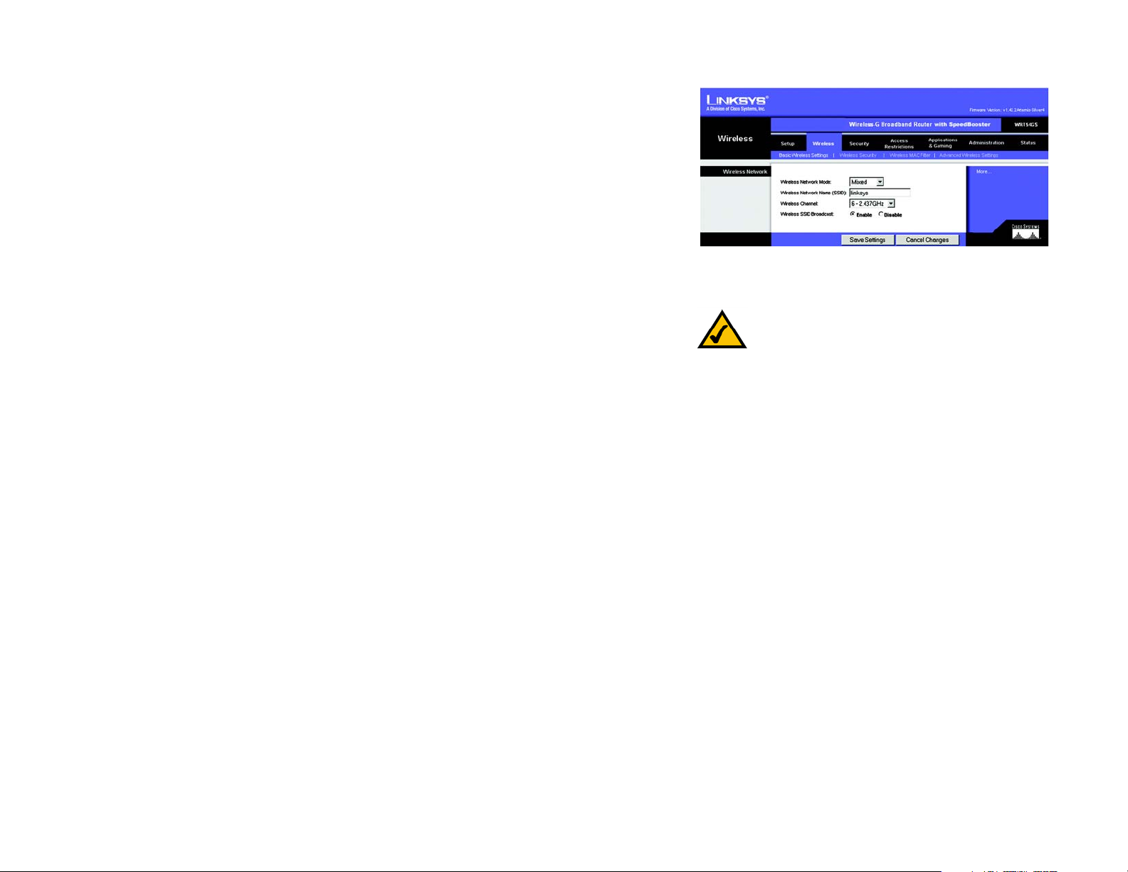
The Wireless Tab - Basic Wireless Settings
The basic settings for wireless networking are set on this screen.
Wireless Network Mode. From this drop-down menu, you can select the wireless standards running on your
network. If you have both 802.11g and 802.11b devices in your network, keep the default setting, Mixed. If you
have only 802.11g devices, select G-Only. If you have only 802.11b devices, select B-Only. If you do not have any
802.11g and 802.11b devices in your network, select Disable. SpeedBooster works automatically with all
settings, providing the added bonus of increased speed across your entire network and even greater speed when
using SpeedBooster products only.
Wireless Network Name (SSID). The SSID is the network name shared among all points in a wireless network.
The SSID must be identical for all devices in the wireless network. It is case-sensitive and must not exceed 32
characters (use any of the characters on the keyboard). Make sure this setting is the same for all points in your
wireless network. For added security, you should change the default SSID (linksys) to a unique name.
Wireless Channel. Select the appropriate channel from the list provided to correspond with your network
settings. All devices in your wireless network must be broadcast on the same channel in order to function
correctly.
Wireless SSID Broadcast. When wireless clients survey the local area for wireless networks to associate with,
they will detect the SSID broadcast by the Router. To broadcast the Router's SSID, keep the default setting,
Enable. If you do not want to broadcast the Router's SSID, then select Disable.
Figure 5-16: Wireless Tab - Basic Wireless Settings
NOTE: SpeedBooster ONLY works in Infrastructure
Mode.
Change these settings as described here and click the Save Settings button to apply your changes or Cancel
Changes to cancel your changes.
Chapter 5: Configuring the Wireless-G Broadband Router
The Wireless Tab - Basic Wireless Settings
21

Wireless-G Broadband Router with SpeedBooster
The Wireless Tab - Wireless Security
The Wireless Security settings configure the security of your wireless network. There are four wireless security
mode options supported by the Router: WPA Pre-Shared Key, WPA RADIUS, RADIUS, and WEP. (WPA stands for WiFi Protected Access, which is a security standard stronger than WEP encryption. WEP stands for Wired Equivalent
Privacy, while RADIUS stands for Remote Authentication Dial-In User Service.) These four are briefly discussed
here. For detailed instructions on configuring wireless security for the Router, turn to “Appendix B: Wireless
Security.”
WPA Pre-Shared Key. WPA gives you two encryption methods, TKIP and AES, with dynamic encryption keys.
Select the type of algorithm, TKIP or AES. Enter a WPA Shared Key of 8-63 characters. Then enter a Group Key
Renewal period, which instructs the Router how often it should change the encryption keys.
WPA RADIUS. This option features WPA used in coordination with a RADIUS server. (This should only be used
when a RADIUS server is connected to the Router.) First, select the type of WPA algorithm you want to use, TKIP
or AES. Enter the RADIUS server’s IP Address and port number, along with a key shared between the Router and
the server. Last, enter a Key Renewal Timeout, which instructs the Router how often it should change the
encryption keys.
IMPORTANT: If you are using WPA, always
remember that each device in your wireless
network MUST use the same WPA method
and shared key, or else the network will not
function properly.
Figure 5-17: Wireless Tab - Wireless Security
(WPA Pre-Shared Key)
Chapter 5: Configuring the Wireless-G Broadband Router
The Wireless Tab - Wireless Security
Figure 5-18: Wireless Tab - Wireless Security
(WPA RADIUS)
radius: a protocol that uses an authentication
server to control network access
22

Wireless-G Broadband Router with SpeedBooster
RADIUS. This option features WEP used in coordination with a RADIUS server. (This should only be used when a
RADIUS server is connected to the Router.) First, enter the RADIUS server’s IP Address and port number, along
with a key shared between the Router and the server. Then, select a Default Transmit Key (choose which Key to
use), and a level of WEP encryption, 64 bits 10 hex digits or 128 bits 26 hex digits. Last, either generate a
WEP key using the Passphrase or enter the WEP key manually.
WEP. WEP is a basic encryption method, which is not as secure as WPA. To use WEP, select a Default Transmit
Key (choose which Key to use), and a level of WEP encryption, 64 bits 10 hex digits or 128 bits 26 hex digits.
Then either generate a WEP key using the Passphrase or enter the WEP key manually.
Change these settings as described here and click the Save Settings button to apply your changes or Cancel
Changes to cancel your changes. For detailed instructions on configuring wireless security for the Router, turn to
“Appendix B: Wireless Security.”
IMPORTANT: If you are using WEP
encryption, always remember that each
device in your wireless network MUST use
the same WEP encryption method and
encryption key, or else your wireless network
Figure 5-19: Wireless Tab - Wireless Security (RADIUS)
Chapter 5: Configuring the Wireless-G Broadband Router
The Wireless Tab - Wireless Security
Figure 5-20: Wireless Tab - Wireless Security (WEP)
23
 Loading...