

Linksys VGA2100 - One Analog Voice Gateway 3 Line, SVR3000, PHM1200, PHB1100, VGA2000 Administration Manual
...Page 1

CUSTOMER PREMISES EQUIPMENT ADMINISTRATION GUIDE
Customer Premises Equipment
Administration Guide
Release 1.1
Page 2

i
Linksys One Communications Solution
Contents
Chapter 1: Welcome to Linksys One - - - - - - - - - - - - - - - - - - -1
Welcome VARs! 1
About this Guide... 1
What is the Linksys One Communications Solution? 3
Basic Data Infrastructure 3
Integrated Office Applications 4
Support Solution 4
What is Linksys One Customer Premises Equipment? 4
Linksys One SVR3000 16-Port Services Router 5
SVR3000 Power Supply 5
Rack and Wall Mountable 5
How the SVR3000 Works With the Linksys One Network 5
LED Behavior 7
Using the USB Memory Key for Voice Mail Storage 7
Linksys One IP Phones 8
Emergency Services (911) 8
Linksys One PHM1200 IP Phone 9
Linksys One PHB1100 IP Phone 9
Phone Hardware Features 10
Integrated Voice Features A to Z 11
Programmable Buttons 14
Graphical Phone Screen Interface 15
Linksys One Voice Gateways 16
Linksys One VGA2000 Analog Voice Gateway 16
Linksys One VGA2100 Analog Voice Gateway 20
Linksys One VGA2200 Analog Voice Gateway 23
Chapter 2: Start Here! - - - - - - - - - - - - - - - - - - - - - - - - 27
Step 1: Prepare for Installation. 27
Step 2: Provision Your Customer on the Service Node. 27
Step 3: Install the Services Router. 28
Step 4: Connect One Phone to the Services Router. 28
Step 5: Observe the Phone Boot Process. 28
Page 3

ii
Linksys One Communications Solution
Step 6: Enter Handshake Information. 28
Step 7: Connect Additional Phones. 29
Step 8: Add Linksys One Voice Gateways. 29
Step 9: Customize the Phone System. 30
Step 10: Provide Information to Phone Users. 30
Step 11: Administer the Network. 30
Step 12: Troubleshoot Problems. 30
Chapter 3: Preparing for Installation - - - - - - - - - - - - - - - - - 31
Preparing the Site 31
Site Environmental Considerations 32
Cabling Requirements 37
Installation Tools and Equipment 37
Services Router Mounting Specifications 37
Equipment Layout for Installation 38
CPE Capacity Planning 39
Network Requirements 40
Additional Site Considerations 44
Establishing a Customer on the Service Node 49
Adding a Customer 50
Chapter 4: Installation - - - - - - - - - - - - - - - - - - - - - - - - 55
Installing the Services Router 55
Installing One Services Router 55
Verifying Your Services Router Installation 57
Installing Two Services Routers 58
Installing Linksys One Phones 60
Connecting the Handshake Phone 61
Adding Computers to the Network 63
Connecting Computers Directly to the Services Router 63
Connecting Computers Via the Linksys One IP Phone 63
Verifying the Computer Installation 64
Adding a Linksys One Voice Gateway to the Network 64
Installing a VGA2000 Voice Gateway 64
Installing a VGA2100 Voice Gateway 67
Installing a VGA2200 Voice Gateway 69
Normal Operation for the Linksys One Voice Gateways 70
Page 4

iii
Linksys One Communications Solution
Chapter 5: Administering the Phone System - - - - - - - - - - - - - - 73
Which Settings Can I Customize? 73
Which Settings Can Users Customize? 73
Accessing the Administration Editor 73
Using the Actions Index Window 75
How do I change a setting? 75
When do my changes take effect? 76
Online Help 78
Viewing Suggestions for Provisioning Your System 78
Understanding Visual Queues on the Administration Editor Screens 78
Configuring Site Settings 79
Managing the User Directory 79
Setting the System Maintenance Window 83
Changing the System Administrator Password 84
Administering the Auto Attendant 84
Viewing Line Status 89
Deleting Out-of-Service Devices 89
Editing the Device Label 89
Configuring Phone Settings 90
Viewing and Changing Device Assignments 90
Assigning a Phone Line to an FXS Port 91
Changing the Phone Assigned to a User 92
Deleting a User from the Database 93
Deleting a Phone or Voice Gateway from the Database 93
Defining Line Assignments and Line Settings 94
Defining User Settings 99
Configuring Call Handling Options 102
Managing Phone Button Assignments 103
Administering Voice Mailboxes 107
Managing Data Devices and Data Settings 109
Viewing the Status of Data Devices 109
Pinging a Data Device 110
Chapter 6: Using Your Phone - - - - - - - - - - - - - - - - - - - - 117
Getting to Know Your Phone 117
Linksys One PHM1200 IP Phone 118
Page 5

iv
Linksys One Communications Solution
Linksys One PHB1100 IP Phone 118
Understanding Phone Buttons and Features 119
Understanding the Phone Screen 120
Understanding Your Phone Passwords 121
Common Phone Features 122
Basic Call Handling 123
Advanced Call Handling 128
Using Voice Mail 130
How do I access voice mail? 131
How do I set up voice mail? 133
Using the Auto Attendant 136
How do I access the Auto Attendant application? 136
How do I manage the Auto Attendant application? 136
Using Your User Settings Page 140
How do I access my User Settings page? 140
How do I change my password? 141
How do I set my Auto Dials? 141
How do I view my phone button assignments? 142
How do I print my phone button template? 142
Managing Phone Button Assignments 145
Chapter 7: Administering the Network - - - - - - - - - - - - - - - -147
How Does the Database Get Backed Up? 147
How Does the Phone System Get Upgraded? 148
Moving, Adding, and Deleting Devices on the Network 149
Moving a User to a New Location 149
Adding a Phone to the Network 150
Deleting a Phone or Voice Gateway from the Database 150
Deleting a User from the Database 151
Replacing a Services Router on the Network 151
Using the Customer Support Interface 152
Accessing the Customer Support Interface 152
Viewing Device Status At-A-Glance 154
Viewing Customer Information 155
Administering the Services Router 156
Using the SVR3000 Tab 157
Configuring a Static WAN IP Address 158
Page 6

v
Linksys One Communications Solution
Viewing the IP Address and MAC Address 159
Viewing the Software Version 159
Viewing Status for the CPE to Service Node Relationship 160
Viewing Information About the Data Network 161
Restarting the Services Router 162
Cleaning the Services Router for Re-installation or Re-handshaking 162
Restoring the CPE database 163
Resetting the Services Router to Factory Defaults 163
Administering the Phones 165
Viewing the Software Version Running on the Phone 165
Restarting a Phone 165
Restarting Multiple Phones 166
Administering the Voice Gateways 166
Restarting a Voice Gateway 166
Changing the Location ID for the Voice Gateway 166
Changing the Line ID for the Voice Gateway 167
Adjusting the Gain Settings for the Voice Gateway 168
Sending and Receiving Diagnostic Information 168
Chapter 8: Troubleshooting - - - - - - - - - - - - - - - - - - - - - 169
Troubleshooting Installation 169
Troubleshooting the Services Router 170
Troubleshooting the Phone 174
Troubleshooting the Voice Gateway 178
Troubleshooting Connected Devices 180
Additional Troubleshooting Documentation 180
Appendix A: Customer Site Survey - - - - - - - - - - - - - - - - - - 181
Appendix B: Linksys One Contact Information - - - - - - - - - - - - 185
Page 7

vi
Linksys One Communications Solution
Page 8

1
Chapter 1: Welcome to Linksys One
Welcome VARs!
Linksys One Communications Solution
Chapter
1
Welcome to Linksys One
Thank you for choosing Linksys One, a complete, affordable, easy-to-install communications
solution for small businesses. Linksys One delivers telephones, data networking,
applications, and the Internet through one high-speed connection from a Hosted Service
Provider. The system provides IP-based voice and data services with built-in security,
reliability and premium call quality. With Linksys One, the network instantly detects new
Linksys One devices and automatically configures them for optimal performance and simple
management. Phones install in minutes, not the hours or days it takes with other solutions.
Welcome VARs!
Linksys One delivers the communications solutions your customers want at the price they
need. As your customers’ businesses grow, you can help them easily connect new users, and
sell additional technologies, such as video surveillance, while enabling the customer to
protect their original investment. For example, Linksys One carriers will offer future high-
value Internet-based application services that provide smarter ways to transact business.
Linksys One resellers can leverage this momentum and create a foundation to sell additional
services. For resellers, this is a great opportunity to grow your revenue and profit potential.
You can capitalize on the growing demand for IP-based services with a more affordable,
simpler and complete small business communications solution.
About this Guide...
The Linksys One Customer Premises Equipment Administration Guide is intended for
qualified Value Added Resellers (VARs) who are installing, administering, and managing the
Linksys One customer premises equipment (CPE). The guide assumes you have completed
the Linksys One training and are familiar with all system software configuration and
hardware installation procedures. The following topics are included:
• Chapter 1 "Welcome to Linksys One" provides an overview of this guide and a
description of the Linksys One products and features.
• Chapter 2 "Start Here!" provides a “cheat sheet” for installing the Linksys One CPE
using default settings.
• Chapter 3 "Preparing for Installation" describes how to plan for and deploy Linksys
One Customer Premises Equipment (CPE).
Automatic Configuration
Linksys One uses a network discovery process
with automated configuration which means that
new networks—as well as moves adds and
changes—are fast and easy. As soon as they’re
plugged in, Linksys One devices automatically
determine the optimal configuration and are
ready to go.
Page 9

Chapter
1
2
Chapter 1: Welcome to Linksys One
About this Guide...
Linksys One Communications Solution
• Chapter 4 "Installation" provides instructions for how to install the Linksys One
hardware components.
• Chapter 5 "Administering the Phone System" describes how to use the Linksys One
Administration Editor to customize site-wide, voice, and data settings. This section
explains how to configure call routing settings, too.
• Chapter 6 "Using Your Phone" describes how to use the phone features including
how to set up and use voice mail, how to manage the Auto Attendant greetings, and
how to access the User Settings page for configuring Auto Dials, call forward
settings, and the user’s password. If desired, you can “brand” this and distribute to
your customers.
• Chapter 7 "Administering the Network" helps you understand how devices and
phones get automatically backed up and upgraded on the Linksys One network.It
also describes how to view device status, how to add, remove, and move devices,
and how to administer the Services Router, the phones, and the voice gateways.
• Chapter 8 "Troubleshooting" provides solutions to common problems you may
encounter on your Linksys One network.
• Appendix A "Customer Site Survey" provides a form to help you gather information
for your customer’s site.
• Appendix B "Linksys One Contact Information" provides a phone number, URL and
E-mail address for contacting Linksys One.
Page 10
3
Chapter 1: Welcome to Linksys One
What is the Linksys One Communications Solution?
Linksys One Communications Solution
Chapter
1
What is the Linksys One Communications Solution?
The Linksys One Communications Solution is a low-cost, distributed, (SIP) based system with
full Key System features serving the small business (5-50 users) segment. Based on the
Internet model which enables rapid development of features and applications, the Linksys
One solution can be deployed in a standalone fashion or in a managed solution.
The Linksys One solution features three components:
• An infrastructure that supports IP networking and business-class applications, such
as Voice over Internet Protocol (VoIP),
• Integrated office applications
• A support offering
Basic Data Infrastructure
The basic data infrastructure components and services include:
• A SVR3000 Services Router that provides IP routing, Network Address Translation
(NAT), Stateful Packet Inspection (SPI) firewall, Session Initiation Protocol –
Application Layer Gateway (SIP ALG), wired Ethernet LAN ports w/POE support
and Internet Access via 10/100 Ethernet.
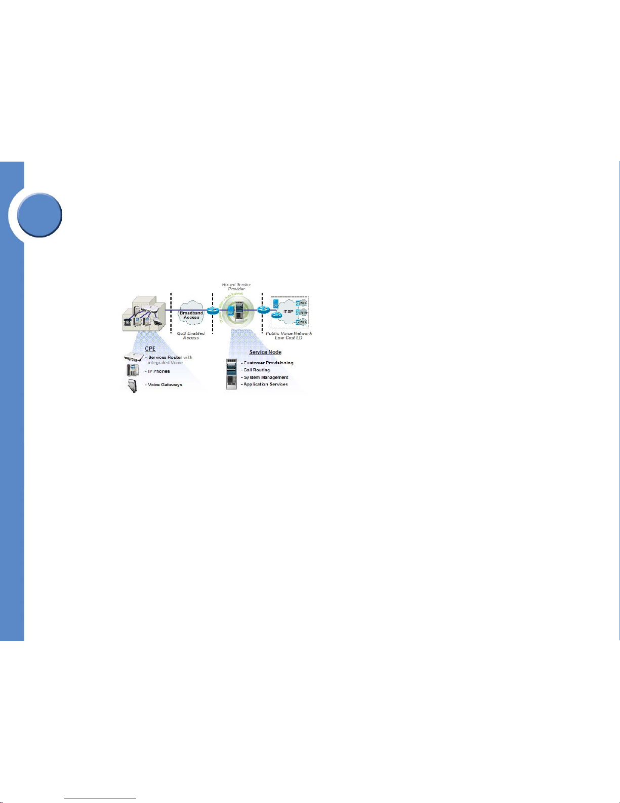
Broadband Access Provider (BAP). DSL, Cable, or
T1 service provided by the HSP. The BAP has
Linksys One CPN-designation for QoS-enabled
access.
Service Node: Equipment at the HSP’s site that
provides extended applications and call
processing services to your customer. It also
enables voice and data connectivity from the
Broadband Access Provider (BAP) interface to the
Internet Telephony Services Provider (ITSP)
interface.
Hosted Services Provider (HSP): A Service
Provider that owns the managed service and call
routing components of the Linksys One system,
including the Service Node. Via the Service Node,
the HSP remotely manages and optimizes the
Linksys One network.
Page 11

Chapter
1
4
Chapter 1: Welcome to Linksys One
What is Linksys One Customer Premises Equipment?
Linksys One Communications Solution
• Voice-specific devices including the PHM1200 and PHB1100 IP Phones, and three
analog Voice Gateways (VGA2000, VGA2100, and VGA2200). These products
are used for integration with analog Public Switched Telephone Network (PSTN)
infrastructures.
Integrated Office Applications
The application capabilities for the Linksys One solution include:
• Automatic software upgrades, under management control, whenever new versions
are released.
• A 3-way conferencing capability, built-in Auto Attendant function for the voice
system, graphical voice mail, and an automatic backup/restore capability for device
configurations.
Support Solution
The Support solution includes:
• A web-based management portal that enables remote maintenance and monitoring
of customer site equipment
• An 800 number for technical assistance to Linksys’ Business Assistance Center.
What is Linksys One Customer Premises Equipment?
The Linksys One customer premises equipment (CPE) consists of the following components:
• Linksys One SVR3000 16-Port Services Router
• Linksys One IP Phones (models PHM1200 and PHB1100)
• Linksys One Voice Gateways (models VGA2000, VGA2100, VGA2200)
Page 12
5
Chapter 1: Welcome to Linksys One
Linksys One SVR3000 16-Port Services Router
Linksys One Communications Solution
Chapter
1
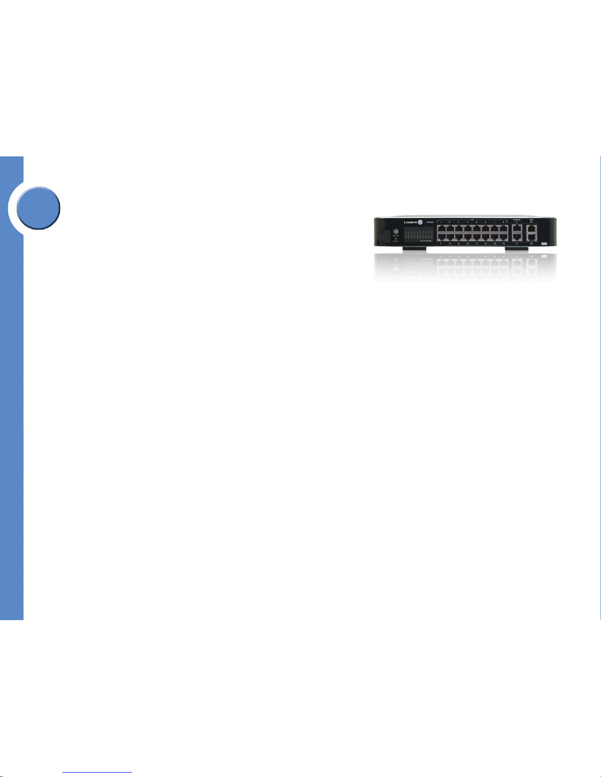
Linksys One SVR3000 16-Port Services Router
The Linksys One SVR3000 Services Router is the central component of the Linkys One CPE
solution and is therefore required for your Linksys One network. It features onboard software
that integrates security, reliability and quality of service to support business quality Linksys
One communications services.
All SVR3000s are identical to each other from the factory. No pre-configuration is required
to configure the SVR3000 at the customer site. A "handshake" procedure is all that is
needed to establish a baseline configuration for each customer. The baseline configuration
contains customer specific information supplied when the customer was provisioned on the
Service Node..
If an SVR3000 fails for some reason (hardware, software, natural disaster, etc.) and needs
to be replaced, the new unit can be configured by utilizing the same information provided
during the customer establishment process. Plug in the new device, restore the backup, and it
will set up within minutes with an identical configuration.
SVR3000 Power Supply
The SVR3000 power supply requires an AC input voltage of anywhere from 100 to 240
volts, 50 or 60 Hz for universal operation around the globe. The power cord is a standard
IEC connector, commonly used on computer equipment. Although the power cord is included
with the kit, you can easily obtain a new one from most any computer or electronics supply
store around the world.
Rack and Wall Mountable
The SVR3000 is rack and wall-mountable. Instructions for mounting the SVR3000 are
included in the box and also in Appendix A of this guide.
How the SVR3000 Works With the Linksys One Network
The SVR3000 has 16 LAN ports with 10/100 Ethernet and IEEE Standard Power-overEthernet (POE). All 16 attached devices (phones, gateways, other devices in the future) may
be powered by the POE simultaneously.
• Two “cascade” Gigabit Ethernet ports may be used to increase the port count with
additional SVR3000s, or alternatively used for a Network Attached Storage (NAS)
drive in the future.
Page 13
Chapter
1
6
Chapter 1: Welcome to Linksys One
Linksys One SVR3000 16-Port Services Router
Linksys One Communications Solution
• The voice and data VLANs separate traffic, ensuring that the right devices are
allowed to tag traffic while providing security for voice traffic, DSCP markings used
by the multiple queues on the WAN port supply the QoS
• Two 10/100 WAN ports connect to the Internet. The SVR3000 automatically gets an
IP address via DNS/DHCP.
• The SVR3000 has the following servers built in: SIP proxy supporting IETF standard
RFC3261 for call routing, DNS/DHCP, configuration and image servers. The
SVR3000 uses the configuration and image servers to store the configuration and
the device images (phones, gateways, etc.) obtained during the handshake process.
• For security and proper traffic management at the CPE, the SVR3000 includes a
built-in Stateful Packet Inspection (SPI) Firewall, an Application Layer Gateway (ALG)
and support for multiple IPSec VPN Tunnels (for future remote office capabilities).
• The SVR3000 also includes a USB 2.0 port for local storage (flash memory key).
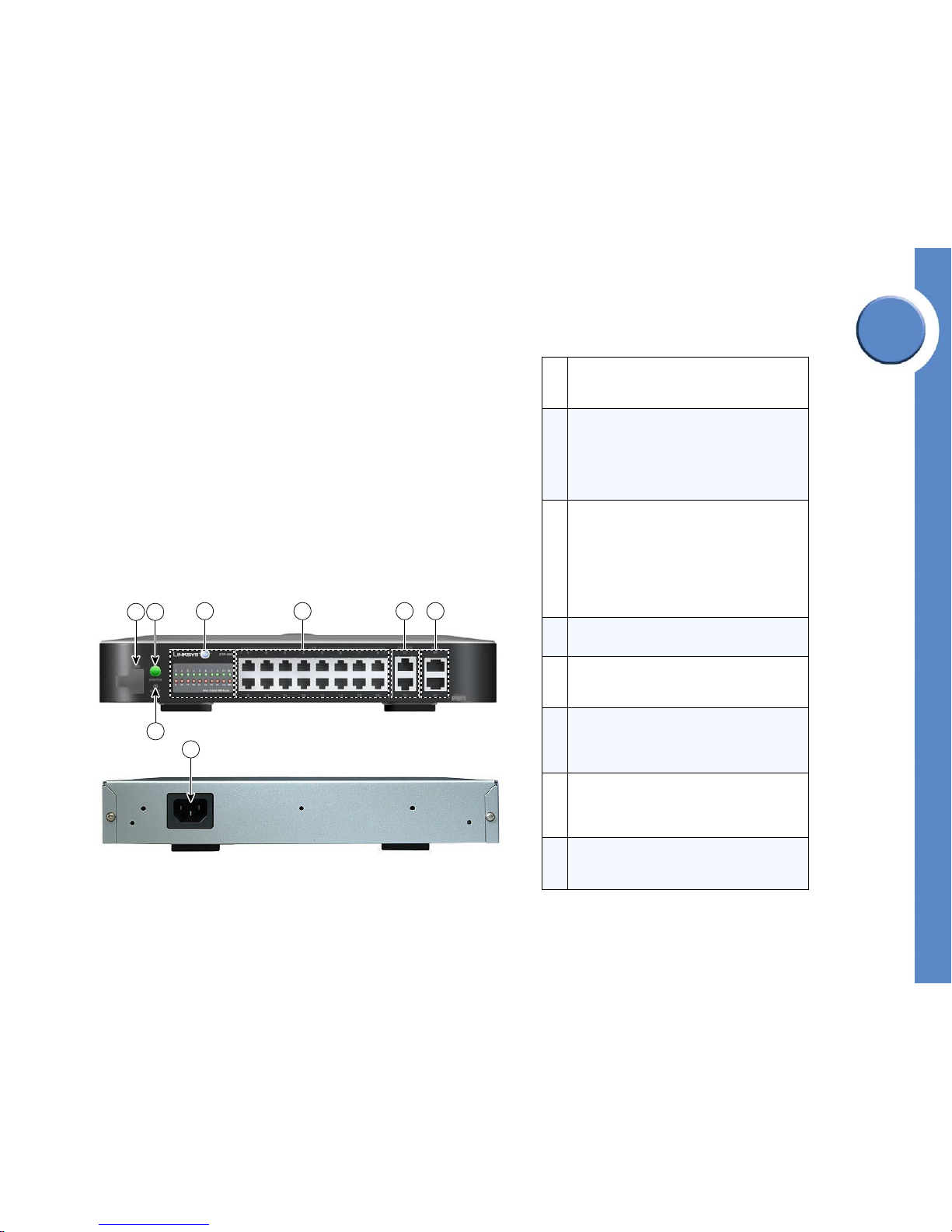
Linksys One SVR3000 Services Router (front and rear panel)
1
LAN Ports. The 16 LAN ports provide full support
for IEEE 802.3af PoE. Up to two VLANs are
supported per LAN port.
2
CASCADE Ports. Two 10/100/1000 BaseT ports
offer cascaded expansion to other service routers
and application servers. You can connect two
SVR3000’s via the cascade ports. You can
configure multiple Virtual LANs per cascade port
(i.e., 802.1Q/P capable).
3
WAN Ports. Two 10/100 WAN ports provide
access to the Internet either directly or through a
separate broadband router or bridge device. The
WAN ports perform load-balancing with fail-over
capability, allowing high-priority traffic such as
voice, to be routed out a specified broadband
connection while low-priority traffic is routed out
the other broadband connection.
4
LEDs. Indicate port connection status and port
activity. See "LED Behavior” at left.
5
SYSTEM Button. Indicates the overall status for the
SVR3000 and whether the SVR3000 is in cascade
mode.
6
RESET Button. Reboots the SVR3000 or resets the
SVR3000 to the factory defaults. See ”Restarting
the Services Router” section on page 162 for
details on how to use the RESET button.
7
USB Port. Connects a memory key for storing
voice mail. The USB port accepts the USB 2.0compliant, 512MB memory key that is shipped in
the box with the SVR3000.
8
Power Port. Connects the SVR3000 to power.
Note that there is no power ON/OFF switch on
the SVR3000.
144876
587
4 1 2 3
6
Page 14

7
Chapter 1: Welcome to Linksys One
Linksys One SVR3000 16-Port Services Router
Linksys One Communications Solution
Chapter
1
LED Behavior
Using the USB Memory Key for Voice Mail Storage
All voice mail and greetings for the phone system are stored on the USB memory key. When
users choose to “shred” voice mail via the graphical interface on the phones, the space on
the USB key is immediately freed. If users “trash” voice mail, the space on the memory key
will be freed as needed to make room for voice mail. The USB key is also used for a local
CPE configuration backup.
The memory key should be plugged in to the SVR3000 at all times. If it is not, the system will
not operate properly and voice mail data can be lost. Be sure to use only the USB memory
key included in the box with the SVR3000 as it meets the high-quality specifications required
for use with the Linksys One phone system.
SYSTEM LED Solid green when the Services Router is operating properly. Flashes between
green and red in one-second intervals to indicate that a new image is
loading. When in cascade mode, flashes in intervals of five seconds green
and one second red.
LAN LED Green to indicate a device is connected to that port.
WAN LED Flashes green when there is activity on the WAN port.
IMPORTANT: The USB flash memory key
is used for voice mail storage and must
be plugged in to the Services Router at
all times for proper operation.
USB
144552
USB
Page 15

Chapter
1
8
Chapter 1: Welcome to Linksys One
Linksys One IP Phones
Linksys One Communications Solution
Linksys One IP Phones
The Linksys One solution offers two IP Phones to meet your customer’s business needs:
• Linksys One PHM1200 IP Phone
• Linksys One PHB1100 IP Phone
The Linksys One IP phones work like a desktop business phone, but operate over Ethernet
which makes it very easy and cost-effective to deploy. Linksys One technology is automatic
and self-configuring. Simply plug in a Linksys One phone to the Linksys One Services Router
switch port and you’ll be ready to make and receive quality calls using Voice over Internet
Protocol (VoIP). The Linksys One phones deliver traditional telephony services to the small
business user such as call forwarding, transfer, busy lamp field and shared line appearances
on a next-generation IP phone platform.
Emergency Services (911)
Emergency Services (911) calls can be made from any phone on your Linksys One network.
Emergency services calls from the site can be routed to the public telephone network via the
FXO port on the local Linksys One Voice Gateway. If there is a power loss that affects the
Linksys One network equipment, the relay switch in the Voice Gateways automatically draws
power from the local FXO loop. If an analog phone is connected to the FXS port, it can be
used to make an emergency services call regardless of a power failure
The FXO ports on the VGA2100 and VGA2200 Voice Gateways support inbound calls from
the public telephone network, for example, callbacks from the 911 operator (PSAP).
However, the VGA2000 Voice Gateway does not.
IMPORTANT: The VGA2000 Voice
Gateway does not accept inbound calls
from the public telephone network;
therefore, callbacks on that line from the
911 operator (PSAP) are not supported.
Page 16

9
Chapter 1: Welcome to Linksys One
Linksys One IP Phones
Linksys One Communications Solution
Chapter
1
Linksys One PHM1200 IP Phone
The Linksys One PHM1200 IP telephone is the workhorse wired desk phone for today's
business user. Primary features include:
• High-resolution (320 X 240) color, backlit display
• 24 programmable buttons with integrated status indication
•4 softkeys
• 3 fixed function keys
• 5-position navigation key
• Full-duplex speakerphone
• Handset and headset ports for superlative audio quality, volume control and muting
control.
Linksys One PHB1100 IP Phone
The Linksys One PHB1100 IP Telephone provides streamlined functionality to users and
common areas. A backlit pixel-based display with dedicated feature buttons and
speakerphone speed common phone operations.
Primary features include:
• Monochrome (192 X 64) blue backlit pixel-based display
• 24 programmable buttons with integrated status indication
•4 softkeys
• 3 fixed function keys
• 3-position navigation key
Linkys One PHM1200 IP Phone
Linkys One PHB1100 IP Phone
Page 17

Chapter
1
10
Chapter 1: Welcome to Linksys One
Linksys One IP Phones
Linksys One Communications Solution
• Full-duplex speakerphone
• Handset and headset ports for superlative audio quality, volume control and muting
control..
Phone Hardware Features
All Linksys One phones provide the following hardware features:
Ports and Power
An integrated quality of service enabled 10/100 switch provides wired network access for
the phone plus an attached PC. The upstream port accepts IEEE PoE (802.3af) and fully
powers the phone and connected media devices.
Hardware Feature Description
10/100 Ethernet switch
Allows a phone and a PC to be connected to the same
Ethernet port on the SVR3000. With one SVR3000, 16
Linksys One IP phones and 16 PCs may be connected to
the SVR3000 and operate simultaneously.
Optional DC power supply
Although the phones are powered over Ethernet (POE), you can
optionally connect a DC power supply (ordered separately) on the
rear of the phone next to the handset, headset, and Ethernet
ports.
Page 18

11
Chapter 1: Welcome to Linksys One
Linksys One IP Phones
Linksys One Communications Solution
Chapter
1
Integrated Voice Features A to Z
An integrated voice mail application provides cost-effective, high-quality voice messaging
service with both local and remote access to stored messages. The Linksys One phones also
feature a built-in Auto Attendant as well as a rich set of features described below:
Voice Feature Description
3-way Conference Conference call between 3 parties is bridged locally on the IP Phones.
Busy Lamp Field
(BLF)
Allows a user/phone to monitor the status of another IP Phone via an LED
button on the phone.
Call Hold Places an active call on hold (plays music-on-hold to held party).
Call Park / Pickup
Call is placed on hold, and retrieved by another phone by dialing a virtual
extension number.
Call Transfer Active call is sent from one phone to another phone.
Caller ID
Telephone number and name of the incoming caller is displayed on the IP
phone screen.
Configurable 911
CLID
Caller-ID (number) can be configured globally for any 911 calls from the
CPE.
CPE “Suspend
Account” Mode
Allows the SN to put the CPE into “suspended” mode if the VAR or HSP
determines that the CPE account needs to be suspended. All attempts to
make outbound voice calls will be blocked (except 911).
CPE Voice Mail
Voice mail messages are recorded and stored within the CPE. Messages can
be retrieved locally or remotely via the phone. Voice mail greetings can be
recorded by individual users.
Dial Plan Support
Australian, New Zealand, and Norwegian national dial plans are
downloaded to the CPE residing in those countries.
Direct Station Select
(DSS)
Allows a user to dial another user by selecting a pre-defined button on the IP
Phone. Similar to a speed-dial button.
About Voice Mail...
• Individual voice mailboxes are available to
each phone as well as a system mailbox
which can be shared with multiple phones.
• Messages are stored on the USB key plugged
in to the SVR3000.
• Messages can be retrieved remotely via the
Auto Attendant and voice mail telephony
user interfaces.
• A message waiting indicator and broken dial
tone alert you when you have a voice mail
message.
• A visual voice mail interface allows you to
manage your voice mail settings from the
phone screen.
• Customizable greetings.
• Configurable personal and shared voice
mailbox
• Change your voice mail password
Page 19

Chapter
1
12
Chapter 1: Welcome to Linksys One
Linksys One IP Phones
Linksys One Communications Solution
Distributed AA /
After Hours Service
Auto Attendant function is distributed across multiple phones within the CPE.
Auto Attendant provides: Customized greetings and prompts; dial by
extension; dial by name; “0” out to operator; configurable days and hours
Voice Feature Description (cont’d)
Do Not Disturb
Allows a user to ignore an inbound call (stop the ringing) and redirect the
call to voice mail.
E911 calls out FXO
or ITSP
Emergency (911) calls can be routed out either an FXO port on a local CPE
VGA gateway, or routed out the WAN port and across the broadband
network to the HSP/ITSP.
G.711 Codec G.711u codec, 20ms samples.
Headset Support Allows Plantronics headsets to be connected to the IP Phones.
Hunt Groups
(Linear)
When an incoming call comes into the CPE, you can control the order in
which phones are rung.
Internationalization
of IP Phones, GUI
(Spanish)
Internationalization toolkit to assist in adding new language and countryspecific support to the CPE (Phone UI & GUI Admin pages).
Key-System Model
User-interaction model emulates a Key System in terms of separate lines and
intercoms.
Last Number Redial
The redial button can be pressed to automatically redial the last number
called via that line.
Music on Hold When calls are placed on hold, the held party will periodically hear music.
North American
Dial Plan (NANP)
The NPA-NXX-XXXX dial plan used throughout North America is
downloaded to the CPE by default.
Overhead Paging
An external overhead paging system can be connected to an analog port on
a local VGA gateway. This allows an extension to be assigned for overhead
paging within an office.
Private Lines A line can be assigned to a single phone in the system.
RFC-2833 DTMF Mid-call DTMF digits are sent in the RTP stream according to RFC-2833.
About the Auto Attendant...
Each Linksys One system includes a built-in Auto
Attendant application that helps callers to quickly
reach the right person and get the information they
need without the assistance of an operator 24-7.
The Auto Attendant integrates with the office
directory, allowing callers to dial by name, dial by
extension, or return to the operator.
You can enable select users access to administer the
Auto Attendant greetings and password. Also, you
can assign phone extensions to be the “operator”
when a caller presses 0 in response to an Auto
Attendant prompt. By default, extension 201 is
assigned to the Auto Attendant.
For details on how to administer the Auto Attendant,
see the ”Administering the Auto Attendant” section
on page 84.
Page 20

13
Chapter 1: Welcome to Linksys One
Linksys One IP Phones
Linksys One Communications Solution
Chapter
1
Voice Feature Description (cont’d)
Shared Line
Appearance
A line appearance can be placed on multiple phones. When an incoming
call comes into the CPE, each phone will ring. When the call is accepted by
a phone, that line button LED will be red (:in use”) on all phones sharing that
line appearance.
SIP Proxy/Registrar
on SVR
Local SIP Proxy and Registrar in the Services Router accepts phone
REGISTER messages and handles SIP call routing for phone-to-phone calls
and inbound/outbound calls to the CPE.
SIP Routing on SN
SIP Proxy on SN does call routing between CPE sites, and between CPE and
ITSP networks
SIP-ALG (NAT and
Firewall)
NAT / Firewall functionality that dynamically allows SIP and RTP traffic
(VoIP) to pass through from LAN to WAN networks
Speakerphone
(Full-Duplex)
Allows hands-free calling from IP Phones.
Page 21
Chapter
1
14
Chapter 1: Welcome to Linksys One
Linksys One IP Phones
Linksys One Communications Solution
Linksys Phone IP Phone Buttons and Features
Programmable Buttons
The programmable buttons on the phone provide one-touch access to intercoms, external
lines, Auto Dials and phone features. You can enable and disable access to intercoms,
external lines, Auto Dials, and phone features through the web-based Administration Editor
interface. Users can assign their own Auto Dial numbers to programmable buttons through
their User Settings page.
See the "Managing Phone Button Assignments” in the “Administering the CPE” chapter for
details on how to set up programmable feature buttons, intercoms, and lines for your
customer.
1 3
2
9
101112
13
14
15
16
17
5
6
145777
4
7
8
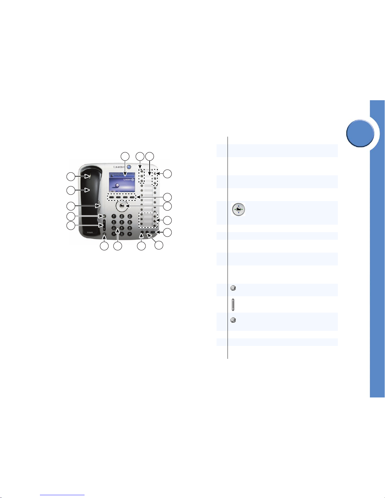
1 Phone screen serves as your phone “desktop.”
2
Intercom lines are assigned a 3-digit extension. Use these
lines for calls inside your company.
3
Button template lists your line button and feature button
assignments. You can print the button template from your
User Settings page.
4
Outside lines are assigned a 10-digit phone number. Use
these lines for calls outside your company.
5
Softkeys provide access to tabs and calling options on the
phone screen.
6
4-way navigation dial with center select
button allows you to scroll through and
activate items on the phone screen, select and
place calls, and edit text on the screen.
7 Feature buttons provide access to special phone features.
8 Hold button puts a call on hold.
9
Display button displays the function of each line and
feature button.
10
Cancel button cancels the current phone task and
displays the previous screen.
11
Phone key pad allows you to dial phone numbers, enter
numbers on the phone screen, and interact with voice mail
and Auto Attendant systems.
12
Microphone button mutes and unmutes the
microphone.
13
Vol ume control adjusts the volume for the handset
speaker and the speakerphone.
14
Speakerphone button enables hands-free
calling via the speakerphone or headset. This button
turns green when the speakerphone is on.
15 Phone speaker provides hands-free listening.
16 Handset
17
Voice message indicator turns red when you have a voice
mail message.
Page 22
15
Chapter 1: Welcome to Linksys One
Linksys One IP Phones
Linksys One Communications Solution
Chapter
1
Graphical Phone Screen Interface
The PHM1200 features a color phone screen that provides access to calling functions, call
history, and voice mail settings. The top of the phone screen displays the current date and
time; the bottom of the phone screen displays the Calls and Tas ks tabs that provide access to
calling functions and phone settings. All calling functions can be performed from the phone
screen. Simply select the Calls tab to place and handle calls, and select the Tas ks tab to view
call history, view the button template, and access voice mail settings.
Linksys One IP Phone (Rear Panel)
10/100 SW 10/100 PC
DC48V
144879
1 2 3
45
1
10/100SW Port provides an RJ-45 Fast Ethernet
connection to the SVR3000. It accepts IEEE PoE,
allowing the PHM1200 to be fully powered without an
external power adapter.
2
10/100PC Port provides an RJ-45 Fast Ethernet
connection to a desktop PC.
3
Headset port provides a connection to an approved
headset. For a listing of approved headsets, see
www.cisco.getheadsets.com.
4
Handset port provides a connection to the phone
handset.
5
Power Port connects to an optional AC/DC power
adapter in case you choose not to use POE to power the
PHM1200.
Page 23

Chapter
1
16
Chapter 1: Welcome to Linksys One
Linksys One Voice Gateways
Linksys One Communications Solution
Linksys One Voice Gateways
The Linksys One Communications Solution offers three voice gateways:
• Linksys One VGA2000 Analog Voice Gateway
• Linksys One VGA2100 Analog Voice Gateway
• Linksys One VGA2200 Analog Voice Gateway
Linksys One VGA2000 Analog Voice Gateway
The VGA2000 is an analog gateway that connects legacy analog fax machines or phones
to the Linksys One solution. In addition it provides a local connection to the public telephone
network for normal or emergency services calls.
The VGA2000 connects to any LAN port on the Services Router. Software running on the
VGA2000 interacts with provisioning, management and security software hosted on the
Services Router. This interaction provides a simple, one-step installation and access to webadministered management features.
Emergency Services (911)
The VGA2000 has one trunk-side FXO port (LINE port) for connecting to the public
telephone network and one station-side FXS port (PHONE port) for connecting to an analog
phone or fax machine. All emergency services calls are sent out the FXO LINE port. The
VGA2000 draws power from the FXO trunk so in the event that the Services Router (or the
external power-supply) fails, you can still make emergency services calls.
IMPORTANT: The VGA2000 Voice
Gateway does not accept inbound calls
from the public telephone network;
therefore, callbacks on that line from the
911 operator (PSAP) are not supported.
Linksys One VGA2000 Voice Gateway
Page 24

17
Chapter 1: Welcome to Linksys One
Linksys One Voice Gateways
Linksys One Communications Solution
Chapter
1
Fax Capability
You can use the FXS (PHONE) port on the VGA2000 to connect a fax machine. Simply
connect your fax machine to this port and then connect the LINE port to the public telephone
network for your office. You can dedicate a phone line for sending and receiving faxes. See
"Assigning a Phone Line to an FXS Port” in Chapter 5: Administering the CPE.
VGA2000 Hardware Features
The VGA2000 provides the following hardware features:
•64 MB RAM
•32 MB Flash
• One-each FXO/FXS port (RJ-11 jacks)
• FXO/FXS fail over
• Wall mountable and stackable
• US/Canada certifications (e.g. EMI.)
• Optional External Power supply (48V DC, 3.3V, AC-DC adaptor)
• One RJ-45 modular jack for a 10/100 Ethernet port providing LAN-to-Services
Router function with the ability to negotiate and accept IEEE POE from the Services
Router.
• One external USB 1.1 port.
• Six front panel indicators (FXS port status, FXO port status, Link status, Link activity,
On/Off status, Proxy indicator)
Page 25
Chapter
1
18
Chapter 1: Welcome to Linksys One
Linksys One Voice Gateways
Linksys One Communications Solution
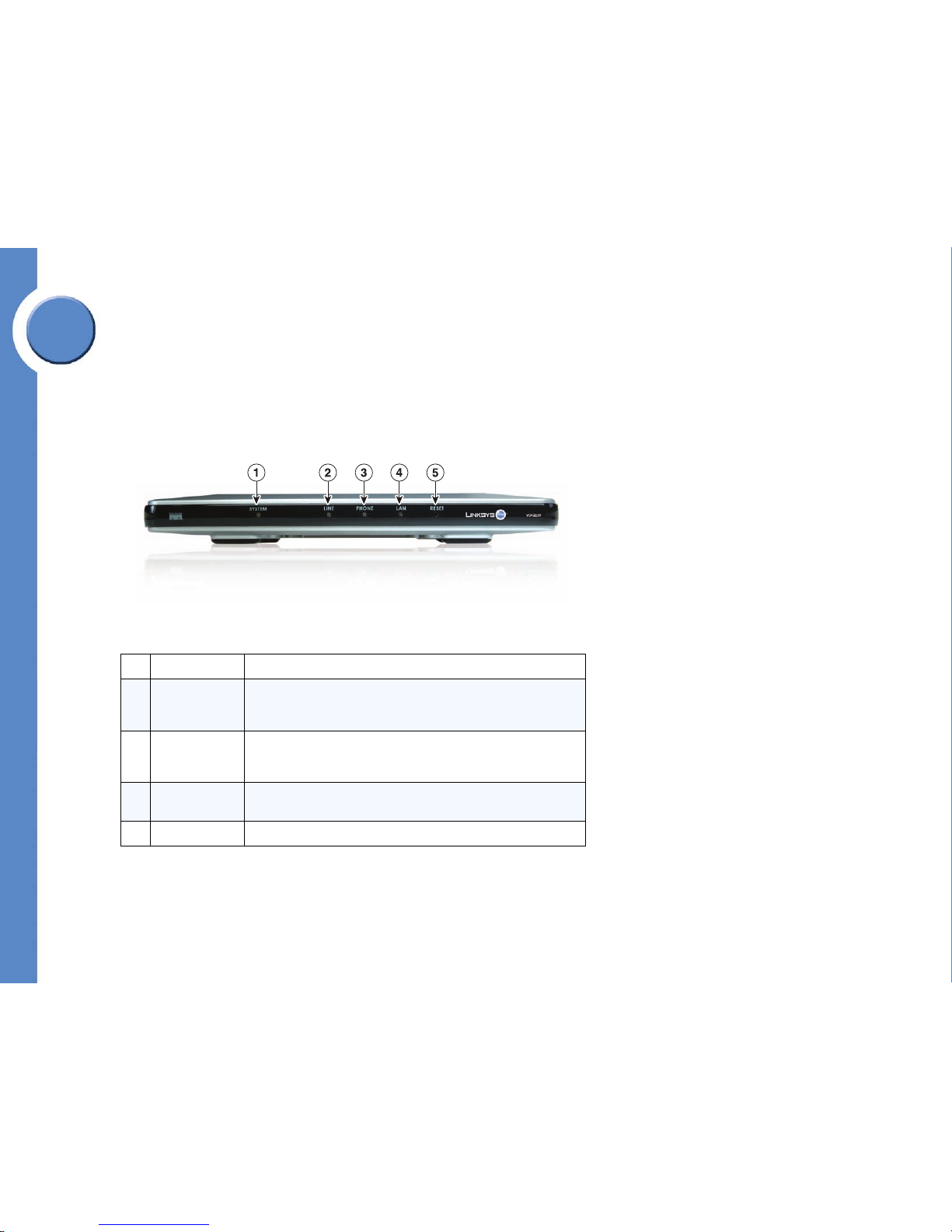
VGA2000 Voice Gateway Front Panel
1 SYSTEM LED Green when up; red when down.
2 LINE LED
Green when the VGA2000 is connected to the public telephone network
and the line is available. Flashing green when the line is in use. Red
when the line is not registered with the Services Router.
3 PHONE LED
Green when the port is available; flashing green when the port is in use.
Red when an intercom or phone line is not registered with the Services
Router.
4 LAN LED
Green/green flash when the VGA2000 is connected to the Services
Router. RED when there is no LAN connection available.
5 RESET LED Flashes red when the VGA2000 is resetting
VGA2000 Software Services
Operating System
Montavista Linux w/ kernel
2.4.17
Services
Scheduler, File System,
Memory Management
IP Services
RTP / RTCP
DHCP Client for Automated IP
Configuration
TFTP for Field Software
Upgrade
IEEE 802.1 p/q
IEEE 802.1 D
IPv4
UDP Support
TCP Support
DNS Support
IGMP Support
Security Services Certs, AES
USB USB 1.1 Host driver
Device Drivers LED status indicators
DAA/SLIC (SPI/PCM)
Telephony Feature
List
Voice codec: G.711,
Line Echo Cancellation
Voice Activity Detection
Comfort Noise Generation
DTMF and Ring Tone
Generation
Caller ID detection /
generation
DTMF relay
Page 26
19
Chapter 1: Welcome to Linksys One
Linksys One Voice Gateways
Linksys One Communications Solution
Chapter
1
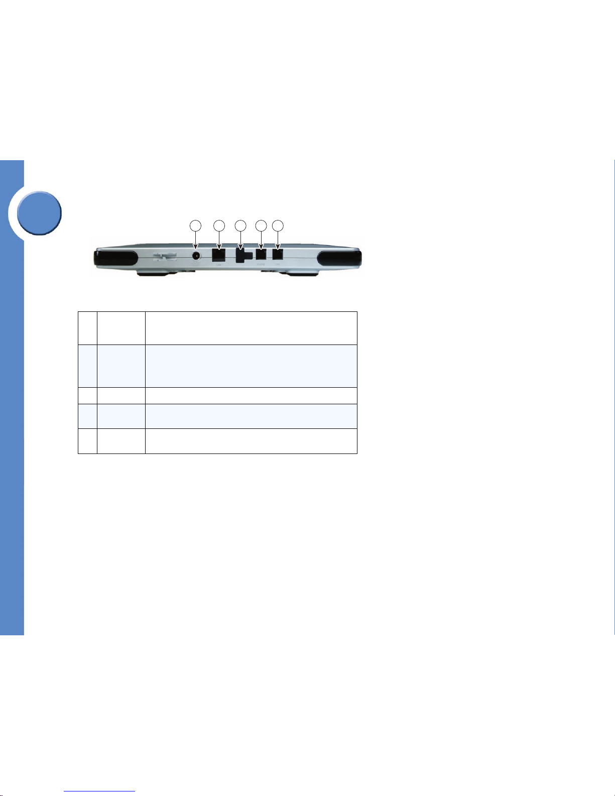
VGA2000 Voice Gateway Rear Panel
1 POWER Port An AC/DC power adapter port connects an optional AC/DC power
adapter in the event you choose not to power the VGA2000 over the
Ethernet.
2 LAN Port A dual 10/1000 Ethernet port provides an RJ-45 Fast Ethernet
connection to the Services Router. It receives 802.3af power,
allowing the VGA2000 to be fully powered without an external
power adapter.
3 USB Port Not used
4 PHONE Port The FXS port provides an RJ-11 connection to an analog phone or
fax machine.
5 LINE Port The FXO port provides an RJ-11 connection to the public telephone
network.
12345
144878
Page 27

Chapter
1
20
Chapter 1: Welcome to Linksys One
Linksys One Voice Gateways
Linksys One Communications Solution
Linksys One VGA2100 Analog Voice Gateway
The Linksys One VGA2100 is an analog voice gateway that provides a local connection to
the public telephone network for normal or emergency services calls. The VGA2100 offers:
• Simple, automated installation with Linksys One Services Routers
• Three simultaneous analog connections to the public telephone network
• IEEE 802.3af PoE from the connected Linksys One switch port
• Integrated call processing features with security, management, QoS
About the VGA2100...
The Linksys One VGA2100 analog voice gateway provides three FXO ports to connect
public telephone network lines to the Linksys One solution. When more than three
simultaneous calls are required, additional VGA2100 analog voice gateways can be added
to the solution. The 10/100 Ethernet port connects the VGA2100 to the site and enables
Voice over Internet Protocol (VoIP) calls. This port also accepts IEEE PoE (802.3af) and fully
powers the voice gateway and additionally provides quality of service for each call (DSCP).
Software running on the VGA2100 interacts with provisioning, management, and security
software on the site's Services Router and interacts further upstream to the service provider.
This interaction provides a simple, one-step installation and access to web-administered
features for the administrator and users.
VGA2100 Hardware Features
The VGA2100 provides the following hardware features:
•64 MB RAM
•32 MB Flash
• Three FXO ports (RJ-11 jacks)
• Wall mountable and stackable
• US/Canada certifications (e.g. EMI.)
• Optional Power supply - 48V DC-> 3.3V, AC-DC adaptor
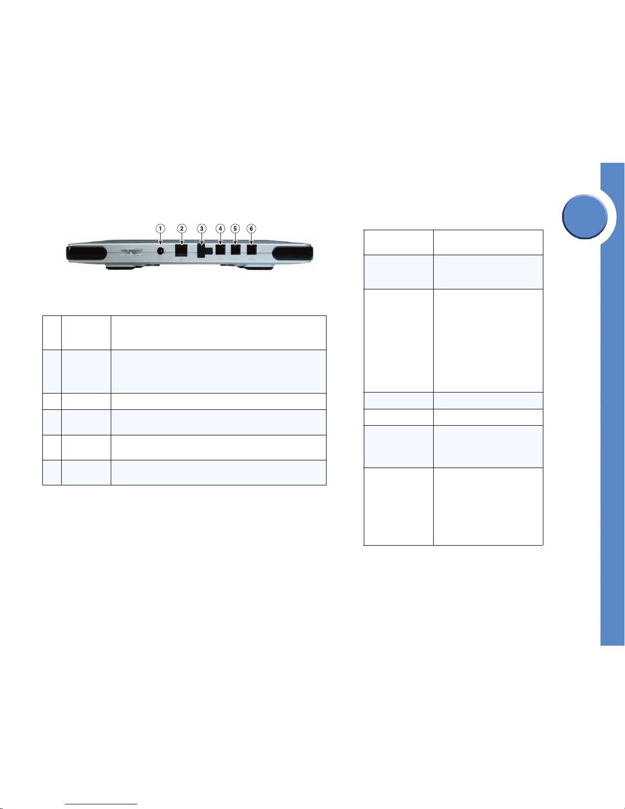
Linksys One VGA2100 Voice Gateway
Page 28
21
Chapter 1: Welcome to Linksys One
Linksys One Voice Gateways
Linksys One Communications Solution
Chapter
1
• One RJ-45 modular jack for 10/100 Ethernet port for LAN connection to router
function with ability to negotiate and accept IEEE POE from switch
• One external USB 1.1 port.
• Five front panel indicators (3 FXO port status, Link status/Link activity, Power On/
Off status, System indicator)
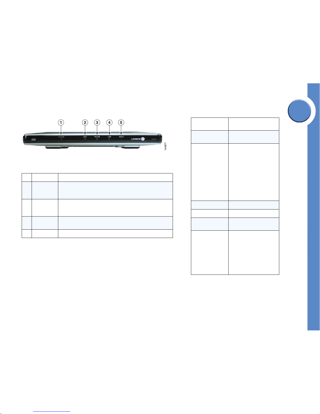
Linksys One VGA2100 Front Panel
1 SYSTEM LED Green when up; red when down.
2
LINE LEDs
(LINE 1, LINE 2,
LINE 3)
Green when the associated port is connected to the public telephone
network and the line is available. Flashing green when the line is in use.
Red when the line is not registered with the Services Router.
3 PHONE LED
Green when the port is available; flashing green when the port is in use.
Red when an intercom or phone line is not registered with the Services
Router.
4 LAN LED
Green/green flash when the VGA2100 is connected to the Services
Router. RED when there is no LAN connection available.
5 RESET LED Flashes red when the VGA2100 is resetting
Page 29
Chapter
1
22
Chapter 1: Welcome to Linksys One
Linksys One Voice Gateways
Linksys One Communications Solution
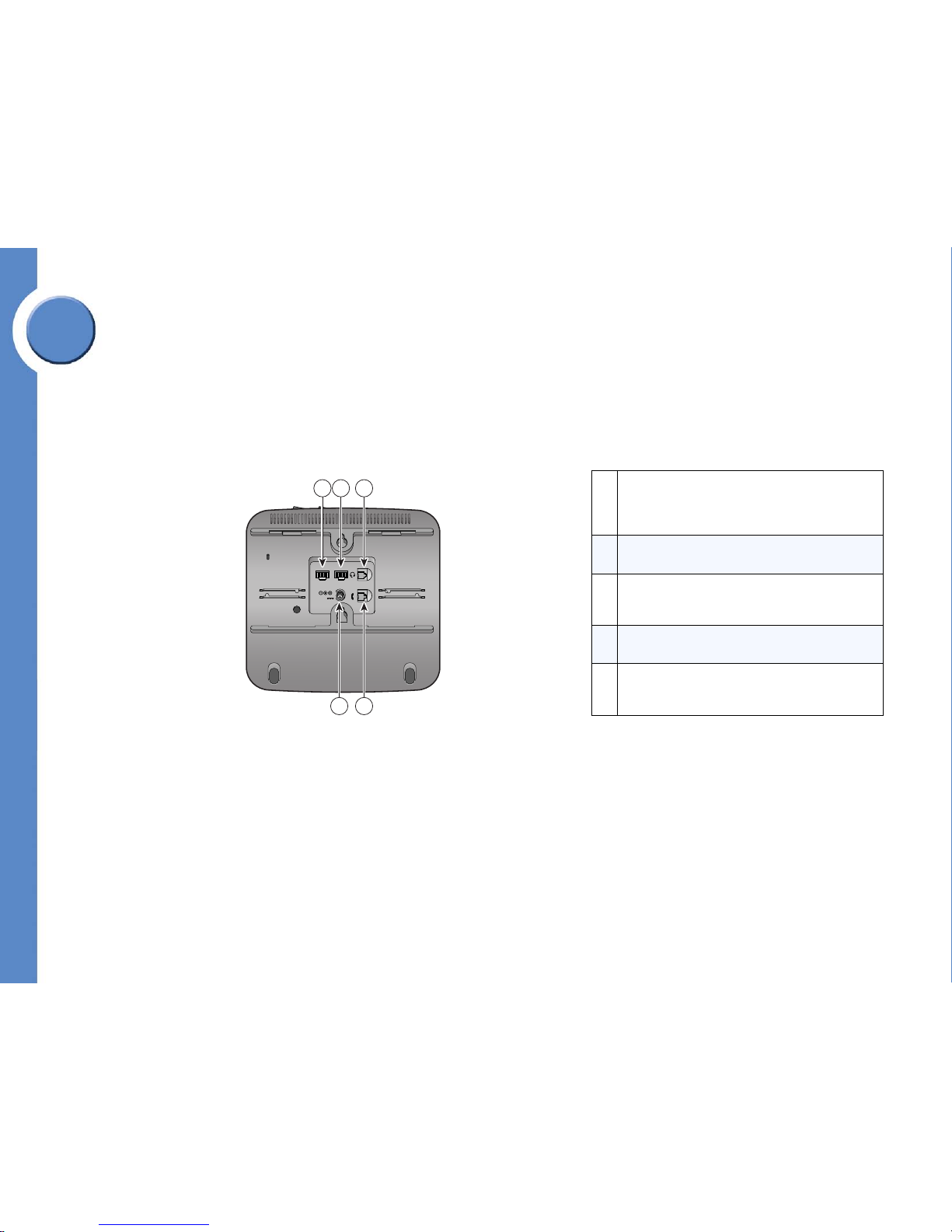
Linksys One VGA2100 Rear Panel
1 POWER Port An AC/DC power adapter port connects an optional AC/DC power
adapter in the event you choose not to power the VGA2000 over the
Ethernet.
2 LAN Port A dual 10/1000 Ethernet port provides an RJ-45 Fast Ethernet
connection to the Services Router. It receives 802.3af power,
allowing the VGA2000 to be fully powered without an external
power adapter.
3 USB Port Not used
4 LINE Port The FXO port provides an RJ-11 connection to the public telephone
network.
5 LINE Port The FXO port provides an RJ-11 connection to the public telephone
network.
6 LINE Port The FXO port provides an RJ-11 connection to the public telephone
network.
VGA2100 Software Services
Operating System
Montavista Linux w/ kernel
2.4.17
Services
Scheduler,
File System,
Memory Management
IP Services
RTP / RTCP
DHCP client for automated IP
Configuration
TFTP for field software upgrade
IEEE 802.1 p/q
IEEE 802.1 D
IPv4
UDP Support
TCP Support
DNS Support
IGMP Support
Security Services Certs, AES
USB USB 1.1 Host driver
Device Drivers
LED status indicators
DAA/SLIC (SPI/PCM)
USB 1.1 Host driver
10/100 Ethernet LAN drive
Te le ph ony Fe a tu re
List
SIP user agent, RTP/RTCP
Voice codec: G.711
Line Echo Cancellation
Voice Activity Detection
Comfort Noise Generation
DTMF and Ring Tone Generation
Caller ID detection / generation
DTMF relay
Page 30

23
Chapter 1: Welcome to Linksys One
Linksys One Voice Gateways
Linksys One Communications Solution
Chapter
1
Linksys One VGA2200 Analog Voice Gateway
The Linksys One VGA2200 is an analog voice station gateway that provides connectivity
with older voice devices like fax machines and analog phones. The Services Router is the
core of your network, and must be present to facilitate all Linksys One solution
configurations. The VGA2200 provides:
• Simple, automated installation with Linksys One Services Routers
• Two simultaneous analog connections to fax machines or analog phone stations
• IEEE 802.3af PoE from a connected Linksys One switch port
• Integrated call processing features with security, management, QoS
About the VGA2200...
The VGA2200 provides two FXS ports to connect analog stations to the Linksys One
solution. When more than two-station support is required, additional VGA2200 analog
voice gateways can be added to the solution. The 10/100 Ethernet port connects the
VGA2200 to the site and enables Voice over Internet Protocol (VoIP) calls. This port also
accepts IEEE PoE (802.3af) and fully powers the voice gateway and additionally provides
quality of service for each call (DSCP).
Software running on the VGA2200 interacts with provisioning, management, and security
software on the site’s Services Router and interacts further upstream to the service provider.
This interaction provides a simple, one-step installation and access to web-administered
features for the administrator and users.
Linksys One VGA2200 Voice Gateway
Page 31

Chapter
1
24
Chapter 1: Welcome to Linksys One
Linksys One Voice Gateways
Linksys One Communications Solution
VGA2200 Hardware Features
•64 MB RAM
•32 MB Flash
• Two FXS ports (RJ11 jacks)
• Wall mountable
• US/Canada certifications (e.g. EMI.)
• Optional power supply - 48V DC-> 3.3V, AC-DC adaptor
• One RJ-45 modular jack for 10/100 Ethernet port for LAN connection to router
function with ability to negotiate and accept IEEE POE from switch
• One external USB 1.1 port.
• Four front panel indicators (FXS port status x 2, Link status, On/Off status)
VGA2200 Software Services
Operating System
Montavista Linux w/ kernel
2.4.17
Services
Scheduler,
File System,
Memory Management
IP Services
RTP / RTCP
DHCP client for automated IP
configuration
TFTP for field software upgrade
IEEE 802.1 p/q
IEEE 802.1 D
IPv4
UDP Support
TCP Support
DNS Support
IGMP Support
Security Services Certs, AES
USB USB 1.1 Host driver
Device Drivers LED status indicators
DAA/SLIC (SPI/PCM)
Telephony Feature
List
Voice codec: G.711
Voice Activity Detection
Comfort Noise Generation
DTMF and Ring Tone generation
Caller ID detection /generation
DTMF relay
Page 32

25
Chapter 1: Welcome to Linksys One
Linksys One Voice Gateways
Linksys One Communications Solution
Chapter
1
Linksys One VGA2200 Front Panel
1 PHONE 1
Green when the associated port is connected to the public telephone
network and the line is available. Flashing green when the line is in use.
Red when the line is not registered with the Services Router.
2 PHONE 2
Green when the associated port is connected to the public telephone
network and the line is available. Flashing green when the line is in use.
Red when the line is not registered with the Services Router.
3 LAN LED
FXS LED, Red/Green. Flashes green when the VGA2200 is connected to
the Services Router and there is data activity. RED when there is no LAN
connection available.
4 SYSTEM
Green when up; red when down. Flashes red when the VGA2200 is
resetting
Page 33

Chapter
1
26
Chapter 1: Welcome to Linksys One
Linksys One Voice Gateways
Linksys One Communications Solution
Linksys One VGA2200 Rear Panel
1 POWER Port An AC/DC power adapter port connects an optional AC/DC power
adapter in the event you choose not to power the VGA2000 over the
Ethernet.
2 LAN Port A dual 10/1000 Ethernet port provides an RJ-45 Fast Ethernet
connection to the Services Router. It receives 802.3af power, allowing
the VGA2000 to be fully powered without an external power adapter.
3 PHONE Port The FXS port provides an RJ-11 connection to an analog phone or fax
machine.
4 PHONE Port The FXS port provides an RJ-11 connection to an analog phone or fax
machine.
5 USB Port Not used
180389
12 345
Page 34

27
Chapter 2: Start Here!
Linksys One Communications Solution
Chapter
2
Start Here!
This section provides a high-level summary of the steps for deploying the Linksys One
Customer Premises Equipment (CPE). Each step includes a link to where you can find
more information in this guide about performing that step..
Step 1: Prepare for Installation.
Prior to installing the Linksys One CPE, gather information about the customer’s site so that
you can successfully deploy the Linksys One communications solution.
See Chapter 3, "Preparing for Installation”. See also Appendix A for a guide to help you
gather customer contact information and other information about the customer site that you’ll
need to deploy the Linksys One Solution.
Step 2: Provision Your Customer on the Service Node.
Once you’ve gathered information about your customer’s site, establish this customer on the
Service Node.
See "Establishing a Customer on the Service Node” in Chapter 3.
Page 35

Chapter
2
28
Chapter 2: Start Here!
Linksys One Communications Solution
Step 3: Install the Services Router.
Connect the Services Router to the WAN and then connect it to power. See the "Installing the
Services Router” section in Chapter 4. If you are installing the Services Router in a cascade
(two Services Routers) you need to connect the two Services Routers together before you
connect them to the WAN or to power. See the "Installing Two Services Routers” section in
Chapter 4.
Step 4: Connect One Phone to the Services Router.
Connect the first phone to the Services Router. This phone is called the “handshake phone”
and is the phone you use to make a “handshake” with the Service Node.
See the "Connecting the Handshake Phone” in Chapter 4.
Step 5: Observe the Phone Boot Process.
Once you plug in the handshake phone, the boot process begins. As the phone starts up,
you will see icons and/or messages indicating the phone’s boot status. Phones which have
been previously configured should boot in 1-3 minutes while new phones (or phones which
are upgrading their firmware images) may take up to 15 minutes to boot.
See the "Verify Installation” in Chapter 4.
Step 6: Enter Handshake Information.
Once the phone receives the configuration file and software updates, you are prompted for
the following handshake information:
• Service Provider ID
• Customer Login
• Password
This information is generated when you provision the customer on the Service Node. See the
"Establishing a Customer on the Service Node” section in Chapter 3.
144548
PHM1200 IP Phone
137056
Page 36

29
Chapter 2: Start Here!
Linksys One Communications Solution
Chapter
2
Once you enter the handshake information, the Services Router establishes a handshake
back to the Service Node and verifies that customer address and site information are
correct. When verification is complete, the Services Router downloads configuration
information for the site, and the phone displays the Handshake Complete screen.
Step 7: Connect Additional Phones.
When the handshake phone displays Plug in Remaining Phones, connect additional phones
to the Services Router. As you plug in each phone, the handshake phone adds the phone’s
MAC address to the list displayed on the phone screen. The Services Router provides images
and configurations to each phone. When a phone has received its configuration, you’ll see
a check mark next to its MAC address in the list of phones on the handshake phone screen.
After the handshake is complete and you have installed all phones, each phone will reboot
and come up in operational mode.
See the ”Installing Additional Phones” section on page 62.
Step 8: Add Linksys One Voice Gateways.
The Linksys One Voice Gateways (VGA2000, VGA2100, and VGA2200) connect legacy
analog FAX machines or phones to the Linksys One network. In addition, these analog voice
gateways provide a local connection to the public telephone network for normal or
emergency services calls. You can connect an analog phone to the FXS port on the Voice
Gateway so that users can place emergency services calls even if the power fails.
Alternately, you can use the Voice Gateway with a fax machine.
See the ”Adding a Linksys One Voice Gateway to the Network” section on page 64.
IMPORTANT: When you add a Voice
Gateway to your network, you’ll need to
restart the Services Router.
144611
D
C
4
8
V
D
C
48V
P
H
O
N
E
!
P
H
O
N
E
2
LAN
140030
Phone 2
Phone 1
Page 37

Chapter
2
30
Chapter 2: Start Here!
Linksys One Communications Solution
Step 9: Customize the Phone System.
Although most system settings are already set for you, you can use the simple Web-based
Administration Editor to customize settings for your customer’s site, users, and network.
See Chapter 5: "Administering the Phone System”.
Step 10: Provide Information to Phone Users.
Each phone comes with a Quick Reference Card that includes brief procedures for the most
commonly used features on the phone. You’ll want to leave the quick reference card on each
user’s desk when you install their phone.
See Chapter 6: ”Using Your Phone” section on page 117 for details on how to use the phone
features.
Step 11: Administer the Network.
Once the phone system is up and running, you can administer your customer’s network
locally or remotely using the Web-based Administration Editor. You can easily add and
delete phones and change phone assignments for your customer’s site and users. Plus, you
can view network and phone status. Any changes you make to network devices
automatically take effect during the next system maintenance window. You can also choose
to make them take affect immediately.
See Chapter 7: ”Administering the Network” section on page 147.
Step 12: Troubleshoot Problems.
The Linksys One Communications Solution is designed to eliminate the installation and
maintenance complexities usually associated with the Internet and Voice Over IP (VoIP)
equipment. In the event you need to troubleshoot problems, see Chapter 7,
”Troubleshooting” section on page 169.
Hosted Service
Provi der
Broadband
Access
ISP(s)
PSTN
Customer
Premises
HSP
New CPE image
Loaded on SN
Your Code
Needs
Upgrading
My Code
vers io n is
1.x
Weekly
Maintenance
Win dow
Code Down loaded to CPE
Page 38

31
Chapter 3: Preparing for Installation
Preparing the Site
Linksys One Communications Solution
Chapter
3
Preparing for Installation
This section describes how to plan for and deploy Linksys One Customer Premises Equipment
(CPE). Use this section as an aid in gathering the critical customer information you need to
successfully deploy the physical components that comprise the Linksys One Communications
Solution and establish customers on the system.
• ”Preparing the Site” section on page 31
• ”Establishing a Customer on the Service Node” section on page 49
See Appendix A, “Customer Site Survey,” for a customer site survey that you can use to
obtain the information needed for planning installation and deployment of Linksys One CPE.
Preparing the Site
Before installing your CPE equipment, consider the following:
• Environmental conditions for maintaining normal operation. See “Site Environmental
Considerations” on page 32.
• Power and cabling requirements. See “Services Router SVR3000 Electrical
Requirements” on page 33 and “Cabling Requirements” on page 37.
• Equipment needed for installation. See “Installation Tools and Equipment” on
page 37.
• Equipment mounting and layout. See “Services Router Mounting Specifications” on
page 37 and “Equipment Layout for Installation” on page 38.
• Number of phones, phone lines, and voice gateways required. See “CPE Capacity
Planning” on page 39.
• WAN bandwidth, network connectivity, IP addressing requirements and firewall
considerations. See “Network Requirements” on page 40.
• Device and line assignment distribution. See “Device and Line Assignment
Guidelines” on page 45.
Page 39

Chapter
3
32
Chapter 3: Preparing for Installation
Preparing the Site
Linksys One Communications Solution
Site Environmental Considerations
With a little environmental planning up front, you can help avoid equipment failures and
reduce the possibility of environmentally-related network shutdowns. You should plan the site
configuration and prepare the customer’s site before installation. The location of your wiring
room is an extremely important consideration for proper operation of your Linksys One
network. Equipment placed too close together, inadequate ventilation, and inaccessible
panels can cause malfunctions and shutdowns, and can make maintenance difficult. Plan for
access to both front and rear panels of the router.
Air Circulation
On the Services Router, air flows in to the cooling intake vents on the left side of the chassis
and is exhausted out the right side vents via the fans. To ensure there is adequate air flow,
allow at least 3 inches (75 mm) of unobstructed space on all sides of the Services Router, as
shown below.
CPE Environmental Specifications
Operating
Te mp er at ur e
32º F to 104º F (0º C to 40º C)
Storage
Te mp er at ur e
-40º F to 158º F (-40º C to 70º C)
Operating
Humidity
20 to 95% Non-Condensing
Storage
Humidity
5 to 90% Non-Condensing
133837
FansCooling intake
vents
Page 40

33
Chapter 3: Preparing for Installation
Preparing the Site
Linksys One Communications Solution
Chapter
3
When planning your site layout and equipment locations, observe the following precautions.
If you are currently experiencing shutdowns or an unusually high number of errors with your
existing equipment, these precautions can help you isolate the cause of the failures and
prevent future problems.
• Ensure that the room where your Services Router operates has adequate air
circulation. Electrical equipment generates heat. Without adequate air circulation,
ambient air temperature may not cool equipment to acceptable operating
temperatures.
• Ensure that the chassis cover on the Services Router is secure. The chassis is designed
to allow cooling air to flow through it via the cooling intake vents.
• Make sure the area around the chassis is free from obstructions with at least three
inches of clearance on all sides.
• Once you install the CPE, make sure that the site maintains an ambient temperature
of 0°C to +40 °C (+32 °F to +104 °F).
Services Router SVR3000 Electrical Requirements
For maximum protection, Linksys recommends that you connect the Linksys One CPE to a
conditioned power source or uninterruptible power supply (UPS). Electrical requirements for
the Linksys One CPE are shown below.
Services Router SVR3000 Electrical Requirements
AC Power 100-240V
Certification
UL (UL 60950), CSA (CSA 22.2), CE mark, EN60950
(2001)
Power Supply Output 456W
Step down voltages (from AC110V) DC48V (used for PoE), DC12V
Step down voltages (from DC12V) DC3.3V, DC2.5V, DC1.8V and DC1.3V
AC Frequency 50-60 Hz
Peak power 2400 VA
Page 41

Chapter
3
34
Chapter 3: Preparing for Installation
Preparing the Site
Linksys One Communications Solution
Voice Gateway Specifications
The tables in this section provide specifications for supported Linksys One voice gateways.
VGA2000 Analog Voice Gateway 1 FXS, 1 FXO Specifications
Description
Linksys One analog voice gateway with one line (FXO) port and one analog
station port (FXS) for analog phone or Fax.
Power
Accepts IEEE 802.3af PoE from connected Linksys One switch port.
Standards: IEEE 802.3, 802.3af, 802.1p
Certification UL (UL 60950), CSA (CSA 22.2), CE mark, EN60950 (2001)
Cabling Cat5 or better.
Dimensions
English: 12.01" (W) x 1.38" (H) x 6.50" (D)
Metric: 305 mm (W) x 35 mm (H) x 165 mm (D)
Unit Weight 1.1 lbs (0.5 kg)
Environmental
Operating Temperature: 32º F to 104º F (0º C to 40º C)
Storage Temperature: -40º F to 158º F (-40º C to 70º C)
Operating Humidity: 20 to 95% Non-Condensing
Storage Humidity: 5 to 90% Non-Condensing
Page 42

35
Chapter 3: Preparing for Installation
Preparing the Site
Linksys One Communications Solution
Chapter
3
VGA2100 Analog Voice Gateway 3 FXO Specifications
Description
Linksys One analog voice public network gateway with three FXO ports for
connecting the public voice network to the Linksys One solution for external call
connectivity.
Power
Accepts IEEE 802.3af PoE from connected Linksys One switch port.
Standards: IEEE 802.3, 802.3af, 802.1p
Certification UL (UL 60950), CSA (CSA 22.2), CE mark, EN60950 (2001)
Cabling Cat5 or better.
Dimensions
English: 12.01" (W) x 1.38" (H) x 6.50" (D)
Metric: 305 mm (W) x 35 mm (H) x 165 mm (D)
Unit Weight 1.15 lbs (0.52 kg)
Environmental
Operating Temperature: 32º F to 104º F (0º C to 40º C)
Storage Temperature: -40º F to 158º F (-40º C to 70º C)
Operating Humidity: 20 to 95% Non-Condensing
Storage Humidity: 5 to 90% Non-Condensing
Page 43

Chapter
3
36
Chapter 3: Preparing for Installation
Preparing the Site
Linksys One Communications Solution
VGA2200 Analog Voice Gateway 2 FXS Specifications
Description
Linksys One analog voice gateway with two station (FXS) ports for analog phones
or Fax.
Power
Accepts IEEE 802.3af PoE from connected Linksys One switch port.
Standards: IEEE 802.3, 802.3af, 802.1p
Certification UL (UL 60950), CSA (CSA 22.2), CE mark, EN60950 (2001)
Cabling Cat5 or better.
Dimensions
English: 6.25” (W) x 1.25” (H) x 5.50” (D)
Metric: 159 mm (W) x 32 mm (H) x 140 mm (D)
Unit Weight 0.70 lb (0.32 kg)
Environmental
Operating Temperature: 32º F to 104º F (0º C to 40º C)
Storage Temperature: -40º F to 158º F (-40º C to 70º C)
Operating Humidity: 20 to 95% Non-Condensing
Storage Humidity: 5 to 90% Non-Condensing
Page 44

37
Chapter 3: Preparing for Installation
Preparing the Site
Linksys One Communications Solution
Chapter
3
Cabling Requirements
Use Category 5 cables to connect the Linksys One CPE to IP phone runs. The cables should
meet the cabling standard defined in EIA/TIA-568B.
Installation Tools and Equipment
For a simple desktop or shelf installation, you may not need any tools.
The following tools may be useful for installing the CPE:
• No. 2 Phillips screwdriver
• 3/16-in. flat-blade screwdriver (for split shelf configurations)
• Tape measure (optional)
Services Router Mounting Specifications
The Services Router requires access to the front and rear panels.
Rackmount
Rack mounting specifications for the SVR3000 are listed below.
SVR3000 Rack Mounting Specifications
Mounting 19” rackmount or tabletop
Rack Units 2
Dimensions 12.09" x 11.77” x 1.38" (307 mm x 299 mm x 35 mm)
Unit Weight 9.11 lbs. (4.13 kg)
Services Router Shipping Dimensions
The shipping box for the Services Router
SVR3000 measures 8” H x 21.5” W x 19.5” D.
Services Router Placement Options
The Services Router can be placed on a desktop,
installed in a rack or mounted on the wall.
Page 45

Chapter
3
38
Chapter 3: Preparing for Installation
Preparing the Site
Linksys One Communications Solution
Equipment Layout for Installation
Here’s the recommended CPE equipment installation and zone layout for the Services Router.
Page 46

39
Chapter 3: Preparing for Installation
Preparing the Site
Linksys One Communications Solution
Chapter
3
CPE Capacity Planning
Use the information in the following table to plan CPE capacity at the customer site.
Devices, Lines, Bandwidth
Quantity
Planning Notes
PSTN for External Calls HSP (Internet) for External Calls
SVR3000 Services Router 1 (required)
1 (optional) cascaded SVR3000
1 (required)
1 (optional) cascaded SVR3000
One (1) additional Services Router can be
connected to the master Services Router as a
cascaded switch for additional device capacity.
Broadband connection
speed
Minimum recommended broadband
connection speed is 768 Kbps (CPE
firmware image download timeouts
are possible at lower connection
speeds).
Minimum recommended broadband
connection speed is 768 Kbps (upload and
download).
See “Bandwidth Requirements” on
page 41.
When establishing the customer on the Service
Node, select the broadband connection speed
that most closely matches the customer’s
connection speed.
Number of outside lines Up to 14 FXO lines, using any
combination of supported voice
gateways with FXO ports.
Up to 14 virtual ITSP trunk lines for
external calls, depending on the
bandwidth at the customer site.
See “Device and Line Assignment Guidelines”
on page 45 for information about device and
line configuration.
VGA2000 Voice Gateway
(1FXS /1FXO port)
Optional. Optional.
Refer to the ”Emergency Services (911)
Calling” section on page 48 for
information on using a VGA2000 to route
emergency services calls.
The VGA2000 must be connected to a LAN port
on the Services Router.
VGA2100 Voice Gateway
(3 FXO ports)
Up to 12 FXO lines per site, using any
combination of supported voice
gateways with FXO ports.
Optional
The current release does not support a
mixture of PSTN and HSP for external
calling.
The VGA2100 must be connected to a LAN port
on the Services Router.
VGA2200 Voice Gateway
(2 FXS ports)
Optional.
The maximum number of VGA2200s
supported depends on the number of
available ports on the SVR3000.
Optional.
The maximum number supported depends
on the number of available ports on the
SVR3000.
The VGA2200 must be connected to a LAN port
on the Services Router.
Page 47

Chapter
3
40
Chapter 3: Preparing for Installation
Preparing the Site
Linksys One Communications Solution
Network Requirements
Here’s the recommended network requirements at the customer premises for the Linksys One
solution.
Broadband Access Connection Requirements
The following types of broadband access connections are supported at the customer
premises:
• Services Router (Ethernet) connected to a DSL bridge or cable modem
• Services Router (Ethernet) connected to an IP DSL switch
• Services Router (Ethernet) connected to a Cisco router
• Service Router (Ethernet) connected to Metro Ethernet service
Linksys One requires Quality of Service (QoS) to be provisioned on the uplink portion of the
broadband connection if calls will be routed through the HSP.
Access configurations are dependent on the handoff from the broadband access provider.
The following broadband deployment models are supported in the current release:
PHM1200 IP Phone Minimum of 1.
Maximum of 32 with cascaded
Services Router.
Subtract 1 from the maximum number
of phones for each voice gateway or
data device connected to a port on the
SVR30000.
Minimum of 1.
Maximum of 32 with cascaded Services
Router.
Subtract 1 from the maximum number of
phones for each voice gateway or data
device connected to a port on the
SVR30000.
The Services Router SVR3000 has 16 LAN
ports, which can support up to 16 PHM1200
phones. An additional 16 LAN ports for IP
phones can be provided by connecting another
SVR3000 to the master Services Router as a
cascaded switch.
Connecting data devices to phones does not
affect the number of phones.
Devices, Lines, Bandwidth
Quantity
Planning Notes
PSTN for External Calls HSP (Internet) for External Calls
Page 48

41
Chapter 3: Preparing for Installation
Preparing the Site
Linksys One Communications Solution
Chapter
3
• Single Ethernet to SVR3000. The public IP address is presented to the SVR3000.
• 802.1Q Ethernet. Single Ethernet with separate voice and data VLANs.
PPPoE is not currently supported.
Bandwidth Requirements
The minimum recommended broadband bandwidth for Linksys One is 768 Kbps (upload
and download). At speeds lower then 768 Kbps, CPE firmware image download may
timeout.
Customers routing calls through their Linksys One HSP should consider the available WAN
upload bandwidth when determining the number of lines to add.
For calls routed through the Internet, the available upload bandwidth determines the
maximum number of simultaneous calls a site can support. If the total amount of bandwidth
used for ITSP calls exceeds the total available upload bandwidth, voice quality is degraded
for all calls.
The approximate amount of bandwidth consumed per call varies by connection type:
• DSL — 106 Kbps per call
• T1/E1 with PPP — 82.8 Kbps per call.
• Ethernet — 81.2 Kbps per call.
For example, a minimum of 812 Kbps of upload bandwidth would be required to support
10 simultaneous calls over an Ethernet connection with acceptable voice quality.
IP Addressing Requirements
A public IP address is required for the Services Router WAN interface. This public IP address
may be assigned to the WAN1 port on the Services Router using DHCP (the default) or static
addressing. It is very important that the assigned address is not subjected to network address
translation by either the broadband access device or the service provider network.
The Services Router itself is a DHCP server on the LAN side. Connecting the Services Router
to a network which has an existing DHCP server might lead to unexpected IP assignments for
Page 49

Chapter
3
42
Chapter 3: Preparing for Installation
Preparing the Site
Linksys One Communications Solution
the data devices (IP phones are not affected). DHCP server settings on the Services Router
cannot be disabled.
Firewalls and the Services Router
For the current release, placing the Services Router behind a firewall is not a supported
configuration. However, if a firewall must co-exist with the Services Router at the customer
site, this section provides information about the ports and protocols that must be allowed
access.
Ideally, all traffic should be allowed in and out of the Services Router’s IP address, but the
following are mandatory:
• IP Protocol ID 50, for both inbound and outbound filters. Should be set to allow
Encapsulating Security Protocol (ESP) traffic to be forwarded
• IP Protocol ID 51, for both inbound and outbound filters. Should be set to allow
Authentication Header (AH) traffic to be forwarded
• UDP Port 500, for both inbound and outbound filters. Should be set to allow ISAKMP
traffic to be forwarded
• L2TP/IPSec traffic looks just like IPSec traffic on the wire. The firewall just has to
allow IKE (UDP 500) and IPSec ESP formatted packets (IP protocol = 50)
•ICMP
• HTTPS (Ports 51, 443 and 8443)
• For VoIP traffic to be transmitted correctly, you must open the UDP range from
16384-16483 (100 ports) (inbound and outbound).
The table on the following page lists these ports and protocols in more detail.
IMPORTANT: The address on the WAN
interface of the SVR3000 must be
public, and not behind a device that
performs Network Address Translation
(NAT).
Page 50

43
Chapter 3: Preparing for Installation
Preparing the Site
Linksys One Communications Solution
Chapter
3
Protocol/Port Description Used by Direction
Source Destination
IP Port IP Port Importance
ICMP ICMP Echo
Connectivity
check
Outbound SVR3000 n/a any n/a Critical
ICMP
ICMP Echo
Reply
Connectivity
check
Inbound any n/a SVR3000 n/a Critical
ICMP ICMP Echo
Nagios
(system
monitoring)
Inbound any n/a SVR3000 n/a Desirable
ICMP
ICMP Echo
Reply
Nagios
(system
monitoring)
Outbound SVR3000 n/a any n/a Desirable
UDP DNS Name resolution Outbound SVR3000 any any 53 Critical
UDP DNS Name resolution Inbound any 53 SVR3000 any Critical
UDP RTP VoIP audio Outbound SVR3000 16384 and up any any Critical
UDP RTP VoIP audio Inbound any any SVR3000 16384 and up Critical
UDP IKE SIP Signalling Outbound SVR3000 500 Service Node 500 Critical
UDP IKE SIP Signalling Inbound Service Node 500 SVR3000 500 Critical
Protocol 50 IPsec/ESP SIP Signalling Outbound SVR3000 n/a Service Node n/a Critical
Protocol 50 IPsec/ESP SIP Signalling Inbound Service Node n/a SVR3000 n/a Critical
TCP HTTPS
SVR3000
administration
Inbound any any SVR3000 51 Desirable
TCP HTTPS
Nagios
(system
monitoring)
Inbound any any SVR3000 8080 Desirable
Page 51

Chapter
3
44
Chapter 3: Preparing for Installation
Preparing the Site
Linksys One Communications Solution
IP Addressing Scheme and Subnets
The internal IP addressing scheme assigned to the CPE is based on the RFC 1918 private
addressing standard. The Services Router has a fixed private addressing scheme. Subnets
are assigned to the VLANs as shown in the following table, and each device in the subnet is
assigned the standard Class C mask of 255.255.255.0.
Quality of Service
The Services Router will automatically shape traffic to the available uplink bandwidth and
then prioritize and allocated bandwidth between the voice packets and data packets, within
the shaped bandwidth. Voice performance criteria used in Linksys One testing (without
service provider-induced delay) is as follows:
• <=1% Voice Packet loss
• Average Jitter <=10 ms
• Average one-way Delay <=100 ms
Additional Site Considerations
This section covers additional site considerations such as data device connections, fax and
modem connections, dial plan, and Emergency Service calling.
Data Device Connections
Each IP phone has an Ethernet port that can be used to attach a data device (such as a PC)
to the network.
Subnet Assignment VLAN Purpose
192.168.10.0 VLAN 10 Voice network
192.168.100.0 VLAN 100 Data network
192.168.101.0/24 DMZ DMZ subnet
192.168.50.0 VLAN 50 Management Network
Page 52

45
Chapter 3: Preparing for Installation
Preparing the Site
Linksys One Communications Solution
Chapter
3
Any of the unused LAN ports on the SVR3000 can also be used to attach data devices to the
network. All data devices attached to the Services Router or behind Linksys One IP phones
are placed on the data VLAN (VLAN100).
Fax and Modem Connections
For the current release, it is recommended that customers with high-usage or businesscritical fax machines or modems use a dedicated public telephone line for these devices.
Dial Plan
For the current release, the dial plan is provisioned from the Service Node to the SVR3000.
North American Numbering Plan (NANP) is supported, as well as International dialing. For
North America, 10-digit, 7-digit, or 10- and 7-digit dialing is supported.
Australia/New Zealand dial plan support is also provided.
A small number of dial plan options are configured when adding customers. Customers
using the North American Number Plan have the option to select 10-digit, 7-digit, or 10and 7-digit dialing and an area code for 7-digit dialing.
Site-to-site extension dialing is not supported in the current release.
Device and Line Assignment Guidelines
Use the guidelines in this section when planning device and line assignments for a customer
site.
Phones, line appearances, voice gateways and phone lines in a Linksys One system can
each be thought of as having a “device weight.” Device weights for each of these
components are shown in the following table.
Component Device Weight Description
Phone 1 A Linksys One phone
Line
appearance
1
Any external phone number (either ITSP or voice gateway)
assigned to a phone
Gateway 1 A Linksys One voice gateway
Phone line 1 A phone number assigned to an FXO port on a voice gateway
Page 53

Chapter
3
46
Chapter 3: Preparing for Installation
Preparing the Site
Linksys One Communications Solution
Devices and line assignments for a single Linksys One site must be configured so that the
total device weight for the entire system is less than or equal to 84. Poor system performance
or other system problems can occur when this limit is exceeded.
The following examples show how to calculate the total device weight for a site.
Example 1
In this example, the customer site has 20 phones, 1 voice gateway and 10 external ITSP line
numbers, which are configured as follows:
• 5 phones with 1 private line assigned to each phone
(5 phones + 5 line appearances = 10 device weights)
• 5 phones with 3 shared lines assigned to each phone
(5 phones + 15 line appearances = 20 device weights)
• 10 phones with 2 shared lines assigned to each phone
(10 phones + 20 line appearances = 30 device weights)
• 1 voice gateway with 1 phone line
(1 gateway + 1 phone line = 2 device weights)
The total system device weight for this configuration is 62, which is within the acceptable
range.
Page 54

47
Chapter 3: Preparing for Installation
Preparing the Site
Linksys One Communications Solution
Chapter
3
Example 2
In this example, the customer site has 12 phones, 2 voice gateway and 6 external PSTN line
numbers, which are configured as follows:
• 2 phones with 1 private line assigned to each phone
(2 phones +2 line appearances = 4 device weights)
• 10 phones with no lines assigned
(10 phones + no line appearances = 10 device weights).
In this scenario, all 6 phone lines are forwarded to the Auto Attendant for call
distribution.
• 2 gateways with 3 phone lines assigned to each gateway
(2 gateways + 6 phone lines = 8 device weights).
The total system device weight for this configuration is 22, which is within the acceptable
range.
Page 55

Chapter
3
48
Chapter 3: Preparing for Installation
Preparing the Site
Linksys One Communications Solution
Emergency Services (911) Calling
For customers routing calls through their Linksys One HSP, Emergency Services calls can be
routed through the FXO port on the VGA2000.
If the HSP supports Emergency Services calling (for example, E911 in North America),
Emergency Services calls can be routed through the ITSP.
An analog phone can be connected to the FXS port on the VGA2000 to support Emergency
Services calling in the event of a power outage.
Page 56

49
Chapter 3: Preparing for Installation
Establishing a Customer on the Service Node
Linksys One Communications Solution
Chapter
3
Establishing a Customer on the Service Node
Once you’ve prepared your customer’s site for installing the CPE equipment, you’ll need to
establish this customer on the Service Node.
Before You Begin
Make sure that you have the following information:
• HSP provisioning URL, user ID and password for accessing the Web-based
administration interface on the Service Node that hosts your customer’s accounts.
This information will be provided by your HSP.
• Customer site and contact information.
• WAN upload bandwidth and connection type for the site
• Whether the customer will be routing external calls through the PSTN or through
their Linksys One Hosted Service Provider (HSP).
Customers who will be routing external calls to the PSTN using their own telephony
service provider do not need to request phone numbers.
• How many phone numbers the customer will need. This is only required for
customers who are routing external calls through their Linksys One HSP.
Once you’ve completed the customer establishment process, the Service Node will create the
“handshake” information you need to get the phone system up and running.
NOTE: This section provides general instructions for establishing a
customer on the Service Node. Procedures and screens for your Linksys
One HSP may be different or your HSP may choose to perform these
steps themselves.
Contact your Linksys One HSP for specific information about establishing
customers on the Service Node.
Page 57

Chapter
3
50
Chapter 3: Preparing for Installation
Adding a Customer
Linksys One Communications Solution
Adding a Customer
1. Log in to the Service Node that hosts your customer’s accounts:
URL: https://adm.<brand>.com
User ID: <brand>.com
Password: *******
For example, if you are a brand administrator, your HSP’s brand name is “acmevox” and
the password is b1g5ecret, you would enter the following information:
URL: https://adm.acmevox.com
User ID: acmevox.com
Password: b1g5ecret
If you are an Agent, you will log in using your Agent ID and password. For example:
URL: https://adm.acmevox.com
User ID: jsmith.acmevox.com
Password: 5ecretAgent
2. If a Security Alert dialog is displayed, click Ye s to proceed.
3. Click Add Customer from the Shortcuts section on the Service Node Administration
Home page.
4. The Customer info page displays.
5. Under Customer Info, enter the following information for your customer. Required fields
are marked with a red asterisk (*).
General Information
• Business Name, Time Zone
• Agent Name (optional; this field is not displayed if you are logged in as an Agent.)
If Agents have been set up for handling groups of customers, select an agent from
the drop-down list. Agents can only view or modify information for the customers to
which they have been assigned. Otherwise, select None.If you are logged in as an
Agent, any customers you create will automatically be assigned to you.
Page 58

51
Chapter 3: Preparing for Installation
Adding a Customer
Linksys One Communications Solution
Chapter
3
Service Address
• Street address (city, state and postal code) for the business
Service Contact (optional)
• First name, last name and e-mail address of the Service Contact for the business.
Security Information (optional)
• Leave this field blank to have the system generate a 6-digit numeric password for the
Linksys One installation handshake, or
• Enter a 6-digit number for the password you want to use during the installation
handshake, for example, 123456, then retype the new password for verification.
6. Click Next to continue to the Services & Numbers page.
7. Under Services Requested, choose CPE template options for WAN upload speed,
connection type, calling plan, firmware source, and dial plan options:
• Broadband Upload—specifies the upload speed of the WAN connection at the
customer’s site. Available options range from 128 Kbps to 10 Mbps.
Select the speed that most closely matches the upload speed for the customer’s site.
• Broadband Type—specifies the broadband access type. Accept the default selection,
which is Ethernet DHCP and IPSEC.
• Calling Plan—choose Virtually Unlimited + Intl.
• Firmware Source (optional)—Select a firmware release group for this customer from
the drop-down menu. This setting determines which version of product firmware will
be downloaded to the customer’s CPE during the installation handshake.
You can accept the default setting, which is usually the default firmware release
group for this brand (recommended for most customers) or override the default
brand setting by selecting a different firmware release group.
When the firmware release associated with the selected group is updated on the
Service Node, the new version will be downloaded to the customer’s CPE during the
next Services Router maintenance window.
Page 59

Chapter
3
52
Chapter 3: Preparing for Installation
Adding a Customer
Linksys One Communications Solution
• Dialing Plan Digits—This field provides options for selecting the number of digits
used when dialing. Options vary, depending on the dial plan for the Service Node
that hosts the customer’s account. Customers using the North American Dial Plan can
select 7, 10, or 7 + 10 (7 and10 digit dialing).
• Area Code—For North American Dial Plan customers, if 7-digit dialing or 7- and
10-digit dialing is selected, this field is used to specify the 3-digit area code to be
used in conjunction with 7-digit dialing.
Options that apply to dial plans for other countries can also appear in this section.
8. The Number Allocation section should only be completed if the customer will be routing
external calls through their Linksys One HSP and will need E.164 phone numbers.
Skip this section if the customer will be routing external calls through the PSTN.
• Under Number Allocation, choose phone numbers for your customer’s site.
•Click Show Numbers to display the list of available phone numbers.
• Enter an area code or an area code plus an exchange to display only phone
numbers in that area code and/or exchange.
• To select a number, highlight the number in the Available Numbers list and use the
>> arrow button to move it to the Chosen Numbers list. Only one number at a time
can be selected.
• To remove a number from the Chosen Numbers list, highlight it and click the <<
arrow button.
• Continue adding numbers until you have all the numbers you need, up to a
maximum of 14 numbers. You must choose at least one phone number.
Consider the available WAN upload bandwidth when determining the number of
lines to add. For calls routed through the Internet, the available upload bandwidth
determines the maximum number of simultaneous calls a site can support. If the total
amount of bandwidth used for ITSP calls exceeds the total available upload
bandwidth, voice quality is degraded for all calls.
See “Bandwidth Requirements” on page 41 for bandwidth per call estimates.
Page 60

53
Chapter 3: Preparing for Installation
Adding a Customer
Linksys One Communications Solution
Chapter
3
9. Click Next to go to the Equipment page.
10. The Equipment page displays the quantity of SVR3000s for the site.
Currently this is always set to 1. You can still add a second SVR3000 to be used as a
cascaded switch for additional LAN ports.
11. Click Next to go to the Billing Info page.
12. On the Billing Info page:
• Enter a billing address or check Use Service Address.
• Enter a billing contact or check Use Service Contact.
13. Click Next to verify your selections.
14. If you need to make changes, use the Back and Next buttons at the bottom of the page
(do not use your Web browser’s Back button).
15. When you are satisfied with your selections, click Next to add the customer and create
the “handshake information.”
Page 61

Chapter
3
54
Chapter 3: Preparing for Installation
Adding a Customer
Linksys One Communications Solution
16. Print the customer’s configuration information from your Web browser.
17. Optionally, enter the e-mail address to which you want to send a copy of the
configuration information.
18. To e-mail a copy to the customer, check Send to Customer.
When this option is checked, the configuration information will be sent to the e-mail
address you entered for the Service Contact in the Customer Info section.
Page 62

55
Chapter 4: Installation
Installing the Services Router
Linksys One Communications Solution
Chapter
4
Installation
Quick installation instructions are included in the box with each Linksys One component.
This chapter provides more detailed procedures for installing and verifying the operation of
the Linksys One CPE components. Refer to the following procedures:
• ”Installing One Services Router” section on page 55
• ”Installing Two Services Routers” section on page 58
• ”Installing Linksys One Phones” section on page 60
• ”Adding Computers to the Network” section on page 63
• ”Adding a Linksys One Voice Gateway to the Network” section on page 64
Installing the Services Router
Depending on the number of ports you want to make available to users and devices, you
can install one or two Services Routers on your Linksys One network. The installation
procedures differ so be sure to follow the proper procedure.
• Installing One Services Router
• Installing Two Services Routers
Installing One Services Router
1. Unpack the Services Router and verify that the box contains the following components:
• SVR3000 - 16-Port 10/100 Services Router
• AC Power Cord
• Category 5e RJ-45 cable
• Rack Mounting Kit with brackets and hardware
• Wall Mounting Kit with brackets and hardware
System Requirements
• QoS-enabled broadband access with a
minimum data rate of 768 Kbps.
• Category 5 or better cabling
• The IP address on customer’s WAN must
be publicly addressable
• The SVR3000 power supply has two
outputs: 50V and 12V. The total power
budget should be (IEEE 802.3af Class 3) =
15 W x 16
140165
RJ-45
Page 63

Chapter
4
56
Chapter 4: Installation
Installing One Services Router
Linksys One Communications Solution
• USB flash memory key
• Quick Installation Guide
2. (Optional) Mount the Services Router on the wall or in a rack using the wall mounting
brackets or rack mounting brackets and instructions included in the box.
3. Insert the USB flash memory key into the USB port on the Services Router front panel.
1. Connect the Services Router to the WAN using the supplied Category 5e RJ-45 cable as
follows:
a. Plug one end of the supplied Category 5 RJ-45 to RJ-45 cable into the Ethernet port
on the Broadband Internet Access device (e.g. cable/DSL modem).
b. Plug the other end of the cable into the WAN Port labeled W1 (top port) on the
SVR3000. Verify that the green LED for WAN Port W1 is illuminated.
2. Connect the Services Router to power using the supplied power cable.
IMPORTANT: The USB flash memory key
is used for voice mail storage and must
be plugged in to the Services Router at
all times for proper operation.
IMPORTANT: Make sure you connect the
USB key to the SVR3000 prior to
powering it up.
USB
144552
USB
Insert the USB Memory Key
Internet
Internet
1144546
WAN
Connect the WAN port on the Ser vices Router to the
WAN port on your broadband device
NOTE: The SVR3000 will obtain an IP
address from the DHCP server in the
Broadband Access Provider’s network
or the broadband router terminating the
Wide Area network connection from the
Broadband Access Provider (BBA).
Page 64

57
Chapter 4: Installation
Installing One Services Router
Linksys One Communications Solution
Chapter
4
Verifyin g Your Service s Router Installation
Once the Services Router has fully booted:
1. Connect your PC to any LAN port on the SVR3000 with a Category 5 RJ-45 to RJ-45
cable, open a command prompt and type in “ipconfig” to verify that the SVR3000 has
provided a 192.168.x.x address to your PCs Ethernet port.
2. Verify the following LED behavior:
3. If the Services Router is not working, see Chapter 8: "Troubleshooting”
SYSTEM LED Solid green when the Services Router is operating
properly. Flashes between green and red in onesecond intervals to indicate that a new image is
loading. When in cascade mode, flashes in
intervals of five seconds green and one second
red.
LAN LED Green to indicate a device is connected that port.
WAN LED Flashes green when there is activity on the WAN
port.
144547
Connect the Services Router to power
Page 65

Chapter
4
58
Chapter 4: Installation
Installing Two Services Routers
Linksys One Communications Solution
Installing Two Services Routers
To increase the number of ports available to users and devices on your network, you can
stack or “cascade” two Services Routers. When you cascade two Services Routers, only the
“Master” has all functions enabled (i.e., router, DHCP and DNS Servers, SIP Proxy, Image
and Configuration Servers). The downstream Services Routers in the stack are configured as
only Ethernet switches; all other functions, including WAN ports, are disabled.
Here’s how to cascade two Services Routers:
1. Mount the Services Routers in a rack using the rack mounting brackets and instructions
included in the box.
2. Insert the USB flash memory key into the USB port on the front panel of each Services
Router.
3. Connect the CASCADE ports on each Services Router in a daisy chain fashion using the
supplied Category 5e RJ-45 cable..
4. Designate one of the Services Routers in the stack as the “Master.” The other Services
Router is referred to as the “downstream” Services Router.
IMPORTANT: It is very important that
you precisely follow the documented
procedure for configuring the Services
Router as a cascade. Failure to do so
will result in the system becoming
unusable.When installing two Services
Routers on the network, you MUST
connect/cascade the two Services
Routers before connecting any phones.
IMPORTANT: Make sure you connect the
USB key to the SVR3000 prior to
powering it up.
144555
USB
USB
USB
Insert USB Keys
Connect the Master Services Router to the WAN
Internet
Internet
144550
CASCADE WAN
C1 W1
CASCADE WAN
C1 W1
144549
Connect the Cascade Ports
Page 66

59
Chapter 4: Installation
Installing Two Services Routers
Linksys One Communications Solution
Chapter
4
5. Connect the Master Services Router to the WAN using the supplied Category 5e RJ-45
cable as follows:
a. Plug one end of the cable into the top WAN W1 port on the Master Services Router.
b. Plug the other end of the cable into the WAN port for your broadband device.
6. Connect each Services Router to power using the supplied power cables. The SYSTEM
button on each Services Router will turn green.
7. On the downstream Services Router ONLY, push and hold the SYSTEM button for 10
seconds. The SYSTEM button on the Master Services Router will remain green but the
SYSTEM button on the downstream Services Router will flash in intervals of 5 seconds
green and 1 second red.
IMPORTANT: Do not press the SYSTEM
button on the Master Services Router.
144551
Connect the Services Routers to Power
144524
SYSTEM
RESET
Internet
Internet
Press the SYSTEM button ONLY on the downstream
Services Router
Page 67

Chapter
4
60
Chapter 4: Installation
Installing Linksys One Phones
Linksys One Communications Solution
Installing Linksys One Phones
1. Unpack your Linksys One phone(s) and verify that the box contains the following
components:
• PHM1200 or PHB1100 phone
• Handset and handset cord
• Category 5e RJ-45 cable
• Footstand
• Quick Installation Guide
•Quick Reference Card
2. Attach the footstand. Optionally, you can mount the phone on the wall if you’ve
purchased a phone wall mounting kit.
3. Attach the handset:
a. Plug one end of the handset cord into the handset.
b. Plug the other end into the handset port on the back of the phone.
4. (Optional) If you mounted the phone on the wall, adjust the handset rest to ensure the
handset does not slip out of the cradle:
a. Set the handset aside and pull the square plastic tab from the handset rest.
b. Rotate the tab 180 degrees.
c. Slide the tab back into the handset rest.
TIP: The phone footstand can be
reversed to change the angle of the
phone.
137368
L
in
k
s
y
s
®
O
n
e
IP
P
h
o
n
e
Q
UIC
K IN
ST
ALLA
TIO
N GUIDE
M
o
d
e
l P
H
M
1
2
0
0
92645
10/100 SW 10/100 PC
DC48V
OR
60
o
45
o
1 2 3
120521
About IP Phones...
Each phone is not just a VoIP device. Each phone
is an application host, with flash memory,
dynamic memory and a CPU with the capability
to operate various customer applications such as
call processing, Auto Attendant, Voice Mail and
other applications to be offered in the future.
The activity on the phone screen is an indication
that the software image on the phone is being
updated (if necessary) and that the handshake
screen is being prepared for the initial
communication with the Service Node across the
Internet connection.
Page 68

61
Chapter 4: Installation
Installing Linksys One Phones
Linksys One Communications Solution
Chapter
4
Connecting the Handshake Phone
The first phone you connect to the Services Router is called the “handshake phone.” This is
the phone you will use to make a “handshake” with the Service Node.
Here’s how to connect the handshake phone:
1. Plug one end of the supplied Category 5 RJ-45 to RJ-45 cable into the Ethernet port on
the back of the handshake phone.
2. Plug the other end into any LAN Port on the SVR3000.
Verify Installation
1. Verify that the green LED for the corresponding LAN port is illuminated.
2. Wait for the phone to boot. (It could take a few minutes). The LEDs will perform a self-test
and you’ll see some activity on the phone display. All buttons on the phone briefly light
up and then the line key buttons are a steady amber. As the phone initializes, the LCD
screen turns dark for a few seconds and then “boot movie” displays.
3. When the phone completes the boot process, you’ll see the handshake screen..
Entering the Handshake Information on the Phone
1. On the phone, enter the handshake information generated when you provisioned the
customer on the Service Node:
• Service Provider ID
• Customer Login
• Password
IMPORTANT: DO NOT connect any IP
Phones until the first IP Phone has
completed booting and has a display on
the screen.
144610
10/100 SW 10/100 PC
DC48V
Optional
Connect the LAN port on the back of the phone to
any LAN port on the Services Router
Page 69

Chapter
4
62
Chapter 4: Installation
Installing Linksys One Phones
Linksys One Communications Solution
2. Verify that the phone screen indicates “Handshake Complete”, and then displays a
request to confirm ‘Is this correct Customer Information’?
3. Click Yes.The phone screen displays the instruction “Please Start Installing Phones”.
Installing Additional Phones
Once the handshake is complete and you have confirmed the customer information, plug in
all additional phones and allow them to complete their boot process.
Within a few minutes all remaining phones will complete their installation. As the phones are
booting up and installing, the handshake phone will display the image at the right. Icons in
the image display as follows to indicate each step in the verification process including the
image download, the IP address, and the configuration file transfer.
• The hourglass display indicates that the phone is searching for its basic info to
operate: its IP address and the phone’s image from the SVR3000 Image server. This
is accomplished using disk icons and file icons on the phone’s color movie screen.
• The phone icon indicates that a phone image has successfully loaded.
• The arrow icon indicates that DNS/DHCP was successful.
• The disk icon indicates that image file is loading.
Completing the Installation
After all phones are installed, return to the Handshake phone (first installed phone), navigate
to Exit and select Submit.
Verify that the first phone (handshake phone) reboots and then (after a minute or so)
displays the phone idle screen (see screen at right).
Verifying Installation
1. Verify that the date, time, and phone extension are displayed across the top of each
phone screen, and the Calls and Ta sk s softkeys are displayed along the bottom of each
phone screen.
2. On each phone, press an intercom line button and verify there is dial tone.
3. On each phone, press an outside line button and verify there is dial tone.
Page 70

63
Chapter 4: Installation
Adding Computers to the Network
Linksys One Communications Solution
Chapter
4
4. Verify basic information for the phones via the web-based Administration Editor for your
system. See Chapter 5: "Administering the Phone System” for more details.
5. If your phones are not working properly, see Chapter 9: "Troubleshooting”
You ar e Done!
The phone installation is complete. You are now ready to make and receive calls, add other
devices to the network, and administer the phone system to meet your customer’s needs. See
Chapter 5: "Administering the Phone System”
Adding Computers to the Network
You can connect computers to the Linksys One network by making a direct connection to the
Services Router or by connecting a computer to the IP phone. You’ll need a Category 5e RJ45 cable (not included) for each computer. Refer to these procedures:
• ”Connecting Computers Directly to the Services Router” section on page 63
• ”Connecting Computers Via the Linksys One IP Phone” section on page 63
• ”Verifying the Computer Installation” section on page 64
Prerequisite:
Install a Services Router on your network. See "Installing the Services Router”
Connecting Computers Directly to the Services Router
1. Plug one end of the Ethernet cable into the LAN port on the computer.
2. Plug the other end of the cable into a LAN port on the Services Router. The
corresponding port LED on the Services Router lights up green.
Connecting Computers Via the Linksys One IP Phone
1. Plug one end of the cable into the 10/100 PC port on the back of the phone (middle
port).
2. Plug the other end of the cable into the computer’s LAN port.
144864
10/100 SW 10/100 PC
DC48V
Connecting Computers via the IP Phone
Minimum Requirements for Using a PC with
the Services Router
• A Cat5 Ethernet network cable
infrastructure.
• TCP/IP Protocol installed on each
computer within the network.
• A network adapter installed in each
computer.
• A Windows®, Linux, or MacOSX
operating system.
Page 71

Chapter
4
64
Chapter 4: Installation
Adding a Linksys One Voice Gateway to the Network
Linksys One Communications Solution
Verifying the Computer Installation
1. Once the computer is connected to the Services Router or phone, make sure it has
Internet access by opening a Web browser and verifying that you can connect to
external Web sites.
2. If you cannot connect to the Internet, open the Network Connections window for your
computer operating system and verify that only one LAN connection is enabled. If there
are multiple LAN connections, disable all but one.
3. If you are using the default DHCP settings for the Services Router, make sure each PC is
set to obtain an IP address (or TCP/IP) address automatically. For details, see the
documentation for your computer operating system.
Adding a Linksys One Voice Gateway to the Network
Linksys One Analog Voice Gateways provide a means of connecting to legacy analog FAX
machines or phones. They also provide a connection to the public telephone network for
emergency services calls.
These procedures help you install the following voice gateways on your network:
• Installing a VGA2000 Voice Gateway
• Installing a VGA2100 Voice Gateway
• Installing a VGA2200 Voice Gateway
• Normal Operation for the Linksys One Voice Gateways
Installing a VGA2000 Voice Gateway
Here’s how to install a VGA2000 Voice Gateway on your Linksys One network:
1. Unpack the VGA2000 Voice Gateway and verify that the box contains the following
components:
• VGA2000 Voice Gateway
• Six- foot Category 5e RJ-45 Ethernet cable
VGA2000 Voice Gateway
137577
SYSTEM
LINE
PHONE
LAN
RESET
Phone
cable
Ethernet
cable
T
M
S
Y
S
T
E
M
L
I
N
E
P
H
O
N
E
L
A
N
R
E
S
E
T
T
M
Linksys
®
One IP Phone
QUICK INST
ALLA
TION GUIDE
M
o
de
l P
H
M
1
2
0
0
Page 72

65
Chapter 4: Installation
Adding a Linksys One Voice Gateway to the Network
Linksys One Communications Solution
Chapter
4
• 12-foot 4-wire phone cable (RJ-11)
• Quick Installation Guide
2. Place the VGA2000 on a desktop or (optional) mount it in a rack or on the wall
(mounting kit not included).
3. Connect the VGA2000 to the Services Router:
a. Connect one end of the Ethernet cable to the LAN port on the VGA2000.
b. Connect the other end of the Ethernet cable to a LAN port on the Services Router.
4. Connect the VGA2000 to the public telephone network:
a. Connect one end of the phone cable to the LINE port on the VGA2000.
b. Connect the other end of the phone cable to the public telephone network wall jack.
5. Connect an analog phone or fax machine to the VGA2000:
a. Connect one end of the phone cable to the PHONE port on the VGA2000.
b. Connect the other end of the phone cable to an analog phone or fax machine.
6. (Optional) Plug the AC power adapter into the power port on the VGA2000 rear panel.
Plug the other end into a power outlet.
NOTE: If you connect a fax machine to
the VGA2000, you’ll need to dedicate
one of the phone lines for sending and
receiving faxes. See ”Assigning a Phone
Line to an FXS Port” section on page 91
LAN USB PHONE LINE
137579
PHONE LINE
Or
Connect an analog phone or fa machine to the
PHONE port on the VGA2000
LAN USB PHONE LINE
137581
Ethernet cable
Connect the LAN port on the VGA2000 to a LAN
port on the Services Router
PHONE LINE
LAN USB PHONE LINE
137580
Phone cable
Connect the LINE port on the VGA2000 to the Public
Telephone Network wall jack
Page 73

Chapter
4
66
Chapter 4: Installation
Adding a Linksys One Voice Gateway to the Network
Linksys One Communications Solution
Verifying Your VGA2000 Installation
1. Once the VGA2000 has fully booted, verify the following LED behavior:
2. Verify that you can place an emergency services (911) call from an IP phone on the
network:
a. Use a FXO line emulator to emulate the Central Office’s functionality in order to
verify that 911 calls are properly routed. If 911calls are not routed over the FXO
line, contact your Hosted Services Provider to gather logs and then contact your local
PSTN to ensure service is available.
b. If you do not have an FXO emulator, do the following:
- Call 911, remain on the line and speak to the operator.
- Say the following to the operator; “This is a test call only, there is no
emergency.”
- Verify with the operator that the correct physical address is reported by the
system.
3. Open the Administration Editor for the SVR3000 and check the status for the VGA2000.
See the "Viewing the Status of Data Devices” section in Chapter 5.
SYSTEM LED Green when up; red when down.
LINE LED Green when the VGA2000 is connected to the public
telephone network and the line is available. Flashing green
when the line is in use. Red when the line is not registered
with the Services Router.
PHONE LED Green when the port is available; flashing green when the
port is in use. Red when an intercom or phone line is not
registered with the Services Router.
LAN LED Green/green flash when the VGA2000 is connected to the
Services Router. RED when there is no LAN connection
available.
RESET LED Flashes red when the VGA2000 is resetting
Page 74

67
Chapter 4: Installation
Adding a Linksys One Voice Gateway to the Network
Linksys One Communications Solution
Chapter
4
4. If the Voice Gateway is not operating properly, see "Troubleshooting the Voice
Gateway” in Chapter 8.
For information on how to assign lines and associate PSTN numbers with a voice gateway,
see "Assigning a Phone Line to an FXS Port” and "Assigning Lines to Devices” in Chapter 5.
Installing a VGA2100 Voice Gateway
1. Unpack the VGA2100 Voice Gateway and verify that the box contains the following
components:
• VGA2100 Voice Gateway
• Six- foot Category 5e RJ-45 Ethernet cable
• (3) 12-foot 4-wire phone cables (RJ-11)
• Quick Installation Guide
2. Place the VGA2100 on a desktop or mount it on the wall. Refer to the mounting
instructions in the Quick Installation Guide that is shipped with the product.
3. Connect the VGA2100 to the Services Router
a. Connect one end of the Ethernet cable to the LAN port on the VGA2100.
b. Connect the other end of the Ethernet cable to a LAN port on the Services Router.
4. Connect the VGA2100 to the public telephone network:
a. Connect one end of the phone cable to a LINE port on the VGA2100.
b. Connect the other end of the phone cable to the public telephone network wall jack.
c. Repeat steps a and b to connect all three ports to the public telephone network.
VGA2100 Voice Gateway
LAN USB PHONE 1 PHONE 2 PHONE 3
DC 48V
140126
LAN
RJ-45
Connect the LAN port on the VGA2100 to a LAN port
on the Services Router
140124
Phone Cables (3)
LAN Cable
SY
STEM
LINE
LINE
LINE
PHONE
LAN
RESET
S
Y
S
T
E
M
L
I
N
E
P
H
O
N
E
L
A
N
R
E
S
E
T
T
M
L
i
n
k
s
y
s
®
O
n
e
I
P
P
h
o
n
e
Q
U
I
C
K
I
N
S
T
A
L
L
A
T
I
O
N
G
U
I
D
E
M
o
d
e
l
P
H
M
1
2
0
0
Page 75

Chapter
4
68
Chapter 4: Installation
Adding a Linksys One Voice Gateway to the Network
Linksys One Communications Solution
Verifying Your VGA2100 Installation:
1. Once the VGA2100 has fully booted, verify the following LED behavior:
2. Open the Administration Editor for the SVR3000 and check the status for the VGA2100.
See the "Viewing the Status of Data Devices” in Chapter 5.
3. If the Voice Gateway is not operating properly, see the "Troubleshooting the Voice
Gateway” section in Chapter 8.
For information on how to assign lines and associate PSTN numbers with a voice gateway,
see "Assigning a Phone Line to an FXS Port” and "Assigning Lines to Devices” in Chapter 5.
SYSTEM LED Green when up; red when down.
LINE LEDS Green when the VGA2100 is connected to the public
telephone network and the line is available. Flashing green
when the line is in use. Red when the line is not registered
with the Services Router.
LAN LED Green/green flash when the VGA2100 is connected to the
Services Router. RED when there is no LAN connection
available.
RESET LED Flashes red when the VGA2100 is resetting
LAN USB PHONE 1 PHONE 2 PHONE 3
DC 48V
140125
RJ-11
Connect the LINE ports on the VGA2100 to the Public
Telephone Network.
Page 76

69
Chapter 4: Installation
Adding a Linksys One Voice Gateway to the Network
Linksys One Communications Solution
Chapter
4
Installing a VGA2200 Voice Gateway
1. Unpack the VGA2200 Voice Gateway and verify that the box contains the following
components:
• VGA2200 Voice Gateway
• 6-foot Category 5e RJ-45 Ethernet cable
• (2) 12-foot 4-wire phone cables (RJ-11)
• Quick Installation Guide
2. Place the VGA2200 on a desktop in the stand.
3. Connect the VGA2200 to the Services Router:
a. Connect one end of the Ethernet cable to the LAN port on the VGA2200.
b. Connect the other end of the Ethernet cable to a LAN port on the Services Router.
4. Connect an analog phone and fax machine to the VGA2200:
a. Connect one end of a phone cable to a PHONE port on the VGA2200.
b. Connect the other end of a phone cable to an analog phone or fax machine.
NOTE: If you connect a fax machine to
the VGA2200, you’ll need to dedicate
one of the phone lines for sending and
receiving faxes. See "Assigning a Phone
Line to an FXS Port” in Chapter 5.
VGA2200 Voice Gateway
140028
Phone Cables (2)
LAN Cable
P
HO
NE
2
PH
ON
E 1
LA
N SYSTE
M
S
Y
S
T
E
M
L
I
N
E
P
H
O
N
E
L
A
N
R
E
S
E
T
T
M
L
i
n
k
s
y
s
®
O
n
e
I
P
P
h
o
n
e
Q
U
I
C
K
I
N
S
T
A
L
L
A
T
I
O
N
G
U
I
D
E
M
o
d
e
l
P
H
M
1
2
0
0
Page 77

Chapter
4
70
Chapter 4: Installation
Adding a Linksys One Voice Gateway to the Network
Linksys One Communications Solution
Verifying Your VGA2200 Installation:
1. Once the VGA2200 has fully booted, verify the following LED behavior:
2. Open the Administration Editor for the SVR3000 and check the status for the VGA2200.
See "Viewing the Status of Data Devices” in Chapter 5.
3. If the Voice Gateway is not operating properly, see "Troubleshooting the Voice
Gateway” in Chapter 8.
For information on how to assign lines and associate PSTN numbers with a voice gateway,
see "Assigning a Phone Line to an FXS Port” and "Assigning Lines to Devices” in Chapter 5.
Normal Operation for the Linksys One Voice Gateways
When you power up a Linksys One voice gateway, all lights except for the LAN light are red.
Once the gateway comes up and initializes each port, the port LED turns solid green and the
SYSTEM LED changes to a blinking green. Once Call Processing has registered with the
proxy, the SYSTEM LED changes to a solid green.
When the unit is up and ready to go, all LEDs should be solid green (except for the LAN LED
which is controlled by physical hardware).
If Call Processing loses the connection to the proxy, the SYSTEM LED will start flashing again.
PHONE 1 Green when the associated port is connected to the public telephone
network and the line is available. Flashing green when the line is in use.
Red when the line is not registered with the Services Router.
PHONE 2 Green when the associated port is connected to the public telephone
network and the line is available. Flashing green when the line is in use.
Red when the line is not registered with the Services Router.
LAN LED FXS LED, Red/Green. Flashes green when the VGA2200 is connected to
the Services Router and there is data activity. RED when there is no LAN
connection available.
SYSTEM Green when up; red when down. Flashes red when the VGA2200 is
resetting
D
C
4
8
V
DC 48V
P
H
O
N
E
!
P
H
O
N
E
2
LAN
140030
Phone 2
Phone 1
Connect an analog phone and fax machine to the
PHONE ports on the VGA2200.
Page 78

71
Chapter 4: Installation
Adding a Linksys One Voice Gateway to the Network
Linksys One Communications Solution
Chapter
4
The PHONE port and LINE port LEDs act the same way. By default, a solid green indicates
the port is online and ready. The port blinks green when it is in use. When a request to
release the port is made, the port LED changes to a fluttering green. Once the request is
complete, the port LED changes back to a solid green. In almost all cases, this happens so
fast that you will not see the flutter unless the audio server takes a long time or is no longer
running.
As a general rule, a red LED indicates there is some kind of error. If you try to seize the line
and choose “do not detect dial tone,” the port LED changes to a fluttering red to indicate an
error. Once Call Processing releases the port, the LED changes back to a solid green.
Page 79

Chapter
4
72
Chapter 4: Installation
Adding a Linksys One Voice Gateway to the Network
Linksys One Communications Solution
Page 80

73
Chapter 5: Administering the Phone System
Which Settings Can I Customize?
Linksys One Communications Solution
Chapter
5
Administering the Phone System
Administering the Linksys One communications solution is easy! Although most system
settings are already set for you, you can use the web-based CPE Administration Editor to
customize settings for your customer’s site, users, and network. The Administration Editor
can be accessed locally or remotely to customize all CPE voice features and a subset of CPE
data features. The Administration Editor also includes a web-page that end-users can access
to change their passwords, set personal call forwarding options and configure their auto
dials.
Which Settings Can I Customize?
The following sections guide you through how to use the Administration Editor to customize
settings for the Linksys One phone system:
• ”Configuring Site Settings” section on page 79
• ”Configuring Phone Settings” section on page 90
• ”Managing Data Devices and Data Settings” section on page 109
Which Settings Can Users Customize?
The Administration Editor includes a User Settings page where users can define their
autodials, configure personal call forward settings, change their voice mail password, and
view/print the button template for their phone. Each user has access to their own passwordprotected User Settings page. System administrators can also access this page. See the
”Defining User Settings” section on page 99.
Accessing the Administration Editor
Here’s how to access and use the Administration Editor to customize your phone system.
1. Open a browser and type the IP address for the Services Router as follows:
• If you are accessing the Administration Editor on a computer that is connected to a
LAN port on the Services Router, type:
System Requirements
To use the Administration Editor, you’ll need
to install the following programs on your
computer:
• Macromedia Flash 7.0 or greater
• Microsoft Internet Explorer, version
5.5 or greater OR
• Mozilla FireFox 1.1 or greater
Page 81

Chapter
5
74
Chapter 5: Administering the Phone System
Accessing the Administration Editor
Linksys One Communications Solution
https://192.168.100.1:51
• If you are accessing the Administration Editor on a computer that is remote from the
Services Router, type the IP address of the Services Router in the format:
https://<ip address of SVR3000>:51
2. In the Administration Editor login window, type the customer ID name and password
(handshake information) provided on the customer detail information sheet and click
OK.
Finding the Services Router IP Address
Your HSP can provide you the IP address for
the Services Router. You can also find this
address through the Web interface on the
Service Node, or from the following link:
https://192.168.100.1:51/support.html
When prompted for a password, type
support<handshake> where <handshake>
is the password you were assigned for the
handshake screen.
Page 82

75
Chapter 5: Administering the Phone System
Accessing the Administration Editor
Linksys One Communications Solution
Chapter
5
Using the Actions Index Window
Once you log in to the Administration Editor, you’ll see the Actions Index window. Click any
action in the list to go directly to the window where you can configure that setting.
How do I change a setting?
1. On the Actions Index, click an action you want to perform. Alternatively, you can click a
tab at the top of the window to see a menu bar for that topic. For example, click the
Phones tab to view the menu bar with options for configuring your phones.
NOTE: When a window is in edit mode,
you cannot access any other windows in
the CPE Administration Editor until you
click Commit or Cancel.
Page 83

Chapter
5
76
Chapter 5: Administering the Phone System
Accessing the Administration Editor
Linksys One Communications Solution
2. Click Edit to enable editing on a window.
3. Type your changes.
4. Click Commit to submit your changes or click Cancel to discard all changes for this
window.
5. To change settings on a different window, click a topic tab at the top of the window or
click the Home tab to return to the Actions Index window.
When do my changes take effect?
Depending on the type of change, some changes take effect immediately when you click
Commit while others require the phone or system to restart before they take effect. After you
commit a change, click Changes Pending to see which changes are not yet active and the
time they will take effect. If you want the changes to take effect immediately, click Restart
Phone or Restart System. Otherwise, the changes will take effect during the next system
maintenance window. See "Setting the System Maintenance Window" on page 83.
For more details on restarting the phones and system, see Chapter 7 "Managing the
Network"
IMPORTANT: Do not use the Back button
on your browser when using the
Administration Editor. If you do, the
Administration Editor will close and you
will have to log back in.
IMPORTANT: Restarting the system will
cause a brief loss of phone and data
services.
Page 84

77
Chapter 5: Administering the Phone System
Accessing the Administration Editor
Linksys One Communications Solution
Chapter
5
Here is a list of changes you can make and whether they require the phone or system to
restart before they take effect:
Action
Phone
Restart?
SVR3000
Restart?
Change the system maintenance window No No
Change the system administrator password No No
Reset the Auto Attendant password to the default No No
Change the number of intercoms for a user Ye s No
Change the Operator for the Auto Attendant Yes No
Enable a feature button for a phone Ye s No
Enable Call Forward Always or Call Forward Busy No Answer No No
Enable Domestic Long Distance, International, or Premium
Services for a user
Ye s No
Set Auto Attendant Days and Hours No No
Enable/disable a user’s personal or system voice mailbox Ye s No
Change device assignment information for a phone or
gateway.
Yes (device will
automatically
restart)
No
Configure line assignments (pools, private lines) and call
forward behavior
No No
Assign a name to an intercom number in the directory Yes No
Disable the Auto Attendant field for a name in the directory No No
Select Music on Hold No No
Delete a device that is out-of-service No No
Set Auto Dials Yes No
Change call forward behavior on User Settings page No No
Change user’s voice mail password No No
Adding or Deleting a Static IP address No No
Change firewall management settings No No
Page 85

Chapter
5
78
Chapter 5: Administering the Phone System
Accessing the Administration Editor
Linksys One Communications Solution
Online Help
Each page in the Administration Editor includes a Help button that provides quick answers to
questions you may have about entering information on the associated page. Simply click the
Help button to display help for that page.
Viewing Suggestions for Provisioning Your System
To help guide you through the phone customization process, the Administration Editor
displays a Suggestions button when there are suggested actions to perform. Click the
Suggestions button to see a list of suggested actions for provisioning your system. The
suggestions change depending on the settings you’ve configured so far. Click any action in
the list to go directly to the window where you can configure that setting. Once you
configure the setting, the action is removed from the list of suggestions.
Understanding Visual Queues on the Administration Editor Screens
The Administration Editor displays colored boxes around actions in windows as a visual
guide to help you determine whether your changes will take affect immediately or whether
they require a system restart. Additionally, graphical elements are used in the windows to
indicate movable objects and targets. Click Key on the Home tab to display a description
how these colors and visual queus are used.
Page 86

79
Chapter 5: Administering the Phone System
Configuring Site Settings
Linksys One Communications Solution
Chapter
5
Configuring Site Settings
Site settings affect the overall customer’s site. They include things like adding names to the
directory, defining a system maintenance window, setting the Auto Attendant schedule, and
selecting the music to play to callers on hold. Site settings are configurable from the Site tab
in the Administration Editor.
These sections help you configure and view settings for your customer’s site:
• ”Managing the User Directory” section on page 79
• ”Setting the System Maintenance Window” section on page 83
• ”Changing the System Administrator Password” section on page 84
• ”Administering the Auto Attendant” section on page 84
• ”Viewing Line Status” section on page 89
Managing the User Directory
The user directory for the Linksys One phone system stores the names and intercom numbers
assigned to the phones. This information is used to display the phone directory, the caller ID
for internal calls, and to identify calls on the call history list. Also, the Auto Attendant
performs directory searches (last name, first name) and directs calls using the information
stored in the user directory.
You can assign names and numbers in the user directory before or after you install the
phones. By default, when you connect phones to the Services Router, an entry is
automatically added to the user directory with the last name of “unknown” and a default
directory number. Any changes you make to the User Directory require the phone to restart
before they take affect.
Page 87

Chapter
5
80
Chapter 5: Administering the Phone System
Configuring Site Settings
Linksys One Communications Solution
Although assigning names in the directory is recommended, it is not required. Associating
names with extensions can simplify maintenance if you later update phones on the Device
Assignments window.
These sections help you manage the User Directory:
• Adding Names to the Directory After You Install the Phones
• Adding Names to the Directory Before You Install the Phones
• Deleting a User from the Directory
• Changing a User’s Directory Number
Adding Names to the Directory After You Install the Phones
As you connect phones to the Services Router, each phone is automatically assigned a 3digit extension in the order in which it is installed, starting with the number 210. An entry is
then added to the phone directory with the last name of “unknown” and a default extension.
Here’s how to assign names to the extensions:
1. After each phone finishes negotiation, make note of the automatically assigned directory
number (it appears on the phone screen).
2. Click User Directory in the Action Index window or on the Site tab.
3. In Edit mode, type a user name for each directory number.
4. If you do not want to include a directory number in the Auto Attendant directory, check
AA Listing Disabled for that directory number. You’ll want to do this for directory
numbers that are assigned to a fax machine, for example.
IMPORTANT: The Auto Attendant
performs directory searches according
to the last name. Therefore, be sure to
provide a last name for anyone that you
want to include in the Auto Attendant
directory. Also, the user name you set
here is displayed as the caller ID for
internal calls.
Page 88

81
Chapter 5: Administering the Phone System
Configuring Site Settings
Linksys One Communications Solution
Chapter
5
5. After you finish the directory assignments, click Commit.
Changes to the directory require the affected phones to restart. To make your changes take
effect immediately, click Changes Pending then Restart Phone.
Adding Names to the Directory Before You Install the Phones
If there are names in the directory prior to connecting the phones to the Services Router, you
will be prompted to select a user name and directory number for each phone from the
directory displayed on the handshake phone. See illustration at the right.
Here’s how to populate the phone directory prior to installing the phones:
1. Click User Directory in the Action Index window or on the Site tab.
2. In Edit mode, type names in the User Directory.
3. (Optional) Type a three-digit directory number for each name. You can use any
available extension in the range of 210 to 290. If you leave this blank, the system will
automatically pick a valid number for you.
4. If you do not want to include a directory number in the Auto Attendant directory, check
AA Listing Disabled for that directory number. You’ll want to do this for directory
numbers that are assigned to a fax machine.
5. Click Commit.
6. Connect the phones to the Services Router. A list of the names you added will be
displayed on the phone screen for the handshake phone.
NOTE: When you assign names to a
directory number, the Auto Attendant
cannot forward calls to that directory
number until the user configures their
personal mailbox.
NOTE: Numbers 200 - 209 and 290299 are reserved numbers and cannot
be assigned to users.
144611
Page 89

Chapter
5
82
Chapter 5: Administering the Phone System
Configuring Site Settings
Linksys One Communications Solution
7. For each phone, select a user name and directory number from the directory displayed
on the handshake phone.
8. After you install all the phones, return to the handshake phone (first installed phone),
navigate to Exit and select Submit.
9. When asked “Are you sure you want to exit the installation?” click Ye s. When the
phones have fully booted, you’ll see the blue phone idle screen.
Deleting a User from the Directory
1. Click User Directory in the Action Index window or on the Site tab.
2. In Edit mode, click Delete User next to the user you want to delete.
3. Click Commit
.
If the user was assigned to a phone, the system automatically reboots the phone. Note that
this procedure deletes the user from the Auto Attendant directory only; the user’s settings are
still saved in the database. To delete a user from the system see ”Deleting a User from the
Database” section on page 93.
Changing a User’s Directory Number
1. Click User Directory in the Action Index window or on the Site tab.
2. In Edit mode, find the user in the directory and type a new extension number in the
range of 210 to 290.
3. Click Commit. The phone reboots and comes back up with the new extension number.
To assign a different phone to a user, see ”Changing the Phone Assigned to a User” section
on page 92.
Page 90

83
Chapter 5: Administering the Phone System
Configuring Site Settings
Linksys One Communications Solution
Chapter
5
Setting the System Maintenance Window
Once a day, the Services Router checks for changes that are waiting to be made to your
customer’s phone system. These include changes committed through the Administration
Editor as well as any service or software changes from the Service Node. You can define a
one-hour window for when you would like the updates to occur. Since maintenance can
take approximately 30 minutes and can cause the system to become unavailable to users,
you’ll want to set the system maintenance window to occur during off-hours. The default
maintenance hour is chosen randomly by the system during installation to begin between
midnight and 5 a.m.
During system maintenance, the Services Router:
• Writes the current database to the USB key.
• Attempts (once) to back up the current database to the Service Node.
• Reboots if there are pending changes made by the CPE Administration Editor that
need to be distributed to system.
• Attempts to read provisioning data from the Service Node (once). If the attempt is
successful and if there are changes in either the target software version or in the
provisioning data itself, then the Services Router reboots and causes the changes
take effect.
NOTE: The Services Router only reboots
if there are changes to be made or if it
has not rebooted in the last 30 days.
NOTE: If the Services Router reboots
and then cannot communicate with the
Service Node (after ~5 minutes of
retries) it will use the provisioning data
and image version that it last received.
Page 91

Chapter
5
84
Chapter 5: Administering the Phone System
Configuring Site Settings
Linksys One Communications Solution
Here’s how to set the time of day that you want the Services Router to make any pending
changes and upgrade the system software (if updated software is available). Every 7 days
(starting with the first day you installed the phone system), the system updates will occur
within the maintenance window you set here.
1. Click Settings in the Action Index window or on the Site tab.
2. In Edit mode, click the Maintenance Window drop-down box and choose the time range
that you would like the phone system to initiate updates.
3. Click Commit
. The new maintenance window will be in effect immediately. Note that if
you set the maintenance to occur at the current time, the maintenance will not start until
the next weekly maintenance day.
Changing the System Administrator Password
By default, the user name and password for the Administration Editor is set to the customer
ID and password that was entered in the handshake window. Use the following procedure to
set a unique administrator password. You can set multiple administrator names and
passwords for each site. When an administrator is logged in with their unique password
and is editing a window, other administrators are locked out from making changes to the
window. The password is case-sensitive and can be any combination of letters and numbers.
Special characters such as “!” and “&.” cannot be used.
1. Click Settings in the Action Index window or on the Site tab.
2. In Edit mode, type the old password and new password information.
3. Click Commit to make your change take effect. You do not need to restart the system.
Administering the Auto Attendant
The Auto Attendant application is very straight-forward to administer and easy to use. There
are two pre-set greeting options for the Auto Attendant: a main greeting and an after hours
greeting. Simply set the days and times you want to play each greeting and, if desired, the
phone numbers you want the Auto Attendant to use when callers press 0 to access the
Operator. You can define up to five greeting schedules for your customer. Additionally, you
can set holidays and special dates to play greetings.
Page 92

85
Chapter 5: Administering the Phone System
Configuring Site Settings
Linksys One Communications Solution
Chapter
5
These procedures help you to administer the Auto Attendant:
• Setting Office Hours
• Assigning Days and Dates to Office Hours
• Changing the Operator Number Used by the Auto Attendant
• Setting Music on Hold for the Auto Attendant
• Changing the Auto Attendant Password
• Resetting the Auto Attendant Password to the Default
• Enabling Access to the Auto Attendant
Setting Office Hours
1. Click Auto Attendant Hours in the Action Index window or on the Site tab.
2. In Edit mode, check the boxes for the times that you want the Auto Attendant to answer
calls with the main greeting. If you leave a box unchecked, the Auto Attendant plays the
closed greeting for that time interval.
3. (Optional) Change the labels for the type of days. For example, you can change the day
type labeled “Short“ to “Mornings.” To change a label, simply click in the label box and
type the new label.
4. Click Commit to make your changes take effect. You do not need to restart the system.
5. After configuring hours for each type of day, assign the days of the week and dates you
want to use them. See Assigning Days and Dates to Office Hours.
Assigning Days and Dates to Office Hours
The Auto Attendant Days window allows you to define how the Auto Attendant answers calls
on each day of the week. For example, you can define Monday as a “Regular” day and
Saturday as a “Closed” day. You can also add dates for vacations and holidays.
Here’s how to assign days and dates to the office hours you set on the Auto Attendant Hours
window.
Page 93

Chapter
5
86
Chapter 5: Administering the Phone System
Configuring Site Settings
Linksys One Communications Solution
1. Click Auto Attendant Days in the Action Index window or on the Site tab.
2. Click Edit.
3. For each day of the week, select the type of day:
• Closed: Apply closed office hours.
• Regular: Apply regular office hours.
• Short, Long, and Other: Apply Short, Long or Other office hours.
4. To add a specific date to play a greeting:
a. Click Add Day.
b. Type a date in the format of YYYY/MM/DD.
c. For each date you add, select the day type (Closed, Regular, Short, Long or Other).
For example, add January 1, 2008 and select the day type “Closed” to use the Auto
Attendant’s closed schedule
5. Click Commit to make your changes take affect. You do not need to restart the system.
6. To remove a date, click Delete Day next to the date you want to remove and then click
Commit.
Changing the Operator Number Used by the Auto Attendant
By default, the Auto Attendant is the Operator for the phone system. This means when callers
press 0 in response to an Auto Attendant query, they are transferred to intercom 201 (the
Auto Attendant) rather than to a person.
You can assign a user or multiple users as the Operator for your phone system. When callers
press 0 in response to an Auto Attendant query, the call will be forwarded to the intercom
numbers you assign as the Operator. Calls are forwarded in the order you enter the
NOTE: The Delete Day button is only
available in Edit mode. If you have not
added any custom dates, this button is
not visible
Page 94

87
Chapter 5: Administering the Phone System
Configuring Site Settings
Linksys One Communications Solution
Chapter
5
intercom numbers in the Operator List. If the call is not answered, it is forwarded to the first
intercom number you assign in the Operator List.
Here’s how to assign users as the Operator:
1. Click Auto Attendant Days in the Action Index window or on the Site tab.
2. Click Edit.
3. In the Operator List box, type the 3-digit directory number for each user you want to
assign as an Operator. Separate the directory numbers by a comma, for example, type
210,211,212.
4. Click Commit. You’ll need to restart each user’s phone to make the change take effect.
When you add a user’s extension to the Operator List, the Button Assignments window will
display a green check in the Operator column for that user.
Setting Music on Hold for the Auto Attendant
Here’s how to choose the music that callers will hear when the Auto Attendant puts them on
hold:
1. Click Line Configuration on the Actions Index or on the Site tab.
2. In Edit mode, select the Music on Hold drop-down box and choose the music that outside
callers hear when they are placed on hold.
3. Click Commit to make your changes take effect. You do not need to restart the system.
NOTE: You’ll need to enable the
Operator button for a user’s phone if
you want that user to receive calls
directed to the Operator. See the
”Enabling and Disabling Feature
Buttons” section on page 105.
Page 95

Chapter
5
88
Chapter 5: Administering the Phone System
Configuring Site Settings
Linksys One Communications Solution
Changing the Auto Attendant Password
The default intercom number for the Auto Attendant is 209 and the default password is 209.
To change the Auto Attendant password:
1. Open an intercom and dial 209.
2. Enter the Auto Attendant password followed by the # sign.
3. When prompted, select option 3, “Change Auto Attendant password.”
Resetting the Auto Attendant Password to the Default
To reset the Auto Attendant password to the default (209):
1. Click Settings in the Action Index window or on the Site tab.
2. In Edit mode, click Reset Auto Attendant Password. Your change will take effect
immediately. You do not need to press Commit.
Enabling Access to the Auto Attendant
You can enable access to the After Hours feature button so that a user can manually control
the after hours greeting and record greetings for the Auto Attendant. By default, this feature
is not available to users.
To enable access to the Auto Attendant:
1. Click Button Assignments on the Actions Index or on the Phone tab.
2. Click Edit.
3. In the list of users, find the user for which you want to allow access to the Auto Attendant
greetings. This setting also allows the user to turn the after hours greeting on and off.
4. Click Commit. The user’s phone needs to restart to make the change take effect. To restart
the affected phones immediately, click Commit, Changes Pending and Restart Phone.
Otherwise, the phones will automatically restart during the next scheduled maintenance
window.
Page 96

89
Chapter 5: Administering the Phone System
Configuring Site Settings
Linksys One Communications Solution
Chapter
5
Viewing Line Status
Use the Site > Line Configuration window to view the status of the phone lines assigned to
the Services Routers and Voice Gateways on your network. A green check mark next a
device indicates the device is functioning normally. Out-of-service devices are indicated by
red text. Line status is indicated by “In Service” or “Out of Service.” From this window, you
can delete out-of-service devices. You can also edit the label that is displayed for the devices
in this window.
Deleting Out-of-Service Devices
1. Click Line Configuration in the Actions Index window or on the Site tab.
2. In Edit mode, click Delete next to the device that is out-of-service.
3. Click Commit to delete this device. Your change will take effect immediately.
Editing the Device Label
To edit the device label that is displayed for a device in the Line Configuration window:
1. Click Line Configuration on the Actions Index or on the Site tab.
2. In Edit mode, type a new label in the label box for the device.
3. Click Commit to change the label. Your change will take effect immediately.
NOTE: The Line Assignments page
shows only the status of the Services
Routers and Gateways on your network.
To view the status of the IP phones, open
the Device Assignments page on the
Phone tab. See ”Viewing and Changing
Device Assignments” section on
page 90
Page 97

Chapter
5
90
Chapter 5: Administering the Phone System
Configuring Phone Settings
Linksys One Communications Solution
Configuring Phone Settings
Phone settings define device assignments, line assignments, and user settings for the phones
at your customer’s site. These settings determine things like which lines appear on each user’s
phone, the number of intercoms available to a user, the phone feature buttons available to a
user, and call handling rules. This is also where you assign access to personal and system
voice mailboxes. Phone settings are configurable from the Phone tab in the Administration
Editor.
These sections help you configure phone settings for the Linksys One phone system:
• "Viewing and Changing Device Assignments" on page 90
• "Assigning a Phone Line to an FXS Port" on page 91
• "Changing the Phone Assigned to a User" on page 92
•"Deleting a User from the Database" on page 93
• "Deleting a Phone or Voice Gateway from the Database" on page 93
• "Defining Line Assignments and Line Settings" on page 94
• "Defining User Settings" on page 99
• "Configuring Call Handling Options" on page 102
• "Managing Phone Button Assignments" on page 103
• "Administering Voice Mailboxes" on page 107
Viewing and Changing Device Assignments
The Device Assignments window allows you to see, at a glance, information about all the
phones and voice gateways on your system. To access the Device Assignments window, click
Device Assignments in the Action Index window or on the Phone tab.
Page 98

91
Chapter 5: Administering the Phone System
Configuring Phone Settings
Linksys One Communications Solution
Chapter
5
For each phone and gateway connected to the Services Router, you’ll see a Device
Information Box:
Assigning a Phone Line to an FXS Port
By default, FXS ports on a voice gateway, such as a VGA2000 or VGA2200, are assigned
to a user and intercom number. Here’s how to delete the default assignment and assign a
line to the FXS port.
1. Click Device Assignments in the Action Index window or on the Phone tab.
2. In Edit mode, locate the voice gateway with the FXS port or ports and point to the plus
sign in the top right corner of the User and Intercom tab.
3. Click Delete to remove the default extension and user assignment. The User and Intercom
tab is deleted from the page and replaced with a drop-down list of line numbers.
4. Select a line number from the drop-down list to assign to the FXS port.
1 IP and MAC addresses for the device. If the addresses are black, the device is
running normally; if the addresses are red, the devices are not functioning.
2 Status and time last started. Status of the device as it communicates with the
Services Router. Last Started is the last time the device was started.
3 User and intercom number. The user name and directory number assigned to
this device. You can assign user names and associate them with directory
numbers in the User Directory. This tab can be detached and assigned to
another device, if needed.
Page 99

Chapter
5
92
Chapter 5: Administering the Phone System
Configuring Phone Settings
Linksys One Communications Solution
5. Click Commit. The voice gateway immediately restarts. If the line is not already assigned
to a pool, a new pool named “for FXS Line” will be created on the Line Assignments
page.
Changing the Phone Assigned to a User
Use the Device Assignments page to assign a specific phone to a specific user. For example,
you can assign the phone with the IP address xxx.xxx.xxx.89 to “John Johnson.” Here’s
how:
1. Click Device Assignments in the Action Index window or on the Phone tab.
2. In the Device Assignments window, find the phone to which you want to assign the user.
If the phone is already assigned to a user, you’ll need to unassign that user as follows:
a. In Edit mode, point to the plus sign at the top of the User and Intercom tab for
the phone you want to reassign.
b. Click Unattach. The User and Intercom tab moves to the right side of the window.
This phone is now available to be assigned to another user.
3. To assign a user to this phone:
a. Locate the User and Intercom tab at the right side of the page for the user you want
to assign to the phone.
b. Click once on the handle for the User and Intercom tab and move it to an
available phone.
c. Move the User and Intercom tab over the target drop zone for the device, indicated
by the target icon, and click again to attach the user and intercom to the phone.
4. Click Commit. The phone will immediately restart.
Page 100

93
Chapter 5: Administering the Phone System
Configuring Phone Settings
Linksys One Communications Solution
Chapter
5
Deleting a User from the Database
The Services Router saves all user settings to the database. So when you move a user from
device to device, all their settings move with them. This includes line assignments, Auto Dials,
the user’s extension number and number of intercoms.
User settings are saved until you delete the user from the database. When you delete a user,
all settings for that user are permanently removed from the database. For example, you
would delete a user if an employee leaves the company.
1. Click Device Assignments in the Action Index window or on the Phone tab.
2. In Edit mode, click the plus sign in the top right corner of the User and Intercom tab
for the user you want to delete.
3. Choose Delete.
4. Click Commit. The user is deleted from the database.
Deleting a Phone or Voice Gateway from the Database
When you connect a phone or voice gateway to a Linksys One network, the Services Router
automatically saves information about that device so that you can easily move it on the
network without having to reconfigure any settings. The Services Router remembers
information about devices until you delete them from the database. Once you delete a
device, all information about that device is permanently deleted from the database. For
example, you would delete a phone or voice gateway that is no longer on your network.
1. Disconnect the phone or VGA device from the SVR3000.
2. Click Device Assignments in the Action Index window or on the Phone tab.
3. Wait 1 to 2 minutes. The IP address for the device will display in red text in the Device
Assignments window.
NOTE: You can only delete a device that
is not connected to the network or has
been unresponsive for more than one
minute.
 Loading...