

Page 1

SFE2000/SFE2000P Fast Ethernet
Switch Reference Guide
December 2007
LINKSYS ONE COMMUNICATIONS SOLUTION
Page 2

© 2006-2007 Copyright 2006-2007 Cisco Systems, Inc.
Specifications are subject to change without notice.
Linksys, the Cisco Systems logo, the Linksys Logo, and the Linksys One logo are registered trademarks of Cisco Systems,
Inc. All other trademarks mentioned in this document are the property of their respective owners.
Document Revision History
Revision Date Description
1.0 December 2007 Added switch stacking information.
Page 3

Contents
SFE2000/SFE2000P Gigabit Ethernet Switch Reference Guide
Contents
Chapter 1: Getting Started . . . . . . . . . . . . . . . . . . . 1
Starting the Application 1
Understanding the Interface 4
Device Representation 5
Using the Linksys Management Buttons 6
Using Screen and Table Options 7
Adding Device Information 7
Modifying Device Information 7
Deleting Device Information 8
Resetting the Device 9
Logging Off The Device 9
Chapter 2: Managing Device Information . . . . . . . . . . . . . 11
Understanding the Device Zoom View 11
Defining General System Information 12
SFE 2000P System Information 12
Managing Stacks 13
Building Automatically-Configured Stacks 14
Building a New Stack 14
Adding Units to a Running Stack 14
Building Manually-Configured Stacks 14
Building a New Stack 14
Adding Units to a Running Stack 14
Understanding Stack Resiliency 15
Understanding Advanced Stacking 15
Unit IDs 15
Stack Master 15
Stack Backup Master 15
Stack Members 16
Master-Enabled Units 16
Unit ID Allocation 16
Stack Unit Startup Process 17
Master Discovery Process 17
Master Election Process 17
Unit ID Allocation and Duplicate Unit ID Conflict Resolution 18
Configuring Units and Ports 19
Setting the Unit’s Operational Mode 19
Configuring the Stack Master and Unit ID 19
Resetting the Unit to Factory Default Mode 21
Understanding LED Indicators 21
Stack Troubleshooting and Maintenance 21
Replacing a Failed Member Stack Unit in an Operational Stack 21
Replacing a Failed Stack Master Unit in an Operational Stack 23
Contents
1
Page 4

Contents
SFE2000/SFE2000P Gigabit Ethernet Switch Reference Guide
Splitting a Stack 24
The Stack Master and Backup Master Units Remain in a Group 24
The Stack Master or the Backup Master Unit Remains in a Group 24
Neither the Stack Master Unit or the Backup Master Unit Remains in the Group 25
Merging Two Stacks 26
Understanding Stacking Cable Failure 27
Inserting Too Many Units into a Stack 27
Inserting a Standalone Unit into a Running Stack 28
Viewing Device Health 28
Chapter 3: Managing Power-over-Ethernet Devices . . . . . . . . . 31
Defining PoE System Information 31
Chapter 4: Configuring Device Security . . . . . . . . . . . . . . 37
Passwords Management 38
Defining User Authentication 38
Defining Authentication 40
Defining Profiles 40
Mapping Profiles 42
Defining TACACS+ 43
Defining RADIUS 47
Defining Access Method 51
Defining Access Profiles 51
Defining Profile Rules 54
Defining Traffic Control 60
Defining Storm Control 60
Defining Port Security 62
Defining 802.1x 66
Defining 802.1X Properties 67
Defining Port Authentication 68
Defining Multiple Hosts 71
Defining Authenticated Host 74
Defining Access Control 75
Defining MAC Based ACL 75
Defining IP Based ACL 77
Defining ACL Binding 84
Defining DOS Prevention 85
Global Settings 85
Defining Martian Addresses 87
Chapter 5: Configuring Device Interfaces . . . . . . . . . . . . . 89
Defining Port Settings 89
Defining LAG Management 94
Defining LAG Settings 96
Configuring LACP 99
2
Contents
Page 5

Contents
SFE2000/SFE2000P Gigabit Ethernet Switch Reference Guide
Chapter 6: Configuring VLANs . . . . . . . . . . . . . . . . 103
Defining VLAN Properties 104
Defining VLAN Membership 106
Defining Interface Settings 108
Configuring GVRP Settings 111
Protocol Group 114
Protocol Port 116
Chapter 7: Configuring IP Information . . . . . . . . . . . . . 119
Domain Name System 120
Defining DNS Server 120
Host Mapping 122
Configuring Layer 2 124
Configuring IP Addressing: 124
IP Interface 124
ARP 125
Configuring Layer 3 129
Configuring IP Addressing 129
IP Interface 129
ARP Proxy 132
UDP Relay 133
DHCP Relay 136
ARP 137
Defining IP Routing 140
Chapter 8: Defining Address Tables . . . . . . . . . . . . . . 143
Defining Static Addresses 144
Defining Dynamic Addresses 146
Chapter 9: Configuring Multicast Forwarding . . . . . . . . . . 149
IGMP Snooping 149
Defining Multicast Bridging Groups 152
Defining Multicast Forwarding 155
Chapter 10: Configuring Spanning Tree . . . . . . . . . . . . . 157
Defining STP on Interfaces 158
Defining Interface Settings 160
Defining Rapid Spanning Tree 164
Defining Multiple Spanning Tree 168
Defining MSTP Properties 169
Instance to VLAN 170
Instance Settings 170
Interface Settings 171
Chapter 11: Configuring SNMP . . . . . . . . . . . . . . . . 177
SNMP v1 and v2 177
Contents
3
Page 6

Contents
SFE2000/SFE2000P Gigabit Ethernet Switch Reference Guide
SNMP v3 177
Configuring SNMP Security 178
Defining Engine ID 178
Defining SNMP Views 179
Defining SNMP Users 181
Define SNMP Groups 183
Defining SNMP Communities 185
Defining Trap Management 189
Defining Trap Settings 189
Configuring Station Management 190
Defining SNMP Filter Settings 196
Chapter 12: Configuring Quality of Service . . . . . . . . . . . .199
Defining General Settings 200
Defining CoS 201
Defining Queue 202
Mapping CoS to Queue 204
Mapping DSCP to Queue 205
Configuring Bandwidth 205
Defining Advanced Mode 208
Configuring DSCP Mapping 208
Defining Class Mapping 209
Defining Aggregate Policer 211
Configuring Policy Table 214
Defining Policy Binding 217
Defining QoS Basic Mode 219
Chapter 13: Managing System Files . . . . . . . . . . . . . . .221
File Management Overview 221
Firmware Upgrade 222
Save Configuration 223
Copy Files 224
Active Image 225
Chapter 14: Managing System Logs . . . . . . . . . . . . . . .227
Enabling System Logs 227
Viewing the Device Memory Logs 229
Clearing Message Logs 229
Viewing the Flash Logs 230
Clearing Message Logs 230
Viewing Remote Logs 231
Chapter 15: Configuring System Time . . . . . . . . . . . . . .235
Defining System Time 236
Defining SNTP Settings 238
Defining SNTP Authentication 240
4
Contents
Page 7

Contents
SFE2000/SFE2000P Gigabit Ethernet Switch Reference Guide
Chapter 16: Viewing Statistics . . . . . . . . . . . . . . . . . 243
Viewing Ethernet Statistics 243
Defining Ethernet Interface 243
Resetting Interface Statistics Counters 245
Viewing Etherlike Statistics 245
Resetting Etherlike Statistics Counters 247
Viewing GVRP Statistics 247
Resetting GVRP Statistics Counters 249
Viewing EAP Statistics 249
Managing RMON Statistics 252
Viewing RMON Statistics 253
Resetting RMON Statistics Counters 254
Configuring RMON History 255
Defining RMON History Control 255
Viewing the RMON History Table 258
Configuring RMON Events 259
Defining RMON Events Control 259
Viewing the RMON Events Logs 262
Defining RMON Alarms 263
Chapter 17: Managing Device Diagnostics . . . . . . . . . . . . 269
Viewing Integrated Cable Tests 269
Performing Optical Tests 271
Configuring Port Mirroring 272
Defining CPU Utilization 275
Appendix A: Linksys One Contact Information . . . . . . . . . . 277
Contents
5
Page 8

Contents
SFE2000/SFE2000P Gigabit Ethernet Switch Reference Guide
6
Contents
Page 9

SFE2000/SFE2000P Gigabit Ethernet Switch Reference Guide
Getting Started
This section provides an introduction to the user interface, and includes the following topics:
• Starting the Application
•
Understanding the Interface
• Using the Linksys Management Buttons
• Using Screen and Table Options
• Resetting the Device
• Logging Off The Device
Starting the Application
This section contains information for starting the Linksys User Interface.
Chapter
1
Note By default, the IP address of the device is assigned dynamically. The IP address can be changed.
It is recommended to configure the IP address statically, if the system is in stack mode, in order to
prevent the user from disconnecting from the network in the event of master switchover.
To open the User Interface:
1. Open a web browser.
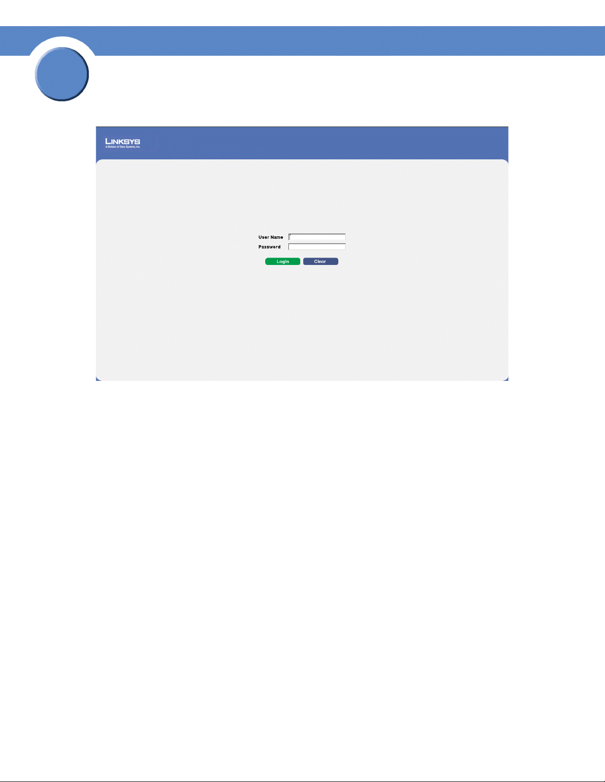
2. Enter the device’s IP address in the address bar and press Enter. An Appendix 1, "Enter Network
Password Page" opens:
Chapter 1:
1
Page 10
1
Chapter
SFE2000/SFE2000P Gigabit Ethernet Switch Reference Guide
Enter Network Password Page
3. Enter a user name and password. The default user name is “admin.”
with a default password, and can be configured without entering a password. Passwords are both
case sensitive and alpha-numeric.
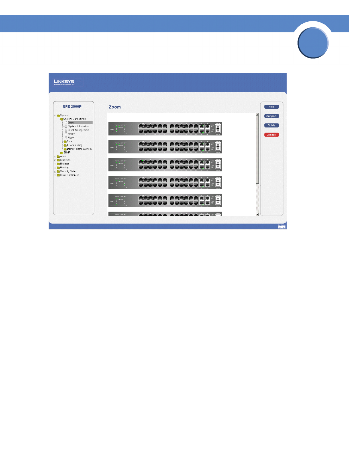
4. Click Login The Embedded Web System Home Page opens:
Note If you have logged in automatically via the Service Router user interface, the Tree and Device
views appear and allow you to navigate through the various areas of the web interface. However,
the following page will appear within the frame provided by the Service Router user interface.
The device is not configured
2
Chapter 1:
Page 11
SFE2000/SFE2000P Gigabit Ethernet Switch Reference Guide
Embedded Web System Home Page
Chapter
1
Chapter 1:
3
Page 12
1
Chapter
SFE2000/SFE2000P Gigabit Ethernet Switch Reference Guide
Understanding the Interface
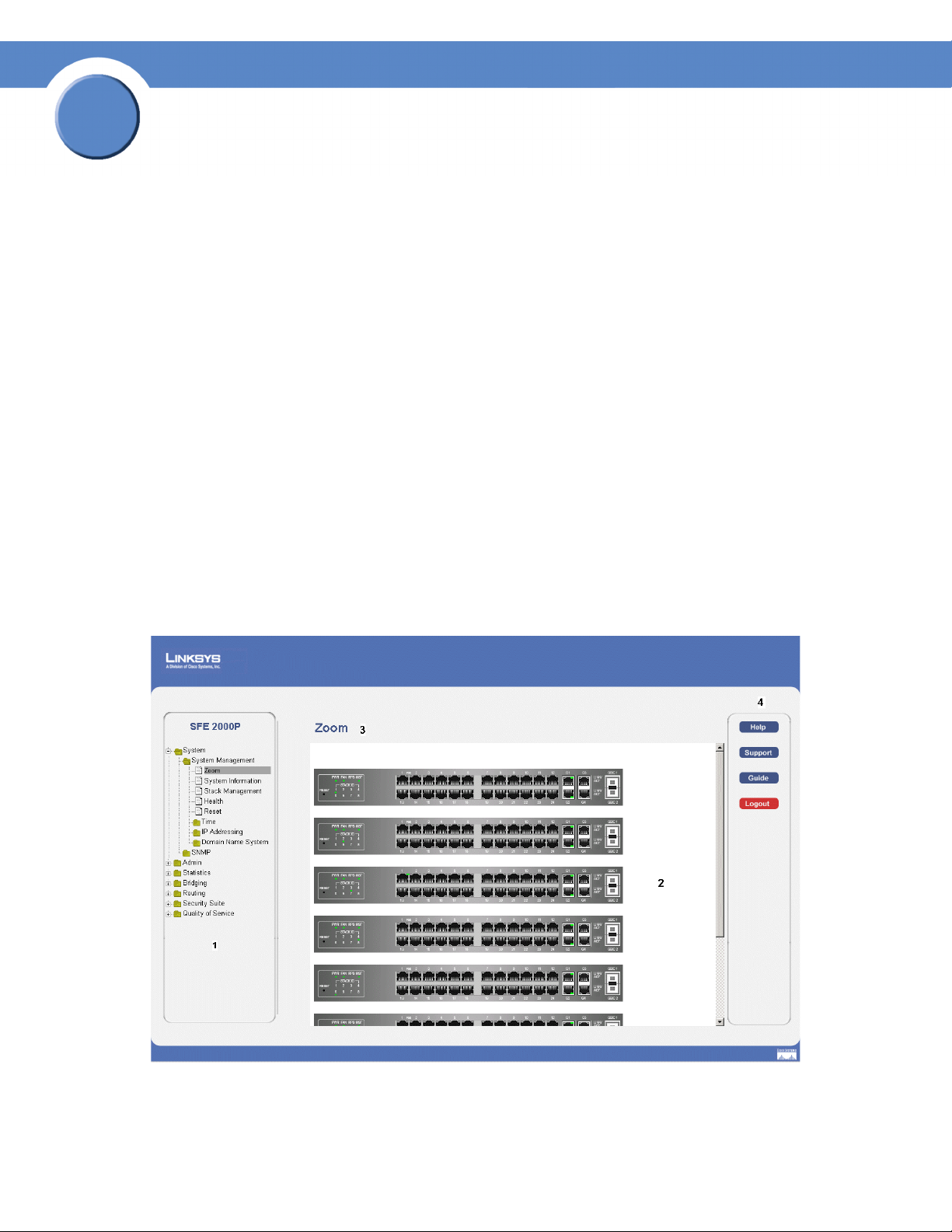
The following table lists the interface components with their corresponding numbers:
Interface Components
Component Description
1
Tree View The Tree View provides easy navigation through the configurable device
features.The main branches expand to provide the subfeatures.
2 Device View The device view provides information about device ports, current
configuration and status, table information, and feature components.The
device view also displays other device information and dialog boxes for
configuring parameters.
3 Table Area The Table area enables navigating through the different device features.
Click the tabs to view all the components under a specific feature.
4 EWS Information The EWS information tabs provide access to the online help, contains
information about the EWS.
Linksys User Interface Components
4
Chapter 1:
Page 13
Chapter
SFE2000/SFE2000P Gigabit Ethernet Switch Reference Guide
This section provides the following additional information:
•
Device Representation — Provides an explanation of the Linksys user interface buttons, including both
management buttons and task icons.
•
Using the Linksys Management Buttons — Provides instructions for adding, modifying, and deleting device
parameters.
Device Representation
The Linksys home page displays a graphical representation of the device:
Device Representation
1
The Linksys home page contains a graphical SFE2000 and SFE2000P front panel illustration.
Chapter 1:
5
Page 14
1
Chapter
SFE2000/SFE2000P Gigabit Ethernet Switch Reference Guide
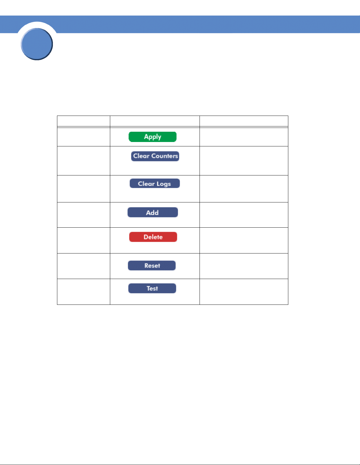
Using the Linksys Management Buttons
Device Management buttons and icons provide an easy method of configuring device information, and
include the following:
Device Management Buttons
Button Name Button Description
Apply Applies changes to the device.
Clear All Counters Clears statistic counters
Clear Logs Clears log files
Add Opens an Add page
Delete Removes entries from tables
Reset the settings of
Selected Port to
Default
Test Now Performs cable tests.
Resets the settlings of a selected port
to the default settings
6
Chapter 1:
Page 15
Chapter
SFE2000/SFE2000P Gigabit Ethernet Switch Reference Guide
Using Screen and Table Options
Linksys contains screens and tables for configuring devices. This section contains the following topics:
• Appendix 1, "Adding Device Information"
• Appendix 1, "Modifying Device Information"
• Appendix 1, "Deleting Device Information"
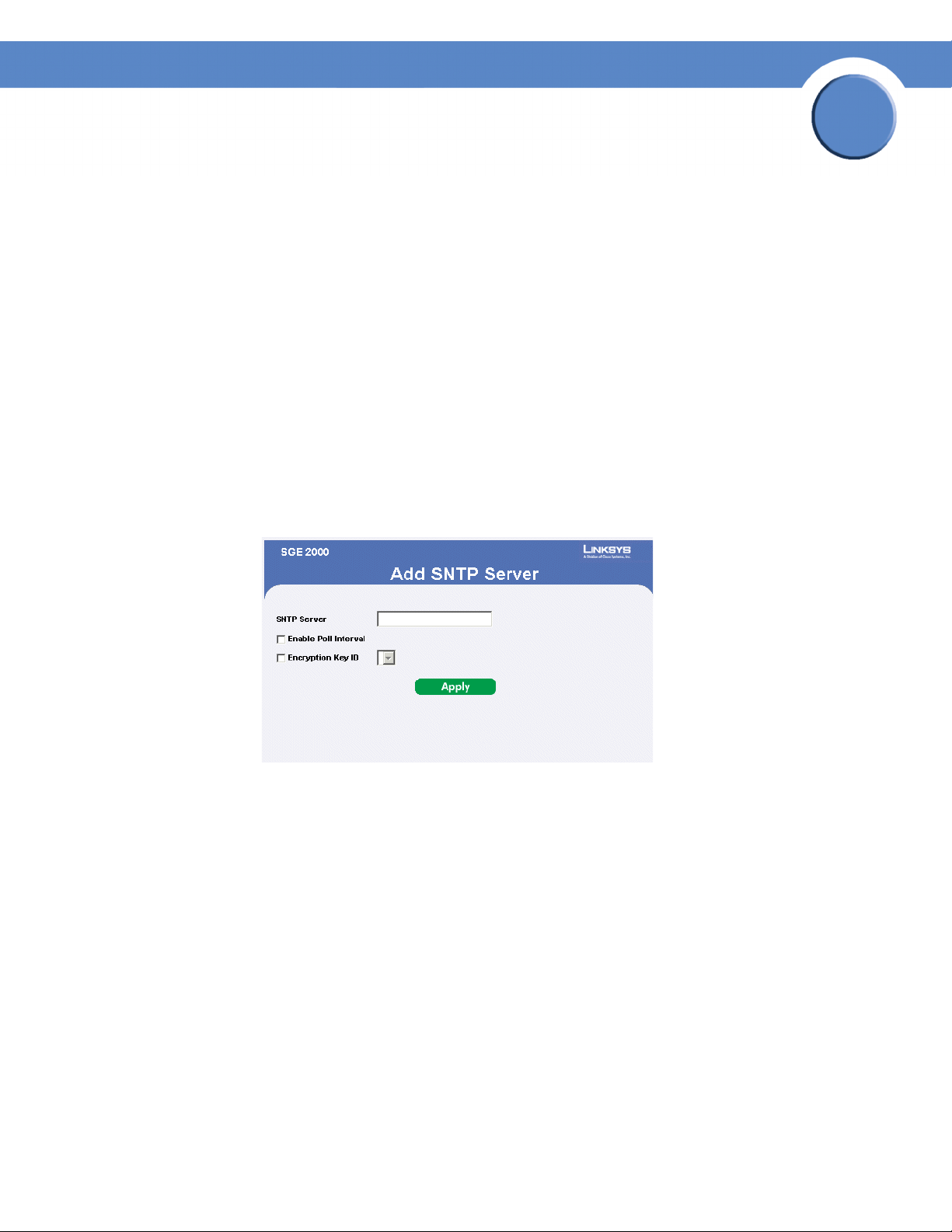
Adding Device Information
User defined information can be added to specific EWS pages, by opening a new Add page. To add
information to tables or EWS pages:
1. Open an EWS page.
2. Click the Add button. An add page opens, for example, the Add SNTP Server Page:
Add SNTP Server
1
3. Define the fields.
4. Click Apply. The configuration information is saved, and the device is updated.
Modifying Device Information
1. Open the EWS page.
2. Select a table entry.
3. Click the Edit Button. A Modify page opens, for example, the Interface priority Page opens:
Chapter 1:
7
Page 16

1
Chapter
SFE2000/SFE2000P Gigabit Ethernet Switch Reference Guide
Edit Interface Priority
4. Define the fields.
5. Click Apply. The fields are modified, and the information is saved to the device.
Deleting Device Information
1. Open the EWS page.
2. Select a table row.
3. Check the Remove checkbox.
4. Click the Delete button. The information is deleted, and the device is updated.
8
Chapter 1:
Page 17
Chapter
SFE2000/SFE2000P Gigabit Ethernet Switch Reference Guide
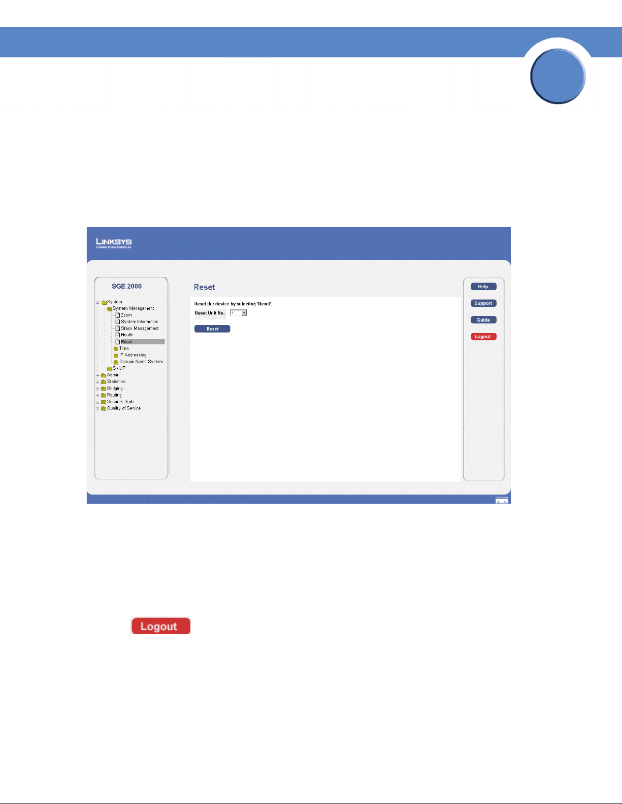
Resetting the Device
The Reset page enables the device to be reset from a remote location. Save all changes to the Running
Configuration file before resetting the device. This prevents the current device configuration from being
lost. To reset the device:
1. Click System > General > Reset. The Reset page opens.
Reset Page
1
2. Click the Reset button.
resetting the entire stack. If the master unit is reset, the device is reset, and a prompt for a user name
and password is displayed.
3. Enter a user name and password to reconnect to the Web Interface, if the stack is not part of a full
Linksys One system. If the stack is part of a Linksys One system, login is automatically done from
the Service Router.
Each unit can be reset individually. Resetting the stack master results in
Logging Off The Device
1. Click . The system logs off. The Embedded Web System Home Page closes.
Chapter 1:
9
Page 18

1
Chapter
SFE2000/SFE2000P Gigabit Ethernet Switch Reference Guide
10
Chapter 1:
Page 19
Chapter
SFE2000/SFE2000P Gigabit Ethernet Switch Reference Guide
Managing Device Information
This section provides information for defining both basic and advanced system information. This section
contains the following topics:
• Understanding the Device Zoom View
• Defining General System Information
• Managing Stacks
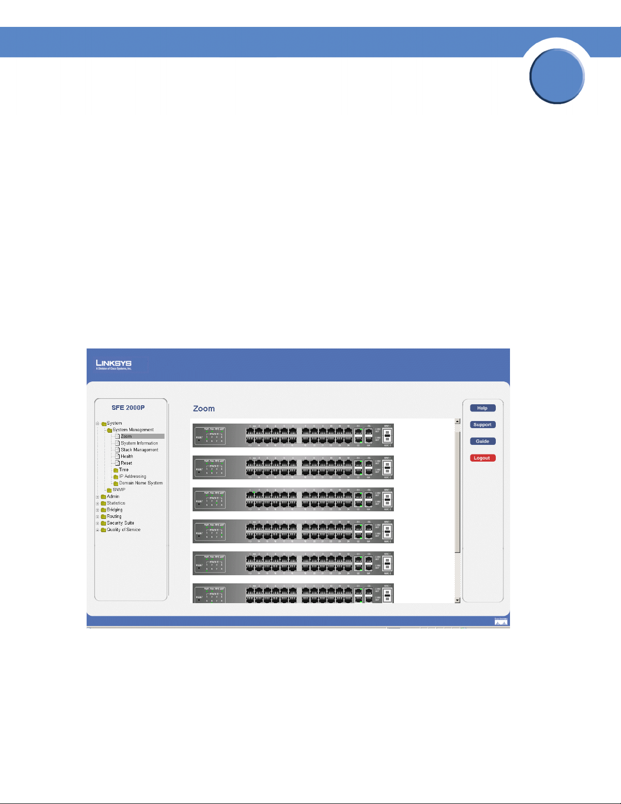
Understanding the Device Zoom View
The Zoom Page is the main window used for viewing the devices either in stand-alone mode or operating
in a stack. To open the Zoom Page:
1. Click the System > System Management > Zoom. The Zoom Page opens:
Zoom Page
2
The Zoom Page contains the following port indicators:
•
Green — Indicates the port is currently operating.
• Red — indicates the port is not currently operating.
Chapter 2:
11
Page 20
2
Chapter
SFE2000/SFE2000P Gigabit Ethernet Switch Reference Guide
Defining General System Information
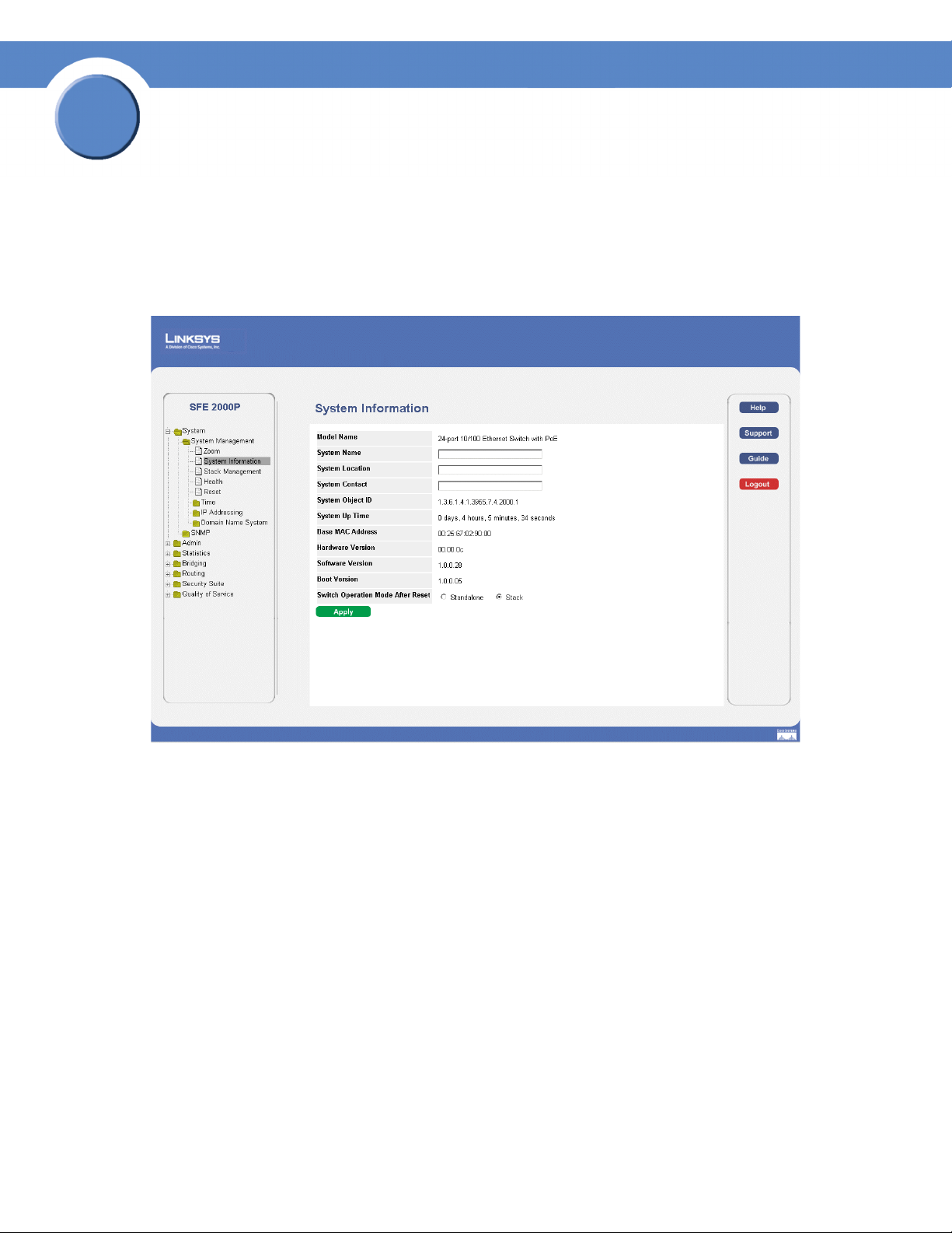
SFE 2000P System Information
The System Information page contains parameters for configuring general device information.
SFE 2000P System Information Page
The System Information page contains the following fields:
• Model Name — Displays the user defined user name.
• System Name — Displays the user configured name of the system. Configured in the Network page.
• System Location — Defines the location where the system is currently running. The field range is
up-to 0-160 Characters.
• System Contact — Defines the name of the contact person.The field range is up to 0-160
Characters.
• System Object ID— Displays the vendor’s authoritative identification of the network management
subsystem contained in the entity.
• System Up Time — Displays the amount of time that has elapsed since the last device reset. The
system time is displayed in the following format: Days, Hours, Minutes and Seconds. For example:
41 days, 2 hours, 22 minutes and 15 seconds.
12
Chapter 2:
Page 21

Chapter
SFE2000/SFE2000P Gigabit Ethernet Switch Reference Guide
• Base MAC Address — Displays the device MAC address. If the system is in stack mode, the Base
MAC Address of the master unit is displayed.
• Hardware Version — Displays the hardware version number. If the system is in stack mode, the
hardware version of the master unit is displayed.
• Software Version — Displays the software version number. If the system is in stack mode, the
version of the master unit is displayed.
• Boot Version — Indicates the system boot version currently running on the device. If the system is
in stack mode, the version of the master unit is displayed.
• Switch Operation Mode After Reset — Indicates the mode the device operates in after the system
is reset. A switch may operate in one of two modes: stack or standalone. Either mode is selected by
the user during software boot or in the web interface’s System Information page. The new mode
takes effect after the unit is reset. The factory default is stack mode. The possible field values are:
– Standalone — Indicates the device operates as a Standalone device after the system is reset.
A switch operating in standalone mode runs as an independent, single unit. All ports of a
standalone switch operate as normal Ethernet links. A standalone switch does not participate
in a stack even if physically connected to a stack.
2
– Stack — Indicates the device operates as a Stacked unit after the system is reset. A switch
operating in stack mode is not an independent unit, but a member of an organized group of
switches known as a stack. A stack consists of one Stack Master control switch, one Master
Backup switch and up to six Stack Member switches. In some cases, a unit in stack mode
that is not connected to any other units may operate as a “stack–of-one.”
2. Define the relevant fields.
3. Click Apply. The system information is defined, and the device is updated.
Managing Stacks
Stacking allows you to build a switch with many more ports than would be available in a single unit. The
stack is managed by one of the units (called the Stack Master) and all of the other units serve as ports
only.
You can build stacks by building a new stack from a group of switches, or adding new units to an
existing stack. Stacks can be automatically or manually configured.
NOTE: Two ports of each unit in a stack mode (ports 12
and 24 on GE units, and ports G1 and G2 on FE units) are
reserved for stacking links, and cannot be used for regular
network connections.
Chapter 2:
13
Page 22
2
Chapter
SFE2000/SFE2000P Gigabit Ethernet Switch Reference Guide
Building Automatically-Configured Stacks
Building a New Stack
The easiest way to build a stack is to use a group of switches, each of which is in factory default mode:
NOTE: If the units to be used in building the new stack
have been used previously, we recommend that you reset
them to the factory default by holding the reset button for at
least 10 seconds before using them.
1. Connect the units physically through the stacking ports, using standard Ethernet cables.
2. Power the units on. After a short interval the stack becomes operational, with one of the units
selected as the Stack Master. The unit selected as Stack Master is indicated by a lit green “MST”
LED on its front panel. If a serial console connection is desired, the serial cable should be connected
to the console port of the unit serving as the Stack Master.
Adding Units to a Running Stack
1. Reset the units that will be added by restoring them to the factory default mode. Connect the units
physically to the stack.
2. Power the units on. After a short interval, they will become members of the stack.
Building Manually-Configured Stacks
You can manually configure stacks, including choosing a specific unit as the Stack Master. You must
assign a unique Unit ID (from 1 to 8) to each stack member.
Building a New Stack
1. Reset all relevant units to by restoring them to the factory default mode.
2. Connect the units physically through the stacking ports, using standard Ethernet cables.
3. Assign each unit its desired number, making sure no duplicates exist, and reset the stack.
Adding Units to a Running Stack
1. Reset the units to be added by restoring them to the factory default mode.
2. Connect the units physically to the stack.
14
Chapter 2:
Page 23
Chapter
SFE2000/SFE2000P Gigabit Ethernet Switch Reference Guide
3. Power the units on. After a short interval, they will become stack members, but will have
automatically-assigned Unit IDs. Assign each such unit its desired Unit ID (using the Stack
Management Interface through the console port, by Telnet, or by using the graphical user interface
(GUI).
4. Reset the units to make this assignment permanent.
NOTE: We recommended that if you manually assign a
Unit ID to one unit, you manually assign Unit IDs to all
units. Using a mix of both system-assigned and manuallyassigned IDs in your network can impact system
performance.
The unit that is assigned the Unit ID 1 is the Stack Master, and its front panel “MST” LED lights green.
The unit assigned the Unit ID 2 is the Backup Master.
Understanding Stack Resiliency
2
Stacks can be configured in ring or chain topologies. We recommend configuring the stack in ring
topology, due to the high resiliency in case of unit failure or stacking links failure.
Additionally, if a redundant power supply is present, we recommend connecting the Stack Master and
Backup Master units to the redundant power supply.
Understanding Advanced Stacking
To understand advanced stacking, you must understand Unit IDs and how they are allocated, and the
stack unit startup process.
Unit IDs
Each unit in a stack has an assigned unique Unit ID number. The following sections describe the Unit
IDs and their characteristics.
Stack Master
The unit assigned the Unit ID number 1 serves as the Stack Master. All other units are stack members.
The Stack Master provides a single point of control, configuration and management for the entire stack,
and stores the configuration for all stack members. (Members do not store any configuration
information.)
Stack Backup Master
The unit assigned the Unit ID number 2 is a special stack member that serves as the stack Backup
Master. A stack Backup Master assumes the role of Stack Master for the remaining stack members if the
stack Master fails or is disconnected.
Chapter 2:
15
Page 24
2
Chapter
SFE2000/SFE2000P Gigabit Ethernet Switch Reference Guide
The Stack Master stores a copy of the active configuration on the Backup Master. This copy is used only
if the Backup Master assumes the role of Stack Master.
NOTE: Only the configuration file is copied. Any
dynamically-filled tables (for example, learned addresses)
are not copied from the Stack Master to the Backup Master.
If the Backup Master assumes the role of Stack Master, it
builds its own dynamic tables.
Stack Members
The units assigned the Unit IDs 3 through 8 are called stack members. A stack member operates only as
a member of the stack under the direction of an operational Stack Master (or a Backup Master that has
assumed the Stack Master role). Stack members are not directly manageable and configurable, and must
be managed through the Stack Master. They do not contain any meaningful configuration information,
including their own configuration. If an operational Stack Master is not present and reachable, these
units are not functional.
Master-Enabled Units
Units that are assigned a Unit ID number of 1 or 2 are called master-enabled units. Only master-enabled
units participate in the Master Election process (see below) when they are initialized, are inserted into a
new stack, or lose connectivity with the existing Stack Master. Only master-enabled units participate in
the Master Election process and can become the Stack Master or Backup Master. (Units that are assigned
a Unit ID of 3 through 8 can only become a Stack Master or a Backup Master if they are manually
configured by the system administrator or if they are reset to the factory default mode.)
Unit ID Allocation
Units are shipped from the factory without an assigned Unit ID, and must be assigned a unique Unit ID
before they can operate as part of a stack. Unit ID numbers are assigned to units in one of two ways:
• Unit ID numbers are assigned by the system administrator, and can be changed only manually by
the system administrator.
• Unit ID numbers are allocated to a stack member unit by the Stack Master during system
initialization.
A unit that was assigned a Unit ID will usually keep this number even after it is rebooted. The Stack
Master may reallocate Unit IDs during system initialization to resolve duplicate Unit ID conflicts (see
below). Manually assigned Unit IDs cannot be changed by the Stack Master, even if there is a conflict.
Unit ID assignment or change takes effect only during system initialization and does not take place
during system runtime. Units of a stack do not have to be numbered in sequence, and can be
interconnected as long as each unit has a unique ID and at least one unit of the stack serves as Stack
Master.
16
Chapter 2:
Page 25

Chapter
SFE2000/SFE2000P Gigabit Ethernet Switch Reference Guide
Stack Unit Startup Process
When a unit in stack mode is initialized (powered up or rebooted), it goes through the following steps:
1. The Master Discovery and Master Election processes.
2. Unit ID allocation by the Stack Master (including duplicate Unit ID conflict resolution).
3. Unit and port configuration by the Stack Master.
Master Discovery Process
When a unit in stack mode initializes, its behavior depends on its Unit ID (if one is configured):
• If the unit does not have a current Unit ID (that is, the unit is in factory default mode) and if there
is a Stack Master, the unit is allocated a Unit ID number from the Stack Master. If there is no
Stack Master, then the unit participates in the Master Election process, and may be chosen as the
new Stack Master or Backup Master.
• If the unit’s current Unit ID is 1 or 2 (that was previously allocated, even if used in a different
stack), then the unit participates in the Master Election process.
2
• If the unit has a current Unit ID (that was previously allocated, even if used in a different stack),
the unit tries to act according to its Unit ID number in the new stack. For example, if the unit’s
current Unit ID is 3 through 8, it will try to connect to the running Stack Master, and will not
proceed to the next stage until contact with the Stack Master is made. These units will not
participate in the Master Election process, and if no Stack Master is present, the units are
effectively shut down.
The Stack Master and all other stack units carry out a continuous process of Master Discovery by
frequently exchanging stack control messages. This allows units to know if another unit fails or becomes
unreachable.
Master Election Process
When units in stacking mode initialize, one of the units is elected as the Stack Master. If a unit in the
stack was set to “Force Master” by the system administrator, that unit is elected as the Stack Master.
Only master-enabled stack units (for example, those with the Unit ID of 1 or 2) can be configured as
“Force Master.”
If the stack contains units whose unique Unit ID is 1 or 2, then one of these two units will be the Stack
Master. It does not matter if the Unit ID was originally assigned automatically or manually. These units
are called master-enabled units. If there is only one master-enabled unit, it will be elected as the Stack
Master (even if its Unit ID is 2).
If there are two master-enabled units, the two units decide which of them is the Master by checking
which one has been running for a longer time (in intervals of 10 minutes). The unit that has been running
for the longer time will be the Stack Master. If they have been running for the same amount of time, the
unit with the Unit ID of 1 will be the Stack Master. If both units have been running for the same amount
of time and both units have the same Unit ID, the unit with a lower MAC (hardware) address will be
selected as the Stack Master.
Chapter 2:
17
Page 26

2
Chapter
SFE2000/SFE2000P Gigabit Ethernet Switch Reference Guide
If the stack contains one or more units without a current Unit ID (the units are in factory default mode),
then one of these units will be the Stack Master. The unit selected to be the Stack Master is the one
running for the longest time (in intervals of 10 minutes), or, if all units are running for the same amount
of time, the one with the lowest MAC (hardware) address.
The Master Election process ensures that the stack has a Stack Master. The Stack Master has the Unit ID
of 1 and the Backup Master, if it exists, has the Unit ID of 2. Alternatively, the Stack Master has the Unit
ID of 2 and the Backup Master, if it exists, has the unit ID of 1.
If a master-enabled unit is added to a stack and powered on, when it comes up it invokes the Master
Election process, even though the rest of the stack already has an elected master. Because the unit is new,
it loses the election and joins as a stack member or Backup Master.
Unit ID Allocation and Duplicate Unit ID Conflict Resolution
After a Stack Master is elected, it allocates Unit IDs to units that do not have a currently assigned Unit ID
(units that are in factory default mode). The Stack Master also attempts to resolve all cases of units with
duplicate Unit IDs. The Stack Master changes the Unit IDs of units that have a duplicate current Unit ID,
provided that there are available, unused Unit IDs. In a merged stack, if the Stack Master unit remains as
the Stack Master, units that were in its group will keep their unit IDs. Members of other groups are
renumbered.
If the conflict occurs after the units reboot, the conflict is resolved as follows:
• If both duplicate units are in auto (self ordering) mode, then the unit ID with the lower MAC
(hardware) address will keep its unit ID. The other unit is assigned a new unit ID.
• If one of the duplicates is in auto (self ordering) mode, and the other unit is in manual mode,
then the manual mode unit will keep its ID and the other is assigned a new unit ID.
• If both duplicate units are in manual mode, then both of them are shut down.
If the Stack Master is able to allocate a unique Unit ID to each unit, then all units can operate as a stack.
If the Stack Master is unable to allocate a Unit ID to a unit, that unit is effectively shut down and will not
participate in the stack. For example, units with a conflicting manually-set Unit ID number are shut
down because the Stack Master cannot override the system administrator’s assignment and resolve the
conflict.
If there are more units than the maximum number allowed in a stack, and the incoming units are already
in factory default mode (they do not have unit ID assigned), then a Stack Master is elected following the
Master Discovery and Master Election processes. All other units remain shut down.
18
Chapter 2:
Page 27
Chapter
SFE2000/SFE2000P Gigabit Ethernet Switch Reference Guide
Occasionally, due to a race condition during the boot process, some of the units might be connected and
join the stack. If the incoming units already have a unit ID, then none of them will join the stack and all
are left in shutdown mode because there is no way for the Stack Master to determine their Unit ID
preference.
NOTE: If a unit is shut down, its stacking links are inactive.
If the stacking units are connected in a chain topology, the
shutdown of one unit breaks the chain and can cause other
units to be shut down if they have no active link to the Stack
Master unit.
Configuring Units and Ports
After the Master Discovery and Master Election processes, each unit in the stack has a unique Unit ID,
one of the units is the Stack Master, and one of the units may serve as the Backup Master. The Stack
Master then configures each of the member units and its ports according to the configuration file present
on the Stack Master. If the stack has a Backup Master, the configuration file is copied to the Backup
Master.
2
After all the units and ports are configured, the stack enters normal operational mode. If a change is
made to the system configuration, the change is stored by the Stack Master and is copied to the Backup
Master if one exists.
You can use the command-line interface (CLI) or GUI to configure the stack units.
Setting the Unit’s Operational Mode
Use the GUI to set the unit’s operational mode to standalone or stack. This configuration takes effect
after the next reboot.
Configuring the Stack Master and Unit ID
The Stack Management Page allows network managers to either reset the entire stack or a specific
device. Device configuration changes that are not saved before the device is reset are not saved. If the
Stack Master is reset, the entire stack is reset.
To open the Stack Management Page:
1.
Click System > System Management > Stack Management. The Stack Management Page opens:
Chapter 2:
19
Page 28
2
Chapter
SFE2000/SFE2000P Gigabit Ethernet Switch Reference Guide
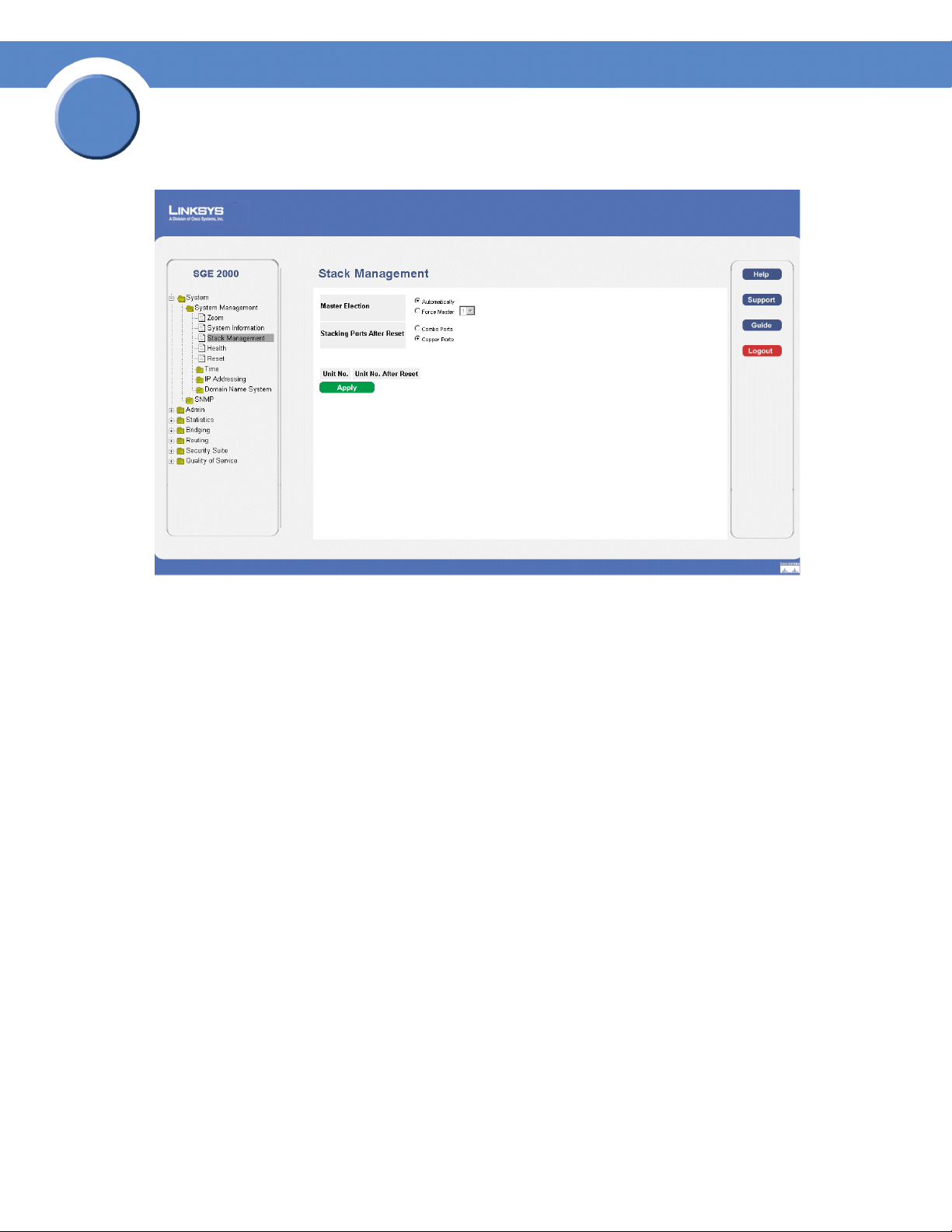
Stack Management Page
The Stack Management Page contains the following fields:
• Master Election — Indicates the method of electing the Stack Master device. The possible values
are:
– Automatically — The master is selected automatically by software.
– Force Master — The unit is forced to be master of the stack. Note that only units with the
Unit ID of 1 or 2 can be the stack master.
• Stacking Ports After Reset — Allows the user to decide what cable type is in use. The possible
values are:
– Combo Ports — Indicates that the combo port is used as the stacking port.
– Copper Ports — Indicates that the copper port is used as the stacking port.
• Unit No.— Displays the current Stacking Master.
• Unit No. After Reset — Indicates the stacking member elected Stacking Master after the device is
reset.
2. Define the relevant fields.
3. Click Apply. Stack management is defined, and the device is updated.
20
Chapter 2:
Page 29
Chapter
SFE2000/SFE2000P Gigabit Ethernet Switch Reference Guide
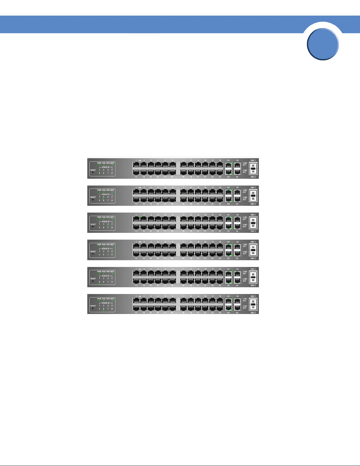
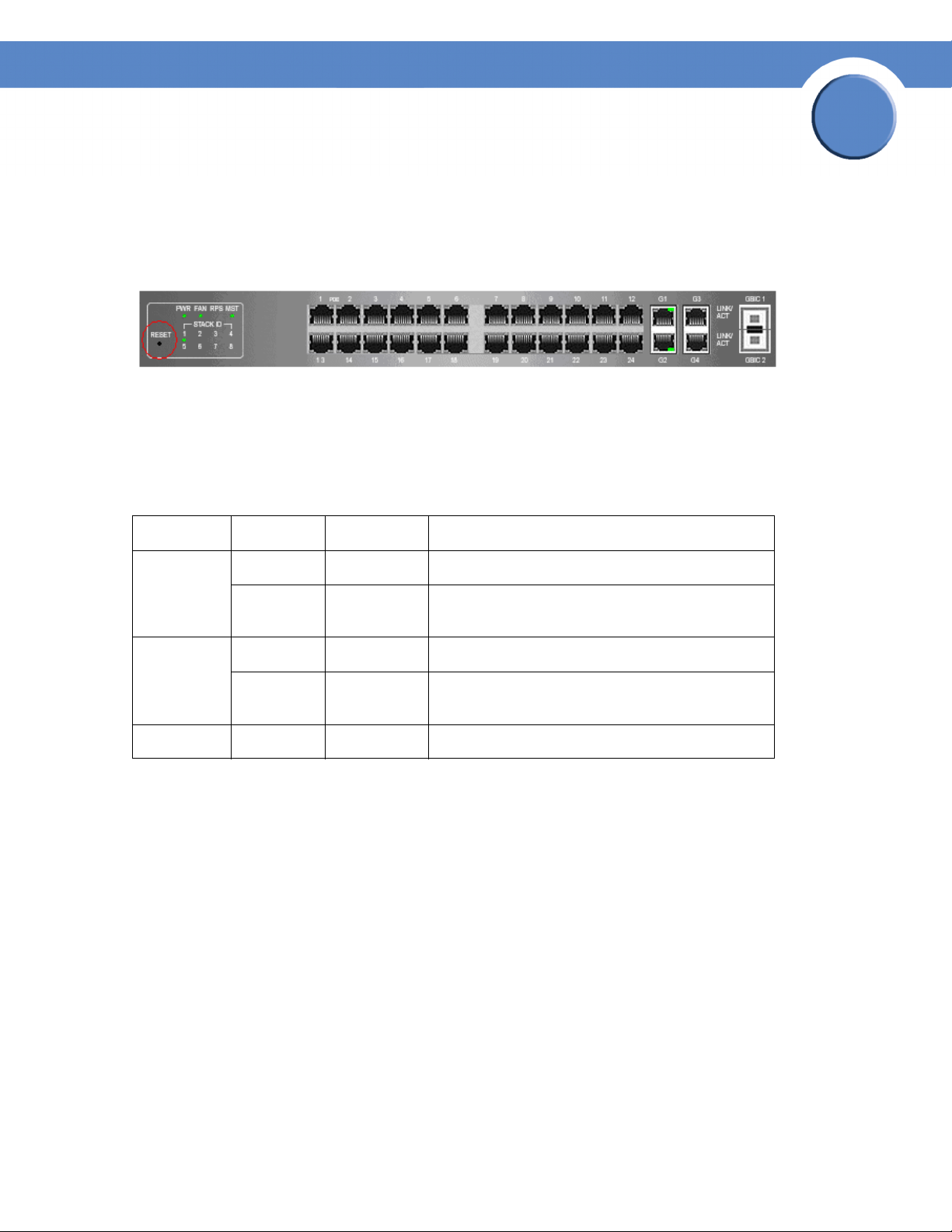
Resetting the Unit to Factory Default Mode
To reset the unit to the factory default settings, press the front panel RESET button (see Figure 3.) The
unit is set to Stack mode with a Unit ID of 0.
Understanding LED Indicators
Each unit contains a Master LED indicator and eight unit LEDs. The LED status definitions are shown in
the table below.
2
LED Mode Color Description
Master Solid Green The switch is the Stack Master.
Off N/A The switch is not the Stack Master or the switch is
not stacked.
ID n Solid Green The switch is Unit ID n.
Off N/A The switch is not Unit ID n or the switch is not
stacked.
All ports Solid Red The switch is powered on, but not operational.
Stack Troubleshooting and Maintenance
Replacing a Failed Member Stack Unit in an Operational Stack
If a unit that is not the Stack Master fails in an operational stack, the Stack Master discovers that the unit
is no longer responding during the Master Discovery process. The Stack Master directs all other stack
members to route unit-to-unit traffic around the failed unit using the ring topology of the stacking
connections. Concurrently, the Stack Master notifies the system administrator of the failure by sending
SYSLOG messages and SNMP traps.
Because all traffic has been routed around the failed unit, when it is disconnected from the stack, the
stack continues to run as long as all other stacking connections are left intact.
Chapter 2:
21
Page 30

2
Chapter
SFE2000/SFE2000P Gigabit Ethernet Switch Reference Guide
When a new unit is inserted in the stack and powered on, the following occurs:
1. The incoming unit, which is in stack mode, performs the Master Discovery process, and may
participate in the Master Election process.
• If the incoming unit has a Unit ID of 1 or 2 (it is a master-enabled unit) it initiates the Master
Election process. However, because the running Stack Master has a longer runtime, the current
Stack Master retains its position and the incoming unit does not become the new Stack Master.
• If the incoming unit has a Unit ID of 3 through 8, it attempts to become a member unit of the
stack, subject to control by the already running Stack Master, and the Master Election process
does not occur.
2. The Stack Master performs Unit ID allocation and the conflict resolution process.
• If the incoming unit did not have an assigned Unit ID (that is, it is in factory default mode), it is
assigned the lowest available Unit ID by the Stack Master. We recommend that you use the
automatically-assigned unit ID mode because it provides better resiliency to the stack.
• If the incoming unit already has an assigned Unit ID, and that Unit ID is unused in the current
stack, the incoming unit keeps its assigned Unit ID and the Stack Master applies any
configuration relevant to that Unit ID to the incoming unit.
• If the incoming unit already has an assigned Unit ID, and that Unit ID conflicts with a unit ID in
the current stack, the Stack Master allocates a new Unit ID to the incoming unit, giving it the
lowest available Unit ID. However, if the incoming unit has a manually assigned Unit ID, the
Stack Master cannot change it. If the incoming unit cannot be assigned an available Unit ID,
then it is shut down and is not joined to the stack.
3. The Stack Master performs unit and port configuration for the incoming unit.
• Any configuration information that is relevant to the number assigned to the incoming unit is
applied by the Stack Master. For example, if the incoming unit is assigned the same Unit ID of
the unit it replaced, then when possible, it receives the same configuration as the failed unit.
• If the incoming unit is identical to the replaced unit, the entire configuration of the replaced unit
is applied to the incoming unit and the stack returns to the state it was in before unit failure.
If the incoming unit is not identical to the unit that failed, the Stack Master applies the configuration in
the following manner:
• If a 24-port unit replaces a failed 48-port unit, the ports of the incoming unit are configured
according to the configuration of the first 24 ports of the failed unit.
NOTE: The configuration of all 48 ports of the failed unit is
kept in memory, even though the first 24 are currently
applied. If, in the future, a 48 port unit is inserted and
assigned the same Unit ID, it is configured the same as the
original failed 48-port unit.
22
Chapter 2:
Page 31

Chapter
SFE2000/SFE2000P Gigabit Ethernet Switch Reference Guide
• If a 48-port unit replaces a 24-port unit, then the first 24 ports of the incoming unit are
configured according to configuration of the ports of the failed unit. The remaining ports of the
incoming are configured according to the default settings.
• If the units have uplink ports, then the first uplink port of the incoming unit is configured
according to the configuration of the first uplink port of the failed unit.
Replacing a Failed Stack Master Unit in an Operational Stack
When the Stack Master unit fails, the stack Backup Master, using the Master Discovery process,
discovers that the Stack Master unit no longer responds. The Backup Master takes over as the Stack
Master. The Backup Master (now the Stack Master) directs all other stack members to route unit-to-unit
traffic around the failed unit using the ring topology of the stacking connections. Concurrently, the
Backup Master notifies the system administrator of the failure by sending SYSLOG messages and
SNMP traps.
Because all traffic has been routed around the failed unit, when it is disconnected from the stack, the
stack continues to run as long as all other stacking connections are left intact.
2
When a new unit is inserted in the stack and powered on, the following occurs:
1. The incoming unit, which is in stack mode, performs the Master Discovery process, and may
participate in the Master Election process.
• If the incoming unit has a Unit ID of 1 or 2 (it is a master-enabled unit) it initiates the Master
Election process. However, because the running stack Backup Master has a longer runtime (if it
has been running for more than 10 minutes) it remains the Stack Master and the incoming unit
does not become the new Stack Master. This can cause an incoming unit with a Unit ID of 1 to
serve as the stack Backup Master, while the current unit with the Unit ID of 2 remains the active
Stack Master.
2. The Stack Master performs Unit ID allocation and the conflict resolution process.
• If the incoming unit did not have an assigned Unit ID (that is, it is in factory default mode), it is
assigned the lowest available Unit ID by the Stack Master. We recommend that you use the
automatically-assigned unit ID mode because it provides better resiliency to the stack.
• If the incoming unit already has an assigned Unit ID, and that Unit ID is unused in the current
stack, the incoming unit keeps its assigned Unit ID and the Stack Master applies any
configuration relevant to that Unit ID to the incoming unit.
• If the incoming unit already has an assigned Unit ID, and that Unit ID conflicts with a unit ID in
the current stack, the Stack Master allocates a new Unit ID to the incoming unit, giving it the
lowest available Unit ID. However, if the incoming unit has a manually assigned Unit ID, the
Stack Master cannot change it. If the incoming unit cannot be assigned an available Unit ID,
then it is shut down and is not joined to the stack.
Chapter 2:
23
Page 32

2
Chapter
SFE2000/SFE2000P Gigabit Ethernet Switch Reference Guide
3. The Stack Master performs unit and port configuration for the incoming unit.
• Any configuration information that is relevant to the number assigned to the incoming unit is
applied by the Stack Master. For example, if the incoming unit is assigned the same Unit ID of
the unit it replaced, then when possible, it receives the same configuration as the failed unit.
• If the incoming unit is identical to the replaced unit, the entire configuration of the replaced unit
is applied to the incoming unit and the stack returns to the state it was in before unit failure.
Splitting a Stack
A working stack can be split into two groups, either by failure of a stacking link connecting two units in
the stack, or by a failed unit in a chain topology that causes disconnection between two units in the stack.
In this case, each group is considered as an independent running stack configuration. For each group,
there are three scenarios.
The Stack Master and Backup Master Units Remain in a Group
In this scenario, the Stack Master routes around the missing units. The Master Discovery, Master
Election and Unit ID Allocation & Duplicate Unit ID Conflict Resolution processes occur with the
following results:
• Any configuration information contained in the Stack Master that is relevant to the units which
remained in the split group remains unchanged.
• Topology information (the information for each unit on how to send traffic to any other unit in the
stack) managed by the Stack Master includes only units that are reachable (connected) following the
split.
• The split stack continues to work as it previously did, but with fewer units.
• No unit ID changes are performed in each of the split stacks.
• The Stack Master notifies the system administrator of the removed units and ports that belong to
the unreachable units by sending SYSLOG messages and SNMP traps. They are reported as “not
present.”
The Stack Master or the Backup Master Unit Remains in a Group
If the Stack Master unit remains in the group, the scenario described in “Replacing a Failed Member
Stack Unit in an Operational Stack” applies. If the Backup Master unit remains in the group, the scenario
described in “Replacing a Failed Stack Master Unit in an Operational Stack” applies.
NOTE: If the stack is split in two groups, one with the
Stack Master and one with the Backup Master, both groups
will function.
24
Chapter 2:
Page 33

Chapter
SFE2000/SFE2000P Gigabit Ethernet Switch Reference Guide
The Master Discovery, Master Election and Unit ID Allocation & Duplicate Unit ID Conflict Resolution
processes occur with the following results:
• If the Stack Master unit remains in the split stack, the Stack Master discovers (using the Master
Discovery process) that the Master Backup unit no longer responds. The Stack Master notifies
the system administrator (using SYSLOG messages and SNMP traps) of the removed units and
ports that belong to the unreachable units and they are reported as “not present.”
• If the Backup Master unit remains in the split stack, the Backup Master determines this as a case
of Stack Master failure and takes over and manages the remaining units as a stack while keeping
its previous Unit ID number. Because the Backup Master was not acting as a master prior to the
split, it initiates a topology database and ports learning process. Traffic might be halted for a
short period of time until synchronization (unit and port configuration) is completed. New units
discovered by the Backup Master notify the system administrator (using SYSLOG messages and
SNMP traps).
• The partial stacks both continue to work as they did previously, but with fewer units.
• No unit ID changes are performed in each of the partial stacks.
2
• If each part of the stack has a Stack Master (for example, one contains the original Stack Master,
and one contains the Backup Master), and are operating as two separate stacks, both Stack
Masters contain the same configuration and use the same IP address.
CAUTION: If both Stack Masters use the same IP Address,
problems can occur on the network, because users cannot
connect to one of the stacks through its IP address.
Neither the Stack Master Unit or the Backup Master Unit Remains in the Group
This scenario is the same as that of a failed Stack Master where no Backup Master is available. The
following concepts apply:
• Units whose ID numbers are 3 through 8 in this part of the original stack will not renumber
themselves, and will remain shut down until a master-enabled unit is connected and begins to
operate as the Stack Master. The Master Discovery process discovers that the Stack Master has
failed.
• In this group, the units lose connection with the Stack Master. Since they began as a running
stack and none of them are in factory default mode, renumbering does not occur, and even a
reset of the units will not affect unit ID assignment, because units can be renumbered only by a
Stack Master.
• No unit ID changes are performed in each one of the two groups.
Chapter 2:
NOTE: None of the units in either group will renumber
themselves.
25
Page 34

2
Chapter
SFE2000/SFE2000P Gigabit Ethernet Switch Reference Guide
Merging Two Stacks
To merge two working stacks and create one stack, first decide if you will merge the stacks while the
incoming units are powered off during insertion, or if both stacks will be running when merged.
If the incoming units are powered off, follow the procedures described in “Building a New Stack” in the
“Building Automatically-Configured Stacks” or “Building Manually-Configured Stacks” sections.
Repeat the process for each unit inserted into the stack.
If both stacks to be merged are running (for example, you are connecting the stacking cables of two
stacks), the following occurs:
• If each of the joined stacks has a Stack Master unit, both Stack Master units perform the Master
Discovery process and participate in the Master Election process. One of the Stack Master units
is selected as the Stack Master unit for the merged stack. The criteria for choosing the Stack
Master are as follows:
– Force Master: If Force Master is enabled, the unit that is configured as the forced unit is
selected as the Stack Master.
– System Up Time: Up time is measured by quantities of 10-minute intervals. If the number of
10 minute intervals is higher for one of the units, this unit is selected as the Stack Master.
– Lowest Unit ID: If both units have the same up time (measured in intervals of 10 minutes),
the unit with the lowest unit ID is selected as the Stack Master.
– Lowest MAC: If both Master unit ID numbers are equal, the unit with the Lower MAC
address is chosen as the Stack Master.
The Stack Master unit that loses its “mastership” in the Master Election process is renumbered if the unit
ID was dynamically allocated. The new Stack Master allocates it a new number and configures it as a
stack member or a Backup Master. It will be shut down if the unit ID was manually allocated. We
recommend that the administrator configure the unit to receive an auto-assigned Unit ID before
reconnecting it to the stack.
NOTE: There will never be two units with the same Unit
ID at the end of the merge.
When two stacks are combined, all of the configuration information for one of the stacks is lost. Only the
surviving Stack Master (after the discovery and election processes are complete) maintains its
configuration information.
26
Chapter 2:
Page 35

Chapter
SFE2000/SFE2000P Gigabit Ethernet Switch Reference Guide
We recommend that when combining two stacks, you reset the switches in one stack to factory default
mode and then add the switches as described in “Adding Units to a Running Stack” in the “Building
Automatically-Configured Stacks” section.
• If one of the merged stacks had neither a Stack Master unit nor a Backup Master unit, then units
belonging to this group are inserted into the stack as described in “Replacing a Failed Member
Stack Unit in an Operational Stack.” The Master either connects the running units to the stack
using the current Unit ID numbers or renumbers them.
NOTE: Any time two stacks are combined into one stack,
there is no way to maintain the configuration for both sets of
switches. All dynamic information of the units that belong
to the portion of the stack that was not re-elected to be the
Stack Master is relearned.
Understanding Stacking Cable Failure
If the stacking connection cables fail and cause a stack split, the scenario described in “Merging Two
Stacks” applies. This occurs only if the stack uses a chain topology. Single stacking cable failure will not
cause a stack split if a ring topology is used.
2
Inserting Too Many Units into a Stack
If you try to insert too many units into a stack, when all units (existing and newly inserted) are powered
on at the same time, the following occurs:
1. A Stack Master is elected following the Master Discovery and Master Election processes.
2. All other units are shut down.
NOTE: Occasionally, due to a race condition during the
boot process, some of the units might be connected and join
the stack.
When a running group of units is added to an existing stack and each one of the stack groups has an
elected Stack Master, and the total of existing units and inserted units exceeds the maximum allowed
number of units (8) in a stack:
• The Master Detection and Master Election processes determine the Stack Master out of one of
the two combined stacking groups.
• When switches are added to a running stack, the Unit ID Allocation and Duplicate ID conflict
resolution processes detect an error if too many switches are present in the stack, and no changes
are made to units that originally belonged to the group managed by the newly-elected Stack
Master. The original switches retain their ID assignments and configurations. The units that
originally belonged to the group managed by the Stack Master that lost its “mastership” are shut
down.
Chapter 2:
27
Page 36

2
Chapter
SFE2000/SFE2000P Gigabit Ethernet Switch Reference Guide
Inserting a Standalone Unit into a Running Stack
If a unit is in standalone mode, it will not participate in the Master Discovery process (it will not look for
a Stack Master and will not respond to master queries). As a result, it will not join the stack but will
continue to run as a standalone unit. The ports that are connected to the other units’ stacking links will
not pass any traffic, and the Stack Master will consider them as failed stacking links and route all traffic
around them.
Viewing Device Health
The Health Page displays physical device information, including information about the device’s power
and ventilation sources.
1. Click System > System Management > Health. The Health Page opens:
Health Page
The Health Page contains the following fields:
• Unit No. — Indicates the unit number for which the device information is displayed.
• Power Supply Status — The power supply status. Power supply 1 is displayed as PS1 in the
interface, while the redundant power supply is displayed as RPS.
28
Chapter 2:
Page 37

Chapter
SFE2000/SFE2000P Gigabit Ethernet Switch Reference Guide
• Fan Status — The fan status. The device has five fans. Each fan is denoted as fan plus the fan
number in the interface. The possible field values are:
– OK — The fan is operating normally.
– Fail — The fan is not operating normally.
2
Chapter 2:
29
Page 38

2
Chapter
SFE2000/SFE2000P Gigabit Ethernet Switch Reference Guide
30
Chapter 2:
Page 39

Chapter
SFE2000/SFE2000P Gigabit Ethernet Switch Reference Guide
Managing Power-over-Ethernet Devices
Power-over-Ethernet (PoE) provides power to devices over existing LAN cabling, without updating or
modifying the network infrastructure. Power-over-Ethernet removes the necessity of placing network
devices next to power sources.
Power-over-Ethernet can be used in the following applications:
• IP Phones
• Wireless Access Points
•IP Gateways
•PDAs
• Audio and video remote monitoring
Powered Devices are devices which receive power from the device power supplies, for example IP
phones. Powered Devices are connected to the device via Ethernet ports. Guard Band protects the device
from exceeding the maximum power level. For example, if 400W is maximum power level, and the
Guard Band is 20W, if the total system power consumption exceeds 380W no additional PoE
components can be added. The accumulated PoE components power consumption is rounded down for
display purposes, therefore remove value after decimal point.
3
NOTE: Due to hardware limitations, the power
measurement accuracy is 4%.
Defining PoE System Information
The PoE Settings Page contains system PoE information for enabling PoE on the device, monitoring the
current power usage, and enabling PoE traps.
1. Click Bridging > Port Management > PoE Settings. The PoE Settings Page opens:
Chapter 3:
31
Page 40

3
Chapter
SFE2000/SFE2000P Gigabit Ethernet Switch Reference Guide
PoE Settings Page
The PoE Settings Page displays the currently configured PoE ports and contains the following
information:
• Port — Displays the selected port’s number.
• Admin Status — Indicates whether PoE is enabled or disabled on the port. The possible values are:
– Enable — Enables PoE on the port. This is the default setting.
– Disable — Disables PoE on the port.
• Priority — Indicates the PoE ports’ priority. The possible values are: Critical, High and Low. The
default is Low.
• Power Allocation (3000-15400 milliwatts) — Indicates the power allocated to the port. The range
is 3000-15400 milliwatts.
• Mode — Indicates if the port is enabled to work on PoE. The possible field values are:
– On — Indicates the device is delivering power to the interface.
– Off — Indicates the device is not delivering power to the interface.
– Tes t Fa il — Indicates the powered device test has failed. For example, a port could not be
enabled and cannot be used to deliver power to the powered device.
32
– Testing — Indicates the powered device is being tested. For example, a powered device is
tested to confirm it is receiving power from the power supply.
Chapter 3:
Page 41

Chapter
SFE2000/SFE2000P Gigabit Ethernet Switch Reference Guide
– Searching — Indicates that the device is currently searching for a powered device.
Searching is the default PoE operational status.
– Fault — Indicates that the device has detected a fault on the powered device. For example,
the powered device memory could not be read.
• Power Consumption (milliwatts) — Indicates the amount of power assigned to the powered device
connected to the selected interface. Devices are classified by the powered device, and the
classification information used. The field values are represented in Watts. The possible field values
are:
– 0.44 – 12.95 — Indicates that the port is assigned a power consumption level of .44 to 12.95
Watts.
– 0.44 – 3.8 — Indicates that the port is assigned a power consumption level of .44 to 3.8
Watts.
– 3.84 – 6.49 — Indicates that the port is assigned a power consumption level of 3.84 to 6.49
Watts.
3
– 6.49 – 12.95 — Indicates that the port is assigned a power consumption level of 6.49 to
12.95 Watts.
2. Click the Edit button. The Edit PoE Settings Page opens:
Edit PoE Settings Page
The Edit PoE Settings Page contains the following fields:
• Port — Indicates the specific interface for which PoE parameters are defined, and assigned to the
powered interface connected to the selected port.
• Enable PoE — Enables or disables PoE on the port. The possible values are:
– Enable — Enables PoE on the port. This is the default setting.
– Disable — Disables PoE on the port.
• Power Priority Level — Determines the port priority if the power supply is low. The port power
priority is used if the power supply is low. The field default is low. For example, if the power supply
Chapter 3:
33
Page 42

3
Chapter
SFE2000/SFE2000P Gigabit Ethernet Switch Reference Guide
is running at 99% usage, and port 1 is prioritized as high, but port 3 is prioritized as low, port 1 is
prioritized to receive power, and port 3 may be denied power. The possible field values are:
– Low — Defines the PoE priority level as low. This is the default level.
– High — Defines the PoE priority level as high.
– Critical — Defines the PoE priority level as Critical. This is the highest PoE priority level.
• Power Consumption — Indicates the amount of power assigned to the powered device connected
to the selected interface. Devices are classified by the powered device, and the classification
information used. The field values are represented in Watts. The possible field values are:
– 0.44 – 12.95 — Indicates that the port is assigned a power consumption level of 0.44 to
12.95 Watts.
– 0.44 – 3.8 — Indicates that the port is assigned a power consumption level of 0.44 to 3.8
Watts.
– 3.84 – 6.49 — Indicates that the port is assigned a power consumption level of 3.84 to 6.49
Watts.
– 6.49 – 12.95 — Indicates that the port is assigned a power consumption level of 6.49 to
12.95 Watts.
• Overload Counter — Indicates the total power overload occurrences.
• Short Counter — Indicates the total power shortage occurrences.
• Denied Counter — Indicates times the powered device was denied power.
• Absent Counter — Indicates the times the power supply was stopped to the powered device
because the powered device was no longer detected.
• Invalid Signature Counter — Indicate the times an invalid signature was received. Signatures are
the means by which the powered device identifies itself to the PSE. Signature are generated during
powered device detection, classification, or maintenance.
• Power Allocation (milliwatts) — Indicates the power allocated to the port. The range is 300015400 milliwatts.
• Mode — Indicates if the port is enabled to work on PoE. The possible field values are:
– On — Indicates the device is delivering power to the interface.
– Off — Indicates the device is not delivering power to the interface.
– Tes t Fa il — Indicates the powered device test has failed. For example, a port could not be
enabled and cannot be used to deliver power to the powered device.
34
– Testing — Indicates the powered device is being tested. For example, a powered device is
tested to confirm it is receiving power from the power supply.
Chapter 3:
Page 43

SFE2000/SFE2000P Gigabit Ethernet Switch Reference Guide
– Searching — Indicates that the device is currently searching for a powered device.
Searching is the default PoE operational status.
– Fault — Indicates that the device has detected a fault on the powered device. For example,
the powered device memory could not be read.
3. Define the relevant fields.
4. Click Apply. The PoE Settings are defined, and the device is updated.
Chapter
3
Chapter 3:
35
Page 44

3
Chapter
SFE2000/SFE2000P Gigabit Ethernet Switch Reference Guide
36
Chapter 3:
Page 45

SFE2000/SFE2000P Gigabit Ethernet Switch Reference Guide
Configuring Device Security
The Security Suite contains the following sections:
• Passwords Management
• Defining Authentication
• Defining Access Method
• Defining Traffic Control
• Defining 802.1x
• Defining Access Control
• Defining DOS Prevention
Chapter
4
Chapter 4:
37
Page 46

4
Chapter
SFE2000/SFE2000P Gigabit Ethernet Switch Reference Guide
Passwords Management
The Passwords Management section contains the following screens:
• Defining User Authentication
Note By default, a single user name is defined, “admin,” with no password. An additional user name/
password is configured for use in the Linksys One system.
Defining User Authentication
1. Click Security Suite > Passwords Management > User Authentication. The User Authentication
Page Opens:
User Authentication Page
The User Authentication Page contains the following fields:
• User Name — Displays the user name.
2. Click the Add button. The Add Local User Page opens:
38
Chapter 4:
Page 47

Chapter
SFE2000/SFE2000P Gigabit Ethernet Switch Reference Guide
Add Local User Page
The Add Local User Page contains the following fields:
• User Name — Displays the user name.
• Password — Specifies the new password. The is not displayed. As it entered an “*” corresponding
to each character is displayed in the field. (Range: 1-159 characters)
• Confirm Password — Confirms the new password. The password entered into this field must be
exactly the same as the password entered in the Password field.
4
Modifying the Local User Settings
1. Click Security Suite > Passwords Management > User Authentication. The User Authentication
Page Opens:
2. Click the Edit Button. The Local User Settings Page opens:
Local User Settings Page
The Local User Settings Page contains the following fields:
• User Name — Displays the user name.
• Password — Specifies the new password. The password is not displayed. As it entered an “*”
corresponding to each character is displayed in the field. (Range: 1-159 characters)
• Confirm Password — Confirms the new password. The password entered into this field must be
exactly the same as the password entered in the Password field.
3. Define the relevant fields.
4. Click Apply. The local user settings are modified, and the device is updated.
Chapter 4:
39
Page 48

4
Chapter
SFE2000/SFE2000P Gigabit Ethernet Switch Reference Guide
Defining Authentication
The Authentication section contains the following pages:
• Defining Profiles
• Mapping Profiles
• Defining TACACS+
• Defining RADIUS
Defining Profiles
1. Click Security Suite > Authentication > Profiles. The Profiles Page opens:
Profiles Page
The Profiles Page contains the following fields:
• Profile Name — Displays the Profile name defined for the Login Table.
• Methods — Specifies the authentication method used for port authentication. The possible field
values are:
– Local — Authenticates the user at the device level. The device checks the user name and
password for authentication.
– RADIUS — Authenticates the user at the RADIUS server.
– TACACS+ — Authenticates the user at the TACACS+ server.
40
Chapter 4:
Page 49

Chapter
SFE2000/SFE2000P Gigabit Ethernet Switch Reference Guide
– None — Indicates that no authentication method is used to authenticate the port.
2. Click the Add button. The Add Authentication Profile Page opens:
Add Authentication Profile Page
The Add Authentication Profile Page contains the following fields:
• Profile Name — Displays the Authentication profile name.
• Authentication Method — Defines the user authentication methods. The order of the authentication
methods indicates the order in which authentication is attempted. For example, if the authentication
method order is RADIUS, Local, the system first attempts to authenticate the user on a RADIUS
server. If there is no available RADIUS server, then authentication is attempted on the local data
base. Note that if the RADIUS server is available, but authentication fails, then the user is denied
access. The possible field values are:
4
– Local — Authenticates the user at the device level. The device checks the user name and
password for authentication.
– RADIUS — Authenticates the user at the RADIUS server.
– TACACS+ — Authenticates the user at the TACACS+ server.
– None — Indicates that no authentication method is used to authenticate the port.
Modify the Authentication Profile
1. Click Security Suite > Authentication > Profiles. The Profiles Page opens:
2. Click the Edit Button. The Edit Authentication Profile Page opens:
Edit Authentication Profile Page
The Edit Authentication Profile Page contains the following fields:
Chapter 4:
41
Page 50

4
Chapter
SFE2000/SFE2000P Gigabit Ethernet Switch Reference Guide
• Profile Name — Displays the Authentication profile name.
• Authentication Methods — Defines the user authentication methods. The possible field values are:
– Local — Authenticates the user at the device level. The device checks the user name and
password for authentication.
– RADIUS — Authenticates the user at the RADIUS server.
– TACACS+ — Authenticates the user at the TACACS+ server.
3. Define the relevant fields.
4. Click Apply. The authentication profile is defined, and the device is updated.
Mapping Profiles
1. Click Security Management > Security Suite > Authentication. The Mapping Profiles Page
opens:
Mapping Profiles Page
The Mapping Profiles Page contains the following fields:
• Console — Indicates that Authentication profiles are used to authenticate console users.
• Te ln et — Indicates that Authentication profiles are used to authenticate Telnet users
• Secure Telnet (SSH) — Indicates that Authentication profiles are used to authenticate Secure Shell
(SSH) users. SSH provides clients secure and encrypted remote connections to a device.
• Secure HTTP — Configures the device Secure HTTP settings.
42
Chapter 4:
Page 51

SFE2000/SFE2000P Gigabit Ethernet Switch Reference Guide
Optional Methods — Lists available authentication methods.
– RADIUS — Remote Authorization Dial-In User Service (RADIUS) servers provide
additional security for networks.
– TACACS+ — Terminal Access Controller Access Control System (TACACS+) provides
centralized security user access validation.
– None — Indicates that no authentication method is used to authenticate the port.
Selected Methods — Selects authentication methods from the methods offered in the Optional
methods area.
• HTTP — Configures the device HTTP settings.
Optional Methods — Lists available authentication methods.
– RADIUS — Remote Authorization Dial-In User Service (RADIUS) servers provide
additional security for networks.
Chapter
4
– TACACS+ — Terminal Access Controller Access Control System (TACACS+) provides
centralized security user access validation.
– None — Indicates that no authentication method is used to authenticate the port.
Selected Methods — Selects authentication methods from the methods offered in the Optional
methods area.
– None — Indicates that the authentication method is localized.
2. Define the relevant fields.
3. Click Apply. Mapping Profiles is defined, and the device is updated.
Defining TACACS+
The devices provide Terminal Access Controller Access Control System (TACACS+) client support.
TACACS+ provides centralized security for validation of users accessing the device. TACACS+
provides a centralized user management system, while still retaining consistency with RADIUS and
other authentication processes. TACACS+ provides the following services:
• Authentication — Provides authentication during login and via user names and user-defined
passwords.
• Authorization — Performed at login. Once the authentication session is completed, an
authorization session starts using the authenticated user name. The TACACS server checks the user
privileges.
The TACACS+ protocol ensures network integrity through encrypted protocol exchanges between the
device and TACACS+ server. To define TACACS+:
1. Click Security Management > Security Suite > Authentication. The TACACS+ Page opens:
Chapter 4:
43
Page 52

4
Chapter
SFE2000/SFE2000P Gigabit Ethernet Switch Reference Guide
TACACS+ Page
The TACACS+ Page contains the following fields:
• Source IP Address — Displays the device source IP address used for the TACACS+ session
between the device and the TACACS+ server.
• Key String — Defines the authentication and encryption key for TACACS+ server. The key must
match the encryption key used on the TACACS+ server.
• Timeout for Reply — Displays the amount of time that passes before the connection between the
device and the TACACS+ server times out. The field range is 1-30 seconds.
• Host IP Address — Displays the TACACS+ Server IP address.
• Priority — Displays the order in which the TACACS+ servers are used. The default is 0.
• Authentication Port — Displays the port number through which the TACACS+ session occurs. The
default is port 49.
• Single Connection — Maintains a single open connection between the device and the TACACS+
server when selected
• Status — Displays the connection status between the device and the TACACS+ server. The possible
field values are:
– Connected — There is currently a connection between the device and the TACACS+ server.
– Not Connected — There is not currently a connection between the device and the
TACACS+ server.
2. Click The Add button. The Add TACACS+ Server Page opens:
44
Chapter 4:
Page 53

Chapter
SFE2000/SFE2000P Gigabit Ethernet Switch Reference Guide
Add TACACS+ Server Page
The Add TACACS+ Server Page contains the following fields:
• Host IP Address — Displays the TACACS+ Server IP address.
• Priority — Displays the order in which the TACACS+ servers are used. The default is 0.
• Source IP Address — Displays the device source IP address used for the TACACS+ session
between the device and the TACACS+ server.
4
• Key String — Defines the authentication and encryption key for TACACS+ server. The key must
match the encryption key used on the TACACS+ server.
• Authentication Port — Displays the port number through which the TACACS+ session occurs. The
default is port 49.
• Timeout for Reply — Displays the amount of time that passes before the connection between the
device and the TACACS+ server times out. The field range is 1-30 seconds.
• Single Connection — Maintains a single open connection between the device and the TACACS+
server when selected
• Use Default — Uses the device default configuration.
3. Add a TACACS+ server.
4. Click Apply. The TACACS+ server is added, and the device is updated.
Modifying TACACS+ Settings
1. Click Security Management > Security Suite > Authentication. The TACACS+ Page opens:
2. Click the Edit Button. The TACACS+ Settings Page opens:
Chapter 4:
45
Page 54

4
Chapter
SFE2000/SFE2000P Gigabit Ethernet Switch Reference Guide
TACACS+ Settings Page
The TACACS+ Settings Page contains the following fields:
• Host IP Address — Displays the TACACS+ Server IP address.
• Priority — Displays the order in which the TACACS+ servers are used. The default is 0.
• Source IP Address — Displays the device source IP address used for the TACACS+ session
between the device and the TACACS+ server.
• Key String — Defines the authentication and encryption key for TACACS+ server. The key must
match the encryption key used on the TACACS+ server.
• Authentication Port — Displays the port number through which the TACACS+ session occurs. The
default is port 49.
• Timeout for Reply — Displays the amount of time that passes before the connection between the
device and the TACACS+ server times out. The field range is 1-30 seconds.
• Status — Displays the connection status between the device and the TACACS+ server. The possible
field values are:
– Connected — There is currently a connection between the device and the TACACS+ server.
– Not Connected — There is not currently a connection between the device and the
TACACS+ server.
• Single Connection — Maintains a single open connection between the device and the TACACS+
server when selected
– Use Default — Uses the device default configuration.
3. Define the relevant fields.
4. Click Apply. The TACACS+ settings are modified, and the device is updated.
46
Chapter 4:
Page 55

Chapter
SFE2000/SFE2000P Gigabit Ethernet Switch Reference Guide
Defining RADIUS
Remote Authorization Dial-In User Service (RADIUS) servers provide additional security for networks.
RADIUS servers provide a centralized authentication method for web access. The default parameters are
user-defined, and are applied to newly defined RADIUS servers. If new default parameters are not
defined, the system default values are applied to newly defined RADIUS servers. To define RADIUS:
1. Click Security Management > Security Suite > Authentication. The RADIUS Page opens:
RADIUS Page
4
The RADIUS Page contains the following fields:
• Default Retries — Provides the default retries.
• Default Timeout for Reply — Provides the device default Timeout for Reply.
• Default Dead Time — Provides the device default Dead Time.
• Default Key String — Provides the device default Default Key String.
• Source IP Address — Provides the device default Timeout for Reply.
• IP Address — The Authentication Server IP addresses.
• Priority — The server priority. The possible values are 0-65535, where 1 is the highest value. The
RADIUS Server priority is used to configure the server query order.
• Authentication Port — Identifies the authentication port. The authentication port is used to verify
the RADIUS server authentication. The authenticated port default is 1812.
Chapter 4:
47
Page 56

4
Chapter
SFE2000/SFE2000P Gigabit Ethernet Switch Reference Guide
• Number of Retries — Defines the number of transmitted requests sent to RADIUS server before a
failure occurs. The possible field values are 1 - 10. Three is the default value.
• Timeout for Reply — Defines the amount of the time in seconds the device waits for an answer
from the RADIUS server before retrying the query, or switching to the next server. The possible field
values are 1 - 30. Three is the default value.
• Dead Time — Defines the amount of time (minutes) that a RADIUS server is bypassed for service
requests. The range is 0-2000. The Dead Time default is 0 minutes.
• Key String — Defines the default key string used for authenticating and encrypting all RADIUS
communications between the device and the RADIUS server. This key must match the RADIUS
encryption.
• Source IP Address — Defines the source IP address that is used for communication with RADIUS
servers.
• Usage Type — Specifies the RADIUS server authentication type. The default value is Login. The
possible field values are:
– Login — Indicates that the RADIUS server is used for authenticating user name and
passwords.
– 802.1X — Indicates that the RADIUS server is used for 802.1X authentication.
– All — Indicates that the RADIUS server is used for authenticating user name and
passwords, and 802.1X port authentication.
2. Click the Add button. The Add Radius Server Page opens:
Add Radius Server Page
The Add Radius Server Page contains the following fields:
• Host IP Address — Displays the RADIUS Server IP address.
• Priority — The server priority. The possible values are 0-65535, where 1 is the highest value. The
RADIUS Server priority is used to configure the server query order.
• Authentication Port — Identifies the authentication port. The authentication port is used to verify
the RADIUS server authentication. The authenticated port default is 1812.
48
Chapter 4:
Page 57

Chapter
SFE2000/SFE2000P Gigabit Ethernet Switch Reference Guide
• Number of Retries — Defines the number of transmitted requests sent to RADIUS server before a
failure occurs. The possible field values are 1 - 10. Three is the default value.
• Timeout for Reply — Defines the amount of the time in seconds the device waits for an answer
from the RADIUS server before retrying the query, or switching to the next server. The possible field
values are 1 - 30. Three is the default value.
• Dead Time — Defines the amount of time (minutes) that a RADIUS server is bypassed for service
requests. The range is 0-2000. The Dead Time default is 0 minutes.
• Key String — Defines the default key string used for authenticating and encrypting all RADIUS
communications between the device and the RADIUS server. This key must match the RADIUS
encryption.
• Source IP Address — Defines the source IP address that is used for communication with RADIUS
servers.
• Usage Type — Specifies the RADIUS server authentication type. The default value is Login. The
possible field values are:
4
Login — Indicates that the RADIUS server is used for authenticating user name and passwords.
802.1X — Indicates that the RADIUS server is used for 802.1X authentication.
All — Indicates that the RADIUS server is used for authenticating user name and passwords, and
802.1X port authentication.
• Use Default — Uses the system default settings.
3. Define the relevant fields.
4. Click Apply. The Radius Server is added, and the device is updated.
Modifying RADIUS Server Settings
1. Click Security Management > Security Suite > Authentication. The RADIUS Page opens:
2. Click the Edit button. The Edit RADIUS Settings Page opens:
Chapter 4:
49
Page 58

4
Chapter
SFE2000/SFE2000P Gigabit Ethernet Switch Reference Guide
Edit RADIUS Settings Page
The Edit RADIUS Settings Page contains the following fields:
• IP Address — Displays the RADIUS Server IP address.
• Priority — The server priority. The possible values are 0-65535, where 1 is the highest value. The
RADIUS Server priority is used to configure the server query order.
• Authentication Port — Identifies the authentication port. The authentication port is used to verify
the RADIUS server authentication. The authenticated port default is 1812.
• Number of Retries — Defines the number of transmitted requests sent to RADIUS server before a
failure occurs. The possible field values are 1 - 10. Three is the default value.
• Timeout for Reply — Defines the amount of the time in seconds the device waits for an answer
from the RADIUS server before retrying the query, or switching to the next server. The possible field
values are 1 - 30. Three is the default value.
• Dead Time — Defines the amount of time (minutes) that a RADIUS server is bypassed for service
requests. The range is 0-2000. The Dead Time default is 0 minutes.
• Key String — Defines the default key string used for authenticating and encrypting all RADIUS
communications between the device and the RADIUS server. This key must match the RADIUS
encryption.
• Source IP Address — Defines the source IP address that is used for communication with RADIUS
servers.
• Usage Type — Specifies the RADIUS server authentication type. The default value is Login. The
possible field values are:
– Login — Indicates that the RADIUS server is used for authenticating user name and
passwords.
– 802.1X — Indicates that the RADIUS server is used for 802.1X authentication.
– All — Indicates that the RADIUS server is used for authenticating user name and
passwords, and 802.1X port authentication.
• Use Default — Uses the system default settings.
50
Chapter 4:
Page 59

Chapter
SFE2000/SFE2000P Gigabit Ethernet Switch Reference Guide
Defining Access Method
The access method section contains the following pages:
• Defining Access Profiles
• Defining Profile Rules
Defining Access Profiles
Access profiles are profiles and rules for accessing the device. Access to management functions can be
limited to user groups. User groups are defined for interfaces according to IP addresses or IP subnets.
Access profiles contain management methods for accessing and managing the device. The device
management methods include:
•All
• Telnet
• Secure Telnet (SSH)
4
•HTTP
Management access to different management methods may differ between user groups. For example,
User Group 1 can access the switch module only via an HTTPS session, while User Group 2 can access
the switch module via both HTTPS and Telnet sessions. The Access Profile Page contains the currently
configured access profiles and their activity status. Assigning an access profile to an interface denies
access via other interfaces. If an access profile is assigned to any interface, the device can be accessed by
all interfaces. To define access profiles:
1. Click Security Suite > Access Method > Access Profiles. The Access Profiles Page opens:
Chapter 4:
51
Page 60

4
Chapter
SFE2000/SFE2000P Gigabit Ethernet Switch Reference Guide
Access Profiles Page
The Access Profiles Page contains the following fields:
• Access Profile Name — Defines the access profile name. The access profile name can contain up to
32 characters.
• Current Active Access Profile — Defines the access profile currently active.
• Remove — Removes the selected access profile. The possible field values are:
– Checked — Removes the selected access profile.
– Unchecked — Maintains the access profiles.
2. Click the Add button. The Add Access Profile Page opens:
52
Chapter 4:
Page 61

SFE2000/SFE2000P Gigabit Ethernet Switch Reference Guide
Add Access Profile Page
The Add Access Profile Page contains the following fields:
Chapter
4
• Access Profile Name — Defines the access profile name. The access profile name can contain up to
32 characters.
• Rule Priority — Defines the rule priority. When the packet is matched to a rule, user groups are
either granted permission or denied device management access. The rule number is essential to
matching packets to rules, as packets are matched on a first-fit basis. The rule priorities are assigned
in the Profile Rules Page.
• Management Method — Defines the management method for which the rule is defined. Users with
this access profile can access the device using the management method selected. The possible field
values are:
– All — Assigns all management methods to the rule.
– Te ln et — Assigns Telnet access to the rule. If selected, users accessing the device using
Telnet meeting access profile criteria are permitted or denied access to the device.
– Secure Telnet (SSH) — Assigns SSH access to the rule. If selected, users accessing the
device using Telnet meeting access profile criteria are permitted or denied access to the
device.
– HTTP — Assigns HTTP access to the rule. If selected, users accessing the device using
HTTP meeting access profile criteria are permitted or denied access to the device.
– Secure HTTP (HTTPS) — Assigns HTTPS access to the rule. If selected, users accessing the
device using HTTPS meeting access profile criteria are permitted or denied access to the
device.
– SNMP — Assigns SNMP access to the rule. If selected, users accessing the device using
SNMP meeting access profile criteria are permitted or denied access to the device.
• Interface — Defines the interface on which the access profile is defined. The possible field values
are:
Chapter 4:
53
Page 62

4
Chapter
SFE2000/SFE2000P Gigabit Ethernet Switch Reference Guide
– Port — Specifies the port on which the access profile is defined.
– LAG — Specifies the LAG on which the access profile is defined.
– VLAN — Specifies the VLAN on which the access profile is defined.
• Source IP Address — Defines the interface source IP address to which the access profile applies.
The Source IP Address field is valid for a subnetwork.
• Network Mask — Determines what subnet the source IP Address belongs to in the network.
• Prefix Length — Defines the number of bits that comprise the source IP address prefix, or the
network mask of the source IP address.
• Action — Defines the action attached to the rule. The possible field values are:
– Permit — Permits access to the device.
– Deny — Denies access to the device. This is the default.
3. Define the relevant fields.
4. Click Apply. The access profile is added, and the device is updated.
Defining Profile Rules
Access profiles can contain up to 128 rules that determine which users can manage the switch module,
and by which methods. Users can also be blocked from accessing the device. Rules are composed of
filters including:
•Rule Priority
•Interface
• Management Method
• IP Address
•Prefix Length
• Forwarding Action
To define profile rules:
1. Click Security Suite > Access Method > Profile Rules. The Profile Rules Page opens:
54
Chapter 4:
Page 63

Chapter
SFE2000/SFE2000P Gigabit Ethernet Switch Reference Guide
Profile Rules Page
4
The Profile Rules Page contains the following fields:
• Access Profile Name — Displays the access profile to which the rule is attached.
• Priority — Defines the rule priority. When the packet is matched to a rule, user groups are either
granted permission or denied device management access. The rule number is essential to matching
packets to rules, as packets are matched on a first-fit basis.
• Interface — Indicates the interface type to which the rule applies. The possible field values are:
– Port — Attaches the rule to the selected port.
– LAG — Attaches the rule to the selected LAG.
– VLAN — Attaches the rule to the selected VLAN.
• Management Method — Defines the management method for which the rule is defined. Users with
this access profile can access the device using the management method selected. The possible field
values are:
– All — Assigns all management methods to the rule.
– Te ln et — Assigns Telnet access to the rule. If selected, users accessing the device using
Telnet meeting access profile criteria are permitted or denied access to the device.
Chapter 4:
55
Page 64

4
Chapter
SFE2000/SFE2000P Gigabit Ethernet Switch Reference Guide
– Secure Telnet (SSH) — Assigns SSH access to the rule. If selected, users accessing the
device using Telnet meeting access profile criteria are permitted or denied access to the
device.
– HTTP — Assigns HTTP access to the rule. If selected, users accessing the device using
HTTP meeting access profile criteria are permitted or denied access to the device.
– Secure HTTP (HTTPS) — Assigns HTTPS access to the rule. If selected, users accessing the
device using HTTPS meeting access profile criteria are permitted or denied access to the
device.
– SNMP — Assigns SNMP access to the rule. If selected, users accessing the device using
SNMP meeting access profile criteria are permitted or denied access to the device.
• Source IP Address — Defines the interface source IP address to which the rule applies.
• Prefix Length — Defines the number of bits that comprise the source IP address prefix, or the
network mask of the source IP address.
• Action — Defines the action attached to the rule. The possible field values are:
– Permit — Permits access to the device.
– Deny — Denies access to the device. This is the default.
• Remove — Removes rules from the selected access profiles. The possible field values are:
– Checked — Removes the selected rule from the access profile.
– Unchecked — Maintains the rules attached to the access profile.
2. Click the Add button. The Add Profile Rule Page opens:
Add Profile Rule Page
The Add Profile Rule Page contains the following fields:
• Access Profile Name — Defines the access profile name. The access profile name can contain up to
32 characters.
56
Chapter 4:
Page 65

Chapter
SFE2000/SFE2000P Gigabit Ethernet Switch Reference Guide
• Priority — Defines the rule priority. When the packet is matched to a rule, user groups are either
granted permission or denied device management access. The rule number is essential to matching
packets to rules, as packets are matched on a first-fit basis. The rule priorities are assigned in the
Profile Rules Page.
• Management Method — Defines the management method for which the rule is defined. Users with
this access profile can access the device using the management method selected. The possible field
values are:
– All — Assigns all management methods to the rule.
– Te ln et — Assigns Telnet access to the rule. If selected, users accessing the device using
Telnet meeting access profile criteria are permitted or denied access to the device.
– Secure Telnet (SSH) — Assigns SSH access to the rule. If selected, users accessing the
device using Telnet meeting access profile criteria are permitted or denied access to the
device.
– HTTP — Assigns HTTP access to the rule. If selected, users accessing the device using
HTTP meeting access profile criteria are permitted or denied access to the device.
4
– Secure HTTP (HTTPS) — Assigns HTTPS access to the rule. If selected, users accessing the
device using HTTPS meeting access profile criteria are permitted or denied access to the
device.
– SNMP — Assigns SNMP access to the rule. If selected, users accessing the device using
SNMP meeting access profile criteria are permitted or denied access to the device.
• Interface — Defines the interface on which the access profile is defined. The possible field values
are:
– Port — Specifies the port on which the access profile is defined.
– LAG — Specifies the LAG on which the access profile is defined.
– VLAN — Specifies the VLAN on which the access profile is defined.
• Source IP Address — Defines the interface source IP address to which the access profile applies.
The Source IP Address field is valid for a subnetwork.
• Network Mask — Determines what subnet the source IP Address belongs to in the network.
• Prefix Length — Defines the number of bits that comprise the source IP address prefix, or the
network mask of the source IP address.
• Action — Defines the action attached to the rule. The possible field values are:
– Permit — Permits access to the device.
– Deny — Denies access to the device. This is the default.
Chapter 4:
57
Page 66

4
Chapter
SFE2000/SFE2000P Gigabit Ethernet Switch Reference Guide
Modifying Profile Rules
1. Click Security Suite > Access Method > Profile Rules. The Profile Rules Page opens:
2. Click the Edit button. The Edit Profile Rule Page opens:
Edit Profile Rule Page
The Edit Profile Rule Page contains the following fields:
• Access Profile Name — Defines the access profile name. The access profile name can contain up to
32 characters.
• Priority — Defines the rule priority. When the packet is matched to a rule, user groups are either
granted permission or denied device management access. The rule number is essential to matching
packets to rules, as packets are matched on a first-fit basis. The rule priorities are assigned in the
Profile Rules Page.
• Management Method — Defines the management method for which the rule is defined. Users with
this access profile can access the device using the management method selected. The possible field
values are:
– All — Assigns all management methods to the rule.
– Te ln et — Assigns Telnet access to the rule. If selected, users accessing the device using
Telnet meeting access profile criteria are permitted or denied access to the device.
– Secure Telnet (SSH) — Assigns SSH access to the rule. If selected, users accessing the
device using Telnet meeting access profile criteria are permitted or denied access to the
device.
– HTTP — Assigns HTTP access to the rule. If selected, users accessing the device using
HTTP meeting access profile criteria are permitted or denied access to the device.
58
– Secure HTTP (HTTPS) — Assigns HTTPS access to the rule. If selected, users accessing the
device using HTTPS meeting access profile criteria are permitted or denied access to the
device.
Chapter 4:
Page 67

Chapter
SFE2000/SFE2000P Gigabit Ethernet Switch Reference Guide
– SNMP — Assigns SNMP access to the rule. If selected, users accessing the device using
SNMP meeting access profile criteria are permitted or denied access to the device.
• Interface — Defines the interface on which the access profile is defined. The possible field values
are:
– Port — Specifies the port on which the access profile is defined.
– LAG — Specifies the LAG on which the access profile is defined.
– VLAN — Specifies the VLAN on which the access profile is defined.
• Source IP Address — Defines the interface source IP address to which the access profile applies.
The Source IP Address field is valid for a subnetwork.
• Network Mask — Determines what subnet the source IP Address belongs to in the network.
• Prefix Length — Defines the number of bits that comprise the source IP address prefix, or the
network mask of the source IP address.
4
• Action — Defines the action attached to the rule. The possible field values are:
– Permit — Permits access to the device.
– Deny — Denies access to the device. This is the default.
3. Define the relevant fields.
4. Click Apply. The profile rules are defined, and the device is updated.
Chapter 4:
59
Page 68

4
Chapter
SFE2000/SFE2000P Gigabit Ethernet Switch Reference Guide
Defining Traffic Control
The Traffic Control section contains the following pages:
• Defining Storm Control
• Defining Port Security
Defining Storm Control
Storm Control enables limiting the amount of Multicast and Broadcast frames accepted and forwarded
by the device. When Layer 2 frames are forwarded, Broadcast and Multicast frames are flooded to all
ports on the relevant VLAN. This occupies bandwidth, and loads all nodes connected on all ports.
A Broadcast Storm is a result of an excessive amount of broadcast messages simultaneously transmitted
across a network by a single port. Forwarded message responses are heaped onto the network, straining
network resources or causing the network to time out.
Storm Control is enabled per all ports by defining the packet type and the rate the packets are
transmitted. The system measures the incoming Broadcast and Multicast frame rates separately on each
port and discards the frames when the rate exceeds a user-defined rate.
The Storm Control Page provides fields for configuring Broadcast Storm Control. To define storm
control:
1. Click Security Suite > Traffic C o n t r o l > Storm Control. The Storm Control Page opens:
Storm Control Page
The Storm Control Page contains the following fields:
60
Chapter 4:
Page 69

Chapter
SFE2000/SFE2000P Gigabit Ethernet Switch Reference Guide
• Copy From Entry Number — Indicates the row number from which storm control parameters are
copied.
• To Entry Number(s) — Indicates the row number to which storm control parameters are copied.
• Unit Number — Displays the stacking member for which the storm control parameters are
displayed.
• Port — Indicates the port from which storm control is enabled.
• Enable Broadcast Control — Indicates if Broadcast packet types are forwarded on the specific
interface. The possible field values are:
– Enable — Enables Broadcast packet types to be forwarded.
– Disable — Disables Broadcast packet types to be forwarded.
• Broadcast Rate Threshold — The maximum rate (packets per second) at which unknown packets
are forwarded. The rate is 3,500 - 1,000,000 kb/sec.
4
• Broadcast Mode — Specifies the Broadcast mode currently enabled on the device. The possible
field values are:
– Multicast & Broadcast — Counts Broadcast and Multicast traffic together.
– Broadcast Only — Counts only Broadcast traffic.
2. Define the relevant fields.
3. Click Apply. Storm control is enabled, and the device is updated.
Modifying Storm Control
1. Click Security Suite > Traffic C o n t r o l > Storm Control. The Storm Control Page opens:
2. Click the Edit Button. The Edit Storm Control Page opens:
Edit Storm Control Page
The Edit Storm Control Page contains the following fields:
• Port — Indicates the port from which storm control is enabled.
• Enable Broadcast Control — Indicates if Broadcast packet types are forwarded on the specific
interface. The possible field values are:
Chapter 4:
61
Page 70

4
Chapter
SFE2000/SFE2000P Gigabit Ethernet Switch Reference Guide
• Broadcast Mode — Specifies the Broadcast mode currently enabled on the device. The possible
field values are:
– Multicast & Broadcast — Counts Broadcast and Multicast traffic together.
– Broadcast Only — Counts only Broadcast traffic.
• Broadcast Rate Threshold — The maximum rate (packets per second) at which unknown packets
are forwarded. The rate is 3,500 - 1,000,000 kb/sec.
3. Modify the relevant fields.
4. Click Apply. Storm control is modified, and the device is updated.
Defining Port Security
Network security can be increased by limiting access on a specific port only to users with specific MAC
addresses. The MAC addresses can be dynamically learned or statically configured. Locked port security
monitors both received and learned packets that are received on specific ports. Access to the locked port
is limited to users with specific MAC addresses. These addresses are either manually defined on the port,
or learned on that port up to the point when it is locked. When a packet is received on a locked port, and
the packet source MAC address is not tied to that port (either it was learned on a different port, or it is
unknown to the system), the protection mechanism is invoked, and can provide various options.
Unauthorized packets arriving at a locked port are either:
•Forwarded
• Discarded with no trap
• Discarded with a trap
• Cause the port to be shut down.
Locked port security also enables storing a list of MAC addresses in the configuration file. The MAC
address list can be restored after the device has been reset. Disabled ports are activated from the Port
Security Page.
Note To configure port lock, 802.1x multiple host mode must be enabled.
62
Chapter 4:
Page 71

SFE2000/SFE2000P Gigabit Ethernet Switch Reference Guide
To define port security:
1. Click Security Suite > Traffic Control > Port Security. The Port Security Page opens:
Port Security Page
Chapter
4
The Port Security Page contains the following fields:
• Ports — Indicates the port number on which port security is configured.
• LAGs — Indicates the LAG number on which port security is configured.
• Of Unit — Displays the stacking member for which the port security parameters are displayed.
• Interface — Displays the port or LAG name.
• Interface Status — Indicates the port security status. The possible field values are:
– Unlocked — Indicates the port is currently unlocked. This is the default value.
– Locked — Indicates the port is currently locked.
• Learning Mode — Defines the locked port type. The Learning Mode field is enabled only if Locked
is selected in the Interface Status field.The possible field values are:
– Classic Lock — Locks the port using the classic lock mechanism. The port is immediately
locked, regardless of the number of addresses that have already been learned.
– Limited Dynamic Lock — Locks the port by deleting the current dynamic MAC addresses
associated with the port. The port learns up to the maximum addresses allowed on the port.
Both relearning and aging MAC addresses are enabled.
Chapter 4:
63
Page 72

4
Chapter
SFE2000/SFE2000P Gigabit Ethernet Switch Reference Guide
In order to change the Learning Mode, the Lock Interface must be set to Unlocked. Once the mode is
changed, the Lock Interface can be reinstated.
• Max Entries — Specifies the number of MAC addresses that can be learned on the port. The Max
Entries field is enabled only if Locked is selected in the Interface Status field. In addition, the
Limited Dynamic Lock mode is selected. The default is 1.
• Action — Indicates the action to be applied to packets arriving on a locked port. The possible field
values are:
– Forward — Forwards packets from an unknown source without learning the MAC address.
– Discard — Discards packets from any unlearned source. This is the default value.
– Shutdown — Discards packets from any unlearned source and shuts down the port. The port
remains shut down until reactivated, or until the device is reset.
• Trap — Enables traps when a packet is received on a locked port. The possible field values are:
– Enable — Enables traps.
– Disable — Disables traps.
• Trap Freq u e ncy (Sec) — The amount of time (in seconds) between traps. The default value is 10
seconds.
2. Define the relevant fields.
3. Click Apply. Port security is defined, and the device is updated.
Modifying Port Security
1. Click Security Suite > Traffic Control > Port Security. The Port Security Page opens:
2. Click the Edit Button. The Edit Port Security Page opens:
Edit Port Security Page
The Edit Port Security Page contains the following fields:
• Interface — Displays the port or LAG name.
• Lock Interface — Indicates the port security status. The possible field values are:
64
Chapter 4:
Page 73

Chapter
SFE2000/SFE2000P Gigabit Ethernet Switch Reference Guide
– Unchecked — Indicates the port is currently unlocked. This is the default value.
– Checked — Indicates the port is currently locked.
• Learning Mode — Defines the locked port type. The Learning Mode field is enabled only if Locked
is selected in the Interface Status field.The possible field values are:
– Classic Lock — Locks the port using the classic lock mechanism. The port is immediately
locked, regardless of the number of addresses that have already been learned.
– Limited Dynamic Lock — Locks the port by deleting the current dynamic MAC addresses
associated with the port. The port learns up to the maximum addresses allowed on the port.
Both relearning and aging MAC addresses are enabled.
In order to change the Learning Mode, the Lock Interface must be set to Unlocked. Once the mode is
changed, the Lock Interface can be reinstated.
• Max Entries — Specifies the number of MAC addresses that can be learned on the port. The Max
Entries field is enabled only if Locked is selected in the Interface Status field. In addition, the
Limited Dynamic Lock mode is selected. The default is 1.
4
• Action on Violation — Indicates the action to be applied to packets arriving on a locked port. The
possible field values are:
– Forward — Forwards packets from an unknown source without learning the MAC address.
– Discard — Discards packets from any unlearned source. This is the default value.
– Shutdown — Discards packets from any unlearned source and shuts down the port. The port
remains shut down until reactivated, or until the device is reset.
• Enable Trap — Enables traps when a packet is received on a locked port. The possible field values
are:
– Enable — Enables traps.
– Disable — Disables traps.
• Trap Freq u e ncy — The amount of time (in seconds) between traps. The default value is 10 seconds.
3. Modify the relevant fields.
4. Click Apply. Port security is modified, and the device is updated.
Chapter 4:
65
Page 74

4
Chapter
SFE2000/SFE2000P Gigabit Ethernet Switch Reference Guide
Defining 802.1x
Port based authentication enables authenticating system users on a per-port basis via a external server.
Only authenticated and approved system users can transmit and receive data. Ports are authenticated via
the RADIUS server using the Extensible Authentication Protocol (EAP). Port Authentication includes:
• Authenticators — Specifies the port, which is authenticated before permitting system access.
• Supplicants — Specifies host connected to the authenticated port requesting to access the system
services.
• Authentication Server — Specifies the external server, for example, the RADIUS server that
performs the authentication on behalf of the authenticator, and indicates whether the supplicant is
authorized to access system services.
Port based authentication creates two access states:
• Controlled Access — Permits communication between the supplicant and the system, if the
supplicant is authorized.
• Uncontrolled Access — Permits uncontrolled communication regardless of the port state.
The 802.1x page configures port to use Extensible Authentication Protocol (EAP).
The 802.1x section contains the following pages:
• Defining 802.1X Properties
• Defining Port Authentication
• Defining Multiple Hosts
• Defining Authenticated Host
66
Chapter 4:
Page 75

SFE2000/SFE2000P Gigabit Ethernet Switch Reference Guide
Defining 802.1X Properties
1. Click Security Suite > 802.1X > Properties. The 802.1X Properties Page opens:
802.1X Properties Page
Chapter
4
The 802.1X Properties Page contains the following fields:
• Port Based Authentication State — Indicates if Port Authentication is enabled on the device. The
possible field values are:
– Enable — Enables port-based authentication on the device.
– Disable — Disables port-based authentication on the device.
• Authentication Method — Defines the user authentication methods. The possible field values are:
– RADIUS — Authenticates the user at the RADIUS server.
– RADIUS, none — Authenticates the user at the RADIUS server if one is available, otherwise
it assigns no authentication method.
– None — Assigns no authentication method to the authentication profile.
• Guest VLAN — Specifies whether the Guest VLAN is enabled on the device. The possible field
values are:
– Enable — Enables using a Guest VLAN for unauthorized ports. If a Guest VLAN is
enabled, the unauthorized port automatically joins the VLAN selected in the VLAN List
field.
Chapter 4:
67
Page 76

4
Chapter
SFE2000/SFE2000P Gigabit Ethernet Switch Reference Guide
– Disable — Disables port-based authentication on the device. This is the default.
• Guest VLAN ID — Displays the Guest VLAN ID.
2. Define the relevant fields.
3. Click Apply. The 802.1X properties are defined, and the device is updated.
Defining Port Authentication
1. Click Security Suite > 802.1X > Port Authentication. The 802.1X Properties Page opens:
802.1X Port Authentication Page
The 802.1X Port Authentication Page contains the following fields:
• Copy From Entry Number — Indicates the row number from which port authentication parameters
are copied.
• To Entry Number(s) — Indicates the row number to which port authentication parameters are
copied.
• Unit Number — Displays the stacking member for which the port authentication parameters are
displayed.
• Port — Indicates the port name.
• User Name — Displays the user name.
• Current Port Control — Displays the admin port authorization state.
• Guest VLAN — Displays the Guest VLAN.
68
Chapter 4:
Page 77

Chapter
SFE2000/SFE2000P Gigabit Ethernet Switch Reference Guide
• Periodic Reauthentication — Permits immediate port reauthentication.
• Reauthentication Period — Specifies the number of seconds in which the selected port is
reauthenticated (Range: 300-4294967295). The field default is 3600 seconds.
• Authenticator State — Specifies the port authorization state. The possible field values are as
follows:
– Force-Authorized — The controlled port state is set to Force-Authorized (forward traffic).
– Force-Unauthorized — The controlled port state is set to Force-Unauthorized (discard
traffic).
• Quiet Period — Specifies the number of seconds that the switch remains in the quiet state following
a failed authentication exchange (Range: 0-65535).
• Resending EAP — Specifies the number of seconds that the switch waits for a response to an EAP request/identity frame, from the supplicant (client), before resending the request.
• Max EAP Requests — The total amount of EAP requests sent. If a response is not received after the
defined period, the authentication process is restarted. The field default is 2 retries.
4
• Supplicant Timeout — Displays the number of seconds that lapses before EAP requests are resent
to the supplicant (Range: 1-65535). The field default is 30 seconds.
• Server Timeout — Specifies the number of seconds that lapses before the switch resends a request
to the authentication server (Range: 1-65535). The field default is 30 seconds.
• Termination Cause — Indicates the reason for which the port authentication was terminated.
Modifying 8021X Security
1. Click Security Suite > 802.1X > Properties. The 802.1X Properties Page opens:
2. Click the Edit button. The Port Authentication Settings Page opens:
Chapter 4:
69
Page 78

4
Chapter
SFE2000/SFE2000P Gigabit Ethernet Switch Reference Guide
Port Authentication Settings Page
The Port Authentication Settings Page contains the following fields:
• Port — Indicates the port name.
• User Name — Displays the user name.
• Current Port Control — Displays the current port authorization state.
• Admin Port Control — Displays the admin port authorization state.
• Enable Guest VLAN — Specifies whether the Guest VLAN is enabled on the device. The possible
field values are:
– Enable — Enables using a Guest VLAN for unauthorized ports. If a Guest VLAN is
enabled, the unauthorized port automatically joins the VLAN selected in the VLAN List
field.
– Disable — Disables port-based authentication on the device. This is the default.
• Enable Periodic Reauthentication — Permits immediate port reauthentication.
• Reauthentication Period — Specifies the number of seconds in which the selected port is
reauthenticated (Range: 300-4294967295). The field default is 3600 seconds.
• Reauthenticate Now — Specifies that authentication is applied on the device when the Apply
button is pressed.
• Authenticator State — Specifies the port authorization state. The possible field values are as
follows:
70
– Force-Authorized — The controlled port state is set to Force-Authorized (forward traffic).
– Force-Unauthorized — The controlled port state is set to Force-Unauthorized (discard
traffic).
Chapter 4:
Page 79

Chapter
SFE2000/SFE2000P Gigabit Ethernet Switch Reference Guide
• Quiet Period — Specifies the number of seconds that the switch remains in the quiet state following
a failed authentication exchange (Range: 0-65535).
• Resending EAP — Specifies the number of seconds that the switch waits for a response to an EAP request/identity frame, from the supplicant (client), before resending the request.
• Max EAP Requests — The total amount of EAP requests sent. If a response is not received after the
defined period, the authentication process is restarted. The field default is 2 retries.
• Supplicant Timeout — Displays the number of seconds that lapses before EAP requests are resent
to the supplicant (Range: 1-65535). The field default is 30 seconds.
• Server Timeout — Specifies the number of seconds that lapses before the switch resends a request
to the authentication server (Range: 1-65535). The field default is 30 seconds.
• Termination Cause — Indicates the reason for which the port authentication was terminated.
3. Modify the relevant fields.
4. Click Apply. The port authentication settings are defined, and the device is updated.
4
Defining Multiple Hosts
The 802.1X Multiple Host Page page allows network managers to configure advanced port-based
authentication settings for specific ports and VLANs.
1. Click Security Suite > 802.1X > Multiple Host. The 802.1X Multiple Host Page opens:
802.1X Multiple Host Page
The 802.1X Multiple Host Page contains the following fields:
Chapter 4:
71
Page 80

4
Chapter
SFE2000/SFE2000P Gigabit Ethernet Switch Reference Guide
• Unit Number — Displays the stacking member for which the Multiple Hosts parameters are
displayed.
• Port — Displays the port number for which advanced port-based authentication is enabled.
• Multiple Hosts — Indicates whether multiple hosts are enabled. Multiple hosts must be enabled in
order to either disable the ingress-filter, or to use port-lock security on the selected port. The possible
field values are:
• Action on Violation — Defines the action to be applied to packets arriving in single-host mode,
from a host whose MAC address is not the supplicant MAC address. The possible field values are:
– Forward — Forwards the packet.
– Discard — Discards the packets. This is the default value.
– DiscardDisable — Discards the packets and shuts down the port. The ports remains shut
down until reactivated, or until the device is reset.
• Traps — Indicates if traps are enabled for Multiple Hosts. The possible field values are:
• Trap Freq u e ncy — Defines the time period by which traps are sent to the host. The Trap Frequency
(1-1000000) field can be defined only if multiple hosts are disabled. The default is 10 seconds.
• Status — Indicates the host status. If there is an asterisk (*), the port is either not linked or is down.
The possible field values are:
– Unauthorized — Indicates that either the port control is Force Unauthorized and the port
link is down, or the port control is Auto but a client has not been authenticated via the port.
– Not in Auto Mode — Indicates that the port control is Forced Authorized, and clients have
full port access.
– Single-host Lock — Indicates that the port control is Auto and a single client has been
authenticated via the port.
– No Single Host — Indicates that Multiple Host is enabled.
• Number of Violations — Indicates the number of packets that arrived on the interface in single-host
mode, from a host whose MAC address is not the supplicant MAC address.
Modifying Multiple Host Settings
1. Click Security Suite > 802.1X > Multiple Host. The 802.1X Properties Page opens:
2. Click the Edit button. The Multiple Host Settings Page opens:
72
Chapter 4:
Page 81

Chapter
SFE2000/SFE2000P Gigabit Ethernet Switch Reference Guide
Multiple Host Settings Page
The Multiple Host Settings Page contains the following fields:
• Port — Displays the port number for which advanced port-based authentication is enabled.
• Enable Multiple Hosts — Indicates whether multiple hosts are enabled. Multiple hosts must be
enabled in order to either disable the ingress-filter, or to use port-lock security on the selected port.
The possible field values are:
– Checked — Multiple host mode is enabled.
4
– Unchecked — Single host mode is enabled. This is the default value.
• Action on Violation — Defines the action to be applied to packets arriving in single-host mode,
from a host whose MAC address is not the supplicant MAC address. The possible field values are:
– Forward — Forwards the packet.
– Discard — Discards the packets. This is the default value.
– DiscardDisable — Discards the packets and shuts down the port. The ports remains shut
down until reactivated, or until the device is reset.
• Enable Traps — Indicates if traps are enabled for Multiple Hosts. The possible field values are:
– Checked — Indicates that traps are enabled for Multiple hosts.
– Unchecked — Indicates that traps are disabled for Multiple hosts.
• Trap Freq u e ncy — Defines the time period by which traps are sent to the host. The Trap Frequency
(1-1000000) field can be defined only if multiple hosts are disabled. The default is 10 seconds.
3. Modify the relevant fields.
4. Click Apply. The multiple host settings are defined, and the device is updated.
Chapter 4:
73
Page 82

4
Chapter
SFE2000/SFE2000P Gigabit Ethernet Switch Reference Guide
Defining Authenticated Host
1. Click Security Suite > 802.1X > Authenticated Host. The 802.1X Port Authentication Page opens:
802.1X Authenticated Host Page
The 802.1X Authenticated Host Page contains the following fields:
• Unit Number — Displays the stacking member for which the Authenticated Hosts parameters are
displayed.
• User Name — Lists the supplicants that were authenticated, and are permitted on each port.
• Port — Displays the port number.
• Session time — Displays the amount of time (in seconds) the supplicant was logged on the port.
• Authentication Method — Displays the method by which the last session was authenticated. The
possible field values are:
– Remote — 802.1x authentication is not used on this port (port is forced-authorized).
– None — The supplicant was not authenticated.
– RADIUS — The supplicant was authenticated by a RADIUS server.
• MAC Address — Displays the supplicant MAC address.
2. Define the relevant fields.
3. Click Apply. The authenticated host settings are defined, and the device is updated.
74
Chapter 4:
Page 83

Chapter
SFE2000/SFE2000P Gigabit Ethernet Switch Reference Guide
Defining Access Control
The Access Control section contains the following pages:
• Defining MAC Based ACL
• Defining IP Based ACL
• Defining ACL Binding
Defining MAC Based ACL
The MAC Based ACL Page page allows a MAC- based ACL to be defined. ACEs can be added only if
the ACL is not bound to an interface. To define the MAC Based ACL:
1. Click Security Suite >Access Control > MAC Based ACL. The MAC Based ACL Page opens:
MAC Based ACL Page
4
The MAC Based ACL Page contains the following fields:
• ACL Name — Displays the user-defined MAC based ACLs.
• Remove ACL — Deletes the selected ACL.
• Deny Following Destination MAC Addresses — Matches the destination MAC address and denies
packet access.
2. Click the Add ACL button. The Add MAC Based ACL Page opens:
Chapter 4:
75
Page 84

4
Chapter
SFE2000/SFE2000P Gigabit Ethernet Switch Reference Guide
Add MAC Based ACL Page
The Add MAC Based ACL Page contains the following fields:
• ACL Name — Displays the user-defined MAC based ACLs.
• New Rule Priority —
first-match basis. The possible field values are 1-2147483647.
• Source Address
– MAC Address — Matches the source MAC address to which packets are addressed to the
ACE.
– Mask — Indicates the source MAC Address wild card mask. Wildcards are used to mask all
or part of a source IP Address. Wild card masks specify which bits are used and which bits
are ignored. A wild card
00.00.00.00.00.00 indicates that all the bits are important. For example, if the source IP address
14.36.18.19.1.1 and the wildcard mask is 255.36.184.00.00.00, the middle two bits of the IP address
are used, while the last three bits are ignored.
• Destination Address
– MAC Address — Matches the destination MAC address to which packets are addressed to the ACE.
– Mask — Indicates the destination MAC Address wild card mask. Wildcards are used to mask all or
part
of a destination IP Address. Wild card masks specify which bits are used and which bits
are ignored. A wild card mask of ff: ff:ff:ff:ff:ff indicates that no bit is important. A wildcard
of 00.00.00.00.00.00 indicates that all the bits are important. For example, if the source IP
address 14.36.18.19.1.1 and the wildcard mask is 255.36.184.00.00.00, the middle two bits
of the IP address are used, while the last three bits are ignored.
Indicates the ACE priority, which determines which ACE is matched to a packet on a
mask of ff: ff:ff:ff:ff:ff indicates that no bit is important. A wildcard of
• VLAN ID —
• CoS — Class of Service of the packet.
• CoS Mask — Wildcard bits to be applied to the CoS.
• Ether Type — The Ethernet type of the packet.
• Action — Indicates the ACL forwarding action. The possible field values are:
76
Matches the packet’s VLAN ID to the ACE. The possible field values are 1 to 4095.
Chapter 4:
Page 85

SFE2000/SFE2000P Gigabit Ethernet Switch Reference Guide
– Permit — Forwards packets which meet the ACL criteria.
– Deny — Drops packets which meet the ACL criteria.
– Shutdown — Drops packet that meet the ACL criteria, and disables the port to which the
packet was
3. Define the relevant fields.
4. Click Apply. The MAC Based ACL is defined, and the device is updated.
Adding Rule to MAC Based ACL
1. Select an existing ACL.
2. Click the Add Rule button. The Add Rule Page opens:
addressed.
Add Rule Page
Chapter
4
3. Define the relevant fields.
4. Click Apply. The ACL Rule is defined, and the device is updated.
Defining IP Based ACL
The Defining IP Based ACL page contains information for defining IP Based ACLs, including defining
the ACEs defined for IP Based ACLs.
1. Click Security Suite >Access Control > IP Based ACL. The IP Based ACL Page opens:
Chapter 4:
77
Page 86

4
Chapter
SFE2000/SFE2000P Gigabit Ethernet Switch Reference Guide
IP Based ACL Page
The IP Based ACL Page contains the following fields:
• ACL Name — Displays the user-defined IP based ACLs.
• Remove ACL — Deletes the selected ACL.
• Rule Priority — Indicates the rule priority, which determines which rule is matched to a packet on a
first-match basis.
• Protocol — Creates an ACE based on a specific protocol.
– Any — Matches the protocol to any protocol.
– IDRP — Matches the packet to the Inter-Domain Routing Protocol (IDRP).
– IDPR — Matches the packet to the Inter-Domain Policy Routing Protocol (IDPR).
– RVSP — Matches the packet to the ReSerVation Protocol (RSVP).
– AH — Indicates that the Authentication Header (AH) protocol is used to classify network
flows.
– EIGRP — Indicates that the Enhanced Interior Gateway Routing Protocol (EIGRP) is used
to classify network flows.
– OSPF — Matches the packet to the Open Shortest Path First (OSPF) protocol.
78
– IPIP — Matches the packet to the IP Protocol
– PIM — Matches the packet to Protocol Independent Multicast (PIM).
Chapter 4:
Page 87

Chapter
SFE2000/SFE2000P Gigabit Ethernet Switch Reference Guide
– L2IP — Matches the packet to Layer 2 Internet Protocol (L2IP).
– ISIS — Indicates that the Intermediate System to Intermediate System (ISIS) protocol is
used to classify network flows.
• Flag Set — Sets the indicated TCP flag that can be triggered.
• ICMP Type — Filters packets by ICMP message type. The field values is 0-255.
• ICMP Code — Indicates and ICMP message code for filtering ICMP packets. ICMP packets that
are filtered by ICMP message type can also be filtered by the ICMP message code.
• IGMP Ty pe — Filters packets by IGMP message or message types.
• Source
IP Address — Matches the source port IP address to which packets are addressed to the ACE.
Mask — Defines the source IP address wildcard mask. Wildcard masks specify which bits are used
and which bits are ignored. A wild card mask of 255.255.255.255 indicates that no bit is important.
A wildcard of 0.0.0.0 indicates that all the bits are important. For example, if the source IP address
149.36.184.198 and the wildcard mask is 255.36.184.00, the first eight bits of the IP address are
ignored, while the last eight bits are used.
4
• Destination
IP Address — Matches the destination port IP address to which packets are addressed to the ACE.
Mask — Defines the destination IP address wildcard mask. Select either Match DSCP or Match IP
• DCSP — Matches the packets DSCP value.
• IP Prec — Matches the packet IP Precedence value to the ACE. Either the DSCP value or the IP
Precedence value is used to match packets to ACLs. The possible field range is 0-7.
• Action — Indicates the action assigned to the packet matching the ACL. Packets are forwarded or
dropped. In addition, the port can be shut down, a trap can be sent to the network administrator, or
packet is assigned rate limiting restrictions for forwarding. The options are as follows:
– Permit — Forwards packets which meet the ACL criteria.
– Deny — Drops packets which meet the ACL criteria.
– Shutdown — Drops packet that meets the ACL criteria, and disables the port to which the
packet was addressed. Ports are reactivated from the Port Management page.
– Match IP Precedence — Matches the packet IP Precedence value to the ACE. Either the
DSCP value or the IP Precedence value is used to match packets to ACLs. The possible field
range is 0-7.
2. Click the Add Button. The Add IP Based ACL Page opens:
Chapter 4:
79
Page 88

4
Chapter
SFE2000/SFE2000P Gigabit Ethernet Switch Reference Guide
Add IP Based ACL Page
The Add IP Based ACL Page contains the following fields:
• ACL Name — Displays the user-defined IP based ACLs.
• New Rule Priority — Indicates the rule priority, which determines which rule is matched to a
packet on a first-match basis.
• Protocol — Creates an ACE based on a specific protocol.
• Source Port — Defines the TCP/UDP source port to which the ACE is matched. This field is active
only if 800/6-TCP or 800/17-UDP are selected in the Select from List drop-down menu. The
possible field range is 0 - 65535.
• Destination Port — Defines the TCP/UDP destination port. This field is active only if 800/6-TCP
or 800/17-UDP are selected in the Select from List drop-down menu. The possible field range is 0 -
65535.
• TCP Flags — Filters packets by TCP flag. Filtered packets are either forwarded or dropped.
Filtering packets by TCP flags increases packet control, which increases network security. The
possible field values are:
• ICMP — Indicates if ICMP packets are permitted on the network. The possible field values
follows:
• ICMP Code — Indicates and ICMP message code for filtering ICMP packets. ICMP packets that
are filtered by ICMP message type can also be filtered by the ICMP message code.
• IGMP — Filters packets by IGMP message or message types.
• Source IP Address — Matches the source port IP address to which packets are addressed to the
ACE.
.
are as
• Dest. IP Address — Matches the destination port IP address to which packets are addressed to the
ACE.
• Match DSCP — Matches the packet to the DSCP tag value.
80
Chapter 4:
Page 89

Chapter
SFE2000/SFE2000P Gigabit Ethernet Switch Reference Guide
• Match IP Precedence — Matches the packet IP Precedence value to the ACE. Either the DSCP
value or the IP Precedence value is used to match packets to ACLs. The possible field range is 0-7.
• Action — Indicates the action assigned to the packet matching the ACL. Packets are forwarded or
dropped. In addition, the port can be shut down, a trap can be sent to the network administrator, or
packet is assigned rate limiting restrictions for forwarding. The options are as follows:
– Permit — Forwards packets which meet the ACL criteria.
– Deny — Drops packets which meet the ACL criteria.
– Shutdown — Drops packet that meets the ACL criteria, and disables the port to which the
packet was addressed. Ports are reactivated from the Port Management page.
3. Define the relevant fields,
4. Click Apply. The IP Based ACL is defined, and the device is updated.
Defining Rules Associated with IP-ACL
4
1. Click Security Suite >Access Control > IP Based ACL. The IP Based ACL Page opens:
2. Click the ACL Rule button. The Rules Associated with IP-ACL Page opens:
Rules Associated with IP-ACL Page
The Rules Associated with IP-ACL Page contains the following fields:
• ACL Name — Displays the user-defined IP based ACLs.
• New Rule Priority — Indicates the rule priority, which determines which rule is matched to a
packet on a first-match basis.
• Protocol — Creates an ACE based on a specific protocol.
• TCP Flags — Filters packets by TCP flag. Filtered packets are either forwarded or dropped.
Filtering packets by TCP flags increases packet control, which increases network security. The
possible field values are:
Chapter 4:
81
Page 90

4
Chapter
SFE2000/SFE2000P Gigabit Ethernet Switch Reference Guide
• ICMP — Indicates if ICMP packets are permitted on the network. The possible field values are as
follows:
• ICMP Code — Indicates and ICMP message code for filtering ICMP packets. ICMP packets that
are filtered by ICMP message type can also be filtered by the ICMP message code.
• IGMP — Filters packets by IGMP message or message types.
• Source IP Address — Matches the source port IP address to which packets are addressed to the
ACE.
• Dest. IP Address — Matches the destination port IP address to which packets are addressed to the
ACE.
• Match DSCP — Matches the packet to the DSCP tag value.
• Match IP Precedence — Matches the packet IP Precedence value to the ACE. Either the DSCP
value or the IP Precedence value is used to match packets to ACLs. The possible field range is 0-7.
• Source Port — Defines the TCP/UDP source port to which the ACE is matched. This field is active
only if 800/6-TCP or 800/17-UDP are selected in the Select from List drop-down menu. The
possible field range is 0 - 65535.
.
• Destination Port — Defines the TCP/UDP destination port. This field is active only if 800/6-TCP
or 800/17-UDP are selected in the Select from List drop-down menu. The possible field range is 0 -
65535.
• Action — Indicates the action assigned to the packet matching the ACL. Packets are forwarded or
dropped. In addition, the port can be shut down, a trap can be sent to the network administrator, or
packet is assigned rate limiting restrictions for forwarding. The options are as follows:
– Permit — Forwards packets which meet the ACL criteria.
– Deny — Drops packets which meet the ACL criteria.
– Shutdown — Drops packet that meets the ACL criteria, and disables the port to which the
packet was addressed. Ports are reactivated from the Port Management page.
Adding an IP Based Rule
1. Click Security Suite > Access Control > IP Based ACL. The IP Based ACL Page opens:
2. Click the Add ACL Rule button. The Add IP Based Rule Page opens:
82
Chapter 4:
Page 91

SFE2000/SFE2000P Gigabit Ethernet Switch Reference Guide
Add IP Based Rule Page
The Add IP Based Rule Page contains the following fields:
• ACL Name — Displays the user-defined IP based ACLs.
Chapter
4
• New Rule Priority — Indicates the rule priority, which determines which rule is matched to a
packet on a first-match basis.
• Protocol — Creates an ACE based on a specific protocol.
• Source Port — Defines the TCP/UDP source port to which the ACE is matched. This field is active
only if 800/6-TCP or 800/17-UDP are selected in the Select from List drop-down menu. The
possible field range is 0 - 65535.
• Destination Port — Defines the TCP/UDP destination port. This field is active only if 800/6-TCP
or 800/17-UDP are selected in the Select from List drop-down menu. The possible field range is 0 -
65535.
• TCP Flags — Filters packets by TCP flag. Filtered packets are either forwarded or dropped.
Filtering packets by TCP flags increases packet control, which increases network security. The
possible field values are:
• ICMP — Indicates if ICMP packets are permitted on the network. The possible field values
follows:
• ICMP Code — Indicates and ICMP message code for filtering ICMP packets. ICMP packets that
are filtered by ICMP message type can also be filtered by the ICMP message code.
• IGMP — Filters packets by IGMP message or message types.
• Source IP Address — Matches the source port IP address to which packets are addressed to the
ACE.
.
are as
• Dest. IP Address — Matches the destination port IP address to which packets are addressed to the
ACE.
• Match DSCP — Matches the packet to the DSCP tag value.
Chapter 4:
83
Page 92

4
Chapter
SFE2000/SFE2000P Gigabit Ethernet Switch Reference Guide
• Match IP Precedence — Matches the packet IP Precedence value to the ACE. Either the DSCP
value or the IP Precedence value is used to match packets to ACLs. The possible field range is 0-7.
• Action — Indicates the action assigned to the packet matching the ACL. Packets are forwarded or
dropped. In addition, the port can be shut down, a trap can be sent to the network administrator, or
packet is assigned rate limiting restrictions for forwarding. The options are as follows:
– Permit — Forwards packets which meet the ACL criteria.
– Deny — Drops packets which meet the ACL criteria.
– Shutdown — Drops packet that meets the ACL criteria, and disables the port to which the
packet was addressed. Ports are reactivated from the Port Management page.
Defining ACL Binding
When an ACL is bound to an interface, all the ACE rules that have been defined are applied to the selected
interface.
match the ACL are matched to the default rule, which is Drop unmatched packets.
Whenever an ACL is assigned on a port or a LAG flows from that ingress interface that do not
1. Click Security Suite > Access Control > ACL Binding. The ACL Binding Page opens
ACL Binding Page
The ACL Binding Page contains the following fields:
• Copy From Entry Number — Indicates the ports/LAGs from which the ACL are copied.
• To Entry Number(s) — Indicates the ports/LAGs to which the ACL are copied.
• Ports — Displays the ports bound by the ACL.
84
Chapter 4:
Page 93

Chapter
SFE2000/SFE2000P Gigabit Ethernet Switch Reference Guide
• LAGs — Displays the LAGs bound by the ACL.
• Of Unit — Displays the stacking member for which the ACL binding parameters are displayed.
• Interface — Indicates the interface to which the ACL is bound.
• ACL Name — Indicates the ACL which is bound the interface.
Modifying ACL Binding
1. Click Security Suite > Access Control > ACL Binding. The ACL Binding Page opens:
2. Click the Edit button. The Bind ACL Page opens:
Bind ACL Page
4
The Bind ACL Page contains the following fields:
• Interface — Indicates the interface to which the ACL is bound.
• Select ACL — Indicates the ACL which is bound the interface.
3. Define the relevant fields.
4. Click Apply. ACL binding is defined, and the device is updated.
Defining DOS Prevention
The DOS Prevention section contains the following pages:
• Global Settings
• Defining Martian Addresses
Global Settings
1. Click Security Suite > Dos Prevention > Global Settings. The Global Settings Page opens:
Chapter 4:
85
Page 94

4
Chapter
SFE2000/SFE2000P Gigabit Ethernet Switch Reference Guide
Global Settings Page
The Global Settings Page contains the following fields:
• Security Suite Status — Indicates if DOS security is enabled on the device. The possible field
values are:
• Enable — Enables DOS security.
• Disable — Disables DOS security on the device. This is the default value.
• Denial of Service Protection — Indicates if service is enabled. If the service protection is disabled,
the Stacheldraht Distribution, Invasor Trojan, and Back Office Trojan fields are disabled.
• Stacheldraht Distribution — Discard TCP packets with source TCP port equal to 16660
• Invasor Trojan — Discard TCP packets with destination TCP port equal to 2140 and source TCP
port equal to 1024.
• Back Office Trojan — Discard UDP packets with destination UDP port equal to 31337 and source
UDP port equal to 1024.
2. Define the relevant fields.
3. Click Apply. The Dos prevention global settings are defined, and the device is updated.
86
Chapter 4:
Page 95

Chapter
SFE2000/SFE2000P Gigabit Ethernet Switch Reference Guide
Defining Martian Addresses
1. Click Security Suite > Dos Prevention > Martian Addresses. The Martian Addresses Page opens:
Martian Addresses Page
4
The Martian Addresses Page contains the following fields:
• IP Address — Displays the IP addresses for which DOS attack is enabled.
• Mask — Displays the Mask for which DOS attack is enabled.
2. Click the Add button. The Add Martian Addresses Page opens:
Add Martian Addresses Page
The Add Martian Addresses Page contains the following fields:
• Include Reserved Martian Addresses — Indicates that packets arriving from Martian addresses
are dropped. When enabled, the following IP addresses are included:
– 0.0.0.0/8 (except 0.0.0.0/32), 127.0.0.0/8
Chapter 4:
87
Page 96

4
Chapter
SFE2000/SFE2000P Gigabit Ethernet Switch Reference Guide
– 192.0.2.0/24, 224.0.0.0/4
– 240.0.0.0/4 (except 255.255.255.255/32)
• IP Address — Enter the IP addresses for which DOS attack is enabled.
• Mask — Enter the Mask for which DOS attack is enabled.
• Prefix Length — Defines the IP route prefix for the destination IP.
3. Define the relevant fields.
4. Click Apply. The martian addresses are added, and the device is updated.
88
Chapter 4:
Page 97

SFE2000/SFE2000P Gigabit Ethernet Switch Reference Guide
Configuring Device Interfaces
This section contains information for configuring ports and contains the following topic:
• Defining Port Settings
• Defining LAG Management
• Defining LAG Settings
• Configuring LACP
Defining Port Settings
The Port Settings Page contains fields for defining port parameters. To define port settings:
1. Click Bridging > Port Management > Port Settings. The Port Settings Page opens:
Port Settings Page
Chapter
5
The Port Settings Page
• Copy from Entry Number — Copies port information from the selected port.
• to Entry Number(s) — Copies port information to the selected port.
• Unit Number — Indicates the stacking member for which the ports are defined.
• Interface — Displays the port number.
Chapter 5:
contains the following fields:
89
Page 98

5
Chapter
SFE2000/SFE2000P Gigabit Ethernet Switch Reference Guide
• Port Type — Displays the port type. The possible field values are:
– Copper/ComboF/ComboC
– Fiber — Indicates the port has a fiber optic port connection.
• Port Status — Displays the port connection status.
• Port Speed — Displays the current port speed.
• Duplex Mode — Displays the port duplex mode. This field is configurable only when auto
negotiation is disabled, and the port speed is set to 10M or 100M. This field cannot be configured on
LAGs. The possible field values are:
– Full — Indicates that the interface supports transmission between the device and the client
in both directions simultaneously.
– Half — Indicates that the interface supports transmission between the device and the client
in only one direction at a time.
• PVE — Indicates that this port is protected by an uplink, so that the forwarding decisions are
overwritten by those of the port that protects it.
• LAG — Defines if the port is part of a Link Aggregation (LAG).
2. Define the relevant fields.
3. Click Apply. Port Settings are defined, and the device is updated.
— Indicates the port has a copper port connection.
Modifying Port Settings
1. Click Bridging > Port Management > Port Settings. The Port Settings Page opens:
2. Click the Edit button. The Edit Port Settings Page opens:
90
Chapter 5:
Page 99

SFE2000/SFE2000P Gigabit Ethernet Switch Reference Guide
Edit Port Settings Page
Chapter
5
The Edit Port Settings Page contains the following fields:
• Port — Displays the port number.
• Description — Displays the device port ID.
• Port Type — Displays the port type. The possible field values are:
– Copper/ComboF/ComboC — Indicates the port has a copper port connection.
– Fiber — Indicates the port has a fiber optic port connection.
• Admin Status — Enables or disables traffic forwarding through the port.
• Current Port Status — Displays the port connection status.
• Reactivate Suspended Port — Reactivates a port if the port has been disabled through the locked
port security option.
• Operational Status — Defines whether the port is currently operational or non-operational.
• Admin Speed — The configured rate for the port. The port type determines what speed setting
options are available. You can designate admin speed only when the port auto-negotiation
disabled.
• Current Port Speed — Displays the current port speed.
is
• Admin Duplex — Displays the port duplex mode. This field is configurable only when auto
negotiation is disabled, and the port speed is set to 10M or 100M. This field cannot be configured on
LAGs. The possible field values are:
Chapter 5:
91
Page 100

5
Chapter
SFE2000/SFE2000P Gigabit Ethernet Switch Reference Guide
– Full — Indicates that the interface supports transmission between the device and the client
in both directions simultaneously.
– Half — Indicates that the interface supports transmission between the device and the client
in only one direction at a time.
• Current Duplex Mode — Displays the port current duplex mode.
• Auto Negotiation — Enables Auto Negotiation on the port. Auto Negotiation is a protocol between
two link partners that enables a port to advertise its transmission rate, duplex mode and flow control
abilities to its partner.
• Current Auto Negotiation — Displays the Auto Negotiation status on the port.
• Admin Advertisement — Specifies the capabilities to be advertised by the Port. The possible field
values are:
– Max Capability — Indicates that all port speeds and Duplex mode settings can be accepted.
– 10 Half — Indicates that the port is advertising a 10 mbps speed and half Duplex mode
setting.
– 10 Full — Indicates that the port is advertising a 10 mbps speed and full Duplex mode
setting.
– 100 Half — Indicates that the port is advertising a 100 mbps speed and half Duplex mode
setting.
– 100 Full — Indicates that the port is advertising a 100 mbps speed and full Duplex mode
setting.
– 1000 — Indicates that the port is advertising a 1000 mbps speed and full Duplex mode
setting.
• Current Advertisement — The port advertises its capabilities to its neighbor port to start the
negotiation process. The possible field values are those specified in the Admin Advertisement field.
• Neighbor Advertisement — The neighbor port (the port to which the selected interface is
connected) advertises its capabilities to the port to start the negotiation process. The possible values
are those specified in the Admin Advertisement field.
• Back Pressure — Enables Back Pressure mode on the port. Back Pressure mode is used with Half
Duplex mode to disable ports from receiving messages. The Back Pressure mode is configured for
ports currently in the Half Duplex mode or on LAGs.
• Current Back Pressure — Displays the Back Pressure mode on the port.
• Flow Control — Enables or disables flow control or enables the auto negotiation of flow control on
the port.
• Current Flow Control — Displays the current Flow Control setting.
92
Chapter 5:
 Loading...