

Linksys RTP300 - Broadband Router With 2 Phone Ports Administration Manual

Linksys
ATA Administration Guide, Version 2.0
ADMINISTRATION
GUIDE

Table of Contents
Preface . . . . . . . . . . . . . . . . . . . . . . . . . . . . . vii
Document Audience vii
Supported Firmware viii
Document Conventions viii
Document Purpose and Contents ix
Related Documentation x
Online Resources xi
Copyright and Trademarks xi
Technical Support xi
Finding Information in PDF Files xii
Finding Text in a PDF xii
Finding Text in Multiple PDF Files xii
Chapter 1: Introducing Linksys Analog Telephone Adapters . . . 15
Comparison of ATA Devices 16
Linksys ATA Connectivity Requirements 18
Linksys PAP2T Connectivity 18
Linksys SPA2102 Connectivity 19
Linksys SPA3102 Connectivity 20
Linksys SPA8000 Connectivity 21
ATA Software Features 22
Voice Supported Codecs 22
SIP Proxy Redundancy 23
Other Linksys ATA Software Features 23
Chapter 2: Basic Administration and Configuration of Your Linksys
ATA Device . . . . . . . . . . . . . . . . . . . . . . . . . 28
Basic Services and Equipment Required 28
Downloading Firmware 29
Basic Installation and Configuration 30
Upgrading the Firmware for the Linksys ATA Device 30
Setting up Your Linksys ATA Device 31
Using the Administration Web Server 31
Connecting to the Administration Web Server 32
Setting Up the WAN Configuration for Your Linksys ATA Device 32
Registering to the Service Provider 33
Advanced Configurations 34
Upgrading, Rebooting, and Resyncing Your Linksys ATA Device 34
Upgrade URL 34
Resync URL 35
Reboot URL 35
Provisioning Your Linksys ATA Device 35
Provisioning Capabilities 36
Configuration Profile 36
Chapter 3: Configuring Your System for ITSP Interoperability . . 38
Network Address Translation (NAT) and Voice over IP (VoIP) 38
NAT Mapping with Session Border Controller 38
NAT Mapping with SIP-ALG Router 38
Configuring NAT Mapping with a Static IP Address 39
Linksys ATA Administration Guide i

Table of Contents
Configuring NAT Mapping with STUN 40
Determining Whether the Router Uses Symmetric or Asymmetric NAT 41
Firewalls and SIP 42
Configuring SIP Timer Values 43
Chapter 4: Configuring Voice Services . . . . . . . . . . . . . . 44
Supported Codecs 44
Using a FAX Machine (SPA2102, SPA3102 or SPA8000) 45
Fax Troubleshooting 46
Managing Caller ID Service 47
Silence Suppression and Comfort Noise Generation 48
Configuring Dial Plans 49
About Dial Plans 49
Editing Dial Plans 55
Secure Call Implementation 57
Enabling Secure Calls 57
Secure Call Details 58
Using a Mini-Certificate 58
Generating a Mini Certificate 59
SIP Trunking and Hunt Groups on the SPA8000 61
About SIP Trunking 62
Setting the Trunk Group Call Capacity 64
Inbound Call Routing for a Trunk Group 64
Contact List for a Trunk Group 65
Outgoing Call Routing for a Trunk Group 66
Configuring a Trunk Group 67
Trunk Group Management 68
Setting the Hunt Policy 69
Additional Notes About Trunk Groups 69
Chapter 5: Configuring Music on Hold . . . . . . . . . . . . . . 70
Using the Internal Music Source for Music On Hold 70
Using the Internal Music Source 70
Changing the Music File for the Internal Music Source 71
Configuring a Streaming Audio Server 71
About the Streaming Audio Server 71
Configuring the Streaming Audio Server 72
Using the IVR with an SAS Line 73
Chapter 6: Configuring the PSTN (FXO) Gateway . . . . . . . . 74
Connecting to PSTN and VoIP Services 74
How VoIP-To-PSTN Calls Work 75
One-Stage Dialing 75
Two-Stage Dialing 76
How PSTN-To-VoIP Calls Work 77
Terminating Gateway Calls 77
VoIP Outbound Call Routing 78
Configuring VoIP Failover to PSTN 79
Sharing One VoIP Account Between the FXS and PSTN Lines 80
Other Options 81
Linksys ATA Administration Guide ii

Table of Contents
PSTN Call to Ring Line 1 81
Symmetric RTP 81
Call Progress Tones 81
Call Scenarios 82
PSTN to VoIP Call with and Without Ring-Thru 82
VoIP to PSTN Call With and Without Authentication 83
Call Forwarding to PSTN Gateway 85
Appendix A: Linksys ATA Routing Field Reference . . . . . . . . . . 86
Status page 86
Product Information section 86
System Status section 87
WAN Setup page 87
Internet Connection Settings section 88
Static IP Settings section 88
PPPoE Settings section 88
Optional Settings section 89
MAC Clone Settings section 89
Remote Management section 90
QOS Settings section 90
VLAN Settings section 90
LAN Setup page 90
Networking Service section 91
LAN Networking Settings section 91
Static DHCP Lease Settings section 91
Application page 92
Port Forwarding Settings section 92
DMZ Settings section 92
Miscellaneous Settings section 93
System Reserved Ports Range section 93
Appendix B: Linksys ATA Voice Field Reference . . . . . . . . . . . 94
Info page 94
Product Information section 95
System Status section 95
Line Status section 95
System Information section (PAP2T) 97
PSTN Line Status section (AG310 and SPA3102) 97
Trunk Status section (SPA8000) 99
System page 99
System Configuration section 100
Internet Connection Type section (PAP2T) 100
Optional Network Configuration section (PAP2T) 100
Miscellaneous Settings section (not used with PAP2T) 101
SIP page 102
SIP Parameters section 102
SIP Timer Values (sec) section 103
Response Status Code Handling section 105
RTP Parameters section 105
SDP Payload Types section 106
NAT Support Parameters section 107
Linksys ATA Administration Guide iii

Table of Contents
Trunking Parameters section (SPA8000) 109
Regional page 110
Call Progress Tones section 110
Distinctive Ring Patterns section 112
Distinctive Call Waiting Tone Patterns section 113
Distinctive Ring/CWT Pattern Names section 113
Ring and Call Waiting Tone Spec section 114
Control Timer Values (sec) section 114
Vertical Service Activation Codes section 116
Vertical Service Announcement Codes section (SPA2102, SPA8000) 119
Outbound Call Codec Selection Codes section 120
Miscellaneous section 121
Line page 123
Line Enable section 124
Streaming Audio Server (SAS) section 124
NAT Settings section 125
Network Settings section 125
SIP Settings section 126
Call Feature Settings section 128
Proxy and Registration section 128
Subscriber Information section 130
Supplementary Service Subscription section 130
Audio Configuration section 132
Gateway Accounts section (SPA3102/AG310) 132
VoIP Fallback to PSTN section (SPA3102/AG310) 133
Dial Plan section 133
FXS Port Polarity Configuration section 135
Trunk Group page (SPA8000) 135
Line Enable section 135
Network Settings section 136
SIP Settings section 136
Subscriber Information section 138
Dial Plan section 139
NAT Settings section 139
Proxy and Registration section 140
PSTN Line page (AG310 and SPA3102) 141
Line Enable section 142
NAT Settings section 142
Network Settings section 142
SIP Settings section 143
Proxy and Registration section 145
Subscriber Information section 146
Audio Configuration section 146
Dial Plans section 149
VoIP-To-PSTN Gateway Setup section 149
VoIP Users and Passwords (HTTP Authentication) section 150
Ring Settings section 151
FXO (PSTN) Timer Values (sec) section 151
PSTN Disconnect Detection section 153
International Control (Settings) section 155
User page 156
Linksys ATA Administration Guide iv

Table of Contents
Call Forward Settings section 157
Selective Call Forward Settings section 157
Speed Dial Settings section 158
Supplementary Service Settings section 158
Distinctive Ring Settings section 159
Ring Settings section 159
PSTN User page (AG310 and SPA3102) 160
PSTN-To-VoIP Selective Call Forward Settings section 160
PSTN-To-VoIP Speed Dial Settings section 161
PSTN Ring Thru Line 1 Distinctive Ring Settings section 161
PSTN Ring Thru Line 1 Ring Settings section 161
Appendix C: Provisioning Reference (WRP400) . . . . . . . . . . . 162
Appendix D: Troubleshooting . . . . . . . . . . . . . . . . . . . 171
Appendix E: Environmental Specifications . . . . . . . . . . . . . 174
PAP2T 174
SPA2102 174
SPA3102 175
SPA8000 175
RTP300 176
WRP400 176
WRTP54G 177
AG310 177
Appendix F: Warranty Information . . . . . . . . . . . . . . . . . 178
Limited Warranty 178
Exclusions and Limitations 178
Obtaining Warranty Service 179
Technical Support 179
Appendix G: Regulatory Information . . . . . . . . . . . . . . . . 180
Federal Communications Commission Interference Statement 180
Industry Canada Statement 180
Règlement d’Industry Canada 180
EC Declaration of Conformity (Europe) 181
User Information for Consumer Products Covered by EU Directive 2002/96/EC on Waste
Electric and Electronic Equipment (WEEE) 181
Appendix H: Safety Information . . . . . . . . . . . . . . . . . . 188
Meaning of the Warning Symbol 188
General Safety Information 188
Power Safety Information 189
Appendix I: Software License Agreement . . . . . . . . . . . . . 190
Software in Linksys Products: 190
Software Licenses: 190
Schedule 1 Linksys Software License Agreement 190
Schedule 2 192
Linksys ATA Administration Guide v

Table of Contents
Schedule 3 197
Appendix J: Contacts . . . . . . . . . . . . . . . . . . . . . . . 200
Linksys ATA Administration Guide vi

Document Audience
Preface
The Linksys ATA Administration Guide is intended to help VARs and Service Providers to manage
and configure the Linksys Voice System (LVS). This preface provides helpful information about
this guide and other resources that are available to you. Before you begin to use this guide,
refer to the following topics:
• ”Document Audience,” on page vii
• ”Document Conventions,” on page viii
• ”Document Purpose and Contents,” on page ix
• ”Related Documentation,” on page x
• ”Online Resources,” on page xi
• ”Copyright and Trademarks,” on page xi
• ”Finding Information in PDF Files,” on page xii
Document Audience
This document is written for the following audience:
• Service providers offering services using LVS products
• VARs and resellers who need LVS configuration references
• System administrators or anyone who performs LVS installation and administration
NOTE: This guide does not provide the
configuration information required by
specific service providers. Please consult
with the service provider for specific
service parameters.
Linksys ATA Administration Guide vii
Supported Firmware
Supported Firmware
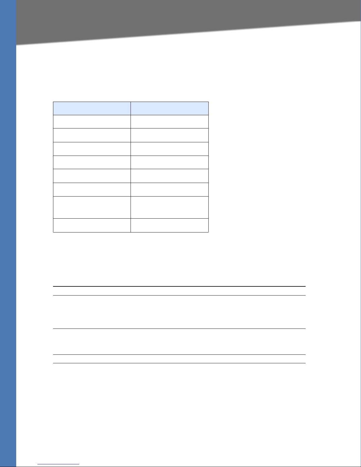
This guide supports the following firmware releases. The installed firmware must be at least the
indicated in the table below.
Product Firmware Version
PAP2T 5.1.6
SPA2102 5.2.5
SPA3102 5.1.7
SPA8000 6.1.3
RTP300 3.1.24
WRP400 1.00.06
WAG54GP2 Model Version 1: 1.01.02
Model Version 2: 2.01.06
AG310 1.00.04
Document Conventions
The following are the typographic conventions used in this document.
Typographic Element Meaning
Boldface
Italic
Monospaced Font
May indicate either of the following:
• A user interface element that you need to click, select, or otherwise act
on
• A literal value to be entered in a field.
May indicate either of the following:
• A variable that should be replaced with a literal value.
• The name of a page, section, or field in the user interface
Indicates code samples or system output.
Linksys ATA Administration Guide viii

Document Purpose and Contents
Document Purpose and Contents
This document provides information that an administrator needs to configure the Linksys Voice
System, which typically consists of a SPA9000 IP PBX, one or more SPA900 Series IP phones, and
the optional SPA400 PSTN gateway and voice mail server. This guide focuses primarily on the
tasks that an administrator performs to configure a SPA9000 with the SPA9000 administration
web server.
NOTE: This guide does not cover initial installation and configuration, SPA900 Series phone
configuration, the Setup Wizard, or provisioning. See ”Related Documentation,” on page x.
The information in this guide is organized into the following chapters and appendices:
Chapter Contents
Chapter 1, "Introducing
Linksys Analog Telephone
Adapters"
This chapter introduces the functionality of the Linksys ATA
devices and describes the features that are available.
Chapter 2, "Basic
Administration and
Configuration of Your Linksys
ATA Device"
Chapter 3, "Configuring Your
System for ITSP
Interoperability"
Chapter 4, "Configuring Voice
Services"
Chapter 5, "Configuring Music
on Hold"
Chapter 6, "Configuring the
PSTN (FXO) Gateway"
Appendix A, "Linksys ATA
Routing Field Reference"
Appendix B, "Linksys ATA
Voice Field Reference"
Appendix C, "Provisioning
Reference (WRP400)"
This chapter describes the equipment and services that are
required to install your ATA device and explains how to
complete the basic administration and configuration tasks.
This chapter provides configuration details for the purpose of
helping you to ensure that your infrastructure properly
supports voice services.
This chapter describes how to configure your ATA device to
meet the customer’s requirements for voice services.
This chapter explains how to configure Music on Hold using
either a music file or streaming audio.
This chapter describes how to configure the Linksys SPA3102
and AG310 devices to provide PSTN connectivity.
This chapter describes the settings that you can configure
under the Router and Network tabs in the administration web
server pages.
This chapter describes the settings that you can configure
under the Voice tab in the administration web server pages.
The WRP400 can be provisioned remotely. This chapter
provides information about the parameters that can be
provisioned from an XML profile by using the Linksys profile
compiler tool (SPC).
Appendix D,
"Troubleshooting"
Appendix E, "Environmental
Specifications"
Appendix F, "Warranty
Information"
Linksys ATA Administration Guide ix
This appendix provides solutions to problems that may occur
during the installation and operation of the Linksys ATA
devices.
These appendices provide additional product information.

Related Documentation
Appendix I, "Software License
Agreement"
Appendix H, "Safety
Information"
Appendix J, "Contacts"
Related Documentation
Refer to the following documentation to provide additional information about features and
functionality of Linksys ATAs:
• Your Linksys ATA Quick Installation Guide
• Your Linksys ATA User Guide
• SPA Provisioning Guide
Linksys ATA Administration Guide is part of a complete suite of documentation that is
The
available to assist you in using and configuring Linksys devices. The following documents are of
special interest to Linksys Voice System administrators.
NOTE: These documents and more are available at Linksys.com.
Document Title Description Intended Audience
Linksys Phone Administration
Guide
Linksys SPA9x2 Phone User
Guide
Linksys Voice System
Installation and
Configuration Guide
• Configuration and
management of IP phones
• Deployment options with or
without the SPA9000 IP PBX
• SPA9x2 series IP phones
• Phone setup
• Phone features
• SPA9x2 series IP phones
•Network design
considerations and site
preparation
• Switch configuration
• Initial installation and
configuration of the LVS
components: SPA9000,
SPA400, SPA900 series IP
phones.
VARs and Service Providers
VARS and phone end-users
VARs and Service Providers
Linksys ATA Administration Guide x
Online Resources
Document Title Description Intended Audience
Linksys Voice System
Administration Guide
Linksys Provisioning Guide
• Administration and
configuration of system
features using the SPA9000
and SPA400
• Deployment options for ITSP,
PSTN, and ISDN services
• SPA9000, SPA400, SPA900
series phones
• Provisioning LVS components
VARs and Service Providers
Service Providers only
Online Resources
Website addresses in this document are listed without http:// in front of the address because
most current web browsers do not require it. If you use an older web browser, you may have to
add http:// in front of the web address.
Resource Link
Linksys www.linksys.com
Linksys International
Glossary www.linksys.com/glossary
www.linksys.com/international
Network Security www.linksys.com/security
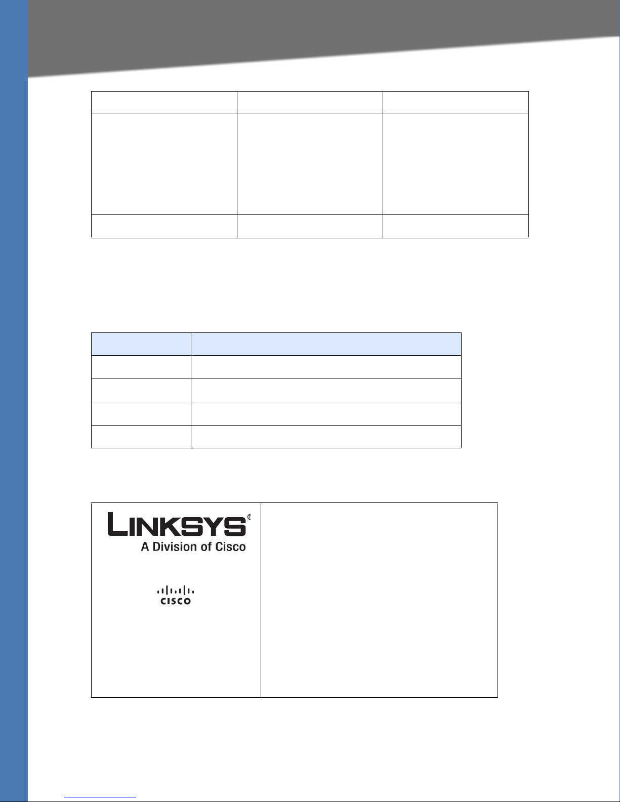
Copyright and Trademarks
Linksys is a registered trademark or trademark of
Cisco Systems, Inc. and/or its affiliates in the U.S.
and certain other countries. Copyright © 2008
Cisco Systems, Inc. All rights reserved.
Adobe, Acrobat, and Flash are either registered
trademarks or trademarks of Adobe Systems
Incorporated in the United States and/or other
countries. Other brands and product names are
trademarks or registered trademarks of their
respective holders.
Other brands and product names are trademarks
or registered trademarks of their respective
holders.
Technical Support
A list of technical support phone numbers and web sites is available in Appendix J, "Contacts."
Linksys ATA Administration Guide xi
Finding Information in PDF Files
Finding Information in PDF Files
Linksys documents are published as PDF files. The PDF Find/Search tool within Adobe® Reader®
lets you find information quickly and easily online. You can:
• Search an individual PDF.
• Search multiple PDFs at once (for example, all PDFs in a specific folder or disk drive).
• Perform advanced searches.
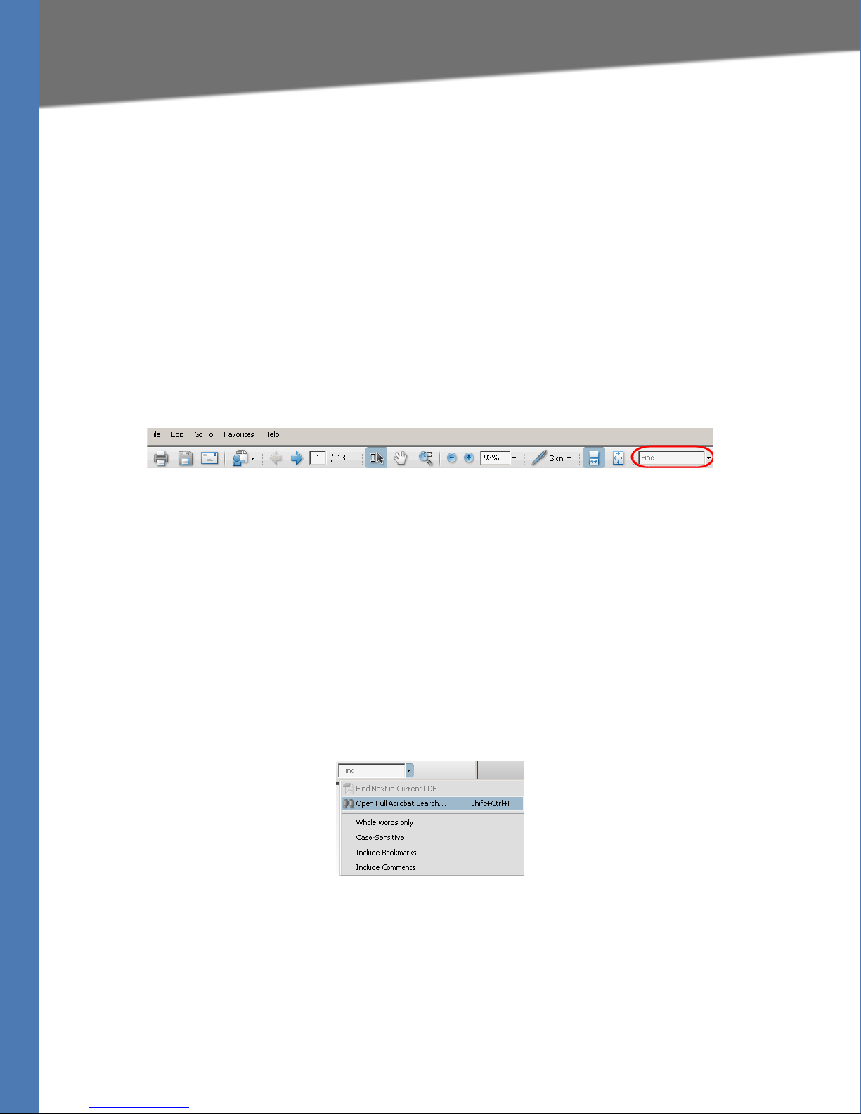
Finding Text in a PDF
1. Enter your search terms in the Find box on the toolbar.
NOTE: By default, the Find tool is available at the right end of the Acrobat toolbar. If the Find
tool does not appear, choose Edit > Find.
2. Optionally, click the arrow next to the Find text box to refine your search by choosing
special options such as Whole words only.
3. Press Enter. Acrobat displays the first instance of the search term. Press Enter again to
continue to more instances of the term.
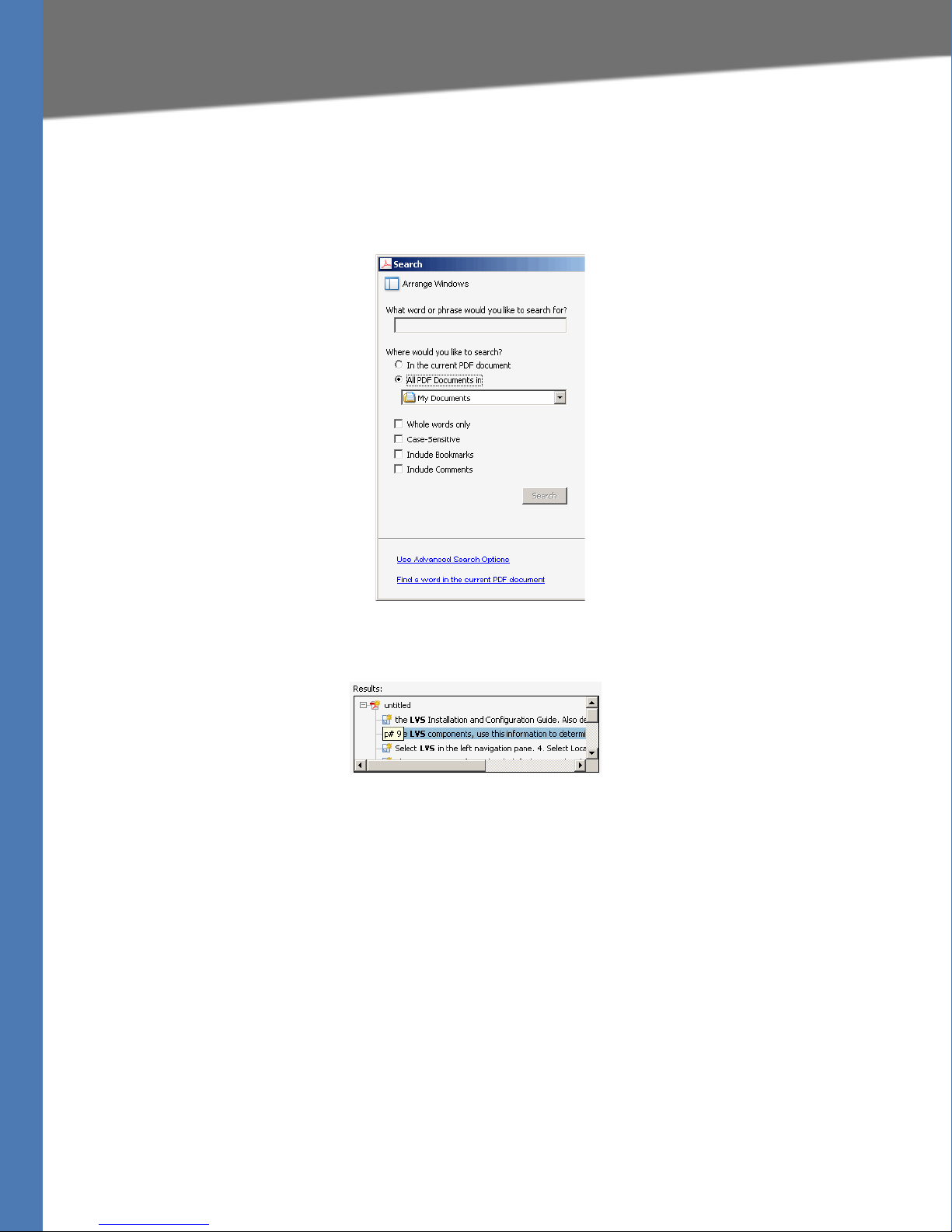
Finding Text in Multiple PDF Files
The Search window lets you search for terms in multiple PDF files that are stored on your PC or
local network. The PDF files do not need to be open.
1. Start Acrobat Professional or Adobe Reader.
2. Choose Edit > Search, or click the arrow next to the Find box and then choose Open Full
Acrobat Search.
3. In the Search window, complete the following steps:
a. Enter the text that you want to find.
b. Choose All PDF Documents in.
c. From the drop-down box, choose Browse for Location. Then choose the location on
your computer or local network, and click OK.
Linksys ATA Administration Guide xii
Finding Information in PDF Files
d. If you want to specify additional search criteria, click Use Advanced Search Options,
and choose the options you want.
e. Click Search.
4. When the Results appear, click + to open a folder, and then click any link to open the file
where the search terms appear.
NOTE: For more information about the Find and Search functions, see the Adobe Acrobat
online help.
Linksys ATA Administration Guide xiii
Introducing Linksys Analog Telephone Adapters
Linksys ATA
Telephone/fax
Ethernet
Broadband CPE
(DSL, cable,
fixed wireless)
Broadband
SIP proxy
Layer 3
IP infrastructure
PSTN
Voice
gateway
187254
V
V
V
1
Introducing Linksys Analog Telephone
Adapters
This guide describes the administration and use of Linksys analog telephone adapters (ATAs).
Linksys ATA devices are a key element in the end-to-end IP Telephony solution. A Linksys ATA
device provides user access to Internet phone services through one or more standard
telephone RJ-11 phone ports using standard analog telephone equipment. The Linksys ATA
device connects to a wide area IP network, such as the Internet, through a broadband (DSL or
cable) modem or router.
This chapter introduces the functionality of the Linksys ATA devices and describes the features
that are available.
Refer to the following topics:
• ”Comparison of ATA Devices” section on page 16
• ”Linksys ATA Connectivity Requirements” section on page 18
• ”ATA Software Features” section on page 22
Linksys ATA Administration Guide 15

Introducing Linksys Analog Telephone Adapters
Comparison of ATA Devices
Comparison of ATA Devices
Each Linksys ATA device is an intelligent low-density Voice over IP (VoIP) gateway that enables
carrier-class residential and business IP Telephony services delivered over broadband or highspeed Internet connections. A Linksys ATA device maintains the state of each call it terminates
and makes the proper reaction to user input events (such as on/off hook or hook flash). The
Linksys ATA devices use the Session Initiation Protocol (SIP) open standard so there is little or no
involvement by a “middle-man” server or media gateway controller. SIP allows interoperation
with all ITSPs that support SIP.
The following table summarizes the ports and features provided by the Linksys ATA devices
described in this document.
Product
Name
PA P2 T
SPA2102
SPA3102
SPA8000
RTP300
WRP400
WRTP54G
WAG54GP2
AG310
FXS
(Analog
Phone)
FXO
PSTN
Connect-
RJ-45
Internet
(WAN)
RJ-45
Ethernet
(LAN)
Configurable
Voice Lines
Description
ion
2—1— 2 Voice adapter with two
FXS ports.
2—1 1 2 Voice adapter with
router.
111 1 1 Voice adapter with
router and PSTN
connectivity.
8 — 1 Maintenance
only
2 — 1 4 2 IP router with two FXS
2 — 1 4 2 Wireless-G IP router with
2 — 1 4 2 Wireless-G IP router with
1 1 1 1 1 ADSL2+ gateway with
8Voice adapter with
support for up to eight
FXS devices. Supports
SIP Trunking for inbound
call routing to trunk
groups.
ports. Provides ATA
device functionality.
two FXS ports. Provides
ATA device functionality.
Can be remotely
provisioned.
two FXS ports. Provides
ATA device functionality.
VoIP and PSTN
connectivity. Provides
ATA device functionality.
NOTE: The information contained in this guide is not a warranty from Linksys, a division of
Cisco Systems, Inc. Customers planning to use Linksys ATA devices in a VoIP service deployment
are advised to test all functionality they plan to support before putting the Linksys ATA device
in service. By implementing Linksys ATA devices with the SIP protocol, intelligent endpoints at
the edges of a network perform the bulk of the call processing. This allows the deployment of a
large network with thousands of subscribers without complicated, expensive servers.
Linksys ATA Administration Guide 16
Introducing Linksys Analog Telephone Adapters
SPA3102
Broadband
router
Broadband
router
SPA8000,
PAP2T
DSL/cable
modem
WAG54GP2,
AG310
WRP400, RTP300,
WRTP54G, and
SPA2102
Ethernet/Wireless
LAN
Fax (up to 4
SPA8000)
Analog phone
(up to 8 with
SPA8000)
PSTN
Ethernet/Wired
LAN
Internet
187255
PSTN
Ethernet/Wireless
LAN
Comparison of ATA Devices
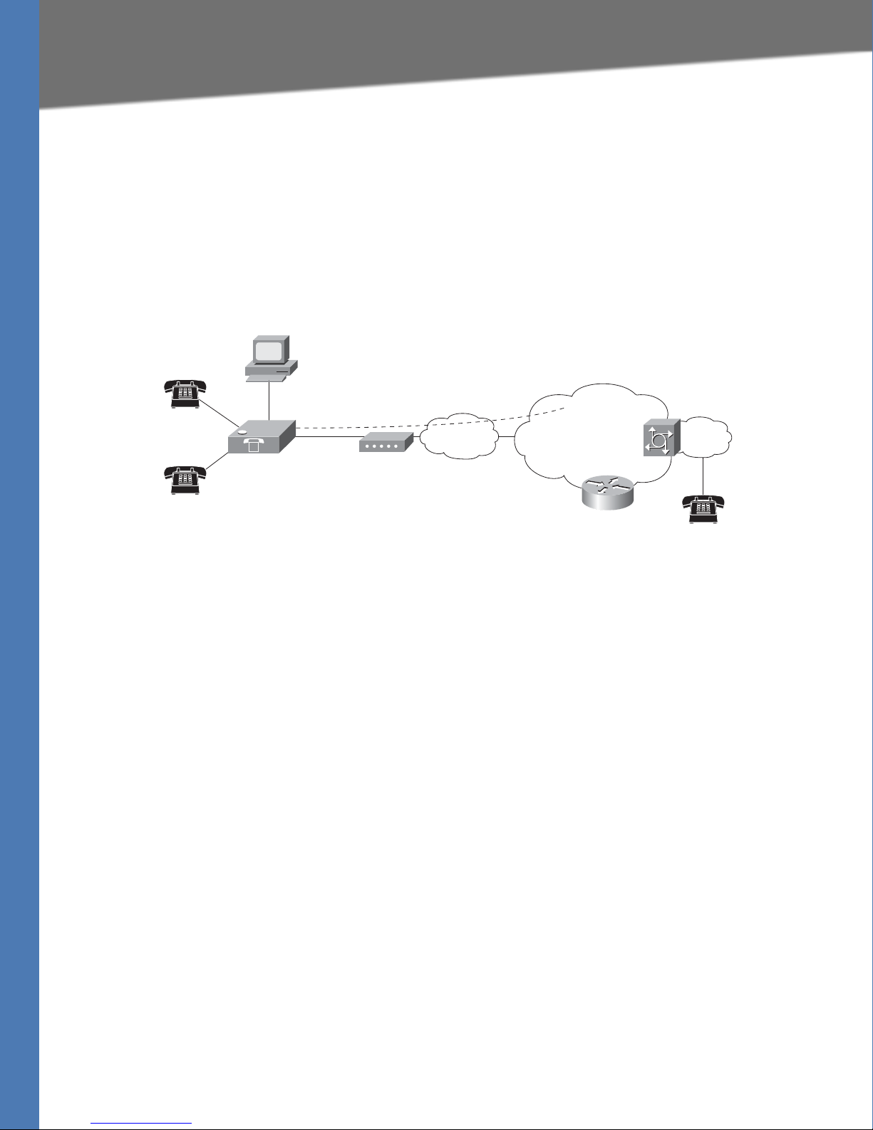
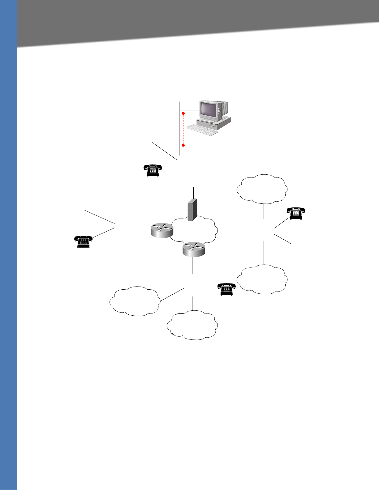
Figure 1 illustrates how the different Linksys ATA devices provide voice connectivity in a VoIP
network.
Figure 1: How Linksys ATAs Provide Voice Connectivity
Notes on Figure 1:
• The AG310, SPA3102, SPA8000, and WAG54GP2 act as SIP-PSTN gateways. They provide
PSTN connectivity in addition to a single FXS port. In addition, the AG310 and WAG54GP2
provide an ADSL2+ gateway.
• The WRP400, RTP300, and WRTP54G routers provide ports for analog telephone devices
and provide QoS in the form of priority packet queueing.
Linksys ATA Administration Guide 17

Introducing Linksys Analog Telephone Adapters
Line 1
Line 2
Internet
IP Router (with
hairpinning) or
Broadband mode
m
ITSP
ISP
PAP2T
LAN WAN
Ethernet
port
Administrative
IVR (Line 1 or
Line 2)
IP
IP
Linksys ATA Connectivity Requirements
Linksys ATA Connectivity Requirements
A Linksys ATA device can be connected to a local router, or directly to the Internet. Each phone
connected to an RJ-11 (analog) port on the Linksys ATA device connects to other devices
through SIP, which is transmitted over the IP network.
In order to ensure connectivity between the devices connected to its FXS ports, the Linksys ATA
device requires the following functionality to be supplied on the network connected to its
Ethernet port:
• Connection to an IP router with hairpinning support
• Connection to an outbound Proxy server
When a phone connected to the Linksys ATA device communicates with another phone, it
sends a SIP packet onto the internal LAN. The packet is then forwarded to the external LAN or
directly to the Internet. The source address and source port on the original packet are assigned
by the Linksys ATA device DHCP server. The address and port are translated by the Linksys ATA
device using Network Address Translation (NAT) and Port Address Translation (PAT). The packet
is then routed back to the internal network on the Linksys ATA device by the local router or the
ISP router.
Problems can occur with calls between phones connected to the Linksys ATA device when an
outbound proxy or a router with hairpinning support is not available. The Linksys ATA device
cannot directly connect the two telephone devices, but requires a local or remote router to
route the packet back to its destination on the local network from which it originated.
The necessary routing can be provided by a router with hairpinning support, or by an
outbound SIP proxy, which is typically provided by the Internet Telephony Service Provider
(ITSP). When relying on the ITSP for interconnecting phones on the Linksys ATA device, local
phones connected to the Linksys ATA device are unable to communicate with each other if the
Internet connection is not available for any reason. It is recommended you connect the Linksys
ATA device to a local router that provides hairpinning support to prevent this problem.
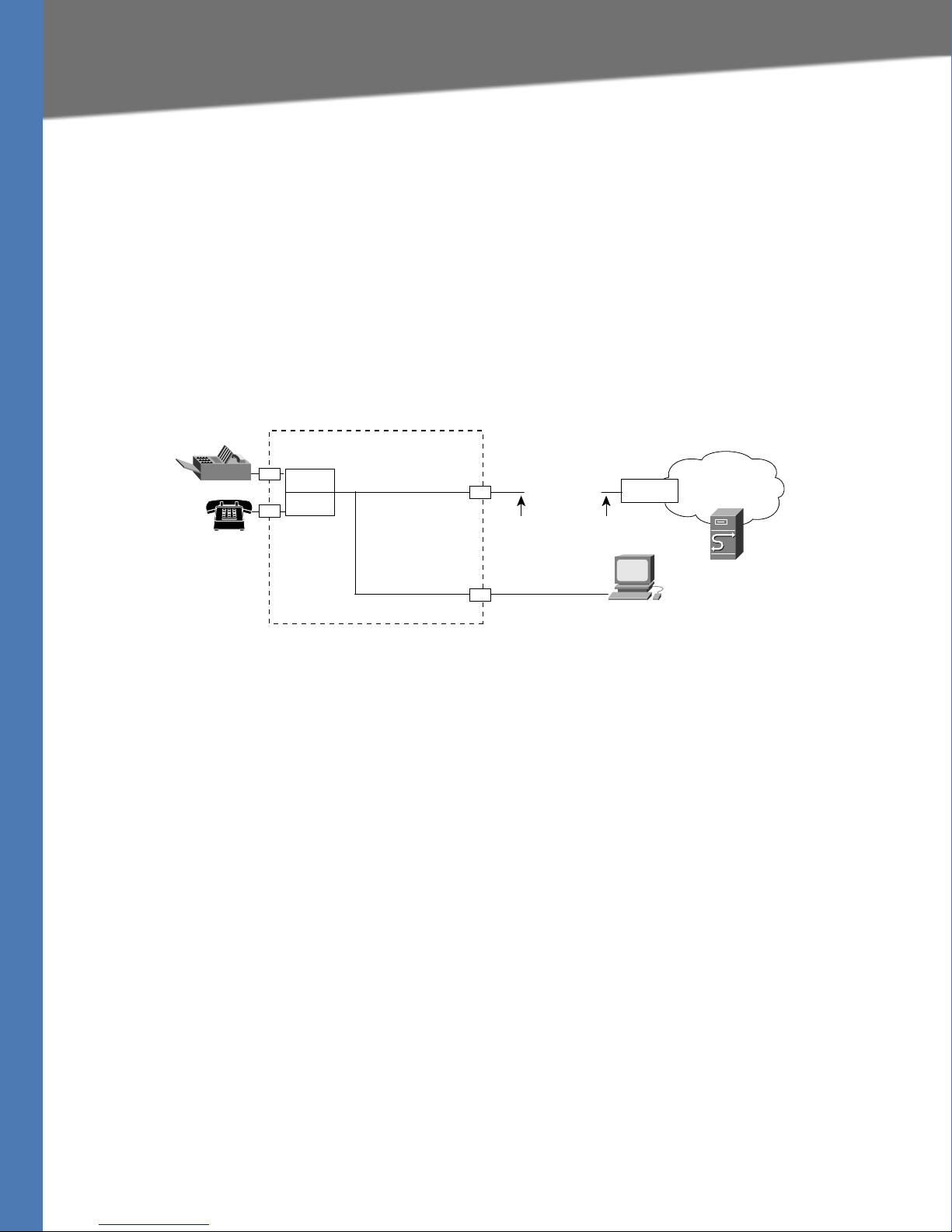
Linksys PAP2T Connectivity
As shown in the following figure, the PAP2T has two FXS ports (voice lines 1 and 2).
Linksys ATA Administration Guide 18
Introducing Linksys Analog Telephone Adapters
Line 1
Line 2
Internet
IP Router (with
hairpinning) or
Broadband mode
m
ITSP
ISP
SPA
2102
LAN
WAN
Ethernet
port
LAN
port
Administrative
IVR (Line 1 or
Line 2)
IP
IP
Administration
PC
187257
Linksys ATA Connectivity Requirements
Notes:
• The IVR functions are accessed by connecting an analog telephone to Line 1.
• For proper operation, the service provider should use an Outbound Proxy to forward all
voice traffic when the PAP2T is located behind a router. If necessary, explicit port ranges can
be specified for SIP and RTP.
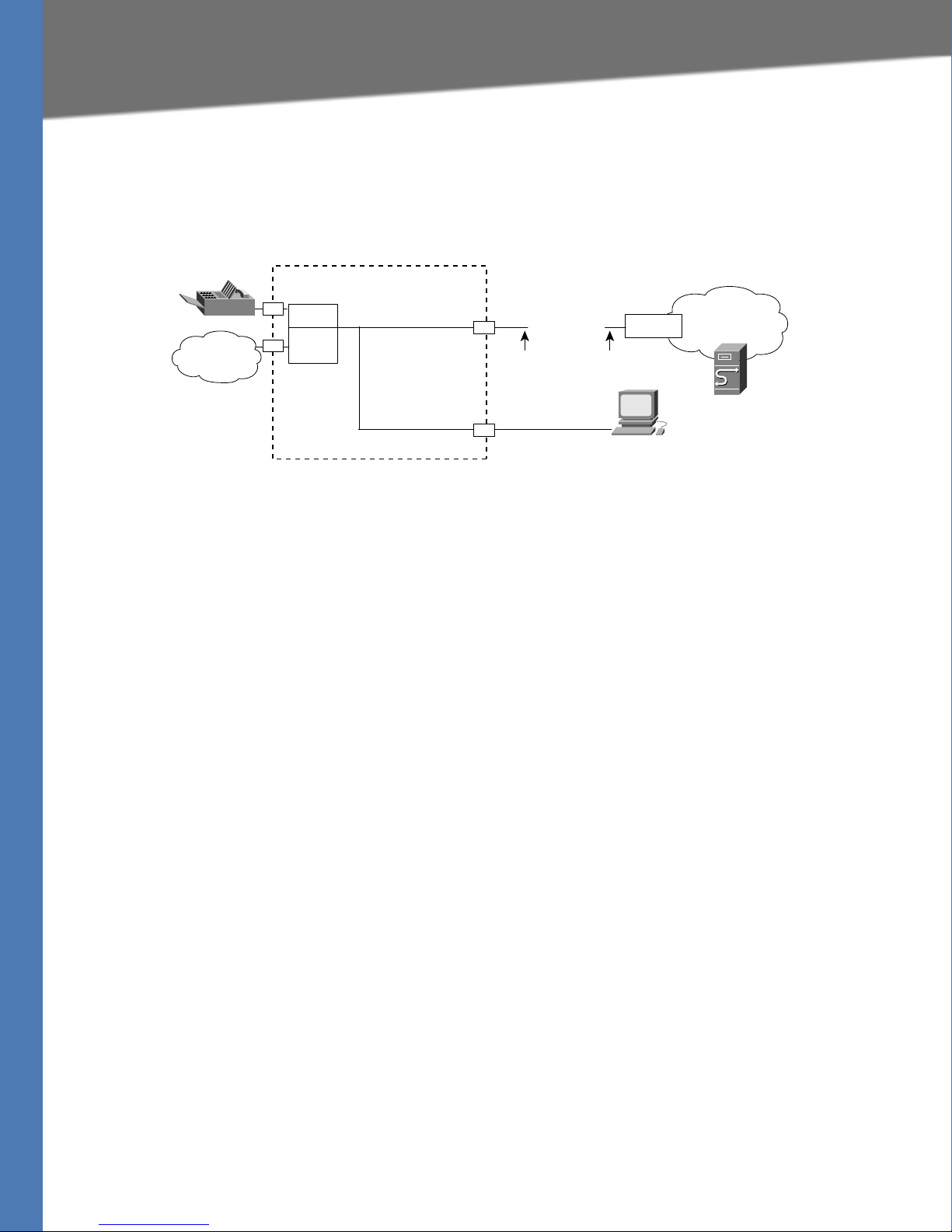
Linksys SPA2102 Connectivity
As shown in the following illustration, the SPA2102 has two FXS ports (voice lines 1 and 2).
By default, the device attached to the LAN port is assigned the network address 192.168.0.0
with a subnet mask of 255.255.255.0. If there is a network address conflict with a device on the
Ethernet port, the network address of the device on the LAN port is automatically changed to
192.168.1.0.
Notes:
• The IVR functions are accessed by connecting an analog telephone to Line 1.
• For proper operation, the service provider should use an Outbound Proxy to forward all
voice traffic when the SPA2102 is located behind a router. If necessary, explicit port ranges
can be specified for SIP and RTP.
Linksys ATA Administration Guide 19
Introducing Linksys Analog Telephone Adapters
Line 1
PSTN
Line 1
Internet
IP Router (with
hairpinning) or
Broadband mode
m
ITSP
ISP
SPA
3102
Ethernet
port
LAN
port
LAN WAN
Administrative
IVR (Line 1 or
Line 2)
IP
IP
Administration
PC
187259
PSTN
Linksys ATA Connectivity Requirements
Linksys SPA3102 Connectivity
As shown in the following figure, the SPA3102 has one FXS port (voice line 1).
By default, the device on the LAN port is assigned the network address 192.168.0.0 with a
subnet mask of 255.255.255.0. If there is a network address conflict with a device on the
Ethernet port, the network address of the device on the LAN port is automatically changed to
192.168.1.0.
Notes:
• The IVR functions are accessed by connecting an analog telephone to Line 1.
• For proper operation, the service provider should use an Outbound Proxy to forward all
voice traffic when the SPA3102 is located behind a router. If necessary, explicit port ranges
can be specified for SIP and RTP.
Linksys ATA Administration Guide 20
Introducing Linksys Analog Telephone Adapters
Line 1
Line 2
Internet
IP Router (with
hairpinning) or
Broadband modem
ITSP
ISP
SPA800
0
Line 4
Line 3
Line 6
Line 5
Line 8
Line 7
NAT/PAT
Internal DHCP
server
LAN WAN
Ethernet
port
AUX
port
Administrative
IVR (Line 1 or
Line 2
)
IP
IP
8 FXS (RJ-11/RJ-21 ) ports
Administration
PC
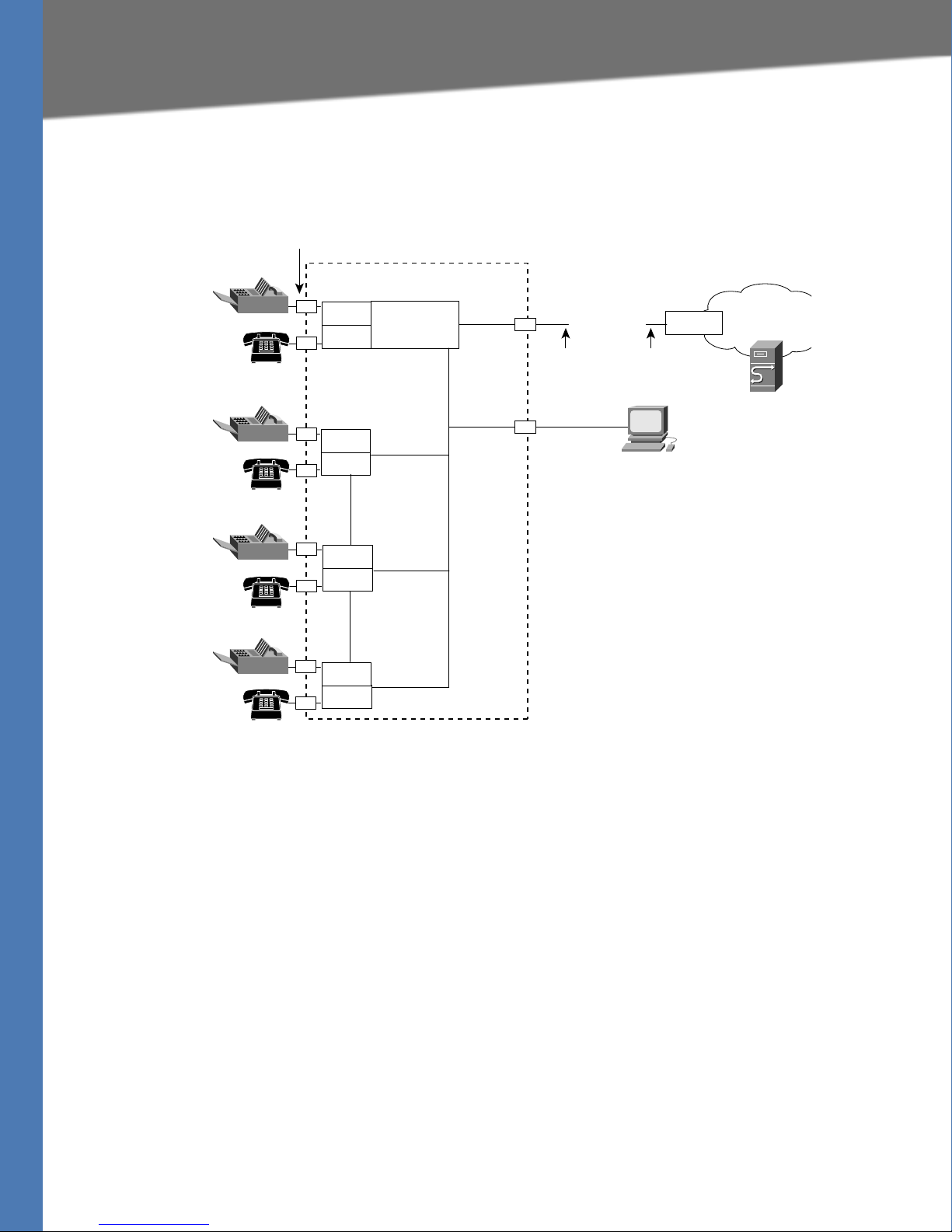
Linksys SPA8000 Connectivity
Linksys ATA Connectivity Requirements
As shown in the following illustration, the SPA8000 consists of eight voice ports
(voice lines 1-8).
By default, the device on the AUX port is assigned the network address 192.168.0.0 with a
subnet mask of 255.255.255.0. If there is a network address conflict with a device on the
Ethernet port, the network address of the device on the AUX port is automatically changed to
192.168.1.0.
In the illustration, one fax machine is connected to each pair of ports to illustrate that only one
T.38 connection is supported by each of the four pairs of RJ-11 ports. Up to four fax machines
can be connected to the SPA8000 router, but they must be distributed as shown.
Notes:
• With the SPA8000, use line 1 or line 2 to access the IVR functions. See the SPA8000 Quick
Installation Guide for IVR instructions.
• For proper operation, the service provider should use an Outbound Proxy to forward all
voice traffic when the SPA8000 is located behind a router. If necessary, explicit port ranges
can be specified for SIP and RTP.
• The SPA8000 is not designed to forward IP packets to devices connected to its AUX port and
that configuration is not supported.
• The SPA8000 also can be configured with trunk groups and trunk lines. See ”SIP Trunking
and Hunt Groups on the SPA8000,” on page 61.
Linksys ATA Administration Guide 21

Introducing Linksys Analog Telephone Adapters
ATA Softw are Featur es
ATA Software Features
The Linksys ATA device is a full featured, fully programmable phone adapter that can be custom
provisioned within a wide range of configuration parameters. This section contains a high-level
overview of features to provide a basic understanding of the feature breadth and capabilities of
the Linksys ATA device.
The following sections describe the factors that contribute to voice quality:
• ”Voice Supported Codecs,” on page 22
• ”SIP Proxy Redundancy,” on page 23
• ”Other Linksys ATA Software Features,” on page 23
Voice Supported Codecs
Negotiation of the optimal voice codec sometimes depends on the ability of the Linksys ATA
device to match a codec name with the codec used by the far-end device. The Linksys ATA
device allows the network administrator to individually name the various codecs that are
supported so that the Linksys ATA device can successfully negotiate the codec with the far-end
equipment. The administrator can select which low-bit-rate codec is to be used for each line.
G.711a and G.711u are always enabled. Configure your preferred codec in the (FXS) tab in the
Administration Web Server. See ”Linksys ATA Voice Field Reference,” on page 94. See also
”Supported Codecs,” on page 44 for a list of which codecs are supported on each Linksys ATA
device.
Codec (Voice Compression
Algorithm)
G.711 (A-law and mµ-law) This very low complexity codec supports uncompressed 64 kbps digitized
G.726 This low complexity codec supports compressed 16, 24, 32, and 40 kbps
G.729a The ITU G.729 voice coding algorithm is used to compress digitized speech.
G.723.1 The Linksys ATA device supports the use of ITU G.723.1 audio codec at 6.4
Description
voice transmission at one through ten 5 ms voice frames per packet. This
codec provides the highest voice quality and uses the most bandwidth of
any of the available codecs.
digitized voice transmission at one through ten 10 ms voice frames per
packet. This codec provides high voice quality.
Linksys supports G.729. G.729a is a reduced complexity version of G.729. It
requires about half the processing power to code G.729. The G.729 and
G.729a bit streams are compatible and interoperable, but not identical.
kbps. Up to two channels of G.723.1 can be used simultaneously. For
example, Line 1 and Line 2 can be using G.723.1 simultaneously, or Line 1 or
Line 2 can initiate a three-way conference with both call legs using G.723.1.
Note: The WRP400 device does not support the G.723.1 audio codec.
NOTE: When no static payload value is assigned per RFC 1890, the Linksys ATA device can
support dynamic payloads for G.726.
Linksys ATA Administration Guide 22

Introducing Linksys Analog Telephone Adapters
ATA Softw are Featur es
SIP Proxy Redundancy
In typical commercial IP Telephony deployments, all calls are established through a SIP proxy
server. An average SIP proxy server may handle thousands of subscribers. It is important that a
backup server be available so that an active server can be temporarily switched out for
maintenance. The Linksys ATA device supports the use of backup SIP proxy servers (via DNS
SRV) so that service disruption should be nearly eliminated.
A relatively simple way to support proxy redundancy is to configure your DNS server with a list
of SIP proxy addresses. The Linksys ATA device can be instructed to contact a SIP proxy server in
a domain named in the SIP message. The Linksys ATA device consults the DNS server to get a
list of hosts in the given domain that provides SIP services. If an entry exists, the DNS server
returns an SRV record that contains a list of SIP proxy servers for the domain, with their host
names, priority, listening ports, and so on. The Linksys ATA device tries to contact the list of
hosts in the order of their stated priority.
If the Linksys ATA device is currently using a lower priority proxy server, it periodically probes
the higher priority proxy to see whether it is back on line, and switches back to the higher
priority proxy when possible. SIP Proxy Redundancy is configured in the Line and PSTN Line
tabs in the Administration Web Server. See
”Linksys ATA Routing Field Reference,” on page 86.
Other Linksys ATA Software Features
The following table summarizes other features provided by Linksys ATA devices.
Feature Description
Streaming Audio Server See ”Configuring a Streaming Audio Server,” on page 71.
T.38 Fax Relay See ”Using a FAX Machine (SPA2102, SPA3102 or SPA8000),” on page 45.
Silence Suppression See ”Silence Suppression and Comfort Noise Generation,” on page 48.
Modem and Fax PassThrough
Adaptive Jitter Buffer The Linksys ATA device can buffer incoming voice packets to minimize out-
• Modem pass-through mode can be triggered only by predialing the
number set in the Modem Line Toggle Code. (Set in the Regional tab.)
• FAX pass-through mode is triggered by a CED/CNG tone or an NSE event.
• Echo canceller is automatically disabled for Modem pass-through mode.
• Echo canceller is disabled for FAX pass-through if the parameter FA X
Disable ECAN (Line 1 or 2 tab) is set to “yes” for that line (in that case FAX
pass-through is the same as Modem pass-through).
• Call waiting and silence suppression is automatically disabled for both
FAX and Modem pass-through. In addition, out-of-band DTMF Tx is
disabled during modem or fax pass-through.
of-order packet arrival. This process is known as jitter buffering. The jitter
buffer size proactively adjusts or adapts in size, depending on changing
network conditions.
The Linksys ATA device has a Network Jitter Level control setting for each line
of service. The jitter level determines how aggressively the Linksys ATA
device tries to shrink the jitter buffer over time to achieve a lower overall
delay. If the jitter level is higher, it shrinks more gradually. If jitter level is
lower, it shrinks more quickly.
Adaptive Jitter Buffer is configured in the Line and PSTN Line tabs. See
”Linksys ATA Voice Field Reference,” on page 94
.
Linksys ATA Administration Guide 23

Introducing Linksys Analog Telephone Adapters
ATA Softw are Featur es
Feature Description
International Caller ID
Delivery
Secure Calls A user (if enabled by service provider or administrator) has the option to
Adjustable Audio
Frames Per Packet
DTMF The Linksys ATA device may relay DTMF digits as out-of-band events to
Call Progress Tone
Generation
Call Progress Tone Pass
Through
Echo Cancellation Impedance mismatch between the telephone and the IP Telephony gateway
In addition to support of the Bellcore (FSK) and Swedish/Danish (DTMF)
methods of Caller ID (CID) delivery, Linksys ATAs provide a large subset of
ETSI-compliant methods to support international CID equipment.
International CID is configured in the Line and PSTN Line tabs. See ”Linksys
ATA Voice Field Reference,” on page 94
make an outbound call secure in the sense that the audio packets in both
directions are encrypted. See ”Secure Call Implementation” section on
page 57.
This feature allows the user to set the number of audio frames contained in
one RTP packet. Packets can be adjusted to contain from 1–10 audio frames.
Increasing the number of packets decreases the bandwidth utilized, but it
also increases delay and may affect voice quality. See the RTP Packet Size
parameter found in the SIP tab in the ”Linksys ATA Voice Field Reference,” on
page 94.
preserve the fidelity of the digits. This can enhance the reliability of DTMF
transmission required by many IVR applications such as dial-up banking and
airline information. DTMF is configured in the DTMF Tx Mode parameter
found in the Line tabs. See the ”Linksys ATA Voice Field Reference,” on
page 94.
The Linksys ATA device has configurable call progress tones. Call progress
tones are generated locally on the ATA device so an end user is advised of
status (such as ringback). Parameters for each type of tone (for instance a dial
tone played back to an end user) may include frequency and amplitude of
each component, and cadence information. See the Regional tab in the
”Linksys ATA Voice Field Reference,” on page 94.
This feature allows the user to hear the call progress tones (such as ringing)
that are generated from the far-end network. See the Regional tab in the
”Linksys ATA Voice Field Reference,” on page 94.
phone port can lead to near-end echo. The Linksys ATA device has a nearend echo canceller that compensates for impedance match. The Linksys ATA
device also implements an echo suppressor with comfort noise generator
(CNG) so that any residual echo is not noticeable. Echo Cancellation is
configured in the Regional, Line, and PSTN Line tabs. See ”Linksys ATA Voice
Field Reference,” on page 94
.
.
Linksys ATA Administration Guide 24

Introducing Linksys Analog Telephone Adapters
ATA Softw are Featur es
Feature Description
Signaling Hook Flash
Event
Configurable Dial Plan
with Interdigit Timers
Polarity Control The Linksys ATA device allows the polarity to be set when a call is connected
Calling Party Control Calling Party Control (CPC) signals to the called party equipment that the
Report Generation and
Event Logging
Syslog and Debug
Server Records
The Linksys ATA device can signal hook flash events to the remote party on a
connected call. This feature can be used to provide advanced mid-call
services with third-party-call-control. Depending on the features that the
service provider offers using third-party-call-control, the following Linksys
ATA features may be disabled to correctly signal a hook-flash event to the
softswitch:
• Call Waiting Service (parameter call waiting serv set in the Line tab)
• Three Way Conference Service (parameter three-way conf serv set in the
Line tab)
• Three Way Call Service (parameter three-way call serv set in the Line tab)
You can configure the length of time allowed for detection of a hook flash
using the Hook Flash Timer parameter on the Regional tab of the
administration web server. See ”Linksys ATA Voice Field Reference,” on
page 94
The Linksys ATA device has three configurable interdigit timers:
Initial timeout (T)—Signals that the handset is off the hook and that no digit
has been pressed yet.
Long timeout (L)—Signals the end of a dial string; that is, no more digits are
expected.
Short timeout (S)—Used between digits; that is after a digit is pressed a short
timeout prevents the digit from being recognized a second time.
See ”Configuring Dial Plans,” on page 49 for more information.
and when a call is disconnected. This feature is required to support some pay
phone system and answering machines. Polarity Control is configured in the
Line and PSTN Line tabs. See ”Linksys ATA Voice Field Reference,” on page 94
calling party has hung up during a connected call by removing the voltage
between the tip and ring momentarily. This feature is useful for auto-answer
equipment, which then knows when to disengage. CPC is configured in the
Regional, Line, and PSTN Line tabs. See ”Linksys ATA Voice Field Reference,”
on page 94
The Linksys ATA device reports a variety of status and error reports to assist
service providers to diagnose problems and evaluate the performance of
their services. The information can be queried by an authorized agent, using
HTTP with digested authentication, for instance. The information may be
organized as an XML page or HTML page. Report Generation and Event
Logging are configured in the System, Line, and PSTN Line tabs. See ”Linksys
ATA Voice Field Reference,” on page 94
Syslog and Debug Sever Records log more details than Report Generation
and Event Logging. Using the configuration parameters, the Linksys ATA
device allows you to select which type of activity/events should be logged.
Syslog and Debug Server allow the information captured to be sent to a
Syslog Server. Syslog and Debug Server Records are configured in the
System, Line, and PSTN Line tabs. See ”Linksys ATA Voice Field Reference,” on
page 94
.
.
.
.
.
Linksys ATA Administration Guide 25

Introducing Linksys Analog Telephone Adapters
ATA Softw are Featur es
Feature Description
SIP Over TCP To guarantee state-oriented communications, Linksys SPA2102 and SPA3102
devices allow you to choose TCP as the transport protocol for SIP. This
protocol is “guaranteed delivery”, which assures that lost packets are
retransmitted. TCP also guarantees that the SIP packages are received in the
same order that they were sent. As a result, TCP overcomes the main
disadvantages of UDP. In addition, for security reasons, most corporate
firewalls block UDP ports. With TCP, new ports do not need to be opened or
packets dropped, because TCP is already in use for basic activities such as
Internet browsing or e-commerce. SIP over TCP is configured in the Line tabs.
See ”Linksys ATA Voice Field Reference,” on page 94
SIP Over TLS Linksys SPA2102 and SPA3102 devices allow the use of SIP over Transport
Layer Security (TLS). SIP over TLS is designed to eliminate the possibility of
malicious activity by encrypting the SIP messages of the service provider and
the end user. SIP over TLS relies on the widely-deployed and standardized
TLS protocol. SIP Over TLS encrypts only the signaling messages and not the
media. A separate secure protocol such as Secure Real-Time Transport
Protocol (SRTP) can be used to encrypt voice packets. SIP over TLS is
configured in the SIP Transport parameter configured in the Line tab(s). See
”Linksys ATA Voice Field Reference,” on page 94
Media Loopback Linksys SPA2102, SPA3102, and PAP2T devices allow service providers to use
media loopback to quantitatively and qualitatively measure the voice quality
experienced by the end user. One device acts as the audio transmitter and
receiver while the other device acts as the audio mirror. The audio mirror
transmits the audio packets that it receives back to the transmitter/receiver
instead of transmitting the data sampled on its local microphone (IP phone)
or attached analog telephone (ATA-type device). Media loopback is
configured in the User tab. See ”Linksys ATA Voice Field Reference,” on
.
the Register Retry Intvl parameter when retrying a SIP REGISTER after a
failure. The default is 0, which disables this feature.
add to the Register Retry Long Intvl parameter when retrying a SIP
REGISTER after a failure. The default is 0, which disables this feature.
off retry delay. The exponential back-off retry delay starts with the
setting found in the Register Retry Intvl parameter and doubles it on
every REGISTER retry after a failure. In other words, the retry interval after
a failure is always set to the seconds configured in the Register Retry Intvl
parameter. If this feature is enabled, the Reg Retry Random Delay setting
is added on top of the exponential back-off adjusted delay value. The
default value is 0, which disables the exponential back-off feature.
.
Register Retry
Enhancements
page 94
The Register Retry Enhancements feature for Linksys SPA2102, SPA3102, and
PAP2T devices adds flexibility to the delay timers that are activated when the
SIP REGISTER of a device fails. Once a SIP REGISTER failure response code is
sent, a delay timer is selected depending on the type of registration failure
response code. The delay timers can be one of the following:
• Reg Retry Random Delay—Random delay range (in seconds) to add to
• Reg Retry Long Random Delay—Random delay range (in seconds) to
• Reg Retry Intvl Cap—The maximum value to cap the exponential back-
Register Retry is configured in the SIP tab. See ”Linksys ATA Voice Field
Reference,” on page 94
.
.
Linksys ATA Administration Guide 26

Introducing Linksys Analog Telephone Adapters
Feature Description
DHCP Renewal on
Timeout
Linksys SPA2102, SPA3102, and PAP2T voice devices typically operate in a
network where a DHCP server assigns IP addresses to the devices. Because IP
addresses are a limited resource, the DHCP server periodically renews the
device lease on the IP address. Therefore, if a Linksys ATA device loses its IP
address for any reason, or if some other device on the network is assigned its
IP address, the communication between the SIP proxy and the device is
either severed or degraded.
Whenever an expected SIP response is not received within a programmable
amount of time after the corresponding SIP command is sent, the DHCP
Renewal on Timeout feature automatically causes the device to request a
renewal of its IP address. If the DHCP server returns the IP address that it
originally assigned to the device, the Linksys ATA device is presumed to be
operating correctly. If it returns a different address, the ATA device changes
its IP address to the new address provided by the DHCP server. The Linksys
ATA device then resets, and once again sends a SIP register request for the
DHCP server to accept.
ATA Softw are Featur es
Linksys ATA Administration Guide 27

Basic Administration and Configuration of Your Linksys ATA
2
Basic Services and Equipment Required
Basic Administration and Configuration of
Your Linksys ATA Device
This chapter describes the equipment and services that are required to install your ATA device
and explains how to complete the basic administration and configuration tasks.
Refer to the following topics:
”Basic Services and Equipment Required” section on page 28
•
• ”Downloading Firmware” section on page 29
• ”Basic Installation and Configuration” section on page 30
• ”Upgrading the Firmware for the Linksys ATA Device” section on page 30
• ”Setting up Your Linksys ATA Device” section on page 31
• ”Using the Administration Web Server” section on page 31
• ”Upgrading, Rebooting, and Resyncing Your Linksys ATA Device” section on page 34
• ”Provisioning Your Linksys ATA Device” section on page 35
Basic Services and Equipment Required
To configure your Linksys ATA devices, you need the following services and equipment:
• An integrated access device or modem for broadband access to the Internet
• Internet Telephony Service Provider (ITSP) for Voice Over IP Telephone service
• You must have to following information about your account:
– SIP Proxy (IP address or name)
– Account information and Password
• Computer with Microsoft Windows XP or Windows Vista (for system configuration)
•Analog phones
• UPS (uninterruptible Power Source) recommended for devices such as the Integrated
Access Device, network switch, router, and PoE switch to ensure that your phone system
continues to work during a power failure, just like your home phone.
Linksys ATA Administration Guide 28
Basic Administration and Configuration of Your Linksys ATA
Downloading Firmware
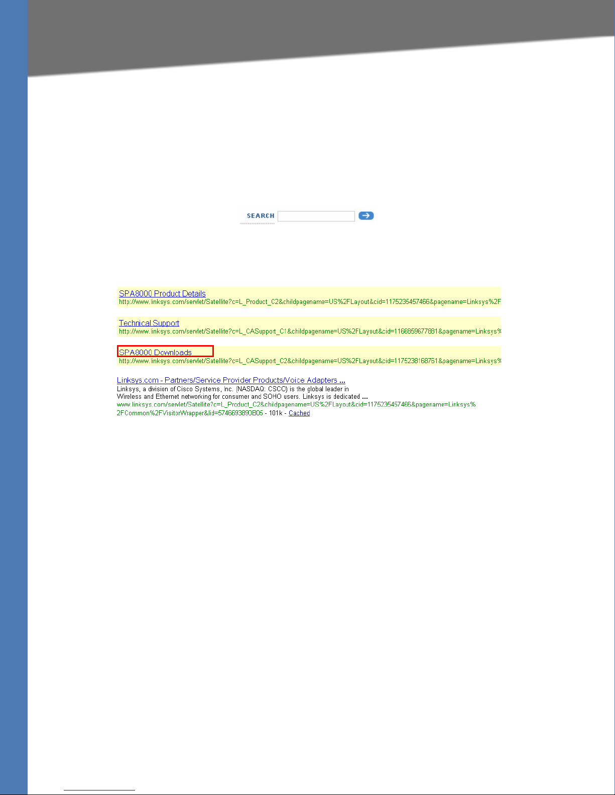
Downloading Firmware
Always download and install the latest firmware for your Linksys ATA device before doing any
configurations.
1. Direct your browser to the following URL: http://www.linksys.com
2. In the
3. In the search results list, click the Downloads link for your product. Refer to the following
4. When the
Search box near the top right corner of the page, type the model number of your
Linksys ATA device.
example.
Downloads page appears choose your product version from the Version drop-
down list., if the page includes a
Version prompt.
5. Under Firmware, click the link for the latest version of the firmware.
NOTE: If you are using Windows XP Service Pack 2 (SP2) and Internet Explorer, you may see
the “Pop-up blocked” message in your browser information bar. If you see this message, click
the information bar and select Temporarily Allow Pop-ups. Then click the link again.
6. Click Save in the File Download dialog box that appears.
7. In the Save As dialog box, choose a location for the file and then click Save.
8. When the download is complete, if prompted, click Close.
The name of the file depends on the firmware file of your device. If the firmware file you
download is in zip format, double-click the file and extract its contents to a single folder or to
the desktop. To extract the firmware file from the archive, use a utility such as WinZip, or use the
built-in decompression features of Windows XP.
Linksys ATA Administration Guide 29

Basic Administration and Configuration of Your Linksys ATA
Basic Installation and Configuration
Basic Installation and Configuration
See your particular Linksys ATA device’s Quick Installation Guide and User Guide for
instructions. If you are configuring the complete Linksys Voice System, also refer to the
Installation and Configuration Guide
.
LVS
Upgrading the Firmware for the Linksys ATA Device
In this procedure, you install the firmware files that you downloaded previously.
1. Determine the address of the Linksys ATA device:
a. Connect an analog telephone to the Phone 1 or Phone 2 port on the ATA device.
b. Press **** on the keypad to access the IVR menu.
c. Press 110# to determine the Internet (WAN) IP address.
2. Make a note of the IP address that is announced.
NOTE: If the administration computer is connected to the Ethernet port of the Linksys ATA
device, the default IP address is 192.168.0.1.
3. Use the administration computer to install the latest firmware:
a. Extract the Zip file, and then run the executable file to upgrade the firmware.
b. When the Firmware Upgrade Warning window appears, click Continue.
c. In the next window that appears, enter the IP address of the Linksys ATA device, and
then click OK.
d. In the Confirm Upgrade window, verify that the correct device information and product
number appear. Then click Upgrade.
e. A progress message appears while the upgrade is in progress. The success window
appears when the upgrade is completed. The device reboots.
f. Click OK to close the confirmation message.
g. To verify the upgrade, point the web browser to the IP address of the Linksys ATA device.
Check the Router > Status page. The Software Version field should show the firmware
version that you installed.
NOTE: You may need to refresh your browser to display the updated page reflecting the
new version number.
Linksys ATA Administration Guide 30
 Loading...