

Page 1
Package Contents
2300 Series Camera
•
Stand Kit
•
Power Supply (12V 1A)
•
6’ Ethernet Cable
•
Lens Adapter Ring
•
Allen Wrench
•
Quick Installation Guide
•
Setup CD
•
Antenna (WVC2300)
•
Business Internet
Video Camera with
Audio
Model: PVC2300, WVC2300
QUICK INSTALLATION
BUSINESS SERIES
Page 2

Page 3

Table of Contents
Minimum Requirements . . . . . . . . . . . . . . . . . . . . . . . . . . . . . . . . . . . . 4
Installation . . . . . . . . . . . . . . . . . . . . . . . . . . . . . . . . . . . . . . . . . . . . . . . . . 5
Configuration . . . . . . . . . . . . . . . . . . . . . . . . . . . . . . . . . . . . . . . . . . . . . . . 8
Adjusting the Lens . . . . . . . . . . . . . . . . . . . . . . . . . . . . . . . . . . . . . . . . .14
Online Resources
Website addresses in this document are listed without http:// in front of the
address because most current web browsers do not require it. If you use an
older web browser, you may have to add http:// in front of the web address.
Resource Website
Linksys www.linksys.com
Glossary www.linksys.com/glossary
Network Security www.linksys.com/security
Copyright and Trademarks
Linksys is a registered trademark or trademark of Cisco Systems, Inc. and/or its
affiliates in the U.S. and certain other countries. Copyright © 2007 Cisco Systems,
Inc. All rights reserved. Other brands and product names are trademarks or
registered trademarks of their respective holders.
3
Page 4

Minimum Requirements
Minimum System Requirements (for 1 camera):
CPU Pentium 4 class, 2GHz
Memory 1GB
Operating System Microsoft Windows 2000, XP or Vista
Hard Drive 30MB of available space
Graphics Card AGP with a minimum 64MB
Browser
Mozilla users must download ActiveX plug-in at http://www.iol.ie/~locka/mozilla/mozilla.htm†
4
Internet Explorer 6.0 (or above), Mozilla† Firefox, and
Netscape7.0 (or above)
Page 5
Installation1�
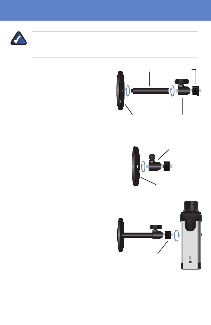
NOTE: Before attaching the camera extension or swivel head, the stand
base can be mounted in a permanent location by using three screws to
secure the stand base to the desired location.
The Camera stand can be
A.
connected two different ways:
Attach the stand base to the
camera extension and attach the
camera extension to the swivel
head.
You can connect the swivel head
directly to the stand base if the
extension isn’t necessary.
Connect the camera stand to the
B.
bottom of the camera. Adjust the
camera to the appropriate viewing
position.
Once the camera is positioned
properly, secure the camera in place
by tightening the locknut.
Camera Extension
Camera Extension
Stand Base
Stand Base
OR
OR
Swivel Head
Swivel Head
Stand Base
Stand Base
Locknut
Locknut
Locknut
Swivel Head
Swivel Head
5
Page 6

Installation
LINK/ACT
PoE
LINK/ACT
PoE LINK/ACT
Gigabit
LINK/ACT
GigabitLINK/ACT
PoE
LINK/ACT
PoE LINK/ACT
Gigabit
LINK/ACT
Gigabit
Connect the included Ethernet
C.
network cable to your network
router or switch.
Connect the other end of the cable
D.
to the Camera’s Ethernet port.
If your network switch provides
Power over Ethernet to the Camera,
verify the Camera’s LEDs are lit and
skip steps E-G.
Connect the included power
E.
adapter to the Camera’s Power
port and plug the other end into a
standard electrical outlet.
Verify that the Camera’s LEDs are lit.
6
Page 7

Installation
NOTE: Steps F and G on this page are only necessary if you are using
the WVC2300 Wireless-G Business Internet Video Camera.
Connect the antennas to the antenna connectors on the Camera.
F.
Place the antennas in an upright position.
G.
7
Page 8

Configuration2�
Insert the Setup CD into your
A.
CD-ROM drive. If the CD doesn’t run
automatically, go to My Computer
and click on your CD-ROM drive.
The Setup screen will appear. Click
B.
the Click Here to Start button.
The license agreement screen will
C.
appear, click Next if you agree and
wish to proceed.
8
Page 9

The Wizard will now search for your
D.
camera.
Once found highlight the camera
and click Next.
If the Camera you want is not
displayed in the Selection box, click
Search Again.
Installation
NOTE: The Camera defaults to
DHCP mode. If your network
doesn’t have a DHCP server or if
you are having issues obtaining
an IP address, you can assign a
static IP address to the Camera
by pressing the reset button
for less than 3 seconds. A static
IP address of 192.168.1.99 will
be assigned to the Camera.
WARNING: Pressing the reset button for 10 seconds will restore the
factory default settings, including setting the Camera to DHCP mode.
Reset ButtonReset Button
9
Page 10

Installation
The default username and
E.
password is admin. Type
admin in lowercase letters, in
the Administrator Name and
Administrator Password fields, then
click OK.
For security purposes, it is
recommended that you change the
default name and password using
the Camera’s web-based utility at a
later time.
On the Basic Settings screen,
F.
change the following settings:
Camera Name: Enter a unique
name for the Camera, up to 15
characters in length. Unique names
are helpful when you are using
multiple Cameras on the same
network.
Description: Enter a description,
up to 32 characters in length, with
additional information, such as the
location of the Camera.
Time Zone: Select the time zone
that corresponds with the Camera’s
location.
Date: Enter the current date in the
provided fields.
Time: Enter the current time in the
provided fields. When you have
finished making changes, click
Next.
10
Page 11

If you know your IP address,
G.
then select Static IP address,
otherwise leave the default setting,
Automatic Configuration DHCP.
The New Internet Camera Settings
H.
screen will appear and display the
Camera’s settings. Click Next to
continue or click Back to make
changes.
Installation
A confirmation window will appear,
I.
click OK to confirm the settings.
A timer will appear as the settings
are saved to the Camera.
A window will appear indicating
J.
that the settings have been saved
successfully. Click OK to continue.
11
Page 12

Installation
The Wizard will now return to
K.
the Welcome screen. Click Exit to
automatically launch your default
web browser and proceed to the
Home page login screen.
The login prompt will appear, enter
L.
admin in both the User name and
Password fields.
Internet Explorer will prompt you
M.
to install ActiveX. In order to view
video you must accept the ActiveX
download.
Click Install ActiveX Control.
12
Page 13

Click the Install button.
N.
Installation is complete!
You should be able to view video
on the home page.
Installation
13
Page 14

Adjusting the Lens3�
The Linksys Business Internet Video
Camera uses an adjustable CS
mount lens.
Adjust the focus by slowly rotating
the Camera Lens Focus clockwise or
counterclockwise.
Camera Lens Focus Used to
Camera Lens Focus Used to
adjust camera focus.
adjust camera focus.
Camera Base Does not move
Camera Base Does not move
Camera Lens Base Do not
NOTE: The resolution and
video quality can be adjusted
Camera Lens Base Do not
adjust unless you are removing
adjust unless you are removing
the lens to install another lens.
the lens to install another lens.
from the Audio/Video > Video
screen in the web-based utility.
Use the Camera Lens Focus to
fine tune the image.
Optional Lenses
Use any C/CS-mount lens or one of the following recommended lenses:
Model Description
CAMLWA CS/Mount Wide-angled Camera Lens
CAMLMI
CAMLAI
CS/Mount Manual Vari-focal
with Manual Iris Control Camera Lens
CS/Mount Vari-focal
with Auto Iris Control Camera Lens (10x Zoom)
CAMEE1
14
Ruggedized Outdoor Enclosure (IP66 certified)
with Heater and Blower
7052110NC-RR
Page 15

Page 16

For additional information or troubleshooting help, refer to the User Guide on the CD-ROM.
Additional support is also available via e-mail or by phone.
24-Hour Technical Support
800-326-7114
E-mail Support
support@linksys.com
Website
http://www.linksys.com
http://support.linksys.com
RMA (Return Merchandise Authorization)
http://www.linksys.com/support
FTP Site
ftp://ftp.linksys.com
Sales Information
800-546-5797 (800-LINKSYS)
www.linksys.com
 Loading...