

Page 1

USER GUIDE
EtherFast® 16-port and 24-port
10/100 Ethernet Switches
Models: EF3116, EF3124,
EF4116, and EF4124
Page 2
About This Guide
Icon Descriptions
While reading through the User Guide you may see
various icons that call attention to specific items. Below is
a description of these icons:
NOTE: This check mark indicates that there is
a note of interest and is something that you
should pay special attention to while using the
product.
WARNING: This exclamation point indicates
that there is a caution or warning and it is
something that could damage your property or
product.
About This Guide
WEB: This globe icon indicates a noteworthy
website address or e-mail address.
Online Resources
Website addresses in this document are listed without
http:// in front of the address because most current web
browsers do not require it. If you use an older web browser,
you may have to add http:// in front of the web address.
Resource Website
Linksys www.linksys.com
Linksys International www.linksys.com/international
Glossary www.linksys.com/glossary
Network Security www.linksys.com/security
Copyright and Trademarks
Linksys, Cisco and the Cisco Logo are
registered trademarks or trademarks of
Cisco Systems, Inc. and/or its affiliates
in the U.S. and certain other countries.
Copyright © 2008 Cisco Systems, Inc. All
rights reserved. Other brands and product
names are trademarks or registered
trademarks of their respective holders.
EtherFast® 16-Port and 24-Port 10/100 Ethernet Switches
i
Page 3

Table of Contents
Chapter 1: Product Overview 1
Features . . . . . . . . . . . . . . . . . . . . . . . . . . . . . . . . . . . . . . . . . . . . . . . . . . . 1
Chapter 2: Installation 2
Planning Your Network . . . . . . . . . . . . . . . . . . . . . . . . . . . . . . . . . . . . . . . . . . 2
Installing an Ethernet Switch . . . . . . . . . . . . . . . . . . . . . . . . . . . . . . . . . . . . . . 3
Reading an Ethernet Switch’s LED Display . . . . . . . . . . . . . . . . . . . . . . . . . . . . . . 3
Tips on Switching Your Network . . . . . . . . . . . . . . . . . . . . . . . . . . . . . . . . . . . . 4
Appendix A: Fiber Optic Modules
Installing a Fiber Optic Expansion Module. . . . . . . . . . . . . . . . . . . . . . . . . . . . . . 5
Reading a Fiber Module’s LED Display . . . . . . . . . . . . . . . . . . . . . . . . . . . . . . . . 6
(Models EF3116 & EF3124 ONLY) 5
Appendix B: Specications 7
EF3116, EF3124 . . . . . . . . . . . . . . . . . . . . . . . . . . . . . . . . . . . . . . . . . . . . . . . 7
EF4116, EF4124 . . . . . . . . . . . . . . . . . . . . . . . . . . . . . . . . . . . . . . . . . . . . . . . 7
Appendix C: Warranty Information 8
Limited Warranty. . . . . . . . . . . . . . . . . . . . . . . . . . . . . . . . . . . . . . . . . . . . . . 8
Appendix D: Regulatory Information 10
FCC Statement . . . . . . . . . . . . . . . . . . . . . . . . . . . . . . . . . . . . . . . . . . . . . . .10
Safety Notices. . . . . . . . . . . . . . . . . . . . . . . . . . . . . . . . . . . . . . . . . . . . . . . .10
Industry Canada Statement . . . . . . . . . . . . . . . . . . . . . . . . . . . . . . . . . . . . . . .10
User Information for Consumer Products Covered by EU Directive 2002/96/EC on Waste
Electric and Electronic Equipment (WEEE) . . . . . . . . . . . . . . . . . . . . . . . . . . . . . .11
Appendix E: Software License Agreement 15
Software in Linksys Products . . . . . . . . . . . . . . . . . . . . . . . . . . . . . . . . . . . . . .15
Software Licenses . . . . . . . . . . . . . . . . . . . . . . . . . . . . . . . . . . . . . . . . . . . . .15
EtherFast® 16-Port and 24-Port 10/100 Ethernet Switches
ii
Page 4

Chapter 1
Chapter 1: Product Overview
With advanced switching technology, the EtherFast®
10/100 Ethernet Switches will boost your network
performance with much more than just full duplex data
transfer and dedicated bandwidth. They feature nonblocking, wire-speed switching that forwards packets as
fast as your network can deliver them. Also included are
Address Learning and Aging to prevent data transfer errors
and Data Flow Control to help prevent packet collisions.
The rack mountable switches include an Expansion Port
that accepts an optional Fiber Module to let you grow
your network by linking to other switches in full duplex
mode up to 2000 meters (6560 feet) away. The compact
switches are small enough to fit into any crowded office.
No matter how intensive your network demands, the
EtherFast® 10/100 Ethernet Switches advanced chipsets
support your needs with an affordable and efficient
networking solution you can count on.
Product Overview
Features
16 or 24 autosensing 10/100 full duplex, auto MDI/ •
MDI-X ports
Some models feature optional 100BaseFX Fiber Optic •
Modules to connect multiple switches at high speed
as your network grows
Run blazing speeds up to 200Mbps •
Address Learning and Aging and Data Flow Control for •
enhanced transmission reliability
Perfect for Running 10BaseT, 100BaseTX and 100BaseFX •
Hardware Together Seamlessly
Data Flow Control Filters Out Faulty Data Packets •
Auto MDI/MDI-X •
Supports aging function, 802.3x Pause Frame for full •
duplex
Head of Line (HOL) blocking prevention •
Broadcast storm control avoids unnecessary bandwidth •
absorption
EtherFast® 16-Port and 24-Port 10/100 Ethernet Switches
1
Page 5

Chapter 2
Installation
Chapter 2: Installation
Planning Your Network
Building a Fast Ethernet network involves a few more
topology rules in addition to 10BaseT network rules.
These rules specify distance limitations and cabling
specifications. Data loss, collisions, and other network
problems causing down time are likely to result if the rules
below are not followed.
Use UTP Category 5 (EIA 568B, Cat 5) ethernet cabling •
with four twisted-pair wires and RJ-45 tips for all Fast
Ethernet connections.
Use the chart below to position any switches, hubs •
and workstations.
From To Max. Distance
Switch Switch or Hub* 100 meters
Hub* Hub* 5 meters
Configuration A shows one possible way to set up an
Ethernet Switch in a Fast Ethernet environment. Note
that an Ethernet Switch requires UTP Category 5 network
cabling for all its connections, like all Fast Ethernet network
hardware.
All of the workstations below can access all resources
on the network - 10Mbps users can access the 100Mbps
nodes, and vice versa. While allowing the 10Mbps and
100Mbps segments to communicate, an Ethernet Switch
optimizes data traffic by switching the data packets to
their destination through the quickest route possible,
which improves performance up to 80% even on the
faster 100Mbps network segment.
Switch or Hub Workstation 100 meters
*Hub refers to any type of 100Mbps hub, including regular hubs and
stackable hubs. A 10Mbps hub linked to another 10Mbps hub or a
10/100 hub can span up to 100 meters (328 feet).
No more than two hubs should be uplinked in a row in •
a Fast Ethernet network. A set of stacked hubs, which
must be stacked with a stacking cable, counts as one
hub or node on the network.
In Fast Ethernet, an Ethernet Switch acts as a repeater, •
regenerating data signals before passing them on to
the next device. Hubs cannot act as repeaters.
Configuration A
EtherFast® 16-Port and 24-Port 10/100 Ethernet Switches
2
Page 6

Chapter 2
Installation
Installing an Ethernet Switch
Rack Mounting an Ethernet Switch
Each Ethernet Switch is equipped with three mounting
holes on each side for rack mounting in a standard rack.
After screwing a mounting bracket into each side of an
Ethernet Switch, lift the Switch into your rack and secure
the brackets in place with additional screws (not supplied
by Linksys).
Connecting Nodes to an Ethernet Switch
An Ethernet Switch’s front panel has 16 or 24 standard RJ45 ports, depending upon the model, which can connect to
workstations, file servers, print servers, and other network
peripherals. Each port automatically detects port speed
and can operate in either half or full duplex mode. With
duplex detection, you can run speeds of 10Mbps, 20Mbps,
100Mbps, up to a maximum of 200Mbps.
Each cable connected to an Ethernet Switch must be a
UTP Category 5 ethernet network cable with RJ-45 tips,
and must not exceed 100 meters (328 feet) in length.
Ready-to-use network cabling with precrimped ends
are available at most computer retail stores.Automatic
Configuration - DHCP
Connecting PCs
Connect your PCs to an Ethernet Switch’s ports with
straight-through UTP Category 5 cabling. Plug the other
end of the Cat 5 cable into your PC’s network adapter.
Connecting to Other Switches, Hubs, Bridges and
Repeaters
Each port on an Ethernet Switch can also be used to uplink
to another switch, hub, bridge or repeater, serving as an
uplink port. These ports will automatically detect what
kind of cable is connected, either cross-over or straightthrough, and adjust for that cable.
Reading an Ethernet Switch’s LED Display
LED Display
An Ethernet Switch’s LED Display has a Power LED to
indicate when the unit is ON. There are two LEDs per
port: the Link/Activity (Link/Act) LED and the Full Duplex/
Collision (FDX/Col) LED. (An example of the LEDs is shown
above. The LEDs on the switch you purchased may vary
slightly.) See the chart below to find out what the status
of each LED denotes.
Front Panel LED Displays
LEDs
Network Status
LEDs Color Status
Solid light
Link/Act Green
Blinking light
Solid light
FDX/Col Yellow
Blinking light Collision
Power Green Solid light
Connection
Established
Transmitting/
Receiving
Full duplex
transfer mode
Displays power
status
Powering On an Ethernet Switch
Plug in an Ethernet Switch’s AC power cable. The Switch
will first run a diagnostic Self-Test, which just takes a
few seconds. After the test, the Power LED will light up
to indicate that the unit is powered on. As each node is
powered on, the corresponding port’s Link/Activity (Link/
Act) LED will light up.
When data is transmitted or received, the Link/Act LEDs
will flicker.
EtherFast® 16-Port and 24-Port 10/100 Ethernet Switches
3
Page 7

Chapter 2
Tips on Switching Your Network
Here are some of the ways an Ethernet Switch can help
you optimize your network speed.
Speed up Nodes From Your 10BaseT Network
In a 10BaseT network, connect your hubs, file servers and
key users such as managers and network administrators
directly to an Ethernet Switch to channel dedicated
bandwidth in full duplex mode to each station. An
Ethernet Switch can communicate with all its connections
simultaneously.
Conserving Bandwidth with 10Mbps & 100Mbps Segments
10BaseT and 100BaseTX hardware are not readily
compatible, but an Ethernet Switch can designate
network segments of different speeds. This allows you to
run one 10Mbps segment to serve users without a need
for considerable speed, and a faster 100Mbps segment
devoted to users who depend heavily on multimedia,
database, gaming, or other speed-intensive applications.
With switched segmentation, your 100Mbps users will not
lose efficiency because of the 10Mbps segment’s transfer
speed.
Installation
Run 10Mbps Peripherals in Your Fast Ethernet Network
Most of the network peripherals in place today run at
10Mbps, since 10BaseT has been the standard network
speed to date. These peripherals, designed to operate
at 10Mbps, cannot readily communicate with 100Mbps
equipment. A 10Mbps interface is also required for
cable and DSL connections, which are quickly becoming
very popular. An Ethernet Switch gives your 10BaseT
equipment and cable and DSL lines a 10Mbps interface
while still running your Fast Ethernet equipment at
100Mbps.
Strengthen Data Transfers Through Signal Regeneration
An Etherfast Switch functions as a repeater, which
regenerates data signals as they pass through it. This
feature acts as a safeguard to deter data loss and ensure
that transmissions arrive at their destination intact.
Switches positioned between hubs can preserve your
data’s integrity and eliminate your need to buy and use
repeaters in your Fast Ethernet network.
EtherFast® 16-Port and 24-Port 10/100 Ethernet Switches
4
Page 8

Appendix A
Fiber Optic Modules
Appendix A: Fiber Optic Modules (Models EF3116 & EF3124 ONLY)
IMPORTANT: Fiber Optic Modules will only
function with model numbers: EF3116 and
EF3124. If you are not sure of the Switch’s model
number, make sure there is a fiber optic module
port in the front of the Switch. If it does not
have a fiber optic module port, your Switch will
not function with Fiber Optic Modules.
Some Ethernet Switches are equipped with an expansion
port for adding optional fiber optic expansion modules.
The 100BaseFX Fiber Modules allow you to connect the
Ethernet Switch to other switches, hubs, or routers in
fiber optic network backbones. These modules use highbandwidth, multimode fiber optic cabling with SC type
connectors.
Use the guidelines below to plan the layout of your
network with other fiber-equipped devices from your
Switch’s 100BaseFX fiber module.
100BaseFX Fiber Cabling Distance Limitations
From To Duplex Max. Distance
Full
Switch or
Distance
Extender
The
Ethernet
Switch
Fiber
Transceiver
* A distance extender has an internal switch, whereas a
transceiver does not. Switches generally use distance
extenders, and hubs utilize both types of modules.
Half
Half only*
2000 meters
(6560 feet)
412 meters
(1350 feet)
208 meters
(682 feet)
Fiber cabling can transmit your Switch’s data up to 2000
meters (6560 feet) away to another switch without
requiring signal regeneration. The 100BaseFX SC Fiber
Module (model number EF31SC) is available through your
Linksys dealer.
Installing a Fiber Optic Expansion Module
To install a fiber module into the Ethernet Switch’s
expansion port, follow these instructions:
Before installing the fiber optic module, you must first 1.
power off the Switch by removing the AC power cord.
If the Switch is rack mounted, you should remove the
Switch from the rack temporarily until the fiber optic
module is installed.
Remove the faceplate from the unit by loosening the 2.
screws on either side with a screwdriver. Remove
the expansion module from its packaging. Keep the
screws for securing the fiber module to the Switch in
step 4.
Slide your fiber expansion module into the Switch. The 3.
module should fit snugly into the Switch’s expansion
port.
Secure the fiber module with the screws from the 4.
faceplate. You may now remount the Switch into its
rack if needed, then reconnect the AC power cable to
power on the Switch and resume normal operation.
Install your multimode fiber optic cabling from the 5.
module.
EtherFast® 16-Port and 24-Port 10/100 Ethernet Switches
5
Page 9
Appendix A
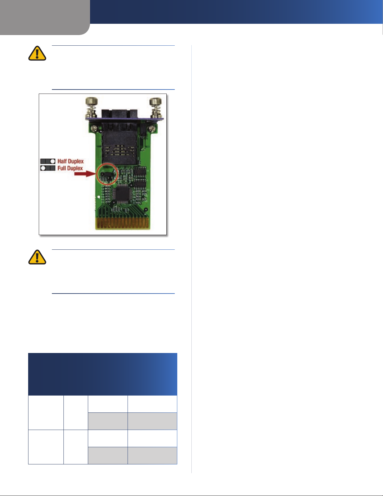
WARNING: The fiber module does not
autosense, so you must set it to run at either
full or half duplex. Prior to installing the fiber
module into the expansion port, use the
jumpers on the card as shown in Figure A-1.
Fiber Optic Modules
Jumper Diagram
WARNING: Changing connectors must be
done professionally with the proper tools. If
this is your first time working with fiber, consult
a networking professional who is familiar with
fiber.
Reading a Fiber Module’s LED Display
A Fiber Module’s LED Display has two LEDs: the Link/Activity
(Link/Act) LED and the Full Duplex/Half Duplex (FDX) LED.
See the chart below to find out what the status of each
LED denotes.
Front Panel LED Displays
LEDs
Network Status
LEDs Color Status
Solid light
Link/Act Green
Blinking light
Solid light
FDX Yellow
No light
Connection
Established
Transmitting/
Receiving
Full duplex
transfer mode
Half duplex
transfer mode
EtherFast® 16-Port and 24-Port 10/100 Ethernet Switches
6
Page 10

Appendix B
Specifications
Appendix B: Specifications
EF3116, EF3124
Standards IEEE 802.3, IEEE 802.3u,
IEEE 802.1p, IEEE 802.3x
Ports 16 or 24 10/100 Auto Negotiation RJ-45 Ports
One Fiber Module
Expansion Port
Speed Per Port 10Mbps or 100Mbps
(Half Duplex)
20Mbps or 200Mbps
(Full Duplex)
Cabling Type UTP/STP Category 5
or Better
LEDs Power
Link/Activity (per port)
Full Duplex (per port)
Environmental
Dimensions 7.1" x 1.75" x 16.93"
(180 x 44.5 x 430mm)
Weight EF3116: 88.16 oz (2500 g)
EF3124: 105.76 oz (3000 g)
Power 100-240V AC, 50-60Hz
Certication FCC Class A, CE
Operating Temp. 32 to 122ºF (0 to 50ºC)
Storage Temp. -40 to 158ºF (–40 to 70ºC)
Operating Humidity 20 to 95% noncondensing
Storage Humidity 20 to 95% noncondensing
EF4116, EF4124
Standards IEEE 802.3, IEEE 802.3u,
IEEE 802.3x
Ports 16 or 24 10/100 Auto Negotiation RJ-45 Ports
Speed Per Port 10Mbps or 100Mbps
(Half Duplex)
20Mbps or 200Mbps
(Full Duplex)
Cabling Type UTP/STP Category 5
or Better
LEDs Power
Link/Activity (per port)
Full Duplex/Collision
(per port)
Environmental
Dimensions 3.86” x 0.94” x 3.86”
(98 x 24 x 98mm)
Weight EF4114: 42.4 oz ( 1200 g)
EF4124: 45.92 oz (1300 g)
Power 100-240V AC, 50-60Hz
Certication FCC Class A, CE
Operating Temp. 32 to 122ºF (0 to 50ºC)
Storage Temp. -40 to 158ºF (–40 to 70ºC)
Operating Humidity 20 to 95% noncondensing
Storage Humidity 20 to 95% noncondensing
EtherFast® 16-Port and 24-Port 10/100 Ethernet Switches
Specications are subject to change without notice.
7
Page 11

Appendix C
Warranty Information
Appendix C: Warranty Information
Limited Warranty
Linksys warrants this Linksys hardware product against
defects in materials and workmanship under normal
use for the Warranty Period, which begins on the date of
purchase by the original end-user purchaser and lasts for
the period specified below:
One (1) year for new product •
Ninety (90) days for refurbished product •
This limited warranty is non-transferable and extends only
to the original end-user purchaser. Your exclusive remedy
and Linksys’ entire liability under this limited warranty
will be for Linksys, at its option, to (a) repair the product
with new or refurbished parts, (b) replace the product
with a reasonably available equivalent new or refurbished
Linksys product, or (c) refund the purchase price of the
product less any rebates. Any repaired or replacement
products will be warranted for the remainder of the
original Warranty Period or thirty (30) days, whichever is
longer. All products and parts that are replaced become
the property of Linksys.
Exclusions and Limitations
This limited warranty does not apply if: (a) the product
assembly seal has been removed or damaged, (b) the
product has been altered or modified, except by Linksys, (c)
the product damage was caused by use with non-Linksys
products, (d) the product has not been installed, operated,
repaired, or maintained in accordance with instructions
supplied by Linksys, (e) the product has been subjected to
abnormal physical or electrical stress, misuse, negligence,
or accident, (f) the serial number on the Product has been
altered, defaced, or removed, or (g) the product is supplied
or licensed for beta, evaluation, testing or demonstration
purposes for which Linksys does not charge a purchase
price or license fee.
ALL SOFTWARE PROVIDED BY LINKSYS WITH THE
PRODUCT, WHETHER FACTORY LOADED ON THE
PRODUCT OR CONTAINED ON MEDIA ACCOMPANYING
THE PRODUCT, IS PROVIDED “AS IS” WITHOUT WARRANTY
OF ANY KIND. Without limiting the foregoing, Linksys does
not warrant that the operation of the product or software
will be uninterrupted or error free. Also, due to the
continual development of new techniques for intruding
upon and attacking networks, Linksys does not warrant
that the product, software or any equipment, system or
network on which the product or software is used will be
free of vulnerability to intrusion or attack. The product
may include or be bundled with third party software or
service offerings. This limited warranty shall not apply to
such third party software or service offerings. This limited
warranty does not guarantee any continued availability
of a third party’s service for which this product’s use or
operation may require.
TO THE EXTENT NOT PROHIBITED BY LAW, ALL IMPLIED
WARRANTIES AND CONDITIONS OF MERCHANTABILITY,
SATISFACTORY QUALITY OR FITNESS FOR A PARTICULAR
PURPOSE ARE LIMITED TO THE DURATION OF THE
WARRANTY PERIOD. ALL OTHER EXPRESS OR IMPLIED
CONDITIONS, REPRESENTATIONS AND WARRANTIES,
INCLUDING, BUT NOT LIMITED TO, ANY IMPLIED
WARRANTY OF NON-INFRINGEMENT, ARE DISCLAIMED.
Some jurisdictions do not allow limitations on how long
an implied warranty lasts, so the above limitation may not
apply to you. This limited warranty gives you specific legal
rights, and you may also have other rights which vary by
jurisdiction.
TO THE EXTENT NOT PROHIBITED BY LAW, IN NO EVENT
WILL LINKSYS BE LIABLE FOR ANY LOST DATA, REVENUE
OR PROFIT, OR FOR SPECIAL, INDIRECT, CONSEQUENTIAL,
INCIDENTAL OR PUNITIVE DAMAGES, REGARDLESS OF THE
THEORY OF LIABILITY (INCLUDING NEGLIGENCE), ARISING
OUT OF OR RELATED TO THE USE OF OR INABILITY TO
USE THE PRODUCT (INCLUDING ANY SOFTWARE), EVEN
IF LINKSYS HAS BEEN ADVISED OF THE POSSIBILITY OF
SUCH DAMAGES. IN NO EVENT WILL LINKSYS’ LIABILITY
EXCEED THE AMOUNT PAID BY YOU FOR THE PRODUCT.
The foregoing limitations will apply even if any warranty
or remedy provided under this limited warranty fails of
its essential purpose. Some jurisdictions do not allow
the exclusion or limitation of incidental or consequential
damages, so the above limitation or exclusion may not
apply to you.
Obtaining Warranty Service
If you have a question about your product or experience a
problem with it, please go to www.linksys.com/support
where you will find a variety of online support tools and
information to assist you with your product. If the product
proves defective during the Warranty Period, contact
Linksys Technical Support for instructions on how to
obtain warranty service. The telephone number for Linksys
Technical Support in your area can be found in the product
User Guide and at www.linksys.com. Have your product
serial number and proof of purchase on hand when calling.
A DATED PROOF OF ORIGINAL PURCHASE IS REQUIRED
TO PROCESS WARRANTY CLAIMS. If you are requested to
return your product, you will be given a Return Materials
Authorization (RMA) number. You are responsible for
properly packaging and shipping your product to Linksys
at your cost and risk. You must include the RMA number
and a copy of your dated proof of original purchase when
returning your product. Products received without a RMA
number and dated proof of original purchase will be
EtherFast® 16-Port and 24-Port 10/100 Ethernet Switches
8
Page 12

Appendix C
rejected. Do not include any other items with the product
you are returning to Linksys. Defective product covered
by this limited warranty will be repaired or replaced and
returned to you without charge. Customers outside of
the United States of America and Canada are responsible
for all shipping and handling charges, custom duties,
VAT and other associated taxes and charges. Repairs or
replacements not covered under this limited warranty will
be subject to charge at Linksys’ then-current rates.
Technical Support
This limited warranty is neither a service nor a support
contract. Information about Linksys’ current technical
support offerings and policies (including any fees for
support services) can be found at:
www.linksys.com/support.
This limited warranty is governed by the laws of the
jurisdiction in which the Product was purchased by you.
Please direct all inquiries to: Linksys, P.O. Box 18558, Irvine,
CA 92623.
Warranty Information
EtherFast® 16-Port and 24-Port 10/100 Ethernet Switches
9
Page 13

Appendix D
Regulatory Information
Appendix D: Regulatory Information
FCC Statement
This product has been tested and complies with the
specifications for a Class B digital device, pursuant to Part
15 of the FCC Rules. These limits are designed to provide
reasonable protection against harmful interference in
a residential installation. This equipment generates,
uses, and can radiate radio frequency energy and, if not
installed and used according to the instructions, may
cause harmful interference to radio communications.
However, there is no guarantee that interference will not
occur in a particular installation. If this equipment does
cause harmful interference to radio or television reception,
which is found by turning the equipment off and on, the
user is encouraged to try to correct the interference by
one or more of the following measures:
Reorient or relocate the receiving antenna •
Increase the separation between the equipment or •
devices
Avis d’Industrie Canada
Cet appareil numérique de la classe B est conforme à la
norme NMB-003 du Canada.
Le fonctionnement est soumis aux conditions suivantes :
Ce périphérique ne doit pas causer d’interférences; 1.
Ce périphérique doit accepter toutes les interférences 2.
reçues, y compris celles qui risquent d’entraîner un
fonctionnement indésirable.
Connect the equipment to an outlet other than the •
receiver’s
Consult a dealer or an experienced radio/TV technician •
for assistance
Safety Notices
Caution: To reduce the risk of fire, use only No.26 AWG •
or larger telecommunication line cord.
Do not use this product near water, for example, in a •
wet basement or near a swimming pool.
Avoid using this product during an electrical storm. •
There may be a remote risk of electric shock from
lightning.
WARNING: This product contains lead, known
to the State of California to cause cancer, and
birth defects or other reproductive harm. Wash
hands after handling.
Industry Canada Statement
This Class B digital apparatus complies with Canadian
ICES-003.
Operation is subject to the following two conditions:
This device may not cause interference and1.
This device must accept any interference, including 2.
interference that may cause undesired operation of
the device.
EtherFast® 16-Port and 24-Port 10/100 Ethernet Switches
10
Page 14

Appendix D
Regulatory Information
User Information for Consumer Products Covered by EU Directive 2002/96/EC on Waste Electric and Electronic Equipment (WEEE)
This document contains important information for users
with regards to the proper disposal and recycling of
Linksys products. Consumers are required to comply with
this notice for all electronic products bearing the following
symbol:
English - Environmental Information for Customers in
the European Union
European Directive 2002/96/EC requires that the equipment
bearing this symbol on the product and/or its packaging must
not be disposed of with unsorted municipal waste. The symbol
indicates that this product should be disposed of separately
from regular household waste streams. It is your responsibility to
dispose of this and other electric and electronic equipment via
designated collection facilities appointed by the government or
local authorities. Correct disposal and recycling will help prevent
potential negative consequences to the environment and
human health. For more detailed information about the disposal
of your old equipment, please contact your local authorities,
waste disposal service, or the shop where you purchased the
product.
Български (Bulgarian) - Информация относно
опазването на околната среда за потребители в
Европейския съюз
Европейска директива 2002/96/EC изисква уредите, носещи
този символ върху изделието и/или опаковката му, да не
се изхвърля т с несортирани битови отпадъци. Символът
обозначава, че изделието трябва да се изхвърля отделно от
сметосъбирането на обикновените битови отпадъци. Ваша
е отговорността този и другите електрически и електронни
уреди да се изхвърлят в предварително определени от
държавните или общински органи специализирани пунктове
за събиране. Правилното изхвърляне и рециклиране
ще спомогнат да се предотвратят евентуални вредни за
околната среда и здравето на населението последствия. За
по-подробна информация относно изхвърлянето на вашите
стари уреди се обърнете към местните власти, службите за
сметосъбиране или магазина, от който сте закупили уреда.
Čeština (Czech) - Informace o ochraně životního
prostředí pro zákazníky v zemích Evropské unie
Evropská směrnice 2002/96/ES zakazuje, aby zařízení označené
tímto symbolem na produktu anebo na obalu bylo likvidováno
s netříděným komunálním odpadem. Tento symbol udává,
že daný produkt musí být likvidován odděleně od běžného
komunálního odpadu. Odpovídáte za likvidaci tohoto produktu
a dalších elektrických a elektronických zařízení prostřednictvím
určených sběrných míst stanovených vládou nebo místními
úřady. Správná likvidace a recyklace pomáhá předcházet
potenciálním negativním dopadům na životní prostředí a lidské
zdraví. Podrobnější informace o likvidaci starého vybavení si
laskavě vyžádejte od místních úřadů, podniku zabývajícího se
likvidací komunálních odpadů nebo obchodu, kde jste produkt
zakoupili.
Dansk (Danish) - Miljøinformation for kunder i EU
EU-direktiv 2002/96/EF kræver, at udstyr der bærer dette symbol
på produktet og/eller emballagen ikke må bortskaffes som
usorteret kommunalt affald. Symbolet betyder, at dette produkt
skal bortskaffes adskilt fra det almindelige husholdningsaffald.
Det er dit ansvar at bortskaffe dette og andet elektrisk og
elektronisk udstyr via bestemte indsamlingssteder udpeget
af staten eller de lokale myndigheder. Korrekt bortskaffelse
og genvinding vil hjælpe med til at undgå mulige skader for
miljøet og menneskers sundhed. Kontakt venligst de lokale
myndigheder, renovationstjenesten eller den butik, hvor du
har købt produktet, angående mere detaljeret information om
bortskaffelse af dit gamle udstyr.
Deutsch (German) - Umweltinformation für Kunden
innerhalb der Europäischen Union
Die Europäische Richtlinie 2002/96/EC verlangt, dass technische
Ausrüstung, die direkt am Gerät und/oder an der Verpackung mit
diesem Symbol versehen ist , nicht zusammen mit unsortiertem
Gemeindeabfall entsorgt werden darf. Das Symbol weist darauf
hin, dass das Produkt von regulärem Haushaltmüll getrennt
entsorgt werden sollte. Es liegt in Ihrer Verantwortung, dieses
Gerät und andere elektrische und elektronische Geräte über
die dafür zuständigen und von der Regierung oder örtlichen
Behörden dazu bestimmten Sammelstellen zu entsorgen.
Ordnungsgemäßes Entsorgen und Recyceln trägt dazu bei,
potentielle negative Folgen für Umwelt und die menschliche
Gesundheit zu vermeiden. Wenn Sie weitere Informationen zur
Entsorgung Ihrer Altgeräte benötigen, wenden Sie sich bitte an
die örtlichen Behörden oder städtischen Entsorgungsdienste
oder an den Händler, bei dem Sie das Produkt erworben haben.
EtherFast® 16-Port and 24-Port 10/100 Ethernet Switches
11
Page 15

Appendix D
Regulatory Information
Eesti (Estonian) - Keskkonnaalane informatsioon
Euroopa Liidus asuvatele klientidele
Euroopa Liidu direktiivi 2002/96/EÜ nõuete kohaselt on
seadmeid, millel on tootel või pakendil käesolev sümbol ,
keelatud kõrvaldada koos sorteerimata olmejäätmetega. See
sümbol näitab, et toode tuleks kõrvaldada eraldi tavalistest
olmejäätmevoogudest. Olete kohustatud kõrvaldama käesoleva
ja ka muud elektri- ja elektroonikaseadmed riigi või kohalike
ametiasutuste poolt ette nähtud kogumispunktide kaudu.
Seadmete korrektne kõrvaldamine ja ringlussevõtt aitab vältida
võimalikke negatiivseid tagajärgi keskkonnale ning inimeste
tervisele. Vanade seadmete kõrvaldamise kohta täpsema
informatsiooni saamiseks võtke palun ühendust kohalike
ametiasutustega, jäätmekäitlusfirmaga või kauplusega, kust te
toote ostsite.
Español (Spanish) - Información medioambiental para
clientes de la Unión Europea
La Directiva 2002/96/CE de la UE exige que los equipos que
lleven este símbolo en el propio aparato y/o en su embalaje
no deben eliminarse junto con otros residuos urbanos no
seleccionados. El símbolo indica que el producto en cuestión
debe separarse de los residuos domésticos convencionales con
vistas a su eliminación. Es responsabilidad suya desechar este y
cualesquiera otros aparatos eléctricos y electrónicos a través de
los puntos de recogida que ponen a su disposición el gobierno y
las autoridades locales. Al desechar y reciclar correctamente estos
aparatos estará contribuyendo a evitar posibles consecuencias
negativas para el medio ambiente y la salud de las personas. Si
desea obtener información más detallada sobre la eliminación
segura de su aparato usado, consulte a las autoridades locales,
al servicio de recogida y eliminación de residuos de su zona o
pregunte en la tienda donde adquirió el producto.
Ελληνικά (Greek) - Στοιχεία περιβαλλοντικής
προστασίας για πελάτες εντός της Ευρωπαϊκής
Ένωσης
Σύμφωνα με την Κοινοτική Οδηγία 2002/96/EC, ο εξοπλισμός που
φέρει αυτό το σύμβολο στο προϊόν ή/και τη συσκευασία του
δεν πρέπει να απορρίπτεται μαζί με τα μη διαχωρισμένα αστικά
απορρίμματα. Το σύμβολο υποδεικνύει ότι αυτό το προϊόν θα
πρέπει να απορρίπτεται ξεχωριστά από τα συνήθη οικιακά
απορρίμματα. Είστε υπεύθυνος για την απόρριψη του παρόντος
και άλλου ηλεκτρικού και ηλεκτρονικού εξοπλισμού μέσω των
καθορισμένων εγκαταστάσεων συγκέντρωσης απορριμμάτων,
οι οποίες ορίζονται από το κράτος ή τις αρμόδιες τοπικές αρχές.
Η σωστή απόρριψη και ανακύκλωση συμβάλλει στην πρόληψη
ενδεχόμενων αρνητικών επιπτώσεων στο περιβάλλον και την
υγεία. Για περισσότερες πληροφορίες σχετικά με την απόρριψη
του παλαιού σας εξοπλισμού, επικοινωνήστε με τις τοπικές αρχές,
τις υπηρεσίες αποκομιδής απορριμμάτων ή το κατάστημα από
το οποίο αγοράσατε το προϊόν.
Français (French) - Informations environnementales
pour les clients de l’Union européenne
La directive européenne 2002/96/CE exige que l’équipement
sur lequel est apposé ce symbole sur le produit et/ou son
emballage ne soit pas jeté avec les autres ordures ménagères. Ce
symbole indique que le produit doit être éliminé dans un circuit
distinct de celui pour les déchets des ménages. Il est de votre
responsabilité de jeter ce matériel ainsi que tout autre matériel
électrique ou électronique par les moyens de collecte indiqués
par le gouvernement et les pouvoirs publics des collectivités
territoriales. L’élimination et le recyclage en bonne et due forme
ont pour but de lutter contre l’impact néfaste potentiel de ce
type de produits sur l’environnement et la santé publique. Pour
plus d’informations sur le mode d’élimination de votre ancien
équipement, veuillez prendre contact avec les pouvoirs publics
locaux, le service de traitement des déchets, ou l’endroit où vous
avez acheté le produit.
Italiano (Italian) - Informazioni relative all’ambiente
per i clienti residenti nell’Unione Europea
La direttiva europea 2002/96/EC richiede che le apparecchiature
contrassegnate con questo simbolo sul prodotto e/o
sull’imballaggio non siano smaltite insieme ai rifiuti urbani
non differenziati. Il simbolo indica che questo prodotto non
deve essere smaltito insieme ai normali rifiuti domestici. È
responsabilità del proprietario smaltire sia questi prodotti sia
le altre apparecchiature elettriche ed elettroniche mediante
le specifiche strutture di raccolta indicate dal governo o dagli
enti pubblici locali. Il corretto smaltimento ed il riciclaggio
aiuteranno a prevenire conseguenze potenzialmente negative
per l’ambiente e per la salute dell’essere umano. Per ricevere
informazioni più dettagliate circa lo smaltimento delle vecchie
apparecchiature in Vostro possesso, Vi invitiamo a contattare gli
enti pubblici di competenza, il servizio di smaltimento rifiuti o il
negozio nel quale avete acquistato il prodotto.
Latviešu valoda (Latvian) - Ekoloģiska informācija
klientiem Eiropas Savienības jurisdikcijā
Direktīvā 2002/96/EK ir prasība, ka aprīkojumu, kam pievienota
zīme uz paša izstrādājuma vai uz tā iesaiņojuma, nedrīkst
izmest nešķirotā veidā kopā ar komunālajiem atkritumiem
(tiem, ko rada vietēji iedzīvotāji un uzņēmumi). Šī zīme nozīmē
to, ka šī ierīce ir jāizmet atkritumos tā, lai tā nenonāktu kopā ar
parastiem mājsaimniecības atkritumiem. Jūsu pienākums ir šo
un citas elektriskas un elektroniskas ierīces izmest atkritumos,
izmantojot īpašus atkritumu savākšanas veidus un līdzekļus, ko
nodrošina valsts un pašvaldību iestādes. Ja izmešana atkritumos
un pārstrāde tiek veikta pareizi, tad mazinās iespējamais
kaitējums dabai un cilvēku veselībai. Sīkākas ziņas par
novecojuša aprīkojuma izmešanu atkritumos jūs varat saņemt
vietējā pašvaldībā, atkritumu savākšanas dienestā, kā arī veikalā,
kur iegādājāties šo izstrādājumu.
EtherFast® 16-Port and 24-Port 10/100 Ethernet Switches
12
Page 16

Appendix D
Regulatory Information
Lietuvškai (Lithuanian) - Aplinkosaugos informacija,
skirta Europos Sąjungos vartotojams
Europos direktyva 2002/96/EC numato, kad įrangos, kuri ir
kurios pakuotė yra pažymėta šiuo simboliu (įveskite simbolį),
negalima šalinti kartu su nerūšiuotomis komunalinėmis
atliekomis. Šis simbolis rodo, kad gaminį reikia šalinti atskirai
nuo bendro buitinių atliekų srauto. Jūs privalote užtikrinti, kad
ši ir kita elektros ar elektroninė įranga būtų šalinama per tam
tikras nacionalinės ar vietinės valdžios nustatytas atliekų rinkimo
sistemas. Tinkamai šalinant ir perdirbant atliekas, bus išvengta
galimos žalos aplinkai ir žmonių sveikatai. Daugiau informacijos
apie jūsų senos įrangos šalinimą gali pateikti vietinės valdžios
institucijos, atliekų šalinimo tarnybos arba parduotuvės, kuriose
įsigijote tą gaminį.
Malti (Maltese) - Informazzjoni Ambjentali għal Klijenti
fl-Unjoni Ewropea
Id-Direttiva Ewropea 2002/96/KE titlob li t-tagħmir li jkun fih issimbolu fuq il-prodott u/jew fuq l-ippakkjar ma jistax jintrema
ma’ skart muniċipali li ma ġiex isseparat. Is-simbolu jindika
li dan il-prodott għandu jintrema separatament minn ma’ liskart domestiku regolari. Hija responsabbiltà tiegħek li tarmi
dan it-tagħmir u kull tagħmir ieħor ta’ l-elettriku u elettroniku
permezz ta’ faċilitajiet ta’ ġbir appuntati apposta mill-gvern jew
mill-awtoritajiet lokali. Ir-rimi b’mod korrett u r-riċiklaġġ jgħin
jipprevjeni konsegwenzi negattivi potenzjali għall-ambjent u
għas-saħħa tal-bniedem. Għal aktar informazzjoni dettaljata
dwar ir-rimi tat-tagħmir antik tiegħek, jekk jogħġbok ikkuntattja
lill-awtoritajiet lokali tiegħek, is-servizzi għar-rimi ta’ l-iskart, jew
il-ħanut minn fejn xtrajt il-prodott.
Nederlands (Dutch) - Milieu-informatie voor klanten
in de Europese Unie
De Europese Richtlijn 2002/96/EC schrijft voor dat apparatuur die
is voorzien van dit symbool op het product of de verpakking,
niet mag worden ingezameld met niet-gescheiden huishoudelijk
afval. Dit symbool geeft aan dat het product apart moet worden
ingezameld. U bent zelf verantwoordelijk voor de vernietiging
van deze en andere elektrische en elektronische apparatuur via de
daarvoor door de landelijke of plaatselijke overheid aangewezen
inzamelingskanalen. De juiste vernietiging en recycling van
deze apparatuur voorkomt mogelijke negatieve gevolgen voor
het milieu en de gezondheid. Voor meer informatie over het
vernietigen van uw oude apparatuur neemt u contact op met
de plaatselijke autoriteiten of afvalverwerkingsdienst, of met de
winkel waar u het product hebt aangeschaft.
Norsk (Norwegian) - Miljøinformasjon for kunder i EU
EU-direktiv 2002/96/EF krever at utstyr med følgende symbol
avbildet på produktet og/eller pakningen, ikke må kastes
sammen med usortert avfall. Symbolet indikerer at dette
produktet skal håndteres atskilt fra ordinær avfallsinnsamling
for husholdningsavfall. Det er ditt ansvar å kvitte deg med
dette produktet og annet elektrisk og elektronisk avfall via egne
innsamlingsordninger slik myndighetene eller kommunene
bestemmer. Korrekt avfallshåndtering og gjenvinning vil
være med på å forhindre mulige negative konsekvenser for
miljø og helse. For nærmere informasjon om håndtering av
det kasserte utstyret ditt, kan du ta kontakt med kommunen,
en innsamlingsstasjon for avfall eller butikken der du kjøpte
produktet.
Magyar (Hungarian) - Környezetvédelmi információ az
európai uniós vásárlók számára
A 2002/96/EC számú európai uniós irányelv megkívánja, hogy
azokat a termékeket, amelyeken, és/vagy amelyek csomagolásán
az alábbi címke megjelenik, tilos a többi szelektálatlan lakossági
hulladékkal együtt kidobni. A címke azt jelöli, hogy az adott
termék kidobásakor a szokványos háztartási hulladékelszállítási
rendszerektõl elkülönített eljárást kell alkalmazni. Az Ön
felelõssége, hogy ezt, és más elektromos és elektronikus
berendezéseit a kormányzati vagy a helyi hatóságok által
kijelölt gyűjtõredszereken keresztül számolja fel. A megfelelõ
hulladékfeldolgozás segít a környezetre és az emberi egészségre
potenciálisan ártalmas negatív hatások megelõzésében. Ha
elavult berendezéseinek felszámolásához további részletes
információra van szüksége, kérjük, lépjen kapcsolatba a helyi
hatóságokkal, a hulladékfeldolgozási szolgálattal, vagy azzal
üzlettel, ahol a terméket vásárolta.
Polski (Polish) - Informacja dla klientów w Unii
Europejskiej o przepisach dotyczących ochrony
środowiska
Dyrektywa Europejska 2002/96/EC wymaga, aby sprzęt
oznaczony symbolem znajdującym się na produkcie i/lub jego
opakowaniu nie był wyrzucany razem z innymi niesortowanymi
odpadami komunalnymi. Symbol ten wskazuje, że produkt
nie powinien być usuwany razem ze zwykłymi odpadami z
gospodarstw domowych. Na Państwu spoczywa obowiązek
wyrzucania tego i innych urządzeń elektrycznych oraz
elektronicznych w punktach odbioru wyznaczonych przez władze
krajowe lub lokalne. Pozbywanie się sprzętu we właściwy sposób
i jego recykling pomogą zapobiec potencjalnie negatywnym
konsekwencjom dla środowiska i zdrowia ludzkiego. W celu
uzyskania szczegółowych informacji o usuwaniu starego sprzętu,
prosimy zwrócić się do lokalnych władz, służb oczyszczania
miasta lub sklepu, w którym produkt został nabyty.
EtherFast® 16-Port and 24-Port 10/100 Ethernet Switches
13
Page 17

Appendix D
Regulatory Information
Português (Portuguese) - Informação ambiental para
clientes da União Europeia
A Directiva Europeia 2002/96/CE exige que o equipamento
que exibe este símbolo no produto e/ou na sua embalagem
não seja eliminado junto com os resíduos municipais não
separados. O símbolo indica que este produto deve ser
eliminado separadamente dos resíduos domésticos regulares.
É da sua responsabilidade eliminar este e qualquer outro
equipamento eléctrico e electrónico através das instalações
de recolha designadas pelas autoridades governamentais ou
locais. A eliminação e reciclagem correctas ajudarão a prevenir
as consequências negativas para o ambiente e para a saúde
humana. Para obter informações mais detalhadas sobre a
forma de eliminar o seu equipamento antigo, contacte as
autoridades locais, os serviços de eliminação de resíduos ou o
estabelecimento comercial onde adquiriu o produto.
Română (Romanian) - Informaţii de mediu pentru
clienţii din Uniunea Europeană
Directiva europeană 2002/96/CE impune ca echipamentele care
prezintă acest simbol pe produs şi/sau pe ambalajul acestuia să
nu fie casate împreună cu gunoiul menajer municipal. Simbolul
indică faptul că acest produs trebuie să fie casat separat de
gunoiul menajer obişnuit. Este responsabilitatea dvs. să casaţi
acest produs şi alte echipamente electrice şi electronice prin
intermediul unităţilor de colectare special desemnate de guvern
sau de autorităţile locale. Casarea şi reciclarea corecte vor ajuta
la prevenirea potenţialelor consecinţe negative asupra sănătăţii
mediului şi a oamenilor. Pentru mai multe informaţii detaliate
cu privire la casarea acestui echipament vechi, contactaţi
autorităţile locale, serviciul de salubrizare sau magazinul de la
care aţi achiziţionat produsul.
Slovenčina (Slovak) - Informácie o ochrane životného
prostredia pre zákazníkov v Európskej únii
Podľa európskej smernice 2002/96/ES zariadenie s týmto
symbolom na produkte a/alebo jeho balení nesmie byť
likvidované spolu s netriedeným komunálnym odpadom.
Symbol znamená, že produkt by sa mal likvidovať oddelene
od bežného odpadu z domácností. Je vašou povinnosťou
likvidovať toto i ostatné elektrické a elektronické zariadenia
prostredníctvom špecializovaných zberných zariadení určených
vládou alebo miestnymi orgánmi. Správna likvidácia a recyklácia
pomôže zabrániť prípadným negatívnym dopadom na životné
prostredie a zdravie ľudí. Ak máte záujem o podrobnejšie
informácie o likvidácii starého zariadenia, obráťte sa, prosím, na
miestne orgány, organizácie zaoberajúce sa likvidáciou odpadov
alebo obchod, v ktorom ste si produkt zakúpili.
Slovenščina (Slovene) - Okoljske informacije za stranke
v Evropski uniji
Evropska direktiva 2002/96/ES prepoveduje odlaganje opreme s
tem simbolom – na izdelku in/ali na embalaži z nesortiranimi
komunalnimi odpadki. Ta simbol opozarja, da je treba izdelek
zavreči ločeno od preostalih gospodinjskih odpadkov. Vaša
odgovornost je, da to in preostalo električno in elektronsko
opremo oddate na posebna zbirališča, ki jih določijo državne
ustanove ali lokalne oblasti. S pravilnim odlaganjem in
recikliranjem boste preprečili morebitne škodljive vplive na
okolje in zdravje ljudi. Če želite izvedeti več o odlaganju stare
opreme, se obrnite na lokalne oblasti, odlagališče odpadkov ali
trgovino, kjer ste izdelek kupili.
Suomi (Finnish) - Ympäristöä koskevia tietoja EUalueen asiakkaille
EU-direktiivi 2002/96/EY edellyttää, että jos laitteistossa on tämä
symboli itse tuotteessa ja/tai sen pakkauksessa, laitteistoa
ei saa hävittää lajittelemattoman yhdyskuntajätteen mukana.
Symboli merkitsee sitä, että tämä tuote on hävitettävä erillään
tavallisesta kotitalousjätteestä. Sinun vastuullasi on hävittää
tämä elektroniikkatuote ja muut vastaavat elektroniikkatuotteet
viemällä tuote tai tuotteet viranomaisten määräämään
keräyspisteeseen. Laitteiston oikea hävittäminen estää
mahdolliset kielteiset vaikutukset ympäristöön ja ihmisten
terveyteen. Lisätietoja vanhan laitteiston oikeasta hävitystavasta
saa paikallisilta viranomaisilta, jätteenhävityspalvelusta tai siitä
myymälästä, josta ostit tuotteen.
Svenska (Swedish) - Miljöinformation för kunder i
Europeiska unionen
Det europeiska direktivet 2002/96/EC kräver att utrustning med
denna symbol på produkten och/eller förpackningen inte får
kastas med osorterat kommunalt avfall. Symbolen visar att denna
produkt bör kastas efter att den avskiljts från vanligt hushållsavfall.
Det faller på ditt ansvar att kasta denna och annan elektrisk och
elektronisk utrustning på fastställda insamlingsplatser utsedda
av regeringen eller lokala myndigheter. Korrekt kassering och
återvinning skyddar mot eventuella negativa konsekvenser
för miljön och personhälsa. För mer detaljerad information om
kassering av din gamla utrustning kontaktar du dina lokala
myndigheter, avfallshanteringen eller butiken där du köpte
produkten.
WEB: For additional information, please visit
www.linksys.com
EtherFast® 16-Port and 24-Port 10/100 Ethernet Switches
14
Page 18

Appendix E
Software License Agreement
Appendix E: Software License Agreement
Software in Linksys Products
This product from Cisco-Linksys LLC or from one of its
affiliates Cisco Systems-Linksys (Asia) Pte Ltd. or CiscoLinksys K.K. (“Linksys”) contains software (including
firmware) originating from Linksys and its suppliers
and may also contain software from the open source
community. Any software originating from Linksys and its
suppliers is licensed under the Linksys Software License
Agreement contained at Schedule 1 below. You may also
be prompted to review and accept that Linksys Software
License Agreement upon installation of the software
Any software from the open source community is licensed
under the specific license terms applicable to that software
made available by Linksys at www.linksys.com/gpl or as
provided for in Schedules 2, 3 and 4 below.
Where such specific license terms entitle you to the source
code of such software, that source code is upon request
available at cost from Linksys for at least three years
from the purchase date of this product and may also be
available for download from www.linksys.com/gpl. For
detailed license terms and additional information on
open source software in Linksys products please look at
the Linksys public web site at: www.linksys.com/gpl/ or
Schedules 2, 3 or 4 below as applicable.
BY DOWNLOADING OR INSTALLING THE SOFTWARE,
OR USING THE PRODUCT CONTAINING THE SOFTWARE,
YOU ARE CONSENTING TO BE BOUND BY THE SOFTWARE
LICENSE AGREEMENTS BELOW. IF YOU DO NOT AGREE TO
ALL OF THESE TERMS, THEN YOU MAY NOT DOWNLOAD,
INSTALL OR USE THE SOFTWARE. YOU MAY RETURN
UNUSED SOFTWARE (OR, IF THE SOFTWARE IS SUPPLIED
AS PART OF ANOTHER PRODUCT, THE UNUSED PRODUCT)
FOR A FULL REFUND UP TO 30 DAYS AFTER ORIGINAL
PURCHASE, SUBJECT TO THE RETURN PROCESS AND
POLICIES OF THE PARTY FROM WHICH YOU PURCHASED
SUCH PRODUCT OR SOFTWARE.
Software Licenses
The software Licenses applicable to software from Linksys
are made available at the Linksys public web site at:
www.linksys.com. For your convenience of reference, a
copy of the Linksys Software License Agreement and the
main open source code licenses used by Linksys in its
products are contained in the Schedules below.
Schedule 1 - Linksys Software License Agreement
THIS LICENSE AGREEMENT IS BETWEEN YOU AND
CISCO-LINKSYS LLC OR ONE OF ITS AFFILIATES CISCO
SYSTEMS-LINKSYS (ASIA) PTE LTD. OR CISCO-LINKSYS
K.K. (“LINKSYS”) LICENSING THE SOFTWARE INSTEAD OF
CISCO-LINKSYS LLC. BY DOWNLOADING OR INSTALLING
THE SOFTWARE, OR USING THE PRODUCT CONTAINING
THE SOFTWARE, YOU ARE CONSENTING TO BE BOUND BY
THIS AGREEMENT. IF YOU DO NOT AGREE TO ALL OF THESE
TERMS, THEN YOU MAY NOT DOWNLOAD, INSTALL OR USE
THE SOFTWARE. YOU MAY RETURN UNUSED SOFTWARE
(OR, IF THE SOFTWARE IS SUPPLIED AS PART OF ANOTHER
PRODUCT, THE UNUSED PRODUCT) FOR A FULL REFUND
UP TO 30 DAYS AFTER ORIGINAL PURCHASE, SUBJECT TO
THE RETURN PROCESS AND POLICIES OF THE PARTY FROM
WHICH YOU PURCHASED SUCH PRODUCT OR SOFTWARE.
License. Subject to the terms and conditions of this
Agreement, Linksys grants the original end user purchaser
of the Linksys product containing the Software (“You”)
a nonexclusive license to use the Software solely as
embedded in or (where authorized in the applicable
documentation) for communication with such product.
This license may not be sublicensed, and is not transferable
except to a person or entity to which you transfer
ownership of the complete Linksys product containing
the Software, provided you permanently transfer all rights
under this Agreement and do not retain any full or partial
copies of the Software, and the recipient agrees to the
terms of this Agreement.
“Software” includes, and this Agreement will apply to
(a) the software of Linksys or its suppliers provided in or
with the applicable Linksys product, excluding technology
from the open source community, and (b) any upgrades,
updates, bug fixes or modified versions (“Upgrades”) or
backup copies of the Software supplied to You by Linksys
or an authorized reseller, provided you already hold a
valid license to the original software and have paid any
applicable fee for the Upgrade.
Protection of Information. The Software and
documentation contain trade secrets and/or copyrighted
materials of Linksys or its suppliers. You will not copy
or modify the Software or decompile, decrypt, reverse
engineer or disassemble the Software (except to the
extent expressly permitted by law notwithstanding this
provision), and You will not disclose or make available
such trade secrets or copyrighted material in any form
to any third party. Title to and ownership of the Software
and documentation and any portion thereof, will remain
solely with Linksys or its suppliers.
Collection and Processing of Information. You agree that
Linksys and/or its affiliates may, from time to time, collect
and process information about your Linksys product and/
or the Software and/or your use of either in order (i) to
enable Linksys to offer you Upgrades; (ii) to ensure that
EtherFast® 16-Port and 24-Port 10/100 Ethernet Switches
15
Page 19

Appendix E
Software License Agreement
your Linksys product and/or the Software is being used in
accordance with the terms of this Agreement; (iii) to provide
improvements to the way Linksys delivers technology to
you and to other Linksys customers; (iv) to enable Linksys
to comply with the terms of any agreements it has with
any third parties regarding your Linksys product and/or
Software and/or (v) to enable Linksys to comply with all
applicable laws and/or regulations, or the requirements
of any regulatory authority or government agency.
Linksys and/ or its affiliates may collect and process
this information provided that it does not identify you
personally. Your use of your Linksys product and/or the
Software constitutes this consent by you to Linksys and/
or its affiliates’ collection and use of such information and,
for EEA customers, to the transfer of such information to a
location outside the EEA.
Software Upgrades etc. If the Software enables you to
receive Upgrades, you may elect at any time to receive
these Upgrades either automatically or manually. If you
elect to receive Upgrades manually or you otherwise
elect not to receive or be notified of any Upgrades, you
may expose your Linksys product and/or the Software
to serious security threats and/or some features within
your Linksys product and/or Software may become
inaccessible. There may be circumstances where we
apply an Upgrade automatically in order to comply with
changes in legislation, legal or regulatory requirements
or as a result of requirements to comply with the terms
of any agreements Linksys has with any third parties
regarding your Linksys product and/or the Software. You
will always be notified of any Upgrades being delivered
to you. The terms of this license will apply to any such
Upgrade unless the Upgrade in question is accompanied
by a separate license, in which event the terms of that
license will apply.
Open Source Software. The GPL or other open source
code incorporated into the Software and the open source
license for such source code are available for free download
at http://www.linksys.com/gpl. If You would like a copy
of the GPL or other open source code in this Software on a
CD, Linksys will mail to You a CD with such code for $9.99
plus the cost of shipping, upon request.
Term and Termination. You may terminate this License
at any time by destroying all copies of the Software
and documentation. Your rights under this License will
terminate immediately without notice from Linksys if You
fail to comply with any provision of this Agreement.
Limited Warranty. The warranty terms and period
specified in the applicable Linksys Product User Guide
shall also apply to the Software.
Disclaimer of Liabilities. IN NO EVENT WILL LINKSYS OR
ITS SUPPLIERS BE LIABLE FOR ANY LOST DATA, REVENUE
OR PROFIT, OR FOR SPECIAL, INDIRECT, CONSEQUENTIAL,
INCIDENTAL OR PUNITIVE DAMAGES, REGARDLESS OF
CAUSE (INCLUDING NEGLIGENCE), ARISING OUT OF
EtherFast® 16-Port and 24-Port 10/100 Ethernet Switches
OR RELATED TO THE USE OF OR INABILITY TO USE THE
SOFTWARE, EVEN IF LINKSYS HAS BEEN ADVISED OF
THE POSSIBILITY OF SUCH DAMAGES. IN NO EVENT WILL
LINKSYS’ LIABILITY EXCEED THE AMOUNT PAID BY YOU
FOR THE PRODUCT. The foregoing limitations will apply
even if any warranty or remedy under this Agreement fails
of its essential purpose. Some jurisdictions do not allow
the exclusion or limitation of incidental or consequential
damages, so the above limitation or exclusion may not
apply to You.
Export. Software, including technical data, may be subject
to U.S. export control laws and regulations and/or export
or import regulations in other countries. You agree to
comply strictly with all such laws and regulations.
U.S. Government Users. The Software and documentation
qualify as “commercial items” as defined at 48 C.F.R. 2.101
and 48 C.F.R. 12.212. All Government users acquire the
Software and documentation with only those rights
herein that apply to non-governmental customers.
General Terms. This Agreement will be governed by and
construed in accordance with the laws of the State of
California, without reference to conflict of laws principles.
The United Nations Convention on Contracts for the
International Sale of Goods will not apply. If any portion
of this Agreement is found to be void or unenforceable,
the remaining provisions will remain in full force and
effect. This Agreement constitutes the entire agreement
between the parties with respect to the Software and
supersedes any conflicting or additional terms contained
in any purchase order or elsewhere.
END OF SCHEDULE 1
Schedule 2
If this Linksys product contains open source software
licensed under Version 2 of the “GNU General Public
License” then the license terms below in this Schedule 2
will apply to that open source software. The license terms
below in this Schedule 2 are from the public web site at
http://www.gnu.org/copyleft/gpl.html
GNU GENERAL PUBLIC LICENSE
Version 2, June 1991
Copyright © 1989, 1991 Free Software Foundation, Inc.
51 Franklin Street, Fifth Floor, Boston, MA 02110-1301,
USA
Everyone is permitted to copy and distribute verbatim
copies of this license document, but changing it is not
allowed.
Preamble
The licenses for most software are designed to take away
your freedom to share and change it. By contrast, the
16
Page 20

Appendix E
Software License Agreement
GNU General Public License is intended to guarantee your
freedom to share and change free software–to make sure
the software is free for all its users. This General Public
License applies to most of the Free Software Foundation’s
software and to any other program whose authors
commit to using it. (Some other Free Software Foundation
software is covered by the GNU Lesser General Public
License instead.) You can apply it to your programs, too.
When we speak of free software, we are referring to
freedom, not price. Our General Public Licenses are
designed to make sure that you have the freedom to
distribute copies of free software (and charge for this
service if you wish), that you receive source code or can
get it if you want it, that you can change the software or
use pieces of it in new free programs; and that you know
you can do these things.
To protect your rights, we need to make restrictions that
forbid anyone to deny you these rights or to ask you to
surrender the rights. These restrictions translate to certain
responsibilities for you if you distribute copies of the
software, or if you modify it.
For example, if you distribute copies of such a program,
whether gratis or for a fee, you must give the recipients
all the rights that you have. You must make sure that they,
too, receive or can get the source code. And you must
show them these terms so they know their rights.
We protect your rights with two steps: (1) copyright the
software, and (2) offer you this license which gives you
legal permission to copy, distribute and/or modify the
software.
Also, for each author’s protection and ours, we want to
make certain that everyone understands that there is no
warranty for this free software. If the software is modified
by someone else and passed on, we want its recipients
to know that what they have is not the original, so that
any problems introduced by others will not reflect on the
original authors’ reputations.
Finally, any free program is threatened constantly by
software patents. We wish to avoid the danger that
redistributors of a free program will individually obtain
patent licenses, in effect making the program proprietary.
To prevent this, we have made it clear that any patent must
be licensed for everyone’s free use or not licensed at all.
The precise terms and conditions for copying, distribution
and modification follow.
TERMS AND CONDITIONS FOR COPYING, DISTRIBUTION AND
MODIFICATION
This License applies to any program or other work 0.
which contains a notice placed by the copyright
holder saying it may be distributed under the terms
of this General Public License. The “Program”, below,
refers to any such program or work, and a “work
based on the Program” means either the Program
or any derivative work under copyright law: that is
to say, a work containing the Program or a portion
of it, either verbatim or with modifications and/
or translated into another language. (Hereinafter,
translation is included without limitation in the term
“modification”.) Each licensee is addressed as “you”.
Activities other than copying, distribution and
modification are not covered by this License; they
are outside its scope. The act of running the Program
is not restricted, and the output from the Program is
covered only if its contents constitute a work based on
the Program (independent of having been made by
running the Program). Whether that is true depends
on what the Program does.
You may copy and distribute verbatim copies of the 1.
Program’s source code as you receive it, in any medium,
provided that you conspicuously and appropriately
publish on each copy an appropriate copyright
notice and disclaimer of warranty; keep intact all the
notices that refer to this License and to the absence
of any warranty; and give any other recipients of the
Program a copy of this License along with the Program.
You may charge a fee for the physical act of transferring
a copy, and you may at your option offer warranty
protection in exchange for a fee.
You may modify your copy or copies of the Program 2.
or any portion of it, thus forming a work based on the
Program, and copy and distribute such modifications
or work under the terms of Section 1 above, provided
that you also meet all of these conditions:
You must cause the modified files to carry a.
prominent notices stating that you changed the
files and the date of any change.
You must cause any work that you distribute or b.
publish, that in whole or in part contains or is
derived from the Program or any part thereof, to be
licensed as a whole at no charge to all third parties
under the terms of this License.
EtherFast® 16-Port and 24-Port 10/100 Ethernet Switches
17
Page 21

Appendix E
Software License Agreement
If the modified program normally reads commands c.
interactively when run, you must cause it, when
started running for such interactive use in the most
ordinary way, to print or display an announcement
including an appropriate copyright notice and
a notice that there is no warranty (or else, saying
that you provide a warranty) and that users may
redistribute the program under these conditions,
and telling the user how to view a copy of
this License. (Exception: if the Program itself is
interactive but does not normally print such an
announcement, your work based on the Program
is not required to print an announcement.)
These requirements apply to the modified work as
a whole. If identifiable sections of that work are not
derived from the Program, and can be reasonably
considered independent and separate works in
themselves, then this License, and its terms, do not
apply to those sections when you distribute them as
separate works. But when you distribute the same
sections as part of a whole which is a work based on
the Program, the distribution of the whole must be on
the terms of this License, whose permissions for other
licensees extend to the entire whole, and thus to each
and every part regardless of who wrote it.
Thus, it is not the intent of this section to claim rights
or contest your rights to work written entirely by you;
rather, the intent is to exercise the right to control the
distribution of derivative or collective works based on
the Program.
In addition, mere aggregation of another work not
based on the Program with the Program (or with a
work based on the Program) on a volume of a storage
or distribution medium does not bring the other work
under the scope of this License.
You may copy and distribute the Program (or a 3.
work based on it, under Section 2) in object code or
executable form under the terms of Sections 1 and 2
above provided that you also do one of the following:
Accompany it with the complete corresponding a.
machine-readable source code, which must be
distributed under the terms of Sections 1 and 2
above on a medium customarily used for software
interchange; or,
Accompany it with a written offer, valid for at least b.
three years, to give any third party, for a charge
no more than your cost of physically performing
source distribution, a complete machine-readable
copy of the corresponding source code, to be
distributed under the terms of Sections 1 and 2
above on a medium customarily used for software
interchange; or,
Accompany it with the information you received as c.
to the offer to distribute corresponding source code.
(This alternative is allowed only for noncommercial
distribution and only if you received the program
in object code or executable form with such an
offer, in accord with Subsection b above.)
The source code for a work means the preferred form
of the work for making modifications to it. For an
executable work, complete source code means all
the source code for all modules it contains, plus any
associated interface definition files, plus the scripts
used to control compilation and installation of the
executable. However, as a special exception, the source
code distributed need not include anything that is
normally distributed (in either source or binary form)
with the major components (compiler, kernel, and so
on) of the operating system on which the executable
runs, unless that component itself accompanies the
executable.
If distribution of executable or object code is made
by offering access to copy from a designated place,
then offering equivalent access to copy the source
code from the same place counts as distribution of
the source code, even though third parties are not
compelled to copy the source along with the object
code.
You may not copy, modify, sublicense, or distribute 4.
the Program except as expressly provided under
this License. Any attempt otherwise to copy, modify,
sublicense or distribute the Program is void, and will
automatically terminate your rights under this License.
However, parties who have received copies, or rights,
from you under this License will not have their licenses
terminated so long as such parties remain in full
compliance.
You are not required to accept this License, since you 5.
have not signed it. However, nothing else grants you
permission to modify or distribute the Program or its
derivative works. These actions are prohibited by law if
you do not accept this License. Therefore, by modifying
or distributing the Program (or any work based on the
Program), you indicate your acceptance of this License
to do so, and all its terms and conditions for copying,
distributing or modifying the Program or works based
on it.
Each time you redistribute the Program (or any work 6.
based on the Program), the recipient automatically
receives a license from the original licensor to copy,
distribute or modify the Program subject to these
terms and conditions. You may not impose any further
restrictions on the recipients’ exercise of the rights
granted herein. You are not responsible for enforcing
compliance by third parties to this License.
EtherFast® 16-Port and 24-Port 10/100 Ethernet Switches
18
Page 22

Appendix E
Software License Agreement
If, as a consequence of a court judgment or allegation 7.
of patent infringement or for any other reason (not
limited to patent issues), conditions are imposed on
you (whether by court order, agreement or otherwise)
that contradict the conditions of this License, they do
not excuse you from the conditions of this License. If
you cannot distribute so as to satisfy simultaneously
your obligations under this License and any other
pertinent obligations, then as a consequence you
may not distribute the Program at all. For example,
if a patent license would not permit royalty-free
redistribution of the Program by all those who receive
copies directly or indirectly through you, then the only
way you could satisfy both it and this License would be
to refrain entirely from distribution of the Program.
If any portion of this section is held invalid or
unenforceable under any particular circumstance,
the balance of the section is intended to apply and
the section as a whole is intended to apply in other
circumstances.
It is not the purpose of this section to induce you to
infringe any patents or other property right claims or
to contest validity of any such claims; this section has
the sole purpose of protecting the integrity of the free
software distribution system, which is implemented
by public license practices. Many people have
made generous contributions to the wide range of
software distributed through that system in reliance
on consistent application of that system; it is up to
the author/donor to decide if he or she is willing to
distribute software through any other system and a
licensee cannot impose that choice.
This section is intended to make thoroughly clear
what is believed to be a consequence of the rest of this
License.
If the distribution and/or use of the Program is 8.
restricted in certain countries either by patents or by
copyrighted interfaces, the original copyright holder
who places the Program under this License may add an
explicit geographical distribution limitation excluding
those countries, so that distribution is permitted only
in or among countries not thus excluded. In such case,
this License incorporates the limitation as if written in
the body of this License.
The Free Software Foundation may publish revised 9.
and/or new versions of the General Public License
from time to time. Such new versions will be similar in
spirit to the present version, but may differ in detail to
address new problems or concerns.
Each version is given a distinguishing version number.
If the Program specifies a version number of this
License which applies to it and “any later version”, you
have the option of following the terms and conditions
either of that version or of any later version published
by the Free Software Foundation. If the Program does
EtherFast® 16-Port and 24-Port 10/100 Ethernet Switches
not specify a version number of this License, you
may choose any version ever published by the Free
Software Foundation.
If you wish to incorporate parts of the Program into 10.
other free programs whose distribution conditions are
different, write to the author to ask for permission. For
software which is copyrighted by the Free Software
Foundation, write to the Free Software Foundation; we
sometimes make exceptions for this. Our decision will
be guided by the two goals of preserving the free status
of all derivatives of our free software and of promoting
the sharing and reuse of software generally.
NO WARRANTY
BECAUSE THE PROGRAM IS LICENSED FREE OF CHARGE, 11.
THERE IS NO WARRANTY FOR THE PROGRAM, TO THE
EXTENT PERMITTED BY APPLICABLE LAW. EXCEPT
WHEN OTHERWISE STATED IN WRITING THE COPYRIGHT
HOLDERS AND/OR OTHER PARTIES PROVIDE THE
PROGRAM “AS IS” WITHOUT WARRANTY OF ANY
KIND, EITHER EXPRESSED OR IMPLIED, INCLUDING,
BUT NOT LIMITED TO, THE IMPLIED WARRANTIES OF
MERCHANTABILITY AND FITNESS FOR A PARTICULAR
PURPOSE. THE ENTIRE RISK AS TO THE QUALITY AND
PERFORMANCE OF THE PROGRAM IS WITH YOU.
SHOULD THE PROGRAM PROVE DEFECTIVE, YOU
ASSUME THE COST OF ALL NECESSARY SERVICING,
REPAIR OR CORRECTION.
IN NO EVENT UNLESS REQUIRED BY APPLICABLE LAW OR 12.
AGREED TO IN WRITING WILL ANY COPYRIGHT HOLDER,
OR ANY OTHER PARTY WHO MAY MODIFY AND/OR
REDISTRIBUTE THE PROGRAM AS PERMITTED ABOVE,
BE LIABLE TO YOU FOR DAMAGES, INCLUDING ANY
GENERAL, SPECIAL, INCIDENTAL OR CONSEQUENTIAL
DAMAGES ARISING OUT OF THE USE OR INABILITY TO
USE THE PROGRAM (INCLUDING BUT NOT LIMITED TO
LOSS OF DATA OR DATA BEING RENDERED INACCURATE
OR LOSSES SUSTAINED BY YOU OR THIRD PARTIES OR
A FAILURE OF THE PROGRAM TO OPERATE WITH ANY
OTHER PROGRAMS), EVEN IF SUCH HOLDER OR OTHER
PARTY HAS BEEN ADVISED OF THE POSSIBILITY OF
SUCH DAMAGES.
END OF TERMS AND CONDITIONS
END OF SCHEDULE 2
Schedule 3
If this Linksys product contains open source software
licensed under Version 2.1 of the “GNU Lesser General Public
License” then the license terms below in this Schedule 3
will apply to that open source software. The license terms
below in this Schedule 3 are from the public web site at
http://www.gnu.org/licenses/old-licenses/lgpl-2.1.html
19
.
Page 23

Appendix E
Software License Agreement
GNU LESSER GENERAL PUBLIC LICENSE
Version 2.1, February 1999
Copyright (C) 1991, 1999 Free Software Foundation, Inc.
51 Franklin Street, Fifth Floor, Boston, MA 02110-1301,
USA
Everyone is permitted to copy and distribute verbatim
copies of this license document, but changing it is not
allowed.
[This is the first released version of the Lesser GPL. It also
counts as the successor of the GNU Library Public License,
version 2, hence the version number 2.1.]
Preamble
The licenses for most software are designed to take away
your freedom to share and change it. By contrast, the GNU
General Public Licenses are intended to guarantee your
freedom to share and change free software—to make
sure the software is free for all its users.
This license, the Lesser General Public License, applies to
some specially designated software packages—typically
libraries—of the Free Software Foundation and other
authors who decide to use it. You can use it too, but we
suggest you first think carefully about whether this license
or the ordinary General Public License is the better strategy
to use in any particular case, based on the explanations
below.
When we speak of free software, we are referring to
freedom of use, not price. Our General Public Licenses
are designed to make sure that you have the freedom
to distribute copies of free software (and charge for this
service if you wish); that you receive source code or can
get it if you want it; that you can change the software and
use pieces of it in new free programs; and that you are
informed that you can do these things.
To protect your rights, we need to make restrictions that
forbid distributors to deny you these rights or to ask you
to surrender these rights. These restrictions translate to
certain responsibilities for you if you distribute copies of
the library or if you modify it.
For example, if you distribute copies of the library,
whether gratis or for a fee, you must give the recipients
all the rights that we gave you. You must make sure that
they, too, receive or can get the source code. If you link
other code with the library, you must provide complete
object files to the recipients, so that they can relink them
with the library after making changes to the library and
recompiling it. And you must show them these terms so
they know their rights.
We protect your rights with a two-step method: (1) we
copyright the library, and (2) we offer you this license,
which gives you legal permission to copy, distribute and/
or modify the library.
To protect each distributor, we want to make it very clear
that there is no warranty for the free library. Also, if the
library is modified by someone else and passed on, the
recipients should know that what they have is not the
original version, so that the original author’s reputation
will not be affected by problems that might be introduced
by others.
Finally, software patents pose a constant threat to the
existence of any free program. We wish to make sure
that a company cannot effectively restrict the users of
a free program by obtaining a restrictive license from a
patent holder. Therefore, we insist that any patent license
obtained for a version of the library must be consistent
with the full freedom of use specified in this license.
Most GNU software, including some libraries, is covered
by the ordinary GNU General Public License. This license,
the GNU Lesser General Public License, applies to certain
designated libraries, and is quite different from the
ordinary General Public License. We use this license for
certain libraries in order to permit linking those libraries
into non-free programs.
When a program is linked with a library, whether
statically or using a shared library, the combination of
the two is legally speaking a combined work, a derivative
of the original library. The ordinary General Public
License therefore permits such linking only if the entire
combination fits its criteria of freedom. The Lesser General
Public License permits more lax criteria for linking other
code with the library.
We call this license the “Lesser” General Public License
because it does Less to protect the user’s freedom than
the ordinary General Public License. It also provides
other free software developers Less of an advantage over
competing non-free programs. These disadvantages are
the reason we use the ordinary General Public License
for many libraries. However, the Lesser license provides
advantages in certain special circumstances.
For example, on rare occasions, there may be a special
need to encourage the widest possible use of a certain
library, so that it becomes a de-facto standard. To achieve
this, non-free programs must be allowed to use the library.
A more frequent case is that a free library does the same
job as widely used non-free libraries. In this case, there is
little to gain by limiting the free library to free software
only, so we use the Lesser General Public License.
In other cases, permission to use a particular library in nonfree programs enables a greater number of people to use
a large body of free software. For example, permission to
use the GNU C Library in non-free programs enables many
more people to use the whole GNU operating system, as
well as its variant, the GNU/Linux operating system.
Although the Lesser General Public License is Less
protective of the users’ freedom, it does ensure that the
user of a program that is linked with the Library has the
EtherFast® 16-Port and 24-Port 10/100 Ethernet Switches
20
Page 24

Appendix E
Software License Agreement
freedom and the wherewithal to run that program using a
modified version of the Library.
The precise terms and conditions for copying, distribution
and modification follow. Pay close attention to the
difference between a “work based on the library” and a
“work that uses the library”. The former contains code
derived from the library, whereas the latter must be
combined with the library in order to run.
GNU LESSER GENERAL PUBLIC LICENSE
TERMS AND CONDITIONS FOR COPYING, DISTRIBUTION AND
MODIFICATION
This License Agreement applies to any software library 0.
or other program which contains a notice placed by
the copyright holder or other authorized party saying
it may be distributed under the terms of this Lesser
General Public License (also called “this License”). Each
licensee is addressed as “you”.
A “library” means a collection of software functions
and/or data prepared so as to be conveniently linked
with application programs (which use some of those
functions and data) to form executables.
The “Library”, below, refers to any such software library
or work which has been distributed under these terms.
A “work based on the Library” means either the Library
or any derivative work under copyright law: that is to
say, a work containing the Library or a portion of it,
either verbatim or with modifications and/or translated
straightforwardly into another language. (Hereinafter,
translation is included without limitation in the term
“modification”.)
“Source code” for a work means the preferred form of
the work for making modifications to it. For a library,
complete source code means all the source code for
all modules it contains, plus any associated interface
definition files, plus the scripts used to control
compilation and installation of the library.
Activities other than copying, distribution and
modification are not covered by this License; they are
outside its scope. The act of running a program using
the Library is not restricted, and output from such a
program is covered only if its contents constitute a
work based on the Library (independent of the use
of the Library in a tool for writing it). Whether that is
true depends on what the Library does and what the
program that uses the Library does.
EtherFast® 16-Port and 24-Port 10/100 Ethernet Switches
You may copy and distribute verbatim copies of the 1.
Library’s complete source code as you receive it, in
any medium, provided that you conspicuously and
appropriately publish on each copy an appropriate
copyright notice and disclaimer of warranty; keep
intact all the notices that refer to this License and to
the absence of any warranty; and distribute a copy of
this License along with the Library.
You may charge a fee for the physical act of transferring
a copy, and you may at your option offer warranty
protection in exchange for a fee.
You may modify your copy or copies of the Library or 2.
any portion of it, thus forming a work based on the
Library, and copy and distribute such modifications
or work under the terms of Section 1 above, provided
that you also meet all of these conditions:
The modified work must itself be a software a)
library.
You must cause the files modified to carry b)
prominent notices stating that you changed the
files and the date of any change.
You must cause the whole of the work to be c)
licensed at no charge to all third parties under the
terms of this License.
If a facility in the modified Library refers to a function d)
or a table of data to be supplied by an application
program that uses the facility, other than as an
argument passed when the facility is invoked, then
you must make a good faith effort to ensure that,
in the event an application does not supply such
function or table, the facility still operates, and
performs whatever part of its purpose remains
meaningful.
(For example, a function in a library to compute
square roots has a purpose that is entirely welldefined independent of the application. Therefore,
Subsection 2d requires that any applicationsupplied function or table used by this function
must be optional: if the application does not supply
it, the square root function must still compute
square roots.)
These requirements apply to the modified work as
a whole. If identifiable sections of that work are not
derived from the Library, and can be reasonably
considered independent and separate works in
themselves, then this License, and its terms, do
not apply to those sections when you distribute
them as separate works. But when you distribute
the same sections as part of a whole which is a
work based on the Library, the distribution of the
whole must be on the terms of this License, whose
permissions for other licensees extend to the entire
whole, and thus to each and every part regardless
of who wrote it.
21
Page 25

Appendix E
Software License Agreement
Thus, it is not the intent of this section to claim
rights or contest your rights to work written entirely
by you; rather, the intent is to exercise the right to
control the distribution of derivative or collective
works based on the Library.
In addition, mere aggregation of another work
not based on the Library with the Library (or with
a work based on the Library) on a volume of a
storage or distribution medium does not bring the
other work under the scope of this License.
You may opt to apply the terms of the ordinary GNU 3.
General Public License instead of this License to a
given copy of the Library. To do this, you must alter all
the notices that refer to this License, so that they refer
to the ordinary GNU General Public License, version
2, instead of to this License. (If a newer version than
version 2 of the ordinary GNU General Public License
has appeared, then you can specify that version
instead if you wish.) Do not make any other change in
these notices.
Once this change is made in a given copy, it is
irreversible for that copy, so the ordinary GNU General
Public License applies to all subsequent copies and
derivative works made from that copy.
This option is useful when you wish to copy part of the
code of the Library into a program that is not a library.
You may copy and distribute the Library (or a portion 4.
or derivative of it, under Section 2) in object code or
executable form under the terms of Sections 1 and
2 above provided that you accompany it with the
complete corresponding machine-readable source
code, which must be distributed under the terms of
Sections 1 and 2 above on a medium customarily used
for software interchange.
If distribution of object code is made by offering
access to copy from a designated place, then offering
equivalent access to copy the source code from the
same place satisfies the requirement to distribute
the source code, even though third parties are not
compelled to copy the source along with the object
code.
A program that contains no derivative of any portion 5.
of the Library, but is designed to work with the Library
by being compiled or linked with it, is called a “work
that uses the Library”. Such a work, in isolation, is not
a derivative work of the Library, and therefore falls
outside the scope of this License.
However, linking a “work that uses the Library” with
the Library creates an executable that is a derivative
of the Library (because it contains portions of the
Library), rather than a “work that uses the library”. The
executable is therefore covered by this License. Section
6 states terms for distribution of such executables.
When a “work that uses the Library” uses material from
a header file that is part of the Library, the object code
for the work may be a derivative work of the Library
even though the source code is not. Whether this is
true is especially significant if the work can be linked
without the Library, or if the work is itself a library. The
threshold for this to be true is not precisely defined by
law.
If such an object file uses only numerical parameters,
data structure layouts and accessors, and small macros
and small inline functions (ten lines or less in length),
then the use of the object file is unrestricted, regardless
of whether it is legally a derivative work. (Executables
containing this object code plus portions of the Library
will still fall under Section 6.)
Otherwise, if the work is a derivative of the Library, you
may distribute the object code for the work under the
terms of Section 6. Any executables containing that
work also fall under Section 6, whether or not they are
linked directly with the Library itself.
As an exception to the Sections above, you may also 6.
combine or link a “work that uses the Library” with the
Library to produce a work containing portions of the
Library, and distribute that work under terms of your
choice, provided that the terms permit modification
of the work for the customer’s own use and reverse
engineering for debugging such modifications.
You must give prominent notice with each copy of
the work that the Library is used in it and that the
Library and its use are covered by this License. You
must supply a copy of this License. If the work during
execution displays copyright notices, you must include
the copyright notice for the Library among them, as
well as a reference directing the user to the copy of this
License. Also, you must do one of these things:
Accompany the work with the complete a)
corresponding machine-readable source code
for the Library including whatever changes were
used in the work (which must be distributed
under Sections 1 and 2 above); and, if the work
is an executable linked with the Library, with the
complete machine-readable “work that uses the
Library”, as object code and/or source code, so that
the user can modify the Library and then relink
to produce a modified executable containing the
modified Library. (It is understood that the user
who changes the contents of definitions files in the
Library will not necessarily be able to recompile the
application to use the modified definitions.)
EtherFast® 16-Port and 24-Port 10/100 Ethernet Switches
22
Page 26

Appendix E
Software License Agreement
Use a suitable shared library mechanism for linking b)
with the Library. A suitable mechanism is one that
(1) uses at run time a copy of the library already
present on the user’s computer system, rather than
copying library functions into the executable, and
(2) will operate properly with a modified version of
the library, if the user installs one, as long as the
modified version is interface-compatible with the
version that the work was made with.
Accompany the work with a written offer, valid c)
for at least three years, to give the same user the
materials specified in Subsection 6a, above, for a
charge no more than the cost of performing this
distribution.
If distribution of the work is made by offering access d)
to copy from a designated place, offer equivalent
access to copy the above specified materials from
the same place.
Verify that the user has already received a copy of e)
these materials or that you have already sent this
user a copy.
For an executable, the required form of the “work that
uses the Library” must include any data and utility
programs needed for reproducing the executable from
it. However, as a special exception, the materials to be
distributed need not include anything that is normally
distributed (in either source or binary form) with the
major components (compiler, kernel, and so on) of the
operating system on which the executable runs, unless
that component itself accompanies the executable.
It may happen that this requirement contradicts the
license restrictions of other proprietary libraries that
do not normally accompany the operating system.
Such a contradiction means you cannot use both
them and the Library together in an executable that
you distribute.
You may place library facilities that are a work based 7.
on the Library side-by-side in a single library together
with other library facilities not covered by this License,
and distribute such a combined library, provided that
the separate distribution of the work based on the
Library and of the other library facilities is otherwise
permitted, and provided that you do these two
things:
Accompany the combined library with a copy of the a)
same work based on the Library, uncombined with
any other library facilities. This must be distributed
under the terms of the Sections above.
Give prominent notice with the combined library of b)
the fact that part of it is a work based on the Library,
and explaining where to find the accompanying
uncombined form of the same work.
You may not copy, modify, sublicense, link with, or 8.
distribute the Library except as expressly provided
under this License. Any attempt otherwise to copy,
modify, sublicense, link with, or distribute the Library
is void, and will automatically terminate your rights
under this License. However, parties who have received
copies, or rights, from you under this License will not
have their licenses terminated so long as such parties
remain in full compliance.
You are not required to accept this License, since you 9.
have not signed it. However, nothing else grants you
permission to modify or distribute the Library or its
derivative works. These actions are prohibited by law if
you do not accept this License. Therefore, by modifying
or distributing the Library (or any work based on the
Library), you indicate your acceptance of this License
to do so, and all its terms and conditions for copying,
distributing or modifying the Library or works based
on it.
Each time you redistribute the Library (or any work 10.
based on the Library), the recipient automatically
receives a license from the original licensor to copy,
distribute, link with or modify the Library subject
to these terms and conditions. You may not impose
any further restrictions on the recipients’ exercise of
the rights granted herein. You are not responsible
for enforcing compliance by third parties with this
License.
If, as a consequence of a court judgment or allegation 11.
of patent infringement or for any other reason (not
limited to patent issues), conditions are imposed on
you (whether by court order, agreement or otherwise)
that contradict the conditions of this License, they do
not excuse you from the conditions of this License. If
you cannot distribute so as to satisfy simultaneously
your obligations under this License and any other
pertinent obligations, then as a consequence you may
not distribute the Library at all. For example, if a patent
license would not permit royalty-free redistribution of
the Library by all those who receive copies directly or
indirectly through you, then the only way you could
satisfy both it and this License would be to refrain
entirely from distribution of the Library.
If any portion of this section is held invalid or
unenforceable under any particular circumstance,
the balance of the section is intended to apply, and
the section as a whole is intended to apply in other
circumstances.
It is not the purpose of this section to induce you to
infringe any patents or other property right claims or
to contest validity of any such claims; this section has
the sole purpose of protecting the integrity of the free
software distribution system which is implemented
by public license practices. Many people have
made generous contributions to the wide range of
EtherFast® 16-Port and 24-Port 10/100 Ethernet Switches
23
Page 27

Appendix E
Software License Agreement
software distributed through that system in reliance
on consistent application of that system; it is up to
the author/donor to decide if he or she is willing to
distribute software through any other system and a
licensee cannot impose that choice.
This section is intended to make thoroughly clear
what is believed to be a consequence of the rest of this
License.
If the distribution and/or use of the Library is restricted 12.
in certain countries either by patents or by copyrighted
interfaces, the original copyright holder who places
the Library under this License may add an explicit
geographical distribution limitation excluding those
countries, so that distribution is permitted only in or
among countries not thus excluded. In such case, this
License incorporates the limitation as if written in the
body of this License.
The Free Software Foundation may publish revised 13.
and/or new versions of the Lesser General Public
License from time to time. Such new versions will be
similar in spirit to the present version, but may differ in
detail to address new problems or concerns.
Each version is given a distinguishing version number.
If the Library specifies a version number of this License
which applies to it and “any later version”, you have the
option of following the terms and conditions either of
that version or of any later version published by the Free
Software Foundation. If the Library does not specify a
license version number, you may choose any version
ever published by the Free Software Foundation.
BECAUSE THE LIBRARY IS LICENSED FREE OF CHARGE, 15.
THERE IS NO WARRANTY FOR THE LIBRARY, TO THE
EXTENT PERMITTED BY APPLICABLE LAW. EXCEPT
WHEN OTHERWISE STATED IN WRITING THE COPYRIGHT
HOLDERS AND/OR OTHER PARTIES PROVIDE THE
LIBRARY “AS IS” WITHOUT WARRANTY OF ANY KIND,
EITHER EXPRESSED OR IMPLIED, INCLUDING, BUT
NOT LIMITED TO, THE IMPLIED WARRANTIES OF
MERCHANTABILITY AND FITNESS FOR A PARTICULAR
PURPOSE. THE ENTIRE RISK AS TO THE QUALITY AND
PERFORMANCE OF THE LIBRARY IS WITH YOU. SHOULD
THE LIBRARY PROVE DEFECTIVE, YOU ASSUME THE
COST OF ALL NECESSARY SERVICING, REPAIR OR
CORRECTION.
IN NO EVENT UNLESS REQUIRED BY APPLICABLE LAW 16.
OR AGREED TO IN WRITING WILL ANY COPYRIGHT
HOLDER, OR ANY OTHER PARTY WHO MAY MODIFY
AND/OR REDISTRIBUTE THE LIBRARY AS PERMITTED
ABOVE, BE LIABLE TO YOU FOR DAMAGES,
INCLUDING ANY GENERAL, SPECIAL, INCIDENTAL OR
CONSEQUENTIAL DAMAGES ARISING OUT OF THE
USE OR INABILITY TO USE THE LIBRARY (INCLUDING
BUT NOT LIMITED TO LOSS OF DATA OR DATA BEING
RENDERED INACCURATE OR LOSSES SUSTAINED BY
YOU OR THIRD PARTIES OR A FAILURE OF THE LIBRARY
TO OPERATE WITH ANY OTHER SOFTWARE), EVEN IF
SUCH HOLDER OR OTHER PARTY HAS BEEN ADVISED
OF THE POSSIBILITY OF SUCH DAMAGES.
END OF TERMS AND CONDITIONS
END OF SCHEDULE 3
If you wish to incorporate parts of the Library into 14.
other free programs whose distribution conditions are
incompatible with these, write to the author to ask for
permission. For software which is copyrighted by the
Free Software Foundation, write to the Free Software
Foundation; we sometimes make exceptions for
this. Our decision will be guided by the two goals of
preserving the free status of all derivatives of our free
software and of promoting the sharing and reuse of
software generally.
NO WARRANTY
Schedule 4
If this Linksys product contains open source software
licensed under the OpenSSL license:
This product includes software developed by the
OpenSSL Project for use in the OpenSSL Toolkit.
(http://www.openssl.org/).
This product includes cryptographic software written by
Eric Young (eay@cryptsoft.com).
This product includes software written by Tim Hudson
(tjh@cryptsoft.com).
In addition, if this Linksys product contains open
source software licensed under the OpenSSL license
then the license terms below in this Schedule 3 will
apply to that open source software. The license terms
below in this Schedule 3 are from the public web site at
http://www.openssl.org/source/license.html.
The OpenSSL toolkit stays under a dual license, i.e. both
the conditions of the OpenSSL License and the original
SSLeay license apply to the toolkit. See below for the
actual license texts. Actually both licenses are BSD-style
Open Source licenses. In case of any license issues related
to OpenSSL please contact openssl-core@openssl.org.
EtherFast® 16-Port and 24-Port 10/100 Ethernet Switches
24
Page 28

Appendix E
Software License Agreement
OpenSSL License
Copyright © 1998-2007 The OpenSSL Project. All rights
reserved.
Redistribution and use in source and binary forms, with
or without modification, are permitted provided that the
following conditions are met:
Redistributions of source code must retain the above 1.
copyright notice, this list of conditions and the
following disclaimer.
Redistributions in binary form must reproduce the 2.
above copyright notice, this list of conditions and the
following disclaimer in the documentation and/or
other materials provided with the distribution.
All advertising materials mentioning features or 3.
use of this software must display the following
acknowledgment: “This product includes software
developed by the OpenSSL Project for use in the
OpenSSL Toolkit. (http://www.openssl.org/)”
The names “OpenSSL Toolkit” and “OpenSSL Project” 4.
must not be used to endorse or promote products
derived from this software without prior written
permission. For written permission, please contact
openssl-core@openssl.org.
Products derived from this software may not be called 5.
“OpenSSL” nor may “OpenSSL” appear in their names
without prior written permission of the OpenSSL
Project.
Redistributions of any form whatsoever must retain 6.
the following acknowledgment: “This product includes
software developed by the OpenSSL Project for use in
the OpenSSL Toolkit (http://www.openssl.org/)”
THIS SOFTWARE IS PROVIDED BY THE OpenSSL PROJECT
“AS IS” AND ANY EXPRESSED OR IMPLIED WARRANTIES,
INCLUDING, BUT NOT LIMITED TO, THE IMPLIED
WARRANTIES OF MERCHANTABILITY AND FITNESS FOR
A PARTICULAR PURPOSE ARE DISCLAIMED. IN NO EVENT
SHALL THE OpenSSL PROJECT OR ITS CONTRIBUTORS BE
LIABLE FOR ANY DIRECT, INDIRECT, INCIDENTAL, SPECIAL,
EXEMPLARY, OR CONSEQUENTIAL DAMAGES (INCLUDING,
BUT NOT LIMITED TO, PROCUREMENT OF SUBSTITUTE
GOODS OR SERVICES; LOSS OF USE, DATA, OR PROFITS;
OR BUSINESS INTERRUPTION) HOWEVER CAUSED AND
ON ANY THEORY OF LIABILITY, WHETHER IN CONTRACT,
STRICT LIABILITY, OR TORT (INCLUDING NEGLIGENCE OR
OTHERWISE) ARISING IN ANY WAY OUT OF THE USE OF
THIS SOFTWARE, EVEN IF ADVISED OF THE POSSIBILITY OF
SUCH DAMAGE.
This product includes cryptographic software written by
Eric Young (eay@cryptsoft.com). This product includes
software written by Tim Hudson (tjh@cryptsoft.com).
Original SSLeay License
Copyright © 1995-1998 Eric Young (eay@cryptsoft.com)All
rights reserved.
This package is an SSL implementation written by Eric
Young (eay@cryptsoft.com).
The implementation was written so as to conform with
Netscape’s SSL.
This library is free for commercial and non-commercial
use as long as the following conditions are adhered to.
The following conditions apply to all code found in this
distribution, be it the RC4, RSA, lhash, DES, etc., code; not
just the SSL code. The SSL documentation included with
this distribution is covered by the same copyright terms
except that the holder is Tim Hudson (tjh@cryptsoft.
com).
Copyright remains Eric Young’s, and as such any Copyright
notices in the code are not to be removed.
If this package is used in a product, Eric Young should be
given attribution as the author of the parts of the library
used. This can be in the form of a textual message at
program startup or in documentation (online or textual)
provided with the package.
Redistribution and use in source and binary forms, with
or without modification, are permitted provided that the
following conditions are met:
Redistributions of source code must retain the 1.
copyright notice, this list of conditions and the
following disclaimer.
Redistributions in binary form must reproduce the 2.
above copyright notice, this list of conditions and the
following disclaimer in the documentation and/or
other materials provided with the distribution.
All advertising materials mentioning features or 3.
use of this software must display the following
acknowledgement:
“This product includes cryptographic software written
by Eric Young (eay@cryptsoft.com)”
The word ‘cryptographic’ can be left out if the routines
from the library being used are not cryptographic
related.
If you include any Windows specific code (or a derivative 4.
thereof) from the apps directory (application code)
you must include an acknowledgement: “This product
includes software written by Tim Hudson (tjh@
cryptsoft.com)”
THIS SOFTWARE IS PROVIDED BY ERIC YOUNG “AS IS” AND
ANY EXPRESS OR IMPLIED WARRANTIES, INCLUDING,
BUT NOT LIMITED TO, THE IMPLIED WARRANTIES OF
MERCHANTABILITY AND FITNESS FOR A PARTICULAR
PURPOSE ARE DISCLAIMED. IN NO EVENT SHALL THE
AUTHOR OR CONTRIBUTORS BE LIABLE FOR ANY
EtherFast® 16-Port and 24-Port 10/100 Ethernet Switches
25
Page 29

Appendix E
DIRECT, INDIRECT, INCIDENTAL, SPECIAL, EXEMPLARY,
OR CONSEQUENTIAL DAMAGES (INCLUDING, BUT NOT
LIMITED TO, PROCUREMENT OF SUBSTITUTE GOODS OR
SERVICES; LOSS OF USE, DATA, OR PROFITS; OR BUSINESS
INTERRUPTION) HOWEVER CAUSED AND ON ANY THEORY
OF LIABILITY, WHETHER IN CONTRACT, STRICT LIABILITY,
OR TORT (INCLUDING NEGLIGENCE OR OTHERWISE)
ARISING IN ANY WAY OUT OF THE USE OF THIS SOFTWARE,
EVEN IF ADVISED OF THE POSSIBILITY OF SUCH DAMAGE.
The license and distribution terms for any publicly available
version or derivative of this code cannot be changed. i.e.
this code cannot simply be copied and put under another
distribution license [including the GNU Public License.]
END OF SCHEDULE 4
Software License Agreement
EtherFast® 16-Port and 24-Port 10/100 Ethernet Switches
8110310A-ST
26
 Loading...