

Page 1

PERS-4200 Series
PERSONAL
EMERGENCY
REPORTING
SYSTEM
INSTALLATION & OPERATION
INSTRUCTIONS
USA & Canada (800) 421-1587 & (800) 392-0123
(760) 438-7000 - Toll Free FAX (800) 468-1340
BY
BY
www.linearcorp.com
Page 2
Important PERS Installation Warnings
✔ Be sure and test the system weekly.
Instruct the end-user regarding the
importance of periodically testing the
system.
✔ IMPORTANT – For telephone connection,
connect the “LINE” jack to the household
telephone line wall jack, as described in the
installation instructions. The Console will
not be able to report over the telephone
if this connection is not made.
✔ The Console must be connected to a
Managed Facilities Voice Network (MFVN)
that will remain in operation during local
power outages.
✔ The Console must be located centrally in
the installation area relative to where the
personal emergency transmitter(s) will be
carried and/or activated.
✔ Locating the Console adjacent to large
metal objects may change or reduce the
effective radio range of personal emergency
transmitters used with the Console.
✔ This electronic product and its
backup battery are not to be thrown
away with everyday waste. It is your
responsibility to dispose of electrical and
electronics equipment by handing it over
to a designated collection point for the
recycling of waste electrical and electronic
equipment (W.E.E.E.). The separate
collection and recycling of your waste
electrical and electronic equipment at the
time of disposal will help to conserve natural
resources and ensure that it is recycled in
a manner that protects human health and
the environment. For more information
about where you can drop off your waste
equipment for recycling, please contact
your local city offi ce, or your household
waste disposal service, or the shop where
you purchased the product.
✔ Electrical interference can reduce the
effective radio range of the Console. Do
not operate any electrical appliances
or electrical noise generating devices
(fl uorescent lamps, motors, etc.) near the
Console.
✔ The Console should be kept free of dust
and moisture.
✔ Do not use ammonia, benzene, thinner,
or similar solvents, or abrasive powder to
clean the housing of the Console or the
emergency transmitter(s). Clean units by
wiping with a damp, soft cloth.
✔ The Console should not be located where
sunlight will shine direct on it.
✔ Avoid locating the Console in extremely
hot or cold locations.
Page 3

Contents
1. Product Description . . . . . . . . . . . . . . . . . . . . . . . . . . . . . . . . . . . 2
2. Operation Summary . . . . . . . . . . . . . . . . . . . . . . . . . . . . . . . . . . . 3
2.1 Console Alarm Priorities . . . . . . . . . . . . . . . . . . . . . . . . . . . 3
2.2 Console Options . . . . . . . . . . . . . . . . . . . . . . . . . . . . . . . . . . 4
3. Console Connections . . . . . . . . . . . . . . . . . . . . . . . . . . . . . . . . . . 5
3.1 Telephone Connections . . . . . . . . . . . . . . . . . . . . . . . . . . . . 5
3.2 Option Module Installation . . . . . . . . . . . . . . . . . . . . . . . . . . 5
3.3 Power Supply Installation . . . . . . . . . . . . . . . . . . . . . . . . . . . 5
3.4 Local Programming Connection . . . . . . . . . . . . . . . . . . . . . 5
4. Console Modes & Features . . . . . . . . . . . . . . . . . . . . . . . . . . . . . 6
4.1 Provider Modes . . . . . . . . . . . . . . . . . . . . . . . . . . . . . . . . . . . 6
4.2 Provider Features . . . . . . . . . . . . . . . . . . . . . . . . . . . . . . . . . 6
4.4 User Features . . . . . . . . . . . . . . . . . . . . . . . . . . . . . . . . . . . . 7
5. Using the Provider Modes . . . . . . . . . . . . . . . . . . . . . . . . . . . . . . 8
5.1 Power Off Mode . . . . . . . . . . . . . . . . . . . . . . . . . . . . . . . . . . . 8
5.2 Not-Ready Mode . . . . . . . . . . . . . . . . . . . . . . . . . . . . . . . . . . 8
5.3 Programming Mode . . . . . . . . . . . . . . . . . . . . . . . . . . . . . . . . 8
5.4 Test/Learn Mode . . . . . . . . . . . . . . . . . . . . . . . . . . . . . . . . . . 8
6. Programming with RA4200. . . . . . . . . . . . . . . . . . . . . . . . . . . . . . 9
6.1 Software Description . . . . . . . . . . . . . . . . . . . . . . . . . . . . . . 9
7. Programming Outline . . . . . . . . . . . . . . . . . . . . . . . . . . . . . . . . . 10
8. RA4200 Software Installation . . . . . . . . . . . . . . . . . . . . . . . . . . . 10
9. Testing the Modem . . . . . . . . . . . . . . . . . . . . . . . . . . . . . . . . . . . 11
10. RA4200 Software Overview . . . . . . . . . . . . . . . . . . . . . . . . . . . . 12
10.1 Starting the Program . . . . . . . . . . . . . . . . . . . . . . . . . . . . . . 12
10.2 The Account Template Tabs . . . . . . . . . . . . . . . . . . . . . . . . 12
10.3 The Menu Bar . . . . . . . . . . . . . . . . . . . . . . . . . . . . . . . . . . . . 13
11. Creating a Custom Account Template . . . . . . . . . . . . . . . . . . . . 14
11.1 Customer Tab . . . . . . . . . . . . . . . . . . . . . . . . . . . . . . . . . . . . 14
11.2 Console Tab . . . . . . . . . . . . . . . . . . . . . . . . . . . . . . . . . . . . . 15
11.3 Sensors Tab . . . . . . . . . . . . . . . . . . . . . . . . . . . . . . . . . . . . . 17
11.4 Communicator Tab . . . . . . . . . . . . . . . . . . . . . . . . . . . . . . . 19
11.5 Reporting Options Tab . . . . . . . . . . . . . . . . . . . . . . . . . . . . 21
11.6 Reminder Messages Tab . . . . . . . . . . . . . . . . . . . . . . . . . . . 23
12. Console Communication . . . . . . . . . . . . . . . . . . . . . . . . . . . . . . 26
12.1 Send/Receive Window . . . . . . . . . . . . . . . . . . . . . . . . . . . . 26
12.2 Connecting to a Console . . . . . . . . . . . . . . . . . . . . . . . . . . 26
12.3 Sending and Receiving Console Data . . . . . . . . . . . . . . . . 27
12.4 Limited Remote Telephone Programming . . . . . . . . . . . . . 28
13. Sensor Learn / Test Mode . . . . . . . . . . . . . . . . . . . . . . . . . . . . . . 29
13.1 Learning Sensors . . . . . . . . . . . . . . . . . . . . . . . . . . . . . . . . 29
13.2 Learning a Single Sensor . . . . . . . . . . . . . . . . . . . . . . . . . . 30
13.3 Erasing All Sensors . . . . . . . . . . . . . . . . . . . . . . . . . . . . . . 30
13.4 Testing Sensors . . . . . . . . . . . . . . . . . . . . . . . . . . . . . . . . . . 30
14. Event Log . . . . . . . . . . . . . . . . . . . . . . . . . . . . . . . . . . . . . . . . . . . 31
14.1 Retrieving the Event Log . . . . . . . . . . . . . . . . . . . . . . . . . . 31
14.2 Printing the Event Log . . . . . . . . . . . . . . . . . . . . . . . . . . . . 31
14.3 Clearing the Event Log . . . . . . . . . . . . . . . . . . . . . . . . . . . . 31
15. Printing or Exporting a Template . . . . . . . . . . . . . . . . . . . . . . . . 32
16. Updating Console Firmware . . . . . . . . . . . . . . . . . . . . . . . . . . . 33
16.1 System Firmware Update Utility Instructions . . . . . . . . . . 33
16.2 Firmware Update Utility Instructions . . . . . . . . . . . . . . . . . 33
17. Appendix A - Reporting Codes . . . . . . . . . . . . . . . . . . . . . . . . . 35
18. Appendix B - Mode Table . . . . . . . . . . . . . . . . . . . . . . . . . . . . . . 36
19. Appendix C - Communications Status Window Table . . . . . . . 37
20. Specifi cations . . . . . . . . . . . . . . . . . . . . . . . . . . . . . . . . . . . . . . . 38
21. Regulatory Information . . . . . . . . . . . . . . . . . . . . . . . . . . . . . . . . 39
22. Linear Limited Warranty . . . . . . . . . . . . . . . . . . . . . . . . . . . . . . . 39
23. Index . . . . . . . . . . . . . . . . . . . . . . . . . . . . . . . . . . . . . . . . . . . . . . . 40
1
Page 4
1. Product Description
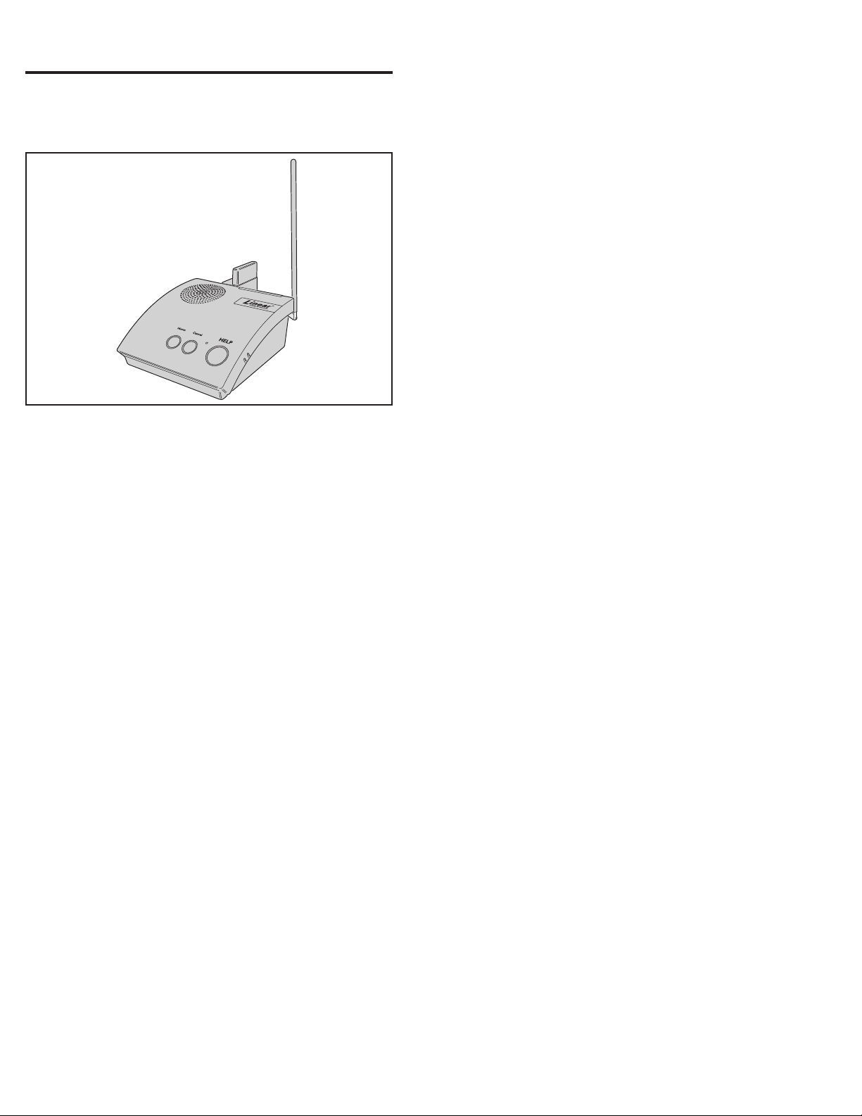
The PERS-4200 Console is a UL Listed supervised wireless emergency
reporting product designed for personal emergency reporting
applications. The table-top Console provides “pushbutton” emergency
assistance to anyone who desires additional security and peace of mind.
PERS-4200 Console
The Console receives signals from up to 16 Linear wireless transmitters
(called “sensors”). Activating a transmitter causes the Console’s digital
communicator to send the appropriate alarm report to the central
monitoring station via a standard land-line telephone connection or
through the optional cellular wireless communications module. In addition
to the Central Station report, voice prompts sound from the Console and
multi-color indicator rings around the Console’s buttons display status.
The emergency alarm can be triggered by the HELP button on the
Console or with a wireless transmitter. The fi re alarm can be triggered
by wireless smoke detectors, and gas alerts can be triggered by wireless
carbon monoxide detectors. Wireless transmitters can also be confi gured
as activity timer reset devices to verify activity at the subscriber’s location.
Voice Prompts
A built-in digital voice synthesizer can speak voice prompts in English, or
Spanish to guide the user during operation, and guide the installer during
programming.
✓ NOTE: Check the Linear Web site for Console fi rmware upgrades that
may support additional languages.
Language specifi c Console button labels are supplied for alternate
language use. For the visually impaired, a braille label is also supplied to
identify the Console’s buttons.
Power Supply
Powered by a low voltage plug-in power supply, the Console includes
a rechargeable backup battery for operation during AC power outages.
Programming
The Console must be confi gured before use. Linear’s RA4200 software
confi gures the Console remotely through the standard telephone line, or
locally through the Console’s USB port, or through the optional cellular
module via the Linear Voice Gateway. In addition, limited programming
can be done remotely through the standard telephone line with a
touch-tone telephone.
2
Page 5
2. Operation Summary
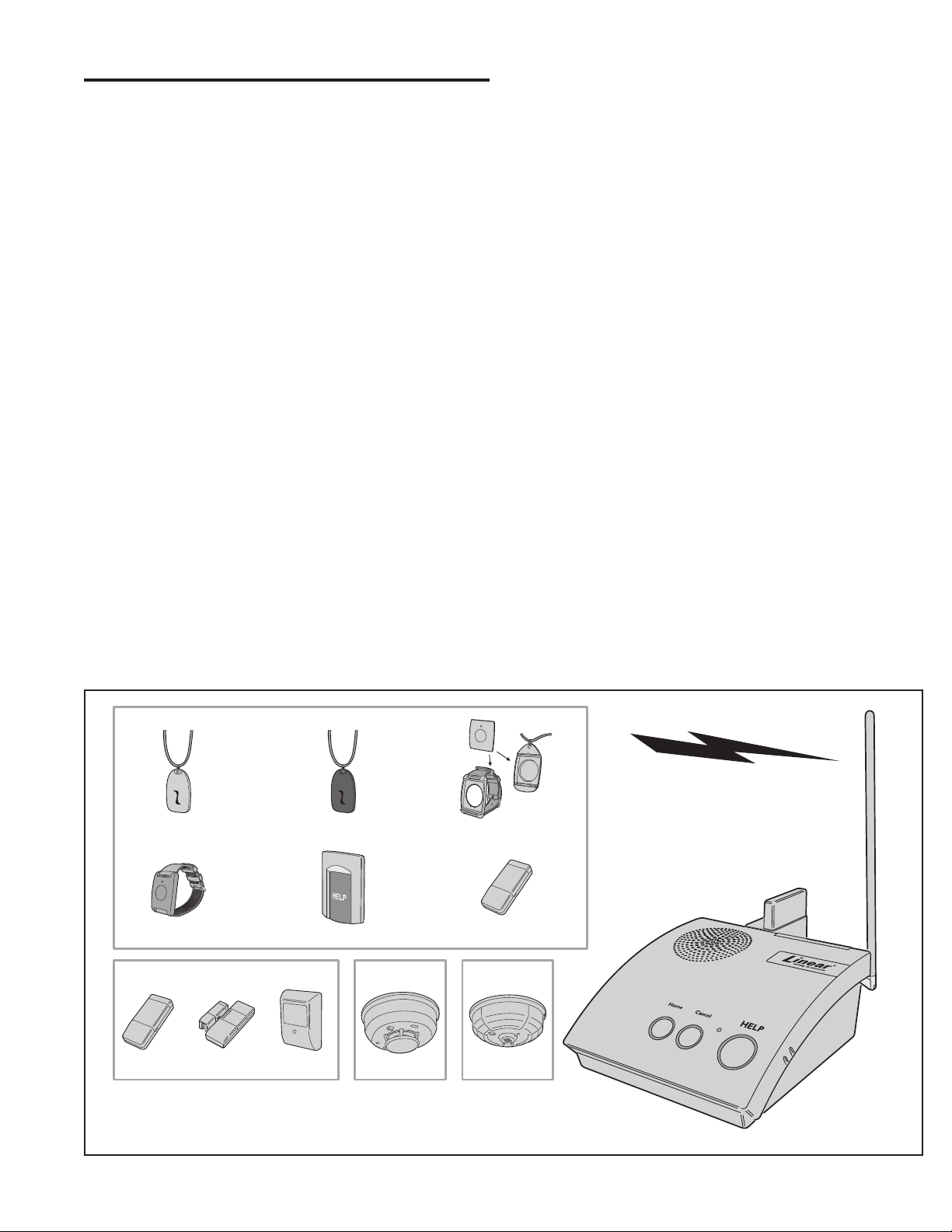
A variety of Linear’s DXS Format and DXT Format transmitters can be
used with the Console.
✓ NOTE: DXS Format transmitters are supervised, DXT Format transmitters
are not supervised.
Transmitters can be assigned to the following four functions:
Emergency
Portable, pendant, belt-clip, or wristband type transmitters and stationary
transmitters are used for personal emergency applications. When
an emergency transmitter is triggered, the Console announces the
emergency alarm and an emergency report is sent to the Central Station.
The emergency alarm can also be triggered by pressing the Console’s
HELP button.
Fire
The Model DXS-73 wireless photoelectric smoke alarm transmitter
triggers the fi re alarm. When the fi re alarm is activated, the Console
announces the fi re alarm and a fi re report is sent to the Central Station.
Carbon Monoxide (CO)
The Model DXS-80 wireless carbon monoxide detector triggers the
CO alarm. When a carbon monoxide alarm is activated, the Console
announces the gas alarm and a carbon monoxide report is sent to the
Central Station.
Activity
Switch or motion triggered transmitters (Models DXS-31/DXS-32 and
DXS-54) can be used for ensuring human activity. The DXS-54 motion
detector will monitor room activity. The DXS-31 and DXS-32 transmitters
can be wired to a pushbutton or switch for manual activity monitoring.
As long as a signal is received from each activity sensor during a
programmed activity time window, an alarm will not be triggered. 15
minutes before the programmed time expires, the HOME indicator will
start blinking and the Console will announce every three minutes that the
timer will run out soon. The activity timer can be reset with a signal from
one of the activity transmitters or by pressing the HOME button on the
Console. Failure to reset the activity timer within the programmed time
period will trigger the Console’s emergency alarm and send an inactivity
report to the Central Station.
2.1 Console Alarm Priorities
Alarm Priorities by Type
Each type of alarm is assigned a priority. Higher priority alarms override
lower priority alarms. Smoke alarms (on/off horn sound) have the highest
priority, followed by carbon monoxide alarms (on/off buzz sound),
emergency alarms (3 beeps sound), then other types of maintenance
and reminder reports (various sounds).
EMERGENCY TRANSMITTERS
DXS-LRP DXS-LRP-BK
DXS-LRW
ACTIVITY TRANSMITTERS
DXS-31
DXS-32
DXS-54
UP TO 16 TRANSMITTERS
TOTAL CAN BE USED WITH
EACH CONSOLE
DXS-LRC
DXS-65 DXS-31
SMOKE
DXS-73
CARBON
MONOXIDE
DXS-80
PERS-4200 Compatible Transmitters
PERS-4200
CONSOLE
3
Page 6
2.2 Console Options
Cellular Interface Module
The Model UMTS-3G Cellular Interface Module provides 2-way
over-the-air digital communications between the Console and the
monitoring service. The cellular module can be used to replace the
traditional land-line telephone connection for emergency reporting.
Remote Speaker/Microphone Module
The Model RSM-MODULE Remote Speaker/Microphone Module extends
the usable range for 2-way audio communications with the monitoring
service. The plug-in module and its remote speaker/microphone unit
allow the monitoring service to talk and listen to the subscriber from an
additional location in the installation that is remote from the Console.
Alternate Console Labels
For customizing the Console, an alternate set of button identifi cation
labels are provided. The labels describe the Console’s buttons in French,
or Spanish language, or in Braille characters. Apply the label required to
the Console, above the buttons.
HOME Button Cover
For installations where the activity timer will not be used, a snap-on
button cover is supplied to hide the HOME button.
✓ NOTE: The HOME button cover cannot be easily removed once the
cover is in place.
OPTION MODULES PLUG INTO CONSOLE
CELLULAR
TELEPHONE
MODULE
PERS-4200 Plug-in Option Modules
IF REQUIRED, APPLY BRAILLE,
FRENCH, OR SPANISH
LABEL TO CONSOLE
TO HIDE THE HOME BUTTON IF THE
ACTIVITY TIMER IS NOT GOING TO BE
USED, SNAP THE HOME BUTTON
COVER INTO THE CONSOLE
TIP: INSTALL THE BUTTON COVER
BY PRESSING THE SLOT EDGE IN
FIRST, THEN SNAP THE TOP EDGE
OF THE COVER DOWN
REMOTE
SPEAKER/MICROPHONE
MODULE
OPTION
MODULE
SPEAKER
HOME
BUTTON
CANCEL
BUTTON
BUTTON
TEMPERATURE
HELP
SENSOR
MICROPHONE
NOTE FOR UL APPLICATIONS:
SPEAKER VOLUME MUST BE
SET SO ANNOUNCEMENTS CAN
BE HEARD FROM ACROSS THE ROOM
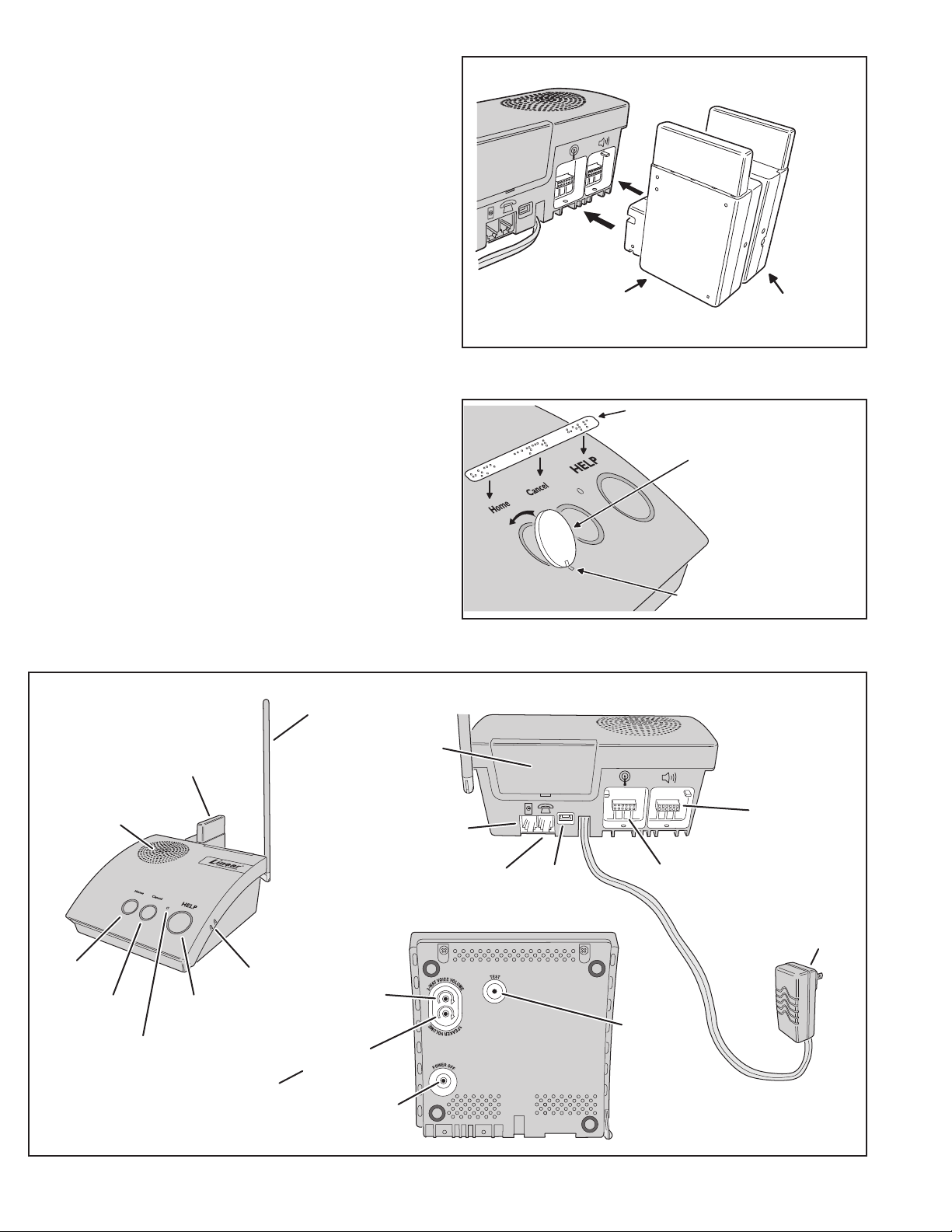
ANTENNA
BATTERY
DOOR
LINE IN
JACK
CONSOLE
FRONT
PHONE OUT
JACK
2-WAY
AUDIO
VOLUME
SPEAKER
VOLUME
POWER OFF
BUTTON
PERS-4200 Console Component Locations
NOTCH IN THE BUTTON COVER LINES UP
WITH NOTCH IN THE CONSOLE CASE
Alternate Console Labels and HOME Button Cover
CONSOLE
REAR
REMOTE
SPEAKER / MICROPHONE
MODULE SOCKET
USB
PROGRAMMING
CELLULAR TELEPHONE
MODULE SOCKET
JACK
TEST
BUTTON
CONSOLE
BOTTOM
POWER
SUPPLY
4
Page 7
3. Console Connections
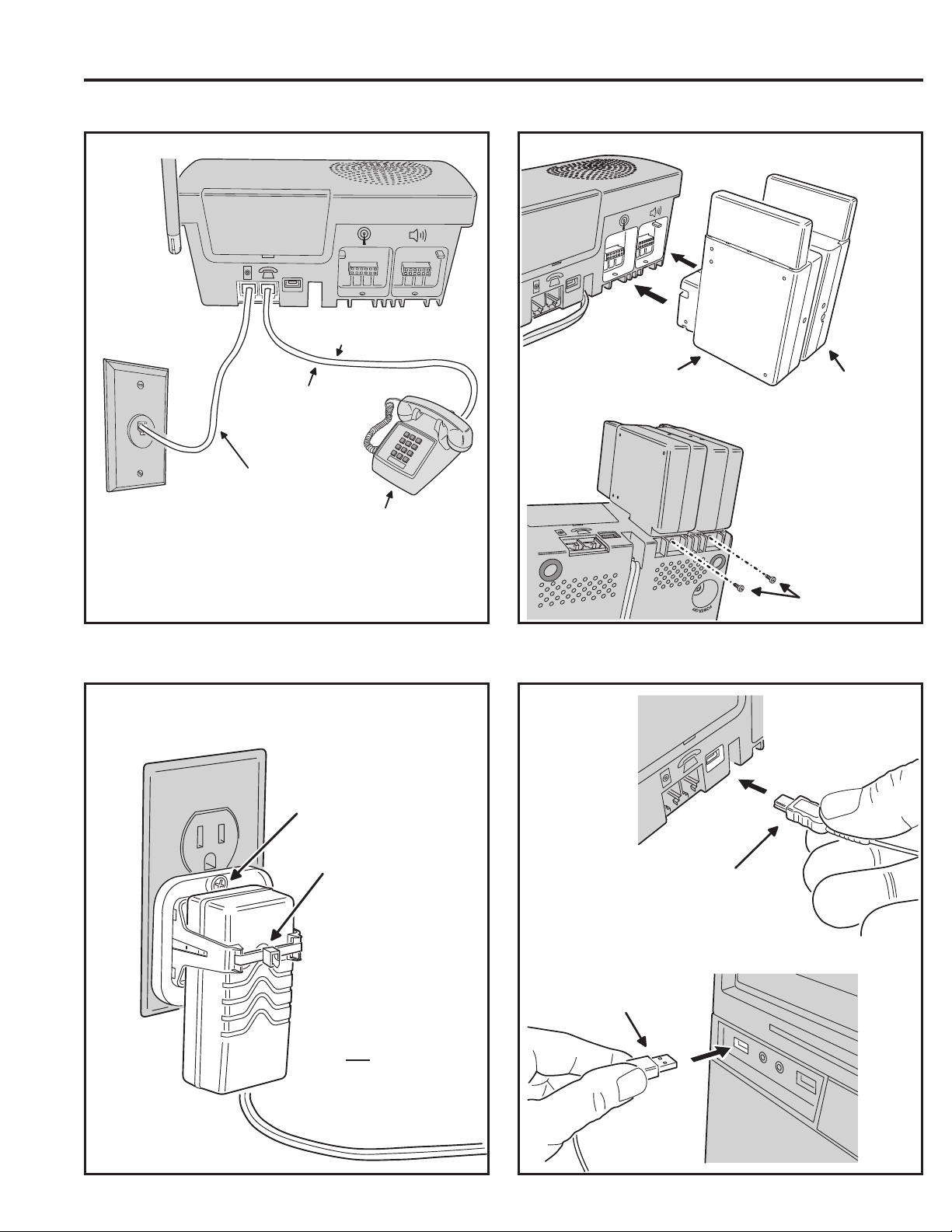
3.1 Telephone Connections 3.2 Option Module Installation
OPTION MODULES PLUG INTO CONSOLE
NOTE: THIS CONNECTION IS
OPTIONAL AND NOT REQUIRED
CELLULAR
TELEPHONE
CONNECT THE HOUSE
TELEPHONE TO THE
PHONE OUT JACK
CONNECT THE LINE IN JACK
TO THE TELEPHONE LINE
WALL JACK
OR ANY DEVICE CONNECTED TO
THE CONSOLE IS REPORTING TO
NOTE: THE LOCAL TELEPHONE
THE CONSOLE'S PHONE JACK
WILL BE DISCONNECTED FROM
THE TELEPHONE LINE WHILE
THE CENTRAL STATION
MODULE
REMOTE
SPEAKER/MICROPHONE
MODULE
CAUTION!
BE SURE CONSOLE POWER
IS OFF BEFORE CONNECTING
THE OPTION MODULES
BE SURE TO
SECURE MODULES
WITH SCREWS!
3.3 Power Supply Installation 3.4 Local Programming Connection
NOTE: FOR DECORA STYLE
OUTLETS, FLIP CLAMP OVER
ATTACH POWER SUPPLY
CLAMP TO OUTLET WITH
SCREW
SECURE POWER SUPPLY
TO CLAMP WITH A ZIP-TIE
CAUTION: BE SURE THE
OUTLET HAS 24-HOUR POWER
AND IS
NOT CONTROLLED BY
A WALL SWITCH
INSERT MINI-USB PLUG
INTO JACK ON REAR OF
THE PERS-4200 CONSOLE
INSERT USB PLUG
INTO PROGRAMMING
COMPUTER USB PORT
PROGRAMMING ONLY
FOR LOCAL
5
Page 8
4. Console Modes & Features
The Console operates in several modes and has features that support
both the provider and the subscriber.
4.1 Provider Modes
The Console has special modes of operation to aid the installer during
setup and confi guration.
Power Off Mode
Power Off Mode allows for out-of-service storage of the Console without
discharging the backup battery.
Not-Ready Mode
For a Console to report, an account number, Central Station telephone
number, and reporting format must be programmed. If these settings for
PSTN reporting or IP reporting are incomplete, the Console will indicate
Not-ready Mode.
Programming Mode
Programming Mode is used to setup and program the Console. It also
can be used to retrieve the unit’s event log data.
Test/Learn Mode
Test/Learn Mode is accessible using a recessed button on the bottom
of the Console. This mode can be used to locally learn, test, or erase
multiple transmitters. While in Test/Learn Mode, all normal operations of
the Console are suspended.
4.2 Provider Features
Several features of the Console are designed to aid and support the
system provider.
Event Log
The Console maintains a log of the 100 most recent system events. Each
event is tagged with the date and time the event occurred. The log can be
retrieved by the RA4200 software.
Upgradable Firmware
The PERS-4200 Console runs on internal software code called “fi r mware”.
The PERS-4200 Console uses two fi rmware resources, system fi rmware
and vocabulary fi rmware. Firmware code stays stored in the Console’s
memory and can be upgraded using the RA4200 application when
fi rmware updates become available.
The Device Firmware Upgrade utility (DfuSe) (included in the RA4200
application) can upgrade a Console and the optional UMTS-3G cellular module.
Multi-language Support
The Console supports two resident languages. The default languages
are English and Spanish.
To use an alternate language, the vocabulary fi rmware fi le must be downloaded
and installed in the Console’s memory with the RA4200 upgrade utility.
Volume Controls
Two volume controls are provided to customize the sound levels of the
Console for the installation.
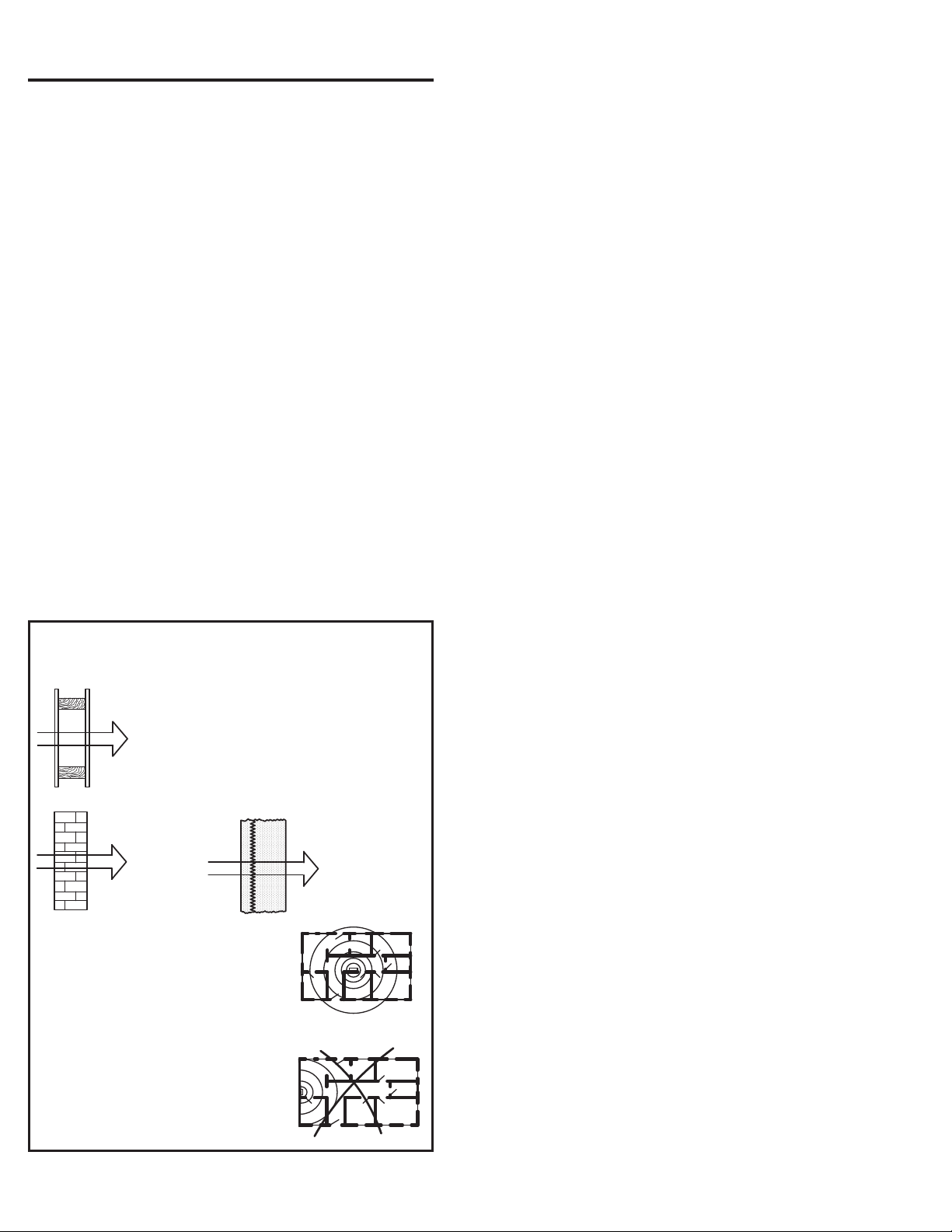
NOTE: THESE RF RANGE REDUCTIONS ARE ONLY RECOMMENDATIONS OF
POWER LOSS THROUGH THESE TYPES OF MATERIALS
WALLBOARD AND
WOOD STUDS
AFFECT RADIO RANGE
90% - 100%
OF FULL POWER
LIGHT CONCRETE
OR BRICK
65% - 95%
OF FULL POWER
CENTRALLY LOCATE CONSOLE
CONSOLE LOCATION WILL
AFFECT RADIO RANGE
TRANSMITTERS AT THE
OTHER END OF THE HOUSE
MIGHT BE TOO FAR AWAY
CONSTRUCTION
MATERIALS WILL
CONCRETE WITH STEEL
REINFORCEMENT OR
METAL LATH AND PLASTER
10% - 70%
OF FULL POWER
RIGHT
WRONG!
General Wireless Installation Tips
Auto Supervision
Any of the Console’s 16 sensor locations can be set to automatically
detect status supervision signals from transmitters. This feature makes
adding or replacing transmitters in fi eld units easier.
Variable Supervision Time
The Console can be set to delay reporting missing transmitter status
supervision signals until 12 or 24 hours, or 3, 7, 14, or 30 days. (Smoke
and CO detectors are always set at 24 hours per UL.)
Transmitter Low Battery Double-Check
The Console can be programmed to report a sensor low battery after
the fi rst or second time a low battery signal is received from the sensor.
Received Signal Strength (RSS) Test
To assist in setup and troubleshooting, when a transmitter is activated
while the Console is in Test Mode, the Console will measure and
announce the received signal strength (RSS) of the transmitter.
Remote Transmitter Enrolling
To make fi eld transmitter replacement easy, the transmitter’s ID code can
be remotely enrolled into the Console. The transmitter will be ready to
operate with the Console without having to “learn” the transmitter in.
Selectable Emergency Siren
The emergency siren can be programmed for audible or silent to support
different applications. (The smoke and CO siren are always active per
UL.)
Selectable Trouble Annunciation
The annunciation for Console and sensor low battery or supervisory
trouble can be audible or silent. (Trouble annunciation must be set to
audible per UL).
Selectable AC Power & Phone Line Fail Annunciation
The annunciation for AC power failure and telephone line failure can be
audible or silent. Audible annunciation can be set for only once, or once
every hour.
6
Page 9

4.3 User Modes
The Console features three modes of operation for the user. Each mode
changes the way the Console reacts or annunciates, depending on
where the user is, or what time it is.
Home Mode
Home Mode is the standard mode of operation for the Console when the
user is at home during the day. The Console will annunciate and report
all alarms as programmed.
The HOME button lights green when the Console is in Home Mode.
Away Mode
Away Mode is for when the user is going to be off site, away from the
Console. Portable emergency transmitter status reports are not monitored
while the Console is in Away Mode. Activity monitoring is suspended
during Away Mode. Console supervisory faults are always reported, but
not annunciated, in Away Mode.
Pressing the HOME button for fi ve seconds with switch the Console
between Home Mode and Away Mode.
Night Mode
Night Mode is an option that will suspend all Console supervisory
annunciations during a selected time period. This mode allows the user to
sleep without interruptions from the Console about most non-emergency
conditions. Activity monitoring and reminder messages can be used
during Night Mode, but are normally not scheduled during that time.
Console supervisory faults are always reported, but not annunciated, in
Night Mode.
During the programmed time for Night Mode, pressing the HOME button
for fi ve seconds with switch the Console between Night Mode and Away
Mode.
Emergency Reporting in any User Mode
In any of the three user modes, the Console is ready to report an
emergency. Emergency signals can be received from wireless sensors
or can be triggered from the Console’s HELP button. The alarms are
announced locally by type (emergency, fi re, or carbon monoxide alarm)
through the Console’s speaker and are reported to Central Station.
The Console will sound the alarm for fi ve minutes or until the report to
the Central Station is complete (Console emergency siren is optional
through programming).
As the alarm is being reported, the Console will announce:
0 “Emergency call being placed”
If the connection to the Central Station is unsuccessful, the Console will
repeat the announcement once during each 4-minute waiting period
between call sets. Once the alarm is reported or all retry sequences
have been exhausted, the Console will stop the annunciations and return
indicators to normal.
If 2-way audio is enabled, after the report is completed the Console will
announce:
0 “Emergency reported... Please stand by”
The Console will start the 2-way audio session (if enabled).
If 2-way audio is not enabled, after the report is completed the Console
will announce:
0 “Emergency reported”
4.4 User Features
Several features of the Console are designed to aid the system user.
Activity Timer
The activity timer is a feature that requires the subscriber to press a
button or activate a transmitter during one or two preset time windows to
prevent an inactivity alarm from being reported.
The HOME indicator will blink during the activity timer window. When
15 minutes remain on the activity timer the Console will announce to
the subscriber that the activity timer is running out. The subscriber must
press the HOME button or trigger an activity transmitter to respond to the
activity timer before it runs out, or an inactivity report will be sent.
Switching the Console’s mode between Home or Night Mode and Away
Mode will also reset the activity timer.
Smoke & CO Detection
For increased protection, wireless smoke and carbon monoxide detectors
can be programmed into the Console and report these conditions to
the Central Station. Smoke and CO sensors sound different Console
announcements and send unique reporting codes.
Reminder Messages
Five pre-recorded reminder messages and an alarm sound can be
programmed into the Console. The messages can be set to play once,
daily, weekly, or monthly, at a set times and dates. The Console can also
play a message to automatically remind the user to test the system.
Temperature Alarms
The Console contains a built-in sensor that constantly monitors the room
temperature. The system can report and annunciate if the current room
temperature measured is higher or lower than programmed temperature
limits. A temperature restore report is sent when the room temperature
returns between the high and low set points. As an option, temperature alerts
can be programmed to be only active while the Console is in Home Mode.
Speakerphone Mode
The Console can be programmed to act as a hands-free speakerphone
for incoming calls. If the user forgets to hang up, a timer will automatically
disconnect the call.
The speakerphone mode can only be used on incoming calls and will
not function when the Console is operating from backup battery power.
Attempting to answer while the Console is on backup power will
cause an emergency alarm.
✓ NOTE: If the Console communication is only through an IP connection
to the Central Station and it is not connected to a PSTN or MFVN
telephone line, this feature will not function
Remote User 2-Way Audio
Using a 4-digit password, the Console can be called from any telephone and
the caller can talk and listen to the user through the Console’s 2-way hands-free
speakerphone either in voice-activated mode or manual switching mode.
✓ NOTE: If the Console was confi gured with the “Answer Phone” option
NOT selected, this feature will not function.
✓ NOTE: If the Console communication is only through an IP connection
to the Central Station and it is not connected to a PSTN or MFVN
telephone line, this feature will not function.
Console Status Alert
The system continuously monitors the microprocessor that runs the Console’s
fi rmware code. If the microprocessor ever stops executing the fi rmware code,
the Console will indicate the trouble condition by sounding a steady tone from
the speaker. The tone will continue until the condition is corrected.
7
Page 10
5. Using the Provider Modes
The Console features special modes of operation to aid the installer
during setup and confi guration.
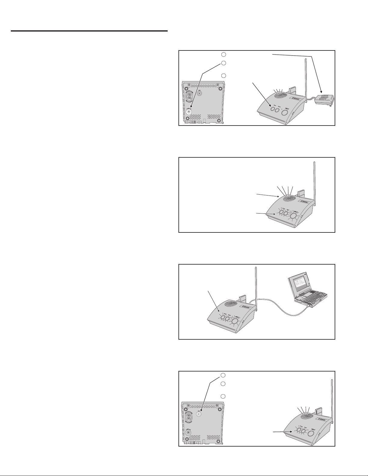
5.1 Power Off Mode
Power Off Mode allows for out-of-service storage of the Console without
discharging the backup battery. The Console is shipped from the factory
in this mode.
To place the Console in Power Off Mode from any other mode, remove
AC power, then press and hold the POWER OFF button on the bottom of
the Console for three seconds.
The next time AC power is applied, the Console will enter the programmed
operating mode.
UNPLUG THE POWER SUPPLY
1
PRESS THE POWER OFF BUTTON ON THE
2
CONSOLE BOTTOM FOR 3 SECONDS
THE CONSOLE WILL ANNOUNCE POWER OFF
3
AND THE INDICATORS WILL TURN OFF
"CONSOLE POWER OFF"
5.2 Not-Ready Mode
For a Console to report, an account number, Central Station telephone
number, and reporting format must be programmed. If any of these
settings are incomplete, the Console will indicate Not-ready Mode.
If the Console assumes Not-ready Mode when AC power is applied, a
1-second beep will sound (and annunciate, if programmed) and the three
indicators will blink green, orange, orange.
5.3 Programming Mode
Programming Mode is used to setup and program the Console. It also
can be used to retrieve the unit’s event log data.
Programming Mode can be accessed with RA4200 software on a PC
locally through a direct USB connection, remotely through a telephone
connection, remotely through cellular connection (if the optional
UMTS-3G cellular module in installed), or with limited access through a
telephone connection using just a touch-tone telephone.
✓ NOTE: During AC power loss, local and remote programming with
the RA4200 software is disabled unless the connection was already
established at the time of power loss.
When the Console is in Programming Mode, the three indicators will blink
green, orange, red.
Programming Mode will exit automatically after 3 minutes of inactivity, or
by pressing the CANCEL button.
While in Programming Mode, the Console is not operational and
cannot receive or report alarms.
5.4 Test/Learn Mode
Test/Learn Mode is accessible using the TEST button on the Console.
This mode can be used to locally learn, test, or erase transmitters.
To assist in setup and troubleshooting, when a transmitter is activated
while the Console is in Test Mode, the Console will measure and
announce the received signal strength (RSS) of the transmitter.
Enter Test/Learn Mode by pressing the recessed TEST button on the
bottom of the Console. Test/Learn Mode will exit automatically after
3 minutes of inactivity, or by pressing the CANCEL button.
When the Console is in Test Mode, the HOME and CANCEL indicators
will slowly blink green and orange.
While in Test/Learn Mode, the Console is not operational and cannot
receive or report alarms.
✓ NOTE: Transmitters can also be learned one at a time using the CANCEL
button (see Section 12.2).
Power Off Mode
IF THE CONSOLE DOES NOT HAVE AN
ACCOUNT NUMBER, CENTRAL STATION
TELEPHONE NUMBER (OR IP REPORTING
ADDRESS), OR REPORTING FORMAT
PROGRAMMED, THE CONSOLE WILL
INDICATE THAT IT IS NOT READY
CONSOLE WILL ANNOUNCE
WHEN POWERED ON
ALL THREE
INDICATORS
WILL BLINK
Not-Ready Mode
WHILE THE CONSOLE IS IN
PROGRAMMING MODE, ALL THREE
INDICATORS WILL BLINK
GREEN
ORANGE
RED
Programming Mode
PRESS AND RELEASE THE TEST BUTTON
1
THE CONSOLE WILL ANNOUNCE TEST MODE,
2
THEN THE FIRMWARE AND HARDWARE VERSIONS
ACTIVATE ALL SYSTEM SENSORS, THE CONSOLE
3
WILL ANNOUNCE SENSOR TYPE, ZONE, AND SIGNAL
STRENGTH
Test/Learn Mode
"CONSOLE NOT READY...
PLEASE CONFIGURE BEFORE USE"
GREEN
ORANGE
ORANGE
LOCAL
PROGRAMMING
CONNECTION
USB CABLE
NOTE: THE SAME INDICATIONS
OCCUR WHEN REMOTELY PROGRAMMING
"TEST MODE... FIRMWARE VERSION x.x...
HARDWARE VERSION x.x"
"EMERGENCY SENSOR... ZONE ONE...
FULL SIGNAL"
HOME & CANCEL
INDICATORS
WILL BLINK
GREEN
ORANGE
PROGRAMMING
PC
8
Page 11
6. Programming with RA4200
Linear’s RA4200 software confi gures the PERS-4200 Console remotely
or locally.
6.1 Software Description
The RA4200 software described in this manual supports the programming
Linear’s Model PERS-4200 Personal Emergency Reporting System. The
software runs on an IBM PC or compatible computer.
What is the RA4200 Remote Access Software?
The RA4200 Remote Access software is communications software that
programs all features of Linear PERS-4200 Consoles. It sets the options
for: Console alarm, audio, and sensors; communicator telephone numbers,
call routing, formats, reporting codes, account numbers, and reminder
messages and more. The RA4200 can also display the Console’s event log.
The RA4200 software has a help fi le that can be accessed at any time
by selecting “Contents” from the “Help” menu or by pressing the F1 key.
System Requirements
• IBM compatible personal computer with 2 GB RAM
• Windows XP, Windows Vista, or Windows 7 operating system
✓ NOTE: Windows 64-bit operating systems may require “Windows XP
Mode” download from Microsoft for “Panel Firmware Update (Dfuse)”
to run properly. See http://www.microsoft.com/windows/virtual-pc/
download.aspx
• VGA monitor
• For remote telephone connection, a ITU v.22bis standard 2400 baud Modem
• For local connection, an available computer USB 2.0 port and a Type A to
mini Type B USB cable.
• An Internet connection
• Hard disk drive with 50 MB available space for the software plus 18KB
available space for each account template fi le
How does RA4200 connect to a Console?
RA4200 can connect to the Console two ways:
• Remote connection over the telephone line using the computer’s modem.
• Local USB connection using a USB cable and the computer’s USB port.
Once the connection is made, the Console will check if its remote access
password matches the calling software’s password. If the passwords
match, access is granted.
Do I have to be connected to a Console to make programming changes?
Since Remote Access knows the Console’s programming structure,
you can modify an account template without being connected to a
Console. This means you can set all of the values for a specifi c Console
confi guration and then connect to a unit and send all of the values that
you have set. This is referred to as off-line Console confi guration.
How do I change Console settings while on-line?
While on-line with the Console, make any changes to the account
template then send the data to change the Console.
Can I make a template with the typical settings for all of my accounts?
Programming “templates” can be created to speed up programming
multiple Consoles. Common settings, such as the Central Station
telephone number, communicator format, Console and communicator
confi gurations which are shared by all of your accounts can be stored in
a generic account template. That template fi le can be used as a basis for
creating multiple customer account template fi les.
RA4200 Programming Software
9
Page 12

7. Programming Outline
Use the following programming outline to guide you through the steps
required to set up the RA4200 software and program a PERS-4200
Console. Many of the programming options available in the RA4200
program can be left in their default settings, and do not need to be
changed for most installations.
Setup RA4200 Software
• Install the software on your computer (Section 7).
• Test your computer’s modem (if used) (Section 8).
• Start the RA4200 program (Section 9).
Customize an Account Template
• Open a new or existing account template (Section 10).
• Enter customer information (Section 10.1).
• Set the Console’s password and operational options (Section 10.2).
• Enter any wireless sensor ID codes for sensors that won’t be learned locally
(Section 10.3).
• Select the Console’s communication method and options for PSTN and/or
IP reporting (Section 10.4).
• Choose the general communicator reporting options and assign any custom
reporting codes (Section 10.5).
• Set the Reminder Message schedules (Section 10.6).
Program the Console with the Account Template
• Connect to the Console (Section 11.2).
• Set the Console’s time and date (Section 11.3).
• Send the account template data to the Console (Section 11.3).
✲ IMPORTANT! AFTER ANY PROGRAMMING CHANGES ARE MADE TO
A CONSOLE, PERFORM THOROUGH TESTING TO VERIFY THAT THE
CONSOLE OPERATES AS INTENDED.
8. RA4200 Software Installation
The RA4200 remote access software is available on Linear’s web site at
this link:
www.linearcorp.com/downloads.php
The installation program will create a directory on your hard disk drive.
Be sure that you have at least 50 megabytes free on the hard disk for the
program and any account template fi les that you create.
To Install the Remote Access Program:
1. Download the RA4200 programming software installation package
from the Linear Web site at the link shown above.
2. Extract the RA4200Setup.ZIP fi le to expand the fi les.
3. Browse to fi nd the SETUP.EXE fi le. Double-click on SETUP.EXE and
the installation program will start.
4. Click the Next button to install the Remote Access software. Follow
the on-screen instructions as the setup program creates the directory
and copies the program fi les onto your hard disk. The setup program
will also install a virtual COM port driver to support a USB connection.
If desired, select the check box to place a RA4200 Remote Access
icon your desktop.
✓ NOTE: If RA4200 already is on your system and you are performing a
reinstallation, or an update, you will be prompted to modify, remove, or
repair the RA4200 software.
✓ NOTE: IF RA4200 IS INSTALLED ON WINDOWS VISTA OR WINDOWS 7,
RIGHT-CLICK ON THE DESKTOP ICON, SELECT PROPERTIES,
SELECT THE COMPATIBILITY TAB, CHECK “RUN THIS PROGRAM IN
COMPATIBILITY MODE”, AND SELECT WINDOWS XP.
To Remove the Remote Access Program:
1. Press START, SETTINGS, CONTROL PANEL. Double-click on ADD/
REMOVE PROGRAMS.
2. Select Linear RA4200 and click ADD/REMOVE or CHANGE/
REMOVE button depending on your Windows Operating system.
✓ NOTE: Alternately, you can select UNINSTALL from the Linear RA4200
folder on the start menu.
10
Page 13
9. Testing the Modem
A modem is used when connecting to a Console remotely, over the
telephone line. A modem is not required for local programming with a
USB cable.
When using a modem, be sure that the computer is running correctly
and that the modem is installed and working properly before you run the
RA4200 Remote Access Program.
Use the following steps to test the modem and determine the computer’s
COM port number that it is connected to.
To Test the Modem in Windows XP
Windows Control Panel can be used to test the modem and determine
what COM port the modem is connected to.
1. Press START, SETTINGS, CONTROL PANEL.
2. Double-click on PHONE AND MODEM OPTIONS.
3. Click on the MODEMS tab. The modem and the COM port used
should be shown.
4. Note the COM port number. It’s used when setting COM port in the
RA4200 Send/Receive window (see Section 11.1).
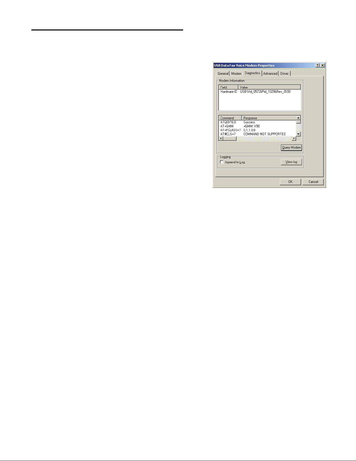
5. Click PROPERTIES and select the DIAGNOSTICS tab.
6. Click QUERY MODEM. If the modem is connected and working
properly, the Modem Information window will display detailed
Command and Response modem information. If the modem is not
working properly, Windows will notify you.
Windows XP Modem Test
11
Page 14
10. RA4200 Software Overview
The RA4200 software is a Windows compatible program with menus and
tabs to select various account fi elds to make selections and enter data.
10.1 Starting the Program
To Run the Program:
Double-click on the RA4200 desktop icon or press START, point to ALL
PROGRAMS, Linear, RA4200 and click on RA4200.
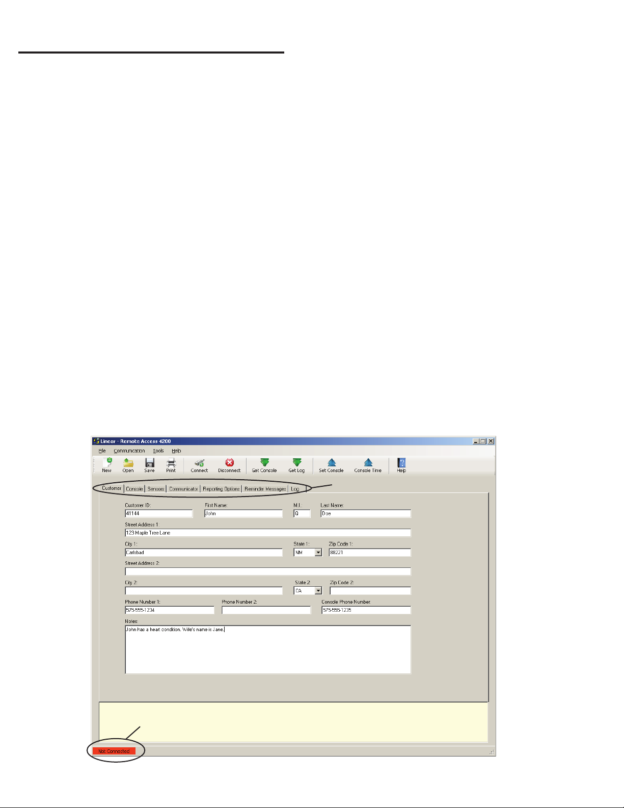
The RA4200 program will launch, displaying the menu bar and icons, the
Account Template with its seven tabs, a communications status window,
and a connection status indicator at the bottom.
10.2 The Account Template Tabs
Seven tabs are available for the Account Template. Each tab displays
major areas for programming and administrating a PERS-4200 Console
installation.
The Account Template tabs function as follows:
Customer
Displays fi ll-in fi elds for details of the subscriber’s information for
the specifi c PERS-4200 installation. Fields include name, address,
telephone numbers, customer ID#, and a large fi eld for special
notes regarding the subscriber.
Console
Displays fi ll-in fi elds for setting information and options for the
specifi c PERS-4200 Console. General settings such as passwords,
siren enable, voice prompts, voice language, temperature limits,
activity timer and Night Mode time windows can be set. Several
other Console options and settings are also available in this tab. The
Console’s time and date settings are displayed.
Sensors
Displays the 16 wireless sensor zones of the PERS-4200 Console.
Each sensor zone displays its sensor ID number, sensor type,
supervision option, two-way audio option, and the current sensor
battery and supervision status.
Communicator
Displays Console connection options for public switched telephone
network (PSTN) and internet protocol (IP) reporting. Typical PSTN
settings are for the communicator’s Central Station telephone
numbers, account number, reporting format, audible dialing tones,
and dialing format. Typical IP settings are for Central Station IP
address and port numbers, IP account number, IP reporting format,
voice gateway IP address and port numbers.
Reporting Options
Displays reporting options for the Console. Options for AC failure
reporting, supervisory event reporting, mode switch reporting,
automatic answer, automatic status report interval, speakerphone
timer, two-way audio mode, dialing delay, and 4x2 reporting codes.
Reminder Messages
Displays the eight subscriber Reminder Message slots and their
options. Also displays an option for setting the Reminder timeout
interval and audio replay option. Each Reminder Message can
be enabled, set for a type, and programmed to an activation
schedule. An automatic system test reminder message can also be
programmed.
Log
Displays the event log of the PERS-4200 Console. After the log is
retrieved from the Console, this tab will show the system events with
a time and date stamp in the order that they occurred.
CONNECTION STATUS
INDICATOR
ACCOUNT TEMPLATE TABS
COMMUNICATIONS
STATUS WINDOW
RA4200 Customer Tab
12
Page 15

10.3 The Menu Bar
The menu bar provides access to each of the programs sub-menus. The
icons below the menu bar are used to open, save, and print subscriber
Account Templates and perform various actions with the PERS-4200
Console.
Drop-down Menu Items and Icons
The sub-menus that can be accessed from the Menu Bar are:
File
NEW
Opens a blank Account Template. The common Console default values are
already fi lled in.
OPEN
Loads a saved Account Template into the RA4200 workspace. Only one
Account Template can be open at a time in the RA4200 workspace.
SAVE
Saves the open Account Template to the hard drive. A warning dialog will be
displayed if the template will overwrite the existing fi le.
PRINT / PREVIEW
Opens the account information print preview window to allow printing of
the active Account Template. Shows what will be printed on the screen with
options to zoom in or print the document. Resulting printout is the entire
content of the Account Template fi le and the Console’s event log in text
format.
EXIT
Closes the RA4200 program. If the Account Template has changed, you will
be asked if you want to save it.
Communication
CONNECT
Opens the Send/Receive window. Uses the telephone number and
password from the open template. Sets up and starts a modem or COM
port (local with USB) connection.
DISCONNECT
Terminates the connection between the RA4200 program and the
PERS-4200 Console.
GET CONSOLE
Retrieves the Account Template from the PERS-4200 Console that is
currently connected to the RA4200 program.
GET LOG
Retrieves the Event Log from the PERS-4200 Console that is currently
connected to the RA4200 program.
SET CONSOLE
Sends the Account Template from the RA4200 program to the PERS-4200
Console that is currently connected.
CONSOLE TIME
Opens the Set Time window. This function can be used to set the date and
time or get the date and time of the Console currently connected to the
program. Daylight saving time can be enabled or disabled, and the start and
end weeks of daylight saving time can be adjusted.
Tools
CLEAR EVENT LOG
Deletes the logged events from the connected PERS-4200 Console.
TEST IP REPORTING
Sends a test IP message from the Console to the central station. Requires
a modem or USB connection to the Console, and an Internet connection.
IMPORT OR EXPORT FILE VIEWER
For reading the content of an *.ra3 export fi le, or an *.ra5 import fi le.
EXPORT FILE TO VOICE GATEWAY
Creates an *.ra3 export fi le from the template that is currently open in the
RA4200 and send it to the Linear Voice Gateway (LVG) server. This feature
requires an internet connection. The LVG server supplies the fi le to Console
via the Console’s cellular module.
RETRIEVE IMPORT FILE FROM VOICE GATEWAY
Retrieves an *.ra5 import fi le from the Linear Voice Gateway (LVG) server.
This feature requires an internet connection. The LVG server supplies the
fi le to the PC for storage.
MERGE IMPORT (*.RA5 / *.RA6) or EXPORT (*.RA3) FILE
Merges data from an import fi le into the current open template in RA4200.
Open the appropriate template (*.ra1) fi rst before attempting a merge
function. Data from an import fi le will overwrite current input fi elds in the
opened template (be sure to save the template after merging). Merging
an export fi le with the current open template in RA4200 is also allowed
supported.
Toolbox
PANEL FIRMWARE UPDATE (DfuSe)
Opens the download tool which supports upgrading the system and
vocabulary fi rmware of a PERS-4200 Console and the fi rmware of the
UMTS-3G cellular module.
Help
CONTENTS
Opens the help Contents search window. Used for accessing the RA4200
program’s built-in help fi le. Function key F1 also accesses the help fi le.
ABOUT RA4200
Displays the version number of the RA4200 software.
13
Page 16

11. Creating a Custom Account Template
Each PERS-4200 Console installation requires an Account Template.
While many items are the same in different Consoles reporting to
the same Central Station, some items (account number, customer
information, & sensor information) are unique for each installation.
A custom Account Template is created by editing the default Account
Template included with the RA4200 software. The customized template
should then be saved with a unique name for the account and then sent
to the PERS-4200 Console.
11.1 Customer Tab
The customer tab displays fi ll-in fi elds for details of the subscriber’s
information for the specifi c PERS-4200 installation.
✓ NOTE: All fi elds are optional and do not have to be fi lled in. This
information is for PERS provider account reference and is not sent to
the Console.
Customer ID
Enter a unique identifi er in the CUSTOMER ID fi ll-in fi eld for the installation.
(The Customer ID is different from the communicator’s account number).
Account Template Management
Account templates that are created get stored on the programming PC
or onto a server or cloud storage. These account template fi les should
be named referencing the subscriber, customer ID number, or other
identifi cation that will make it easy to link each fi le with an installation.
Keep these fi les in a safe location. If a fi le is lost or deleted, it can be
recreated by retrieving the programmed information from an already
programmed Console, although the data on the Customer tab will be lost
and have to be reentered.
Customer Name
Enter the subscribers fi rst, middle, and last name in the three fi ll-in fi elds.
Customer Address 1 & 2
Enter the subscribers primary street, city, state, and zip code in the four
fi ll-in fi elds. Four additional fi ll-in fi elds are provided for a secondary
address.
Telephone Numbers
Three fi ll-in fi elds for telephone numbers are provided. Enter the Console
telephone number and up to two additional telephone numbers for the
subscriber.
Notes
Enter any special or additional information about the subscriber in the
NOTES fi ll-in fi eld.
CONNECTION STATUS
INDICATOR
ACCOUNT TEMPLATE TABS
COMMUNICATIONS
STATUS WINDOW
14
RA4200 Customer Tab
Page 17

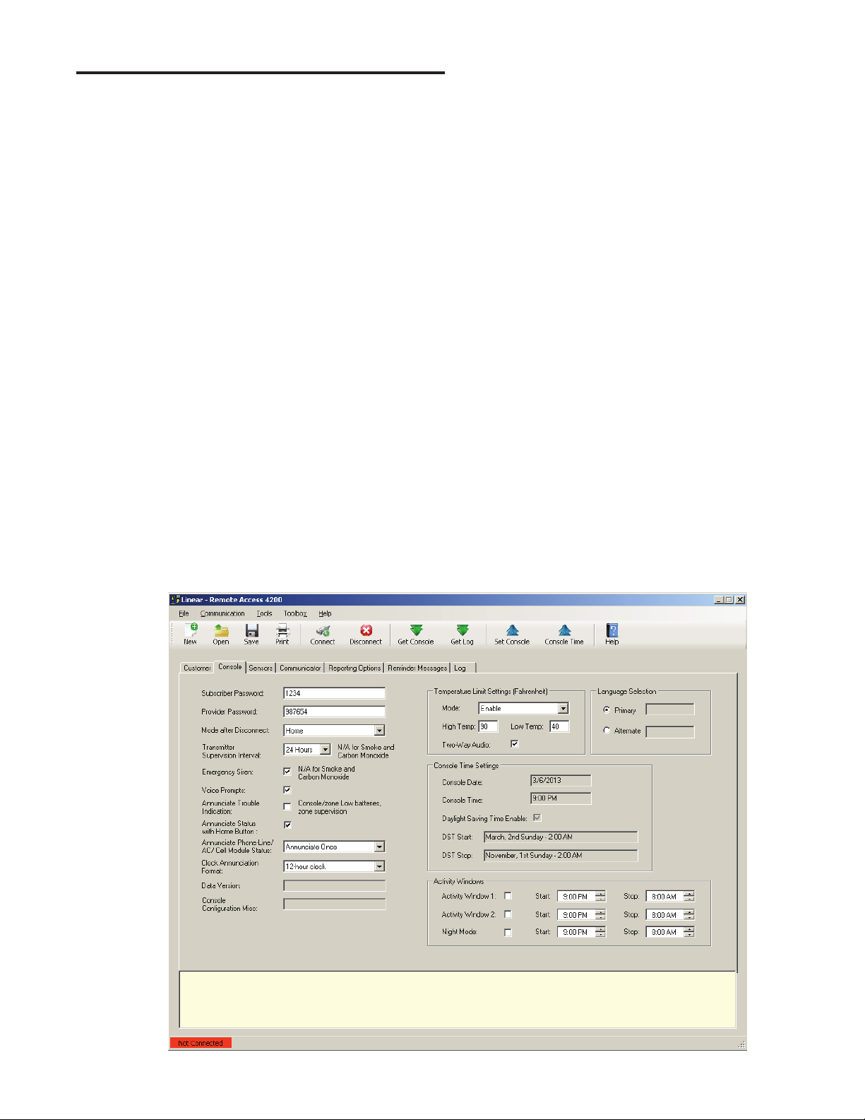
11.2 Console Tab
The Console tab displays fi ll-in fi elds for setting information and options
for the specifi c PERS-4200 Console.
Subscriber Password
Enter a new 4-digit subscriber password for the Console. This is the
password that the subscriber can use to call the Console from a remote
telephone and access user features. The factory default is 1-2-3-4.
Provider Password
Enter a new 6-digit provider password for the Console. This is the
password that allows the PERS provider to locally or remotely connect to
a Console and access programming. The factory default is 9-8-7-6-5-4.
Mode After Disconnect
Select the mode the Console will assume after programming when the
Console disconnects:
• Home — The Console will assume Home Mode after disconnect (default).
• Away — The Console will assume Away Mode after disconnect.
Transmission Supervision Interval
Supervised transmitters can send recurring status signals to the Console.
This option sets the length of time required before the Console will
recognize that a sensor’s status reports have not been received.
✓ NOTE: This setting does not affect supervision timing for smoke and
carbon monoxide detectors. These types of sensors are always set by
the Console to require reception of a status signal at least once every
24 hours.
Select one of the six options for the supervision interval: 12 hours, 24
hours (default), 3, 7, 14, or 30 days. This setting effects all non-smoke
and CO supervised sensors programmed into the Console that
have status supervision enabled.
✓ NOTE FOR UL APPLICATIONS: UL requires the Transmitter Supervision
Interval option to be set to 24 hours.
Emergency Siren
The Console contains an emergency siren that can sound for fi ve
minutes when an emergency alarm is triggered, or until the report to
the monitoring service is complete. The default for the siren is enabled.
Optionally the siren can be disabled by un-checking this option box.
✓ NOTE: This setting does not affect emergency alarms from smoke and
carbon monoxide detectors. These types of sensors always trigger the
emergency siren regardless of this setting.
Voice Prompts
The Console contains a voice synthesizer that can announce system
alarms and status. The default for the voice prompts is enabled. Optionally,
the voice prompts can be disabled by un-checking this option box.
RA4200 Console Tab
15
Page 18

Annunciate Trouble Indication
With this option box checked, the Console will announce three system
trouble conditions if they occur: Console low battery, sensor low battery,
and no sensor status. Sensor troubles type are announced followed by the
sensor zone number. The default is to not annunciate these conditions.
✓ NOTE FOR UL APPLICATIONS: UL requires the Annunciation Trouble
Indication option to be enabled (option box checked).
Annunciate Status with Home Button
A short press of the HOME button will cause the Console to announce
the Console’s time, current mode, and any trouble conditions. The default
for status annunciations is enabled. Optionally, status annunciations can
be disabled by un-checking this option box.
Annunciate Phone-Line/AC Status
If the telephone line is disconnected, or the AC power to the Console
fails, the Console can annunciate these conditions. These annunciations
will clear when the condition is corrected.
The default sets these types of annunciations to ANNUNCIATE ONCE.
Alternately, use the this option to select OFF or ANNUNCIATE EVERY
HOUR. Regardless of this setting, the Console records the condition in
the event log and can report AC power failure to the monitoring service
(if AC reporting is enabled).
✓ NOTE: To prevent disturbing the subscriber, these annunciations will be
suppressed while the Console is in Night Mode
Clock Annunciation Format
Both 12-hour (AM/PM) and 24-hour (“military”) time formats are supported
in time announcements for Console status and reminder messages.
The default sets the time annunciations to 12-HOUR CLOCK format.
Alternately, use the this option to select 24-HOUR CLOCK format.
Data version
Displays the version number of the Console’s data for factory use and
troubleshooting.
Console Confi guration Misc.
Displays confi guration numbers of the Console for factory use and
troubleshooting.
Temperature Limit Settings
The Console contains a built-in sensor that constantly monitors the room
temperature. The system can report and annunciate if the current room
temperature measured is higher or lower than programmed temperature
limits.
The Console will announce the high or low temperature alert every minute
until the room temperature is within the programmed acceptable limits.
The temperature limit alert is enabled by default. Select DISABLE to turn
off this feature or select ENABLE HOME MODE ONLY to sound and
report temperature alerts only while the Console is in Home Mode.
The default set-point for the low-temp alert is 40°F (4.4°C).
The default set-point for the high-temp alert is 90°F (32.2°C).
To change the temperature set-points, enter new values (in Fahrenheit)
into the HIGH TEMP and/or LOW TEMP fi ll-in fi elds.
A TWO-WAY AUDIO check box is available to select if a temperature
alert starts a 2-way audio session with the monitoring station. The check
box is selected by default. Alternately, un-check this box to inhibit 2-way
audio after a temperature alert.
Language Selection
The Console can annunciate voice prompts in English or Spanish to guide
the user during operation, and guide the installer during programming.
The two resident languages in the Console are English (EN) and
Spanish (ES). Choose the active language for the Console using the
radio buttons in the Language Selection area.
To use a different language, the language vocabulary fi le must
fi rst be downloaded and installed in the Console’s fi rmware (See
Section 15.2).
Console Time Settings
The Console contains a built-in clock and calendar, and supports
automatic daylight saving time adjustment. The Console’s current time
and date setting and the daylight saving information is displayed on the
Console tab or the RA4200 software.
To change these settings, use the CONSOLE TIME function on the
COMMUNICATION menu (or press the CONSOLE TIME icon on the
toolbar ribbon). See Section 11.3.
✓ NOTE: If the UMTS-3G cellular module is installed, the Console’s time
will be set automatically over the air by the network.
Activity Windows
The activity timer is a feature that requires the subscriber to press the
Console’s HOME button or activate a activity reset transmitter during one
or two preset time windows to prevent an inactivity alarm from being
reported.
Two activity time windows can be set. Each time window can be enabled
or disabled, and has a start and stop time.
• To enable Activity Window 1 and/or Activity Window 2, check the enable
box next to the start and stop times.
• Set the start time for the activity window.
• Set the stop time for the activity window.
Night Mode
Night Mode is an option that will suspend all Console supervisory and
reminder annunciations during the Night Mode time window. This mode
allows the user to sleep without interruptions from the Console about
non-emergency conditions.
• To enable the Night Mode time window, check the enable box next to the
start and stop times.
• Set the start time for Night Mode.
• Set the stop time for Night Mode.
16
Page 19

11.3 Sensors Tab
The Sensors tab displays fi ll-in fi elds for setting information regarding the
wireless sensors programmed into the Console. Sensor status indicators
also display the current condition of the sensor.
Up to 16 wireless sensors can be used with each PERS-4200 Console.
The transmitter’s ID number is printed on a removable tag attached to
the unit’s lanyard.
TRANSMITTER'S
ID NUMBER IS
PRINTED ON TAG
Low Battery Report Options
Supervised wireless sensors send low battery signals when they detect
that their battery is low. When a low battery signal is received from a
wireless sensor, two options are available to control when the Console
reports a low sensor battery.
• Option 1 - When a low battery signal is received from a sensor, the Console
will immediately report a low battery.
• Option 2 - When a low battery signal is received from a sensor, the Console
will wait for another low battery signal from the same sensor within a 24 hour
period before reporting a low battery.
✓ NOTE: In Night Mode, the low battery annunciations are suppressed, but
Console reporting is not.
Select Option 1 or Option 2 for the Console. This setting will affect all
wireless sensors used with the Console.
Transmitter ID Tag
SENSOR STATUS
RA4200 Sensors Tab
17
Page 20

Sensor Zones
Each of the Console’s 16 wireless sensor zones has individual setup
options. All the options are set on the Sensors tab.
ID
Each wireless transmitter is coded with a unique ID number at the
factory. If the transmitter has been locally “learned” by the Console,
the ID number will appear in the ID fi eld.
Alternately, transmitters can be enrolled remotely into the Console by
entering the transmitter’s ID number into the ID fi eld. This feature is
typically used when sending pre-enrolled replacement transmitters
to the subscriber. When the subscriber receives the transmitter, it
will be pre-programmed into the Console and ready for use.
Type
Each sensor zone can be set to one of four sensor types, or set as
Not Installed. When a wireless transmitter is locally “learned” by the
Console, the sensor type will be automatically recognized and set
by the Console. When a transmitter is enrolled remotely from the
Console, the sensor type must be set manually.
The sensor types selections available are:
• Not Installed - For sensor zones that are unused.
• Fire - For smoke detector sensors.
• Activity Reset - For sensors used to reset the Activity Timer.
• Emergency - For sensors used to trigger the emergency alarm.
• Carbon Monoxide - For CO detector sensors.
Supervised
Supervised transmitters send recurring status signals to the
Console. Any of the Console’s 16 sensor zone locations can be set
to automatically detect status supervision signals from transmitters.
This feature makes adding or replacing transmitters in fi eld units
easier.
• Select AUTO DETECT for a sensor zone to automatically detect if
a wireless transmitter is sending status signals. Once the Console
detects status signals from a transmitter, it will expect to regularly
receive those signals or the Console will report that the transmitter is
missing. The transmitter supervision interval required for the Console
to report missing status transmissions is programmed in the Console
tab.
• Select DISABLE to set a sensor zone as a non-supervised zone
which will not require status reports from a wireless transmitter.
Sensor Status Indicators
On the Sensors tab, each of the Console’s 16 wireless sensors display
the sensor’s operational status and if two-way audio is enabled for the
sensor’s zone.
Two-way Audio Status
A TWO-WAY AUDIO check box is provided to select if the sensor
will start a two-way audio session after an alarm is triggered. Check
this box to enable two-way audio for this sensor.
If two-way audio has been globally disabled on the Reporting
Options tab, the TWO-WAY AUDIO check box will be grayed out,
but still show if it’s checked or not.
Low Battery Status
If a wireless sensor sends a low battery signal to the Console, when
the Console’s data is read into the RA4200, the STATUS LOW
BATT check box will be checked for that sensor’s zone.
Supervision Status
If the Console fails to receive a status signal from a supervised
wireless transmitter before the programmed time for TRANSMITTER
SUPERVISION INTERVAL on the Console tab expires, the Console
will indicate trouble and blink the CANCEL indicator.
When the Console’s data is read into the RA4200, the STATUS
TROUBLE check box will be checked for that sensor’s zone.
18
Page 21

11.4 Communicator Tab
The Communicator tab displays fi ll-in fi elds for setting information
regarding the Console’s communication method and options for PSTN
and IP reporting.
Communicator Fallback
The Console’s communicator can report to the Central Station through
the Public Switched Telephone Network (PSTN) or through Cellular IP
reporting (if the UMTS-3G optional module installed).
✓ NOTE: The PERS-4200 can report to a Central Station over phone
service provided by a Managed Facilities-based Voice Network (MFVN)
carriers via the RJ11 phone jack, per NFPA 72 2010, section 3.3.141.
The communicator fallback option selects the reporting path the Console
will use. Option boxes are grayed out for the reporting path that is not
selected.
The default is for dial-up PSTN reporting only. Select the option that is
supported by the Central Station. Two options are available:
• PSTN reporting only
• Cellular IP reporting only
When the communicator fallback option is selected, the 2-way audio
setting will automatically adjust for the reporting method chosen (PSTN
or IP reporting).
PSTN Dialing Sequence
The Console will make multiple attempts to make a connection with the
Central Station. Each telephone number can be called up to 25 times.
The communicator performs this dialing sequence to make a connection:
1. Call the primary telephone number to attempt to make a connection.
If no handshake tone is detected from the Central Station, retry the
primary telephone number up to fi ve consecutive times.
2. Call the secondary telephone number (if a secondary telephone
number is used) to attempt to make a connection. If no handshake
tone is detected from the Central Station, retry the secondary
telephone number up to fi ve consecutive times.
3. Stop dialing and wait four minutes.
4. Repeat steps 1, 2, and 3 up to fi ve times.
After all dialing attempts, if a connection to the Central Station is not
made, the sequence repeats using the backup reporting path.
When all retries are exhausted, the report buffer and Console indications
are reset to normal; annunciations will cease and trouble memory and
latched zones will return to normal. New events will cause a new attempt
to contact the Central Station.
RA4200 Communicator Tab
19
Page 22

Public Switched Telephone Network (PSTN) Reporting
Settings for dial-up reporting using the telephone network are set in this area.
Account Number
The account number can be up to 10 digits long. The last four digits of
the account number will be used as the communicator’s account
number for 4x2 and CID format reports to the monitoring service.
✲ IMPORTANT! THE ACCOUNT NUMBER FIELD IS REQUIRED.
• SurGard System III - compatible SIA requires a 10-digit number
• PSTN/SIA requires a 6-digit number
• PSTN/CID and 4 by 2 requires a 4-digit number.
Enter the account number for the specifi c Console.
Reporting Format
Three Central Station PSTN reporting formats are available.
• Contact ID (CID)
• SIA
• 4 by 2
Contact ID is the default format. Select one of the other formats as
required by the Central Station.
Dialing Format
The default dialing format is DTMF tone dialing. If the telephone system
that the Console will be connected to does not support DTMF tone
dialing, select pulse dialing.
Dialing Tones Audible
By default dialing tones do not sound from the Console’s speaker. This
option is typically used for troubleshooting telephone issues.
Check this option box to have the Console speaker active during dialing.
Primary Telephone Number
The primary telephone number is the number that will be dialed fi rst
in the dialing sequence. The number can be up to 20 digits including
commas that each add a one second pause.
✲ IMPORTANT! THE PRIMARY TELEPHONE NUMBER FIELD IS REQUIRED.
Secondary Telephone Number
The secondary telephone number is the number that will be dialed
second in the dialing sequence if the primary number is unsuccessful.
The number can be up to 20 digits including commas that each add a
one second pause.
Split Reporting
The Console can report supervisory events to a supervisory telephone
number if split reporting is enabled. Split reporting is disabled by default.
When split reporting is enabled, reports for alarm events, reminder
message timeouts, activity window expirations, and 2-way audio calls are
made to the primary and secondary phone numbers.
Reports of home/away mode, Console trouble conditions, sensor trouble
conditions, and Automatic Status reports are made separately to the
supervisory phone number only.
Supervisory Telephone Number
The supervisory telephone number is the number that will be dialed to
report supervisory events if split reporting is enabled. The number can
be up to 20 digits including commas that each add a one second pause.
Internet Protocol (IP) Reporting
The PERS-4200 Console can be confi gured to communicate over-the-air
(OTA) using the optional add-on Model UMTS-3G Cellular Module. The
Module supports over-the-air data reporting for the PERS Console using 3G
and voice communications through the carrier’s cellular telephone network.
The settings for IP reporting using the cellular module are set in this area.
IP Account Number
The FIBRO IP reporting protocol allows up to 10 digits in the account
number. PERS truncates the left-most digits of the account number to fi t
the reporting format used. The cellular module adds left-most zeroes as
necessary for IP reporting. Enter the account number used for SurGard
IP reporting for the specifi c Console.
DNIS / Line #
DNIS is used by the Central station to help identify accounts. This allows
there to be multiple panels sending SIA/Contact ID events using account
1234 for example. The DNIS may be transmitted to the automation
software/printer to ID account 1234 as belonging to dealer X (DNIS
00001) and the other account 1234 as belong to dealer Y (DNIS of
00002). If it is not used it should be sent as all 0’s and it will not allow the
SIA/Contact ID account numbers to be extended.
FIBRO Heartbeat
Enter the time (in seconds) required by the Central Station receiver for
the FIBRO heartbeat. Default is 7200 seconds.
Linear Voice Gateway Management Timer
Enter the time (in minutes) for the periodic management connection
to the voice gateway, used for over-the-air confi guration update and
fi rmware download.
SIM ID
Displays the Subscriber Identity Module ID being used in the cellular module.
Central Station IP Address
The area is for entering the Central Station’s primary and secondary IP
address’, local port, and remote port numbers for the server that will be
receiving alarm reports from the Console. Enter the values required by
the server.
Voice Gateway
The area is for entering the Central Station’s voice gateway IP address
for the Linear Voice Gateway that will be handling voice-over-IP (VOIP)
communications from the Console during 2-way audio mode. Refer to the
Linear Voice Gateway instructions and settings for details.
IP Reporting Format
Three Central Station IP reporting formats are available.
• Surgard System III-compatible SIA
• Surgard System III-compatible CID18 Extended
• Surgard System III-compatible CID58 Extended
SURGARD SYSTEM III-COMPATIBLE CID18 EXTENDED
format. Select one of the other formats if required by the Central Station.
Cellular Network ID
Used to connect to a specifi c network. This specifi es the numeric
network identifi er, which is made from the Mobile Country Code (MCC)
and Mobile Network Code (MNC).
IP Service
The cellular service data network name string. For example: wap.cingular
or m2m.com.attz.
LEMI Ports
This area displays the name and fi rmware revision number of any option
modules connected to the Console.
is the default
20
Page 23

11.5 Reporting Options Tab
The Reporting Options tab displays fi ll-in fi elds for setting information
regarding the Consoles’ general communicator reporting options and
includes a 4 x 2 section for assigning custom 4 x 2 reporting codes if
desired.
Report AC Fail
The default REPORT AC FAIL setting enables AC power failure and
restore reports with a random delay of up to one hour. Alternately, the
Console can be set to report AC power status without the random delay,
or be disabled.
Three options are available for AC failure reporting.
• The DISABLE setting will inhibit AC failure reporting.
• The ENABLE setting will report when the Console has been without AC
power for fi ve minutes. A restore report will be sent fi ve minutes after AC
power is restored.
• The ENABLE (RANDOM DELAY UP TO 1 HOUR) settings functions the
same as the ENABLE setting, except that any reports will occur at a random
time up to one hour from the event. This option can reduce collisions of
Central Station traffi c caused by a wide-spread power outage.
When the AC power status changes, after the fi ve minute wait period, the
Console will announce:
0 “Console power failure”
— OR —
0 “Console power restored”
Report Supervisory Events
The default is to report supervisory events to the Central Station. The
events will be reported to the primary/secondary telephone number
unless split reporting is enabled, which would cause the reports to go to
the supervisory telephone number.
Un-check the REPORT SUPERVISORY EVENTS option box to disable
reporting supervisory events.
Mode Switch Reporting
The Console can report to the Central Station when the Console is
switched between Home Mode and Away Mode.
The default MODE SWITCH REPORTING setting does not report mode
changes to the Central Station. To report mode changes, check this
option box.
Answer Phone
The default enables ring detection on the telephone line connected to the
Console. This setting must be on to support the remote RA4200 telephone
programming, remote limited touch-tone telephone programming, and
Speakerphone Mode.
If these features are not required or used, ring detection can be disabled
by un-checking the ANSWER PHONE check box.
RA4200 Reporting Options Tab
21
Page 24

Automatic Status Reports
Automatic status reports of all pending supervisory conditions can be
sent to the Central Station at a daily, weekly or monthly schedule until the
supervisory condition is cleared or corrected. If split reporting is enabled,
the automatic status report will be sent to the supervisory number only.
The automatic status report consists of a periodic test report, followed
operating mode report (Home Mode and Away Mode only) and any
supervisory conditions. Supervisory conditions that are covered by the
automatic status report include AC fail, Console low battery, missed
sensor supervision, and sensor low battery for all sensors learned in to
the Console.
✓ NOTE: Supervisory events are reported by automatic status report
regardless of the global REPORT SUPERVISORY EVENTS setting on
the Reporting Options tab. Also, AC power loss events are reported
by automatic status report regardless of the global REPORT AC FAIL
setting on the Reporting Options tab.
The default MODE setting for automatic status reports is disabled. To
have the Console send automatic status reports, select one of the three
MODE options:
• Daily
• Weekly
• Monthly
✓ NOTE FOR UL APPLICATIONS: UL requires the Automatic Status Report
Mode option be set to DAILY.
For each option, set the time for the automatic test report to occur in the
TIME area.
The DAY area selects the day of week or day of month for the weekly and
monthly automatic status reports.
Extended Event Log
The Console’s event log always records system alarm (Group 1) events.
Additional events are categorized as Group 2 and Group 3 events.
The default adds GROUP 2 and GROUP 3 events to the Console’s log:
Group 2
• Console mode changes (off, home, away, night)
• Activity sensor activations
• Inactivity alarm window expiration
• Reminder message timeout expiration
Group 3
• Remote access (RA4200) sessions
• Console supervisory events (AC power, low battery, phone trouble)
• Sensor supervisory events (supervision, low battery)
Speaker Phone Timer
The Console can be programmed to act as a hands-free speakerphone
for incoming calls. If the user forgets to hang up, a timer will automatically
disconnect the call.
The default disables Speakerphone Mode. To use the speakerphone
option, select 15, 30, or 60 minutes for the speakerphone automatic
disconnect timer.
Refer to the PERS-4200 User’s Guide for remote call-in speakerphone
operation instructions.
Two-way Audio Mode
The Console supports 2-way audio communications with the subscriber
through the Console’s speaker and microphone.
The default sets all Console sensors to have 2-way audio enabled. 2-way
audio can be enabled or disabled for individual sensors using the check
boxes on the Sensors tab.
If 2-way audio activation is selected for an emergency sensor, after the
monitoring service operator acknowledges the communicators report,
the Console will stop its siren (if enabled) and switch to the selected
audio mode for 90 seconds if:
• Two-way audio mode is selected (listen-only, two-way manual, or two-way
auto) in the RA4200 Reporting Options menu
— AND —
• The zone where an alarm is being repor ted is enabled for two-way audio.
Temperature Alarms have a separate setting to enable 2-way audio for
those types of alarms.
All other alarms or events are controlled solely by the global 2-way audio
setting in the Reporting Options menu and will go into 2-way audio if that
option is enabled.
There are four choices for 2-way audio:
• Disable (Globally) — Console will not report as an audio account to the
Central Station. No audio monitoring will occur.
• Two-Way Auto (default setting for PSTN reporting) — The Console
automatically switches between listen and talk depending on which party is
talking. The operator can still switch from listen to talk manually by pressing
“1”, or switch from talk to listen by pressing “3” on a telephone connected
to the line (with increased volume). Pressing “8” returns to two-way auto.
Pressing “9” disconnects the call. Press any key but “9” to extend the time
90 seconds.
• Two-Way Manual (default setting for IP reporting) — The operator will be
able to hear sound from the Console and will be able to talk through the
Console’s speaker. The operator can switch from listen to talk by pressing
“1”, or switch from talk to listen by pressing “3” on a telephone connected to
the line. Pressing “9” disconnects the call (press any key but “9” to extend
the time 90 seconds).
• Listen Only — The operator will be able to hear sound from the Console’s
microphone, but will not be able to talk through the Console’s speaker.
Pressing “9” on a telephone connected to the line disconnects the call
(press any key but “9” to extend the time 90 seconds).
Dialing Delay
To help reduce false alarms reported to the Central Station, a delay of
15 seconds can be entered for PSTN or IP reporting. During this delay
time, the subscriber can press the CANCEL button to cancel the alarm
reporting to the Central Station. After the delay, once the call is initiated
and the receiver handshake tone is detected (with PSTN reporting), or
the IP packet is sent (with IP reporting), the report cannot be cancelled.
The default setting for dialing delay is OFF.
4 x 2 Alarm Codes
The 4 x 2 reporting format uses four digits for the account number and
two digits for the alarm code.
The Console defaults for 4 x 2 reporting assigns alarm codes 11-26 to
Console zones 1-16, trouble codes 41-56 to Console zones 1-16, and 16
other general alarm codes.
Any of the default 4 x 2 alarm codes can be modifi ed as necessary. Enter
the new 2-digit code in the 4 x 2 area.
22
Page 25

11.6 Reminder Messages Tab
The PERS-4200 Console has a real-time clock calendar (RTCC)
function that can be set to the correct time and date, and then accessed
to schedule events and actions by the Console, including a scheduled
reminder message feature. Five pre-recorded reminder messages are
provided for this function and are included as part of each installed
language library. There are nine programmable message time slots to
use to set the reminder message types and schedule times.
✲ IMPORTANT! THE CONSOLE’S TIME AND DATE MUST BE SET PRIOR
TO USING THE REMINDER MESSAGE FEATURE.
All reminder messages (including alarm and system test reminder) are
enabled only in Home Mode and Night Mode. They are disabled when in
Away Mode.
The PERS provider can schedule events for these reminder messages
as a one-time reminder, or as a recurring daily, weekly, or monthly event.
When the programmed event time is reached, the scheduled reminder
message is announced and if enabled, repeats once every three minutes
unless silenced by pressing the CANCEL button. When the CANCEL
button is pressed to silence the announcement, the Console will sound
a reminder chime.
A 15 or 30-minute timeout interval can be programmed as a setting for all
reminder messages. If the reminder is not acknowledged prior to expiration
of the timeout interval, a missed reminder event report can be sent to the
Central Station (if reporting of missed reminder messages is enabled).
If multiple reminder messages are scheduled at the same time or in the
same timeout interval, they will all be announced sequentially and at the
same three minute intervals, based on the fi rst message annunciated.
Pressing the CANCEL button cancels all of the reminder messages
within the same timeout interval.
Reminder Settings
The reminder settings globally affect all nine programmable reminder
message time slots.
Report Missed Reminder
The Console will provide voice prompts during the 15 or 30 minutes prior
to message reminder window expiring (set by programming).
Upon expiration of message reminder window the following will occur if
the REPORT MISSED REMINDER check box is checked.
1. The Console will activate and send an reminder message timeout
report to the Central Station. If the missed reminder is a system test
reminder, an automatic test report will be sent with status of the
system. 2-way audio will not be initiated.
2. Upon receipt and processing of the alarm transmission, a 2-way audio
session will begin (if enabled).
To enable missed reminder message reporting, check the REPORT
MISSED REMINDER check box.
Audio Replay During Timeout
The factory default will replay the reminder message every three minutes
until the message is acknowledged or times out.
To suppress replaying the reminder messages, un-check the AUDIO
REPLAY DURING TIMEOUT check box.
RA4200 Reminder Messages Tab
23
Page 26

Timeout Interval
A 15 or 30-minute timeout interval can be programmed as a setting for all
reminder messages. If the reminder message is not acknowledged prior
to expiration of the timeout interval, a missed reminder event report can
be sent to the Central Station if reporting of missed reminder messages
is enabled.
The factory default sets the reminder message timeout to 15 minutes.
Alternately, 30 minutes can be selected for the TIMEOUT INTERVAL.
Reminder Time Slot Settings
There are eight standard reminder message time slots that can be
programmed and one time slot for the system test reminder. Each time
slot has options that can be set.
Slot Enable
SLOT ENABLE check boxes are displayed for each of the nine reminder
message time slots. Checking a SLOT ENABLE check box will enable
the reminder message that is programmed in that time slot.
A reminder message that’s already programmed can be temporarily
disabled by un-checking this check box without loosing the reminder
message settings.
Send Report
SEND REPORT check boxes are displayed for each of the eight standard
reminder message time slots. Checking a SEND REPORT check box
for a reminder message time slot will cause the Console to report a
non-acknowledged reminder message to the Central Station.
✓ NOTE: For any time slot to report, the global setting for missed reminder
reports must be enabled in the Reminder Settings area.
Reminder Type
Four types of reminder messages are available:
• Medication reminder
• Ride reminder
• Appointment reminder
• Alarm
Select the desired type of reminder message for the time slot. When the
selection is made, the Schedule Type dialog box will display.
Schedule Type
Viewing or changing the reminder type or schedule type will display the
Schedule Type dialog box. This area is for selecting the dates and times
that a reminder message will sound.
A reminder message can be scheduled for ONE TIME, DAILY, WEEKLY,
or MONTHLY with the Schedule Type selection.
Once a schedule is set, it will be displayed in the SCHEDULE area.
One Time Reminder
24
Schedule
Daily Reminder
Schedule
Weekly Reminder
RA4200 Schedule Types
Schedule
Monthly Reminder
Schedule
Page 27

Test Reminder
A test reminder message is provided for prompting the subscriber to
perform a system test. They will be prompted to activate their emergency
transmitter or press the HELP button on the Console. Either activation
will send a test report to the Central Station.
✲ IMPORTANT: IF USING THE TEST REMINDER MESSAGE FEATURE,
TWO-WAY AUDIO SHOULD BE ENABLED SO THAT THE CENTRAL
STATION CAN ACKNOWLEDGE THE TEST WITH THE SUBSCRIBER.
When the programmed system test time occurs, a reminder chime
sounds and the Console announces:
0 “Attention... It is time to test your personal emergency
system... Please press your personal help button”
✓ NOTE: The test announcement will repeat every three minutes regardless
of the AUDIO REPLAY DURING TIMEOUT reminder message setting.
When the subscriber activates their emergency transmitter or presses
the HELP button, the Console will send a test report to the Central
Station, then start a two-way audio session. The Central Station operator
typically acknowledges the test report with the subscriber using two-way
audio, then disconnects.
If the subscriber does not activate a transmitter or press the HELP button
before the reminder timeout interval has been reached, an automatic test
report will be sent to the Central Station.
✓ NOTE: If the system test reminder times out and an automatic status
report is sent, a two-way audio session will NOT be started, even if
two-way audio is enabled.
Creating or Editing Reminder Messages
Use the following steps to setup a reminder message. Different options
will be displayed depending on the type of message.
1. Choose a reminder message type.
2. Select One Time, Daily, Weekly, or Monthly for the Schedule Type.
3. Select the date(s) and time(s) that the reminder message will sound.
4. For ride or appointment messages, select the time for the ride or
appointment to announce during the message.
5. Check the SLOT ENABLE check box to enable the reminder message
time slot. The schedule displayed for the time slot will be grayed until
it is enabled.
6. Check the SEND REPORT check box to have the Console send a
report if this reminder message is not acknowledged. (Global missed
reminder reports must be enabled also.)
WHEN A TEST REMINDER
MESSAGE OCCURS...
"ATTENTION... IT IS TIME TO TEST YOUR
PERSONAL EMERGENCY SYSTEM....
PLEASE PRESS YOUR PERSONAL HELP BUTTON"
THE CONSOLE
ANNOUNCES
THE SUBSCRIBER ACTIVATES
A PORTABLE TRANSMITTER
- OR -
THE SUBSCRIBER PRESSES
THE HELP BUTTON
Acknowledging a System Test Reminder Message
THE CONSOLE WILL SEND
A TEST MESSAGE TO
THE CENTRAL STATION
25
Page 28

12. Console Communication
The RA4200 software connects to the PERS-4200 Console using the
Send/Receive window. A Console must be connected to the RA4200
before any data can be sent to, or received from it.
12.1 Send/Receive Window
The Send/Receive window sets up and starts a modem (remote) or COM
port (local with USB) connection to a Console. Press the CONNECT
button to display the Send/Receive window.
Account
The Account area has two settings. The telephone number fi eld and the
password fi eld will be automatically fi lled in with the Console’s telephone
number from the open account template. The telephone number and
password fi elds can also be manually fi lled in.
Modem Connection
The area is used setting up and connecting with a computer modem over
the telephone line.
The SETUP CONNECTION button displays the general, diagnostic,
and advanced Windows modem properties screens. The Query Modem
button on the Diagnostics tab is a good way to test that the modem is
working properly.
The CALL button starts the modem calling sequence.
COM Port Connection
The COM Port Connection area has a selection for the COM port to
use for the USB connection to the Console and a button to start the
connection.
12.2 Connecting to a Console
Telephone Modem Remote Connection
Use the following steps to remotely connect to a powered Console using
a telephone modem:
1. Open the Account Template created for the specifi c subscriber and
Console installation. The Console’s telephone number and password
will be acquired from the template.
2. Press the CONNECT button to display the Send/Receive window.
3. Verify that the desired telephone modem is displayed for the connection.
4. Press CALL to start the calling sequence. The progress is displayed
in the RA4200 connection status area.
5. The modem will place a call to the Console, wait a few rings, then hang
up. This readies the Console to answer a call. The modem will call the
Console again, the Console will answer and negotiate a connection
with the modem. The RA4200 will send the password to the Console,
if the passwords match, remote access will be granted.
6. When the connection is made, the green CONNECTED indicator will
display at the bottom of the RA4200 window.
7. When fi nished, press DISCONNECT to disconnect with the Console.
The red NOT CONNECTED indicator will display at the bottom of the
RA4200 window.
✓ NOTE: If the telephone line that the Console is connected to has
automatic telephone answering equipment that answers the line in three
rings or less, the Console may not be able to be remotely accessed.
COM Port USB Local Connection
During local USB programming, the Console will remain functional. Use
the following steps to directly connect to a Console using a USB cable:
1. Apply power to the Console.
2. Connect the Console to the programming computer with a Type A to
mini Type B USB cable.
3. Press the CONNECT button to display the Send/Receive window.
4. In the COM port Connection area, select the COM port that the
Console is connected to. Look for the port labeled STMicroelectronics.
5. Press COM Port Connect to connect to the Console. The progress is
displayed in the RA4200 connection status area.
6. When the connection is made, the green CONNECTED indicator will
display at the bottom of the RA4200 window.
7. When fi nished, press DISCONNECT to disconnect with the Console.
The red NOT CONNECTED indicator will display at the bottom of the
RA4200 window.
26
RA4200 Send/Receive Window
INSERT USB PLUG
INTO PROGRAMMING
COMPUTER USB PORT
PROGRAMMING PC
PERS-4200 CONSOLE
INSERT MINI-USB PLUG
INTO JACK ON REAR OF
THE PERS-4200 CONSOLE
USB Programming Connection
FOR LOCAL
PROGRAMMING ONLY
Page 29

12.3 Sending and Receiving Console Data
Once the Console is connected to the RA4200 software, data can be
exchanged in either direction.
Console Time and Date
The Console’s clock and calendar will maintain the current time & date.
✲ IMPORTANT! THE CONSOLE’S TIME AND DATE MUST BE SET PRIOR TO
USE TO SUPPORT THE EVENT LOGGING AND REMINDER MESSAGE
FEATURES.
✓ NOTE: If the Console is using IP reporting, the Console’s data and time
are automatically set by the cellular network.
If the Console’s clock or calendar needs setting or changing, use these
steps.
1. Connect to the Console. The green CONNECTED indicator will
display at the bottom of the RA4200 window.
2. Press CONSOLE TIME. The SetTime window will display.
3. To check a Console’s clock and calendar, press GET TIME. The
current settings will be displayed in the SetTime window.
— OR —
4. Enter the new time and date. If daylight saving time is enabled, verify
the start and stop dates. Press SET TIME to update the Console’s
date and time.
5. Press DONE to close the SetTime window.
First Time Programming for New Consoles
When a Console is new or un-programmed it will announce:
0 “Console not ready... please confi gure before use”
The Console must be programmed with an account number, a Central
Station phone number and a corresponding PSTN or IP reporting format.
If one or more of these required parameters is missing the Console will
not operate.
Use the following steps when programming a new Console:
1. Open the Account Template created for the specifi c subscriber and
Console installation.
2. Connect to the Console. The green CONNECTED indicator will
display at the bottom of the RA4200 window.
3. Press CONSOLE TIME. The SetTime window will display. If not
correct, enter the correct time and date. If daylight saving time is
enabled, verify the start and stop dates. Press SET TIME to update
the Console’s date and time. Press DONE.
4. Press SET CONSOLE. The template will be sent to the Console.
5. Press DISCONNECT to disconnect from the Console. The red NOT
CONNECTED indicator will display at the bottom of the RA4200
window.
Existing Console Programming
Connecting to a Console with existing programming can be managed
two ways:
• Method 1: Make the changes to an Account Template off-line fi rst, before
connecting to the Console, then connect to the Console and send it the
template.
• Method 2: Open an Account Template, connect to the Console, then retrieve
the data from the Console into the template.
The fi rst method is preferred when all programming for a Console has
been made (and is being stored) by the RA4200 software. This method
will keep all the PERS provider’s Consoles synchronized with the RA4200
Account Template fi les.
The second method is useful if programming changes have been made
to a Console through remote touch-tone telephone programming.
Those changes can be retrieved into an Account Template, updating the
template. Be sure to save the template after updating it.
Use the following steps when programming an existing Console:
1. Open the Account Template created for the specifi c subscriber and
Console installation. (When using Method 1, make any changes
required.)
2. Connect to the Console. The green CONNECTED indicator will
display at the bottom of the RA4200 window.
3. Method 1 - Press SET CONSOLE. The template will be sent to the
Console.
— OR —
4. Method 2 - Press GET CONSOLE. The Console’s data will be sent to
the template. Press SAVE and select an Account Template fi le name.
✓ NOTE: The data in the open template will be overwritten with the data
from the Console.
5. Press DISCONNECT to disconnect from the Console. The red NOT
CONNECTED indicator will display at the bottom of the RA4200
window.
27
Page 30

12.4 Limited Remote Telephone Programming
Some basic confi guration areas of the PERS-4200 Console can be
programmed by a remote telephone phone call. The programming is limited
to Reporting Format, Primary Phone Number, Account Number settings.
✓ NOTE: If the telephone line that the Console is connected to has
automatic telephone answering equipment that answers the line in three
rings or less, the Console may not be able to be remotely accessed
In this remote programming mode, the Console remains fully functional
and will continue to annunciate and report alarms as they occur, except
for the few seconds when confi guration memory is being updated at the
conclusion of a RA4200 programming session. Prior to the confi guration
update, the Console will continue to use its previously stored settings
for normal operation. If the remote programming connection is the same
as the Console’s reporting connection, the Console will terminate the
remote access session to report an alarm.
This remote programming mode times out after four minutes of inactivity
or by pressing the CANCEL button on the Console.
Connecting with the Console
Use the following procedure to connect with a Console with a touch-tone telephone:
1. Dial the number of the telephone line that the Console is connected
to, allow it to ring three times, then hang up
2. Wait 10 to 30 seconds, then call the Console a second time.
3. When the Console answers, a tone will sound for 8 seconds.
4. When the tone ends, enter the PERS Provider Password (default
987654) followed by the key.
5. The Console will announce over the telephone:
0 “Main menu”
0 “Press one to review or change report format”
0 “Press two to review or change primary phone number”
0 “Press three to review or change account number”
0 “Press nine to hang up”
6. Select the number of the programming option.
7. Press key at any time to return to main menu.
Option 1 - Reporting Format
When is pressed, the Console will announce over the telephone:
0 “Report format is <reporting format>... press
pound to accept or press star to change”
Press the key to accept the current format and return to the Remote
Programming Main Menu, or press the key to return to select a
different report format.
When is pressed, the Console will announce over the telephone:
0 “Press one for contact id”
0 “Press two for SIA”
0 “Press three for four by two”
0 “Press nine to hang up”
0 “Press zero for main menu”
If selecting a new format, the Console will announce over the telephone:
0 “Report format is <reporting format>... press
pound to accept or press star to change”
Option 2 - Primary Telephone Number
When is pressed, the Console will announce over the telephone:
0 “Primary phone number is <primary phone number>...
press pound to accept or press star to change”
Press the key to accept the current telephone number and return to
the Remote Programming Main Menu, or press the key to enter a
different telephone number.
The primary telephone number can be up to 20 digits long, including
delay characters. If more than 20 digits are entered, only the fi rst 20 digits
will be accepted.
✓ NOTE: To place a delay at any location in the telephone number, press
key. A 1-second delay will be inserted for each press of the
the
key. When the primary phone number is annunciated for review, each
1-second delay will be identifi ed by the word “PAUSE.”
When is pressed, the Console will announce over the telephone:
0 “Enter primary phone number followed by pound”
Enter the new primary telephone number and press the key, the
Console will announce:
0 “Primary phone number is <primary phone number>...
press pound to accept or press star to change”
Press the key to accept the current change and return to the Remote
Programming Main Menu.
Option 3 - Account Number
When is pressed, the Console will announce over the telephone:
0 “Account number is <account number>... press
pound to accept or press star to change”
Press the key to accept the current account number and return to the
Remote Programming Main Menu, or press the key to enter a different
account number.
The account number can be up to 10 digits long. PSTN/SIA requires
a 6-digit number and PSTN/CID and 4x2 require a 4-digit number. The
Console will left-truncate or left-pad the account number with zeros as
required for the reporting format and interface.
When is pressed, the Console will announce over the telephone:
0 “Enter account number followed by pound”
Enter the new account number and press the key, the Console will
announce:
0 “Account number is <account number>... press
pound to accept or press star to change”
Press the key to accept the current change and return to the Remote
Programming Main Menu.
If more than 10 digits are entered, only the fi rst 10 digits will be accepted.
✓ NOTE: The default account number is none.
Press the key to accept the current format and return to the Remote
Programming Main Menu.
✓ NOTE: The default reporting format is Contact ID.
28
Page 31

13. Sensor Learn / Test Mode
Wireless transmitters are called “sensors” in the PERS vocabulary. In
Learn / Test Mode the Console can learn new sensors, test sensors, and
erase all sensors.
✓ NOTE: While in Learn / Test Mode, all normal operations of PERS-4200
Console are suspended. No alarms or reports are made in this mode.
To exit this mode, press and release the CANCEL button. The Console
will exit Learn / Test Mode automatically after three minutes of no activity
(including RF activity from a learned sensor, which will extend Learn / Test
Mode for an additional 3 minutes).
13.1 Learning Sensors
The Console can “learn” up to 16 sensors. Use the following steps to
locally learn sensors into the Console:
1. Press and release the TEST button (located recessed on the bottom
of the Console). The Console will announce:
0 “Test Mode, fi rmware version [number]...
hardware version [number]”.
2. Press and release the TEST button again. The Console will announce:
0 “Ready to learn sensor... Zone [number]”.
3. Activate the sensor to learn. The Console will announce:
0 “[Fire, Activity, Emergency, or Carbon Monoxide] sensor learned”.
4. The Console will announce the next available zone number:
0 “Ready to learn sensor... Zone [number]”.
To advance to the next available zone without learning a sensor, press
the TEST button. Zones already programmed with a sensor are skipped.
5. Repeat Step 3 for each additional sensor (up to 16 total). When all
zone locations are full, the Console will announce:
0 “Zones full”
After Zone 16 has been skipped or learned, if there are any available
zones remaining, the learn sequence will advance to the fi rst available
skipped zone and allow learning another sensor. The learn sequence
will cycle through any available/skipped zones until either all zones are
programmed, or Learn / Test Mode is exited.
✓ NOTE: To exit Learn / Test Mode at any time, press the CANCEL button.
TEST BUTTON
BOTTOM OF PERS-4200 CONSOLE
1. PRESS TEST BUTTON, CONSOLE WILL ANNOUNCE VERSION
2.
PRESS TEST BUTTON AGAIN
3. CONSOLE WILL ANNOUNCE READY TO LEARN AND ZONE NUMBER
4. ACTIVATE SENSOR
5.
CONSOLE WILL ANNOUNCE SENSOR LEARNED
6. REPEAT FOR ADDITIONAL SENSORS, OR PRESS CANCEL TO EXIT
Learning Multiple Sensors
29
Page 32

13.2 Learning a Single Sensor
Learn Sensor Mode may also be entered by pressing and holding the
CANCEL button for fi ve seconds. The Console will announce:
0 “Ready to learn sensor... Zone [number]”.
Activate the sensor to learn. The Console will announce:
0 “[Fire, Activity, Emergency, or Carbon Monoxide] sensor learned”.
The Console will exit Learn Sensor Mode after learning one sensor. To
exit without learning a sensor, press the CANCEL button.
13.3 Erasing All Sensors
To erase ALL sensors, press and hold TEST button for fi ve seconds. The
Console will announce:
0 “Zones reset”
All learned sensors are erased by this operation. The Console will then
go to normal operation and announce:
0 “Console ready”
✓ NOTE: Any pending alarms or events for an erased zone will be cleared.
13.4 Testing Sensors
Each sensor learned into the Console should be tested. When a sensor
is tested, the Console will announce the type of sensor, the zone number,
and the RF signal level.
✲ IMPORTANT! AFTER CONSOLE INSTALLATION, PORTABLE SENSORS
SHOULD BE TESTED IN VARIOUS PLACES ON-LOCATION TO
DETERMINE THE EFFECTIVE RADIO RANGE OF THE SYSTEM.
Use the following steps to test each system sensor.
1. Press and release the TEST button (located recessed on the bottom
of the Console). The Console will announce:
0 “Test Mode... fi rmware version [number]...
hardware version [number]”.
2. Activate each sensor to test. For each sensor, the Console will
announce:
0 “[Fire, Activity, Emergency, or Carbon Monoxide]
sensor... zone [number]... [full or low] signal”.
If the sensor tested has a low battery, the Console will announce:
0 “Sensor low battery... zone [number]”
3. When fi nished, press CANCEL to exit Test Mode (Test Mode will
automatically exit after three minutes of inactivity).
"EMERGENCY SENSOR.... ZONE ONE... FULL SIGNAL"
PRESS TEST BUTTON
TO ENTER TEST MODE
PERS-4200
CONSOLE
IN TEST MODE
BOTTOM OF
PERS-4200
CONSOLE
TEST ALL SENSORS
PROGRAMMED INTO
THE CONSOLE
IMPORTANT!
TEST SENSORS FROM VARIOUS
LOCATIONS IN THE INSTALLATION
TO VERIFY THE EFFECTIVE RADIO RANGE
Testing System Sensors
30
Page 33

14. Event Log
The Console will log system events in its memory they occur. The log can
be retrieved by the RA4200 software. Each event is tagged with the date
and time that the event was recorded. The log contains the most recent
100 Console events.
Three standard reporting groups are supported:
Group 1 logging always occurs; all events related to alarms are logged:
• Sensor alarms (emergency, fi re, CO)
• Temperature alarms
• HELP button alarms
• 2-way voice sessions
• Alarm reset/cancel
• Central Station reports, attempts, retries and failures
• All button presses
Group 2 logging is optional; when enabled, mode changes, activity
monitoring, and reminder message expiration events are logged:
• Console mode changes (off, home, away, night)
• Activity sensor activations
• Inactivity alarm window expiration
• Reminder message timeout expiration
Group 3 logging is optional; when enabled, supervisory trouble and
remote access events are logged:
• Remote access (RA4200) sessions
• Console supervisory events (AC power, low battery, phone trouble)
• Sensor supervisory events (supervision, low battery)
✓ NOTE: Extended event logging options for Group 2 and Group 3 events
are selectable on the REPORTING OPTIONS tab.
14.1 Retrieving the Event Log
Use the following steps to retrieve a Console’s event log:
1. Connect to the Console with the RA4200 application.
2. Press the GET LOG icon (also available under COMMUNICATIONS
on the menu bar).
3. After the log is retrieved, it will be displayed on the LOG tab. Use the
scroll bar to view the entire log. The most recent event is indicated in
the log.
4. Disconnect from the Console.
14.2 Printing the Event Log
The contents of the log can be printed with the account summary using
the RA4200 PRINT / PREVIEW command.
14.3 Clearing the Event Log
In case the Console is going to be moved, re-confi gured, or used in a
different installation, the event log can be cleared from the Console’s
memory. To clear the log:
1. Connect to the Console with the RA4200 application.
2. Select CLEAR EVENT LOG from the RA4200 TOOLS menu.
3. Disconnect from the Console.
RA4200 Console Event Log
31
Page 34

15. Printing or Exporting a Template
For hardcopy records, an account template can be sent to a local printer
connected to the PC running the RA4200 Remote Access software.
The PRINT / PREVIEW tool also allows exporting an account template to
an Excel .XLS fi le or an Adobe .PDF fi le.
Use the following steps to print out or export an account template:
1. Open an account template in the RA4200 software. (Only one
template can be open at a time.)
2. From the FILE menu select PRINT / PREVIEW or on the toolbar, click
the PRINT icon.
3. The Account Information print preview window will be displayed. The
preview shows the account template contents detailed on separate
pages. The page that’s currently displayed and the zoom level can be
selected using the page navigation icons in the window.
4. To print the account template,7 select the printer icon. The Windows
print dialog box will appear, select any options, then click PRINT.
5. To export the account template, select the disc icon and choose Excel
or Acrobat (PDF) fi le. Choose the fi le destination and click SAVE.
PRINT BUTTON
EXPORT BUTTON
Print Preview Window
32
Page 35

16. Updating Console Firmware
The PERS-4200 Console runs on internal software code called
“fi rmware”. Firmware code stays stored in the Console’s memory and
can be upgraded using the RA4200 application when fi rmware updates
become available.
The PERS-4200 Console uses two fi rmware resources, system fi rmware
and vocabulary fi rmware. The UMTS-3G cellular module also has device
fi rmware. There is a Device Firmware Upgrade utility (DfuSe) included in
the RA4200 application.
When new fi rmware is released, it will be available on Linear’s Web site
on the software download page at:
www.linearcorp.com/downloads.php
16.1 System Firmware Update Utility Instructions
Use these steps to upgrade a Console’s system fi rmware:
1. Download the system fi rmware from Linear’s Web site and store the
fi le(s) in a location on the programming PC.
2. Place the PERS-4200 in Power Off Mode by removing AC Power
from the Console, and then press and hold the POWER OFF button
until the Console announces: “Console power off”, then release the
POWER OFF button.
3. Place the PERS-4200 into DfuSe mode by pressing and holding the
POWER OFF button while applying AC Power. The HOME, CANCEL,
and HELP indicators will blink.
✲ IMPORTANT: Once the Console is in DfuSe mode, do not power off the
Console during a fi rmware upgrade.
4. Open the RA4200 application and BEFORE connecting the USB
cable to the Console, from the RA4200 TOOLS menu, select Panel
Firmware Update (DfuSe).
5. Connect the Console to the programming PC with a USB cable. If
the Console is in DfuSe mode and properly connected to the USB
port, the device ‘STM Device in FDU Mode’ should display in the
“Available DFU and compatible HID Devices” area.
6. Click CHOOSE... and select the system fi rmware fi le to download
from the location it was saved on the PC. After selecting, “File
correctly loaded.” should appear at the bottom of the DfuSe window.
7. In the “Select Target(s):” area select Target Id “00 Internal
Flash”
8. When all settings are correct, click UPGRADE.
9. A DfuSeDemo pop-up dialog will always appear with a device warning.
Ignore this warning and click YES.
10. The status bar will indicate the status of the upgrade. First phase will
be erase, then download, then verify.
11. Click LEAVE DFU MODE. The RA4200 will disconnect the Console
and the Console will reset.
12. Click QUIT to exit the DfuSe utility.
13. Confi gure the Console with the RA4200 as required.
✓ NOTE: Should any problems happen during the upgrade phase (i.e.
wrong fi le selected and downloaded into a Console), this procedure can
be repeated to retry the upgrade again.
16.2 Firmware Update Utility Instructions
Use these steps to upgrade a Console’s vocabulary fi rmware or the
UMTS-3G cellular module’s fi rmware:
1. Download the fi rmware from Linear’s Web site and store the fi le(s) in
a location on the programming PC.
2. Place the PERS-4200 in Power Off Mode by removing AC Power
from the Console, and then press and hold the POWER OFF button
until the Console announces: “Console power off”, then release the
POWER OFF button.
3. Place the PERS-4200 into DfuSe mode by pressing and holding the
POWER OFF button while applying AC Power. The HOME, CANCEL,
and HELP indicators will blink.
✲ IMPORTANT: Once the Console is in DfuSe mode, do not power off the
Console during a fi rmware upgrade.
4. Open the RA4200 application and BEFORE connecting the USB
cable to the Console, from the RA4200 TOOLS menu, select Panel
Firmware Update (DfuSe).
5. Connect the Console to the programming PC with a USB cable. If
the Console is in DfuSe mode and properly connected to the USB
port, the device ‘STM Device in FDU Mode’ should display in the
“Available DFU and compatible HID Devices” area.
6. Click CHOOSE... and select the vocabulary fi rmware fi le or cellular
module fi rmware fi le to download from the location it was saved on
the PC. After selecting, “File correctly loaded.” should appear at the
bottom of the DfuSe window.
7. Check the “Verify after download” check box. In the “Select
Target(s):” area select Target Id “02 SPI Flash”
8. When all settings are correct, click UPGRADE.
9. A DfuSeDemo pop-up dialog will always appear with a device warning.
Ignore this warning and click YES.
10. The status bar will indicate the status of the upgrade. First phase will
be erase, then download, then verify.
11. Click LEAVE DFU MODE. The RA4200 will disconnect the Console
and the Console will reset.
12. Click QUIT to exit the DfuSe utility.
13. Confi gure the Console with the RA4200 as required.
✓ NOTE: Should any problems happen during the upgrade phase (i.e.
wrong fi le selected and downloaded into a Console), this procedure can
be repeated to retry the upgrade again.
33
Page 36

DfuSe Utility Connected to Console
Firmware File Selection
DfuSe Device Warning
34
Verify and Target ID Selection
Upgrading in Process
Upgrade Complete
Page 37

17. Appendix A - Reporting Codes
EVENT
DESCRIPTION
Group Partition (Ext)
CONSOLE EMERGENCY ALARM 1100 00 69 QA
ALARM CANCEL (ABORT) 1406 00 70 AB
CONSOLE LOW BATTERY 1302 00 73 YT
CONSOLE BATTERY RESTORE 3302 00 71 YR
CONSOLE SUPERVISORY (RECEIVER BOARD TROUBLE) 1381 00 40 MS
CONSOLE SUPERVISORY RESTORE 3381 00 40 MJ
LOSS OF AC POWER 1301 00 72 AT
AC POWER RESTORE 3301 00 94 AR
HOME MODE (ACTIVITY MONITOR ON)
AWAY MODE (ACTIVITY MONITOR OFF)
INACTIVITY ALARM (NO ACTIVITY) 1102 00 90 NA
AUTOMATIC STATUS (AUTOMATIC TEST) 602 00 93 RP
AUTOMATIC STATUS (TEST OFF NORMAL) 608 00 95 RY
REMINDER MESSAGE TIME OUT
HIGH TEMP ALARM (HEAT) 1158 00 74 KA
HIGH TEMP RESTORE 3158 00 75 KR
LOW TEMP ALARM (FREEZE) 1159 00 76 ZA
LOW TEMP RESTORE 3159 00 77 ZR
FIRE (SMOKE) ALARM 1111 XX
FIRE (SMOKE) LOW BATTERY
[1]
FIRE (SMOKE) SUPERVISORY 1200 XX
FIRE (SMOKE) SUPERVISORY RESTORE 3200 XX
CO ALARM (GAS) 1162 XX
CO LOW BATTERY 1384 XX
CO SUPERVISORY 1381 XX
CO SUPERVISORY RESTORE 3200 XX
EMERGENCY ALARM (PERSONAL/MEDICAL) 1101 XX
EMERGENCY LOW BATTERY 1384 XX
EMERGENCY SUPERVISORY 1381 XX
EMERGENCY SUPERVISORY RESTORE 3381 XX
TWO WAY AUDIO REQUEST 606 00 N/A
[1]
[1]
[1]
1372 00 91 UR
1371 00 92 UB
1356 00 96 MI
1384 XX
CID
4 X 2 SIA
[2]
[2]
[2]
[2]
[2]
[2]
[2]
[2]
[2]
[2]
[2]
[2]
10 + SENSOR # FA
40 + SENSOR # FT
40 + SENSOR # FS
40 + SENSOR # FQ
10 + SENSOR # GA
40 + SENSOR # GT
40 + SENSOR # GS
40 + SENSOR # GQ
10 + SENSOR # MA
40 + SENSOR # MT
40 + SENSOR # MS
40 + SENSOR # MJ
[3]
L90
REPORTING CODE
Reporting Code Notes:
• 1
Optional report depending on programming.
• 2
The CID Group/Partition # (Ext) code is the zone number that the alarm
or event is reported against. Console and non-zone-specifi c alarms/events
are reported using CID group/partition #00
• 3
The 4x2 format does not have a two-way audio request code. The call
must be established manually.
35
Page 38

18. Appendix B - Mode Table
HOME MODE
CONSOLE OPERATING MODE
AWAY MODE
(Overrides Night Mode)
NIGHT MODE
SYSTEM EVENT
Fire & CO Alarms
Fire & CO Supervisory
[2]
Timeout
Fire & CO Sensor Low
[2]
Battery
Console (HELP button) Alarm
Emergency Sensor Alarm
Emergency Sensor
Supervisory Timeout
Emergency Sensor Low
[2]
Battery
Console Trouble
Communication Status
(telephone/cell)
Module Status
Activity Monitor
Temperature Alarms
Missed Reminder Messages
Entering Mode
[2]
[2] & [5]
Reports to Central Station
✓ Ye s ✓ Ye s ~ If Enabled
✓ Ye s ~ If Enabled
✓ Ye s ~ If Enabled
Voice Announcement
[8]
[8]
Starts 2-Way Audio
N/A
N/A
Reports to Central Station
[6]
✓ Ye s ✓ Ye s ~ If Enabled
Voice Announcement
✓ Ye s ✗ No
✓ Ye s ✗ No
N/A
N/A
Starts 2-Way Audio
Reports to Central Station
[6]
✓ Ye s ✓ Ye s ~ If Enabled
Voice Announcement
✓ Ye s ✗ No
✓ Ye s ✗ No
✓ Ye s ✓ Ye s ~ If Enabled ✓ Ye s ✓ Ye s ~ If Enabled ✓ Ye s ✓ Ye s ~ If Enabled
✓ Ye s ✓ Ye s ~ If Enabled
~ If Enabled ~ If Enabled
✓ Ye s ~ If Enabled
✓ Ye s
~ If Enabled
[8]
[8]
[8] & [9]
✗ No ✓ Ye s
N/A
✓ Ye s
✓ Ye s ✓ Ye s ~ If Enabled
~ If Enabled
[11]
✓ Yes
✓ Ye s
[4]
~ If Enabled
From Away
Mode Only
[4]
~ If Enabled
✓ Ye s ~ If Enabled ✗ No ✗ No ✗ No ✓ Yes
[10]
[6]
✓ Ye s ✓ Ye s ~ If Enabled
N/A
N/A
N/A
N/A
N/A N/A
N/A
✗ No
✓ Ye s ✗ No
✓ Ye s ✗ No
✗ No ✓ Ye s
[7]
✗ No ✗ No ✗ No ✓ Ye s ✓ Ye s ~ If Enabled
[4]
~ If Enabled
✓ Ye s ✓ Ye s
[1]
[3]
~ If Enabled
✗ No
✗ No
[1]
[1]
[3]
~ If Enabled
[6]
✓ Ye s ✓ Ye s ~ If Enabled
N/A
N/A
N/A
N/A
N/A N/A
N/A
~ If Enabled ✗ No ✗ No
✓ Ye s ✗ No
✓ Ye s ✗ No
✗ No ✗ No
[3]
~ If Enabled
From Away
Mode Only
[3]
[11]
✗ No
~ If Enabled
[3]
~ If Enabled
✓ Ye s ~ If Enabled
From Away
Mode Only
Starts 2-Way Audio
[6]
N/A
N/A
[6]
N/A
N/A
N/A
N/A
[7]
[3]
N/A
Mode Table Notes:
• [1] Setting the Console in Away Mode clears all supervisory events for
emergency sensors only. Supervisory timers for Smoke detectors, CO
detectors, and activity monitor sensors are not affected; switching to Home
or Away Mode constitutes activity.
• [2] Supervisory events are reported by automatic status reports regardless
of the global REPORT SUPERVISORY EVENTS setting. Also, AC power
loss events are reported by automatic status reports regardless of the global
REPORT AC FAIL setting. Both settings are on the Reporting Options tab.
• [3] If ENABLE HOME MODE ONLY is selected for TEMPERATURE LIMIT
SETTINGS on the Console tab, temperature alarms will not occur in this
mode. Select ENABLE to allow temperature alarms in this mode.
• [4] Either ENABLE or ENABLE HOME MODE ONLY needs to be selected
on the Console tab for TEMPERATURE LIMIT SETTINGS to allow
temperature alarms.
• [5] Console supervisory faults are always reported, but not annunciated in
Away Mode and Night Mode.
• [6] To start a two-way audio session after a report is triggered by an
emergency alarm sensor, two-way audio must be globally enabled in
TWO-WAY AUDIO MODE on the Reporting Options tab and enabled for
the sensor’s zone with the TWO-WAY AUDIO check box on the Sensors tab.
36
• [7] For activity sensors, two-way audio is enabled globally in TWO-WAY
AUDIO MODE on the Reporting Options tab regardless of the activity
sensor’s zone setting with the TWO-WAY AUDIO check box on the Sensors
tab.
• [8] To enable Console/sensor zone low batter y and sensor zone super vision
annunciations, ANNUNCIATE TROUBLE INDICATION must be selected
on the Console tab.
• [9] To announce telephone line and AC power status, ANNUNCIATE
PHONE-LINE/AC STATUS must be selected on the Console tab.
• [10] The Console will only announce Home Mode when manually switched
from Away Mode using the HOME button.
• [11] To report missed reminder messages, the global REPORT MISSED
REMINDER option must be selected on the Reminder Messages tab and
the reminder message slot must have the SEND REPORT option selected.
Page 39

19. Appendix C - Communications Status Window Table
Below are possible messages that may appear
in the communications status window when
RA4200 is connected to a PERS-4200 Console.
Opening Port COM30
Initializing Com Port
Sending password
Login Success
Get status data
Console Type:
Standard Console
Protocol Ver: 5
Hardware Ver: 0
Firmware Ver: 2.4.0
Data Version (zone-panel-reminder-log-time-IPMiscConfi g1): -1-3-1-3-1-2-2
Console (PSTN) Account Number: 007152
Console AC: Good
Console Battery: Good
Console Mode: Home
Sensor Low Battery:
Sensor Supervision Trouble:
Done Get Status
‘CONNECT’ (no EXP. MODULES):
Opening Port COM30
Initializing Com Port
Sending password
Login Success
Get status data
Console Type: Standard Console
Protocol Ver: 5
Hardware Ver: 0
Firmware Ver: 2.4.0
Data Version (zone-panel-reminder-log-time-IPMiscConfi g1): -1-3-1-3-1-2-2
Console (PSTN) Account Number: 007152
Console AC: Good
Console Battery: Good
Console Mode: Home
Sensor Low Battery:
Sensor Supervision Trouble:
Done Get Status
‘GET CONSOLE’:
Get time data
Get zone data
Get console data
Get reminder data
Get IP confi guration
Cellular Signal Strength (dBm): 0
Get IP status data
Cellular Status:
Cellular Network:
Cellular Roaming:
Get status data
Console Type: Standard Console
Protocol Ver: 5
Hardware Ver: 0
Firmware Ver: 2.4.0
Data Version (zone-panel-reminder-log-time-IPMiscConfi g1): -1-3-1-3-1-2-2
Console (PSTN) Account Number: 007152
Console AC: Good
Console Battery: Good
Console Mode: Home
Sensor Low Battery:
Sensor Supervision Trouble:
Get Misc Confi g 1
Done Get Console
‘GET CONSOLE’ (CELL MODULE PRESENT):
Opening Port COM30
Initializing Com Port
Sending password
Login Success
Get status data
Console Type: Standard Console
Protocol Ver: 5
Hardware Ver: 0
Firmware Ver: 2.4.0
Data Version (zone-panel-reminder-log-time-IPMiscConfi g1): -1-3-1-3-1-2-2
Console (PSTN) Account Number: 007152
Console AC: Good
Console Battery: Low
Console Mode: Home
Sensor Low Battery:
Sensor Supervision Trouble: -1-2
Done Get Status
Get time data
Get zone data
Get console data
Get reminder data
Get IP confi guration
Cellular Signal Strength (dBm): -91
Get IP status data
Cellular Status: ---
Cellular Network: AT&T
Cellular Roaming: ---
Get status data
Console Type: xxxxxx Console
Protocol Ver: 5
Hardware Ver: 0
Firmware Ver: 2.4.0
Data Version (zone-panel-reminder-log-time-IPMiscConfi g1): -1-3-1-3-1-2-2
Console (PSTN) Account Number: 007152
Console AC: Good
Console Battery: Low
Console Mode: Home
Sensor Low Battery:
Sensor Supervision Trouble: -1-2
Get Misc Confi g 1
Done Get Console
‘SET CONSOLE’:
Set zone data
Set console data
Set IP Confi guration
Set reminder data
Set Misc Confi g 1
Done Set Console
‘GET LOG’:
Get log data
‘SAVE’:
Saving C:\Linear\RA4200\Accounts\Account1.ra1
‘DISCONNECT’:
Terminate call
Hanging up / Closing session
Terminating... Please wait a few seconds.
Wait Done.
‘OPEN’:
Opening C:\Linear\RA4200\Accounts\Account1.ra1
Tools->Clear Event Log:
Done Clearing Log
Tools->Test IP Reporting
Test IP reporting request sent
Tools-> File functions (when operation is cancelled):
SSH fi le transfer cancelled.
Tools -> Export fi le to Voice Gateway
SSH fi le transfer error.
or
SSH export fi le transfer success.
Tools -> Retrieve Import fi le from Voice Gateway
SSH fi le transfer error.
or
SSH import fi le transfer success.
Tools->Merge Import
No merging error.
or
Merging errors encountered.
37
Page 40

20. Specifi cations
CODING FORMATS
DX CODE 24-BIT A1D PPM 1,048,567 Codes
DXS CODE 24-BIT A1D PPM 1,048,567 Codes
POWER REQUIREMENTS
PRIMARY SUPPLY Plug-in Switching Power Supply
Input: 120 VAC 60 Hz
Output: 14 VDC 1.7 Amps Maximum
BACKUP SUPPLY 7.2 Volt 2 Amp/Hour Ni-Mh Battery
BACKUP OPERATION DURATION 24 Hours Minimum
BATTERY LIFE EXPECTED 3 Years
RF CHARACTERISTICS
RECEIVER TYPE Dual-diversity Superheterodyne
RF SENSITIVITY -105 dBm Typical
RADIO FREQUENCY 315 Mhz
MAXIMUM RANGE 1000 Feet Line-of-sight (Tested with DXS-LRC transmitter)
COMMUNICATOR
DIAL-UP COMMUNICATOR FORMATS 4 x 2,
ADEMCO Contact ID
SIA
UL Tested with SURGARD
SGMLRG-DG
Central Station ReceiverCentral Station Receiver
PSTN DIALING Tone or Pulse
DIALING / IP REPORTING DELAY 0 or 15 Seconds
IP REPORTING FORMATS Surgard System III-compatible SIA
Surgard System III-compatible CID18 Extended
Surgard System III-compatible CID58 Extended
REMOTE PROGRAMMING PASSWORD 6 Digits
REMOTE COMMUNICATIONS PASSWORD 4 Digits
ACCOUNT NUMBER LENGTH SurGard FIBRO IP (SIA) 10-digits
PSTN/SIA 6-digits
PSTN/CID and 4 by 2 4-digits.
PRIMARY TELEPHONE NUMBER 20 Digits
SECONDARY TELEPHONE NUMBER 20 Digits
SUPERVISORY TELEPHONE NUMBER 20 Digits
CONSOLE STATUS REPORT Optional 1, 7 or 30 Day Report
IP ADDRESSING IPv4 Addressing Only
CONSOLE
OPERATING TEMPERATURE 32°-120° F (0-49° C)
ACTIVITY TIMER PERIOD Two Programmable Time Windows
PSTN REPORTING AUDIO Listen-only, 2-way Manual, 2-way Voice Activated (duplex) Speakerphone
IP REPORTING AUDIO Listen-only or 2-way Manual
SIZE 6.25” W x 2.85” H x 6.25” D (9.6” H with antenna up)
REGULATORY
CONSOLE Designed to conform to:
UL 1635 Digital Alar m Communicator
UL 1637, Home Healthcare Signaling Device
Smoke Signaling Accessory File S2499 / UL217
National Fire Protection Association (NFPA 72)
ROHS
POWER SUPPLY CSA, ETL, FCC, Effi ciency Level 4
EMISSIONS FCC Part 15 & Part 68, Industry Canada
38
Page 41

21. Regulatory Information
This device complies with Industry Canada and Part 15 of the FCC Rules.
Operation is subject to the following two conditions: (1) This device may
not cause harmful interference, and (2) This device must accept any
interference received, including interference that may cause undesired
operation.
This equipment has been tested and found to comply with the limits for
Class B Digital Device, pursuant to Part 15 of the FCC Rules. These
limits are designed to provide reasonable protection against harmful
interference in a residential installation. This equipment generates and
can radiate radio frequency energy and, if not installed and used in
accordance with the instructions, may cause harmful interference to radio
communications. However, there is no guarantee that interference will not
occur in a particular installation. If this equipment does cause harmful
interference to radio or television reception, which can be determined by
turning the equipment off and on, the user is encouraged to try to correct
the interference by one or more of the following measures.
• Reorient or relocate the receiving antenna
• Increase the separation between the equipment and receiver
• Connect the equipment into an outlet on a circuit different from that to which
the receiver is connected
• Consult the dealer or an experienced radio/TV technician for help
Any changes or modifi cations not expressly approved by the party
responsible for compliance could void the user’s authority to operate the
equipment.
• Les changements ou modifi cations non approuvés expressément par la
partie responsable de la conformité pourrait annuler l’autorité de l’utilisateur
à faire fonctionner l’équipement
This device complies with Industry Canada licence-exempt RSS
standard(s). Operation is subject to the following two conditions: (1) this
device may not cause interference, and (2) this device must accept any
interference, including interference that may cause undesired operation
of the device.
• Le présent appareil est conforme aux CNR d’Industrie Canada applicables
aux appareils radio exempts de licence. L’exploitation est autorisée aux deux
conditions suivantes : (1) l’appareil ne doit pas produire de brouillage, et (2)
l’utilisateur de l’appareil doit accepter tout brouillage radioélectrique subi,
même si le brouillage est susceptible d’en compromettre le fonctionnement.
The antenna used for the transmitter must be installed to provide a
separation distance of at least 7.87 inches (20 cm) from all persons, and
must not be co-located or operating in conjunction with any other antenna
or transmitter other than those supplied with the PERS-4200 console.
• L’antenne de l’émetteur doit être installé à une distance d’au moins 7,87
pouces (20 cm) de toutes les personnes, et ne doit pas être placé ou utilisé
en conjonction avec toute autre antenne ou tout autre émetteur autres que
ceux fournis avec la console PERS-4200.
22. Linear Limited Warranty
This Linear product is warranted against defects in material and
workmanship for twelve (12) months. This warranty extends only to
wholesale customers who buy direct from Linear or through Linear’s
normal distribution channels. Linear does not warrant this product
to consumers. Consumers should inquire from their selling dealer as
to the nature of the dealer’s warranty, if any. There are no obligations
or liabilities on the part of Linear LLC for consequential damages
arising out of or in connection with use or performance of this
product or other indirect damages with respect to loss of property,
revenue, or profi t, or cost of removal, installation, or reinstallation.
All implied warranties, including implied warranties for merchantability
and implied warranties for fi tness, are valid only until the warranty expires.
This Linear LLC Warranty is in lieu of all other warranties express
or implied.
All products returned for warranty service require a Return Product
Authorization Number (RPA#). Contact Linear Technical Services at
1-800-421-1587 for an RPA# and other important details.
IMPORTANT WIRELESS INFORMATION
Linear radio controls provide a reliable communications link and fi ll an
important need in portable wireless signaling. However, there are some
limitations which must be observed.
• For U.S. installations only: The radios are required to comply with FCC
Rules and Regulations as Part 15 devices. As such, they have limited
transmitter power and therefore limited range.
• A receiver cannot respond to more than one transmitted signal at a
time and may be blocked by radio signals that occur on or near their
operating frequencies, regardless of code settings.
• Changes or modifi cations to the device may void FCC compliance.
• Infrequently used radio links should be tested regularly to protect
against undetected interference or fault.
• A general knowledge of radio and its vagaries should be gained prior
to acting as a wholesale distributor or dealer, and these facts should
be communicated to the ultimate users.
39
Page 42

23. Index
#’s
4 x 2 alarm codes 22
12-HOUR clock 16
24-HOUR clock 16
A
Account 26
Account number 20
Account template management 14
Account template tabs 12
AC power status 21
Activity alarm 3
Activity timer 7, 16
Activity windows 16
Alarm priorities by type 3
Alarm reminder 24
Alternate Console labels 4
Annunciate phone-line/AC status 16
Annunciate status with home button 16
Annunciate trouble indication 16
Answer phone 21
ANSWER PHONE check box 21
Appointment reminder 24
Audio replay during timeout 23
AUDIO REPLAY DURING TIMEOUT check box 23
AUDIO REPLAY DURING TIMEOUT setting 25
AUTO DETECT supervision setting 18
Automatic status reports 22
Auto supervision 6
Away mode 7
C
CALL button 26
CANCEL button 8, 23, 28, 29, 30
CANCEL indicator 8, 18
Carbon monoxide alarm 3
Cellular interface module 4
Cellular Network ID 20
Central station IP address 20
CLEAR EVENT LOG selection 31
Clearing the event log 31
Clock annunciation format 16
Communicator fallback 19
Communicator tab 19
Compatible transmitters 3
COM port connection 26
COM port USB local connection 26
CONNECT button 26
CONNECTED indicator 26, 27
Connecting to a Console 26
Connecting with the Console 28
Console communication 26
Console confi guration misc. 16
Console modes and features 6
Console status alert 7
Console tab 15
Console time and date 27
CONSOLE TIME button 27
Console time settings 16
Creating or editing reminder messages 25
Creating reminder messages 25
Customer address 1 & 2 14
Customer ID 14
Customer name 14
Customer tab 14
D
Data version 16
Dialing delay 22
Dialing sequence 19
Dialing tones audible 20
DISABLE supervision setting 18
DISCONNECT button 26, 27
DNIS / Line # 20
E
Editing reminder messages 25
Emergency alarm 3
Emergency reporting in any user mode 7
Emergency siren 15
Erasing all sensors 30
Event log 6, 31
Existing Console programming 27
Extended event log 22
F
FIBRO Heartbeat 20
Fire alarm 3
Firmware 33
Firmware update utility instructions 33
First time programming for new Consoles 27
G
GET CONSOLE button 27
GET LOG icon 31
Group 1 logging 31
GROUP 2 check box 22
Group 2 logging 31
GROUP 3 check box 22
Group 3 logging 31
H
HELP button 3, 7, 25
HIGH TEMP setting 16
HOME button 3, 7, 16
HOME button cover 4
HOME indicator 3, 7, 8
Home mode 7
I
Internet protocol (IP) reporting 20
IP account number 20
IP radio access technology 20
IP reporting format 20
IP service 20
L
Language selection 16
Learning a single sensor 30
Learning sensors 29
LEAVE DFU MODE button 33
LEMI Ports 20
Limited remote telephone programming 28
Linear voice gateway management timer 20
Listen only setting 22
Local programming connection 5
Low battery report options 17
Low battery status 18
LOW TEMP setting 16
M
Medication reminder 24
Menu bar 13
Mode after disconnect 15
Modem connection 26
Modem testing 11
MODE setting 22
Mode switch reporting 21
MODE SWITCH REPORTING setting 21
Mode table 36
Multi-language support 6
40
Page 43

23. Index
N
Night mode 7, 16
NOT CONNECTED indicator 26, 27
Notes 14
Not ready mode 6
Not-ready mode 8
O
Option module installation 5
P
Panel fi rmware update (DfuSe) 33
POWER OFF button 8, 33
Power off mode 6, 8
Power supply installation 5
Primary telephone number 20
Printing the event log 31
Programming mode 6, 8
Provider features 6
Provider password 15
Public switched telephone network (PSTN) reporting 20
R
RA4200 programming outline 10
RA4200 software description 9
RA4200 software installation 10
RA4200 system requirements 9
Received signal strength (RSS) test 6
Reminder messages 7
Reminder messages tab 23
Reminder settings 23
Reminder time slot settings 24
Reminder type 24
Remote speaker/microphone module 4
Remote transmitter enrolling 6
Remote user 2-way audio 7
Report AC fail 21
REPORT AC FAIL setting 21
Reporting codes 35
Reporting format 20
Reporting options tab 21
Report missed reminder 23
REPORT MISSED REMINDER check box 23
Report supervisory events 21
REPORT SUPERVISORY EVENTS option box 21
REPORT SUPERVISORY EVENTS setting 22
Retrieving the event log 31
Ride reminder 24
S
SAVE button 27
Schedule type 24
Secondary telephone number 20
Selectable AC power & phone line fail annunciation 6
Selectable emergency siren 6
Selectable trouble annunciation 6
Sending and receiving console data 27
Send/receive window 26
Send report 24
SEND REPORT check box 24, 25
Sensor learn/test mode 29
Sensors tab 17
Sensor status indicators 18
Sensor zones 18
SET CONSOLE button 27
SET TIME button 27
SETUP CONNECTION button 26
SIM ID 20
Slot enable 24
SLOT ENABLE check box 24, 25
Smoke & CO detection 7
Speakerphone mode 7
Speaker phone timer 22
Specifi cations 38
Split reporting 20
STATUS LOW BATT check box 18
STATUS TROUBLE check box 18
Subscriber password 15
Supervision status 18
Supervisory telephone number 20
System fi rmware update utility instructions 33
T
Telephone connections 5
Telephone modem remote connection 26
Telephone numbers 14
Temperature alarms 7
Temperature limit settings 16
TEST button 8, 29, 30
Testing sensors 30
Test/learn mode 6, 8
Test reminder 25
Timeout interval 24
Transmission supervision inter val 15
Transmitter ID number 17
Transmitter low battery double-check 6
TRANSMITTER SUPERVISION INTERVAL setting 18
TWO-WAY AUDIO check box 18
TWO-WAY AUDIO checkbox 16
Two-way audio mode 22
Two-way audio status 18
Two-way auto setting 22
Two-way manual setting 22
U
Updating Console fi rmware 33
Upgradable fi rmware 6
USB programming 26
User features 7
User modes 7
Using the provider modes 8
V
Variable supervision time 6
Voice gateway 20
Voice prompts 15
Volume controls 6
41
Page 44

Copyright © 2014 Linear LLC 237016 A
 Loading...