

Page 1
NAPGB01
GLASS BRE AK
DETECTOR
TRANSMITTER
Installation Instructions
PRODUCT DESCRIPTION
The NAPGB01 is a battery powered glass break detector with a built-in transmitter
designed for use with NAPCO® GEM and GEM-C systems. This transmitter is used
for perimeter protection in wireless security applications.
The NAPGB01 can send fi ve different signal types: fault, restore, low battery, status,
and tamper. Receivers must be programmed to the transmitter’s code before system
testing and operation. Refer to the receiver’s instructions for details on programming.
In a typical installation, the detector is mounted on a wall or ceiling within 15 feet of
the protected glass window(s). The unit uses dual-stage digital audio processing to
detect the sound of breaking glass in a 360° area around the device. If the unit detects
breaking glass, a fault signal is sent to the receiver followed by a restore signal.
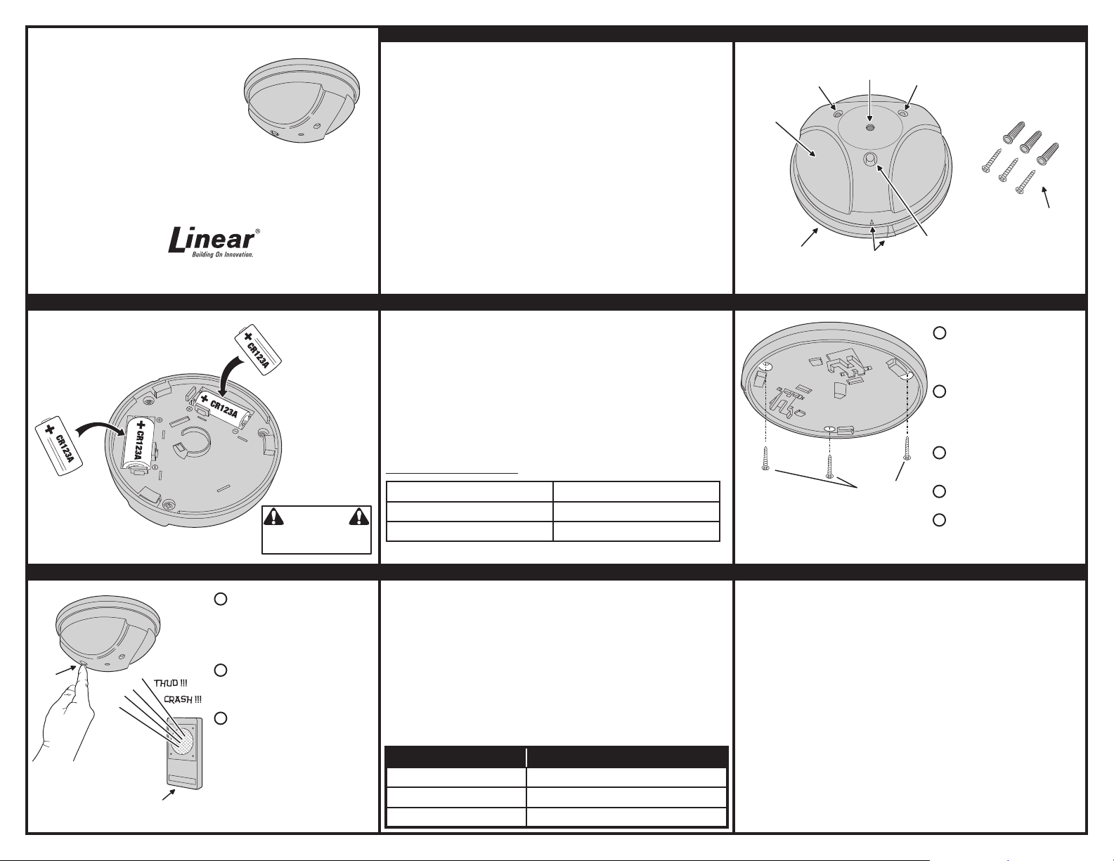
FEATURES
RED TEST AND
2ND STAGE
INDICATOR
GLASS BREAK
DETECTOR
DETECTION
MICROPHONE
Being supervised, about every 65 minutes the unit sends a status signal to update the
receiver. If the battery tests low, a low battery signal is included with any transmission.
The transmitter is powered from two 3-Volt CR123A lithium batteries (included).
An internal switch senses if the detector is removed from its base. Removing the
REMOVABLE
MOUNTING
BASE
BASE
ALIGNMENT
INDICATORS
USA & Canada (800) 421-1587 & (800) 392-0123
(760) 438-7000 - Toll Free FAX (800) 468-1340
www.linearcorp.com
detector will send a tamper signal to the receiver.
Three screws and screw anchors are provided for mounting the detector.
INSTALLING OR CHANGING BATTERIES PROGRAMMING MOUNTING THE DETECTOR
For a detail programming guide, the instruction manual should be consulted for
INSERT TWO
CR123A BATTERIES
INTO BATTERY
HOLDERS
OBSERVE
POLARITY !!!
that panel. The below guide should only be used as a reference and not as a
replacement for using the programming instructions.
1. Enter Panel Programming
2. Select Zone #
3. Enter 6 Digit ID number (located on back of unit)
4. Enter Check sum (0-9 ; A-F) (located on back of unit). Digit that follows ¨:¨ on
the Serial ID. For A-F use 0-5 (See Below)
5. Enter Point ¨3¨ - for Glass Break
6. Push On/Off to Save
Alpha Numeric Conversion
MOUNTING
SCREWS
WARNING
DANGER OF EXPLOSION IF BATTERIES ARE
INSTALLED INCORRECTLY. REPLACE ONLY
WITH THE SAME OR EQUIVALENT TYPE
RECOMMENDED BY THE MANUFACTURER.
A = *0 D = *3
B = *1 E = *4
C = *2 F = *5
NOTE: IF THE BATTERIES ARE NOT
INSTALLED, THE DETECTOR WILL
NOT ALLOW MOUNTING TO THE BASE
GREEN TEST AND
1ST STAGE
INDICATOR
TEST
BUTTON
LOCATE THE DETECTOR ON THE
1
ADJACENT OR OPPOSITE WALL
OR ON THE CEILING
15 FEET OF THE WINDOW BEING
PROTECTED
USE THE MOUNTING BASE AS A
2
TEMPLATE TO MARK THE LOCATION
OF THE THREE MOUNTING HOLES
NOTE: WHEN WALL MOUNTING,
ORIENT THE TEST BUTTON DOWN
DRILL 3/16" PILOT HOLES FOR THE
3
SCREW ANCHORS AND PUSH
THE ANCHORS INTO THE HOLES
ATTACH THE MOUNTING BASE
4
WITH THE THREE SCREWS
ATTACH THE DETECTOR TO THE
5
BASE, MATCH THE ALIGNMENT
MARKS AND TURN CLOCKWISE
MOUNTING
SCREWS
AND ANCHORS
WITHIN
DETECTOR TESTING SPECIFICATIONS
Operating Temperature: 32° to 120° F (0° to 49° C)
Operating Relative Humidity: 5 to 95%, non-condensing
Operating Frequency: 319.5 MHz
Battery Type: Two 3-Volt CR123A Lithium Batteries
Sensor Type: Single microphone,
dual-stage (thud & crash)
Approved Glass Break Simulator: Intellisense Model FG-701
The minimum size for all glass types is 11” x 11” (28 cm x 28 cm) square. Glass must
be framed, in a wall of the room or mounted in a barrier of 36” (91 cm) minimum width.
GLASS TYPE MINIMUM TO MAXIMUM THICKNESS
PLATE 1/8” TO 1/4” (3.2 mm TO 6.4 mm)
TEMPERED 1/8” TO 1/4” (3.2 mm TO 6.4 mm)
SEALED, INSULATING 1/8” TO 1/4” (3.2 mm TO 6.4 mm)
TEST
BUTTON
INTELLISENSE
MODEL FG-701
GLASS BREAK
SIMULATOR
PRESS AND HOLD THE TEST BUTTON
1
FOR 2 SECONDS, THEN RELEASE. THE
RED LED WILL LIGHT WHILE THE
BUTTON IS PRESSED, THE GREEN
LED WILL BLINK ONCE INDICATING
AUTO TEST MODE FOR 90 SECONDS.
ACTIVATE THE GLASS BREAK
2
SIMULATOR IN THE AREA OF THE
WINDOW OR WINDOWS BEING
PROTECTED.
THE DETECTOR SHOULD FIRST
3
ACKNOWLEDGE THE DETECTION
OF A THUD SOUND BY LIGHTING THE
GREEN LED, THEN LIGHT THE RED
LED WHEN IT DETECTS THE CRASH
PORTION OF THE GLASS BREAKING
SOUND
NOTE: FOR RF TEST MODE, PRESS AND
HOLD THE TEST BUTTON FOR 5 SECONDS,
THE GREEN LED WILL BLINK TWICE
AND A TEST SIGNAL IS SENT FOR 90 SECONDS
LINEAR LIMITED WARRANTY
This Linear product is warranted against defects in material and workmanship for twelve (12) months. This
warranty extends only to wholesale customers who buy direct from Linear or through Linear’s normal
distribution channels. Linear does not warrant this product to consumers. Consumers should inquire from their
selling dealer as to the nature of the dealer’s warranty, if any. There are no obligations or liabilities on the part
of Linear LLC for consequential damages arising out of or in connection with use or performance of this
product or other indirect damages with respect to loss of property, revenue, or profi t, or cost of removal,
installation, or reinstallation. All implied warranties, including implied warranties for merchantability and implied
warranties for fi tness, are valid only until the warranty expires. This Linear LLC Warranty is in lieu of all other
warranties express or implied.
All products returned for warranty service require a Return Product Authorization Number (RPA#). Contact Linear
Technical Services at 1-800-421-1587 for an RPA# and other important details.
Linear radio controls provide a reliable communications link and fi ll an important need in portable wireless
signaling. However, there are some limitations which must be observed.
✴ For U.S. installations only: The radios are required to comply with FCC Rules and Regulations as Part 15
devices. As such, they have limited transmitter power and therefore limited range.
✴ A receiver cannot respond to more than one transmitted signal at a time and may be blocked by radio signals
that occur on or near their operating frequencies, regardless of code settings.
✴ Changes or modifi cations to the device may void FCC compliance.
✴ Infrequently used radio links should be tested regularly to protect against undetected interference or fault.
✴ A general knowledge of radio and its vagaries should be gained prior to acting as a wholesale distributor or
dealer, and these facts should be communicated to the ultimate users.
This device complies with FCC Part 15 and Canada Rules and Regulations. Operation is subject to the following
two conditions: (1) This device may not cause harmful interference and (2) this device must accept any interference
received, including interference that may cause undesired operation.
Copyright © 2013 Linear Corporation 187-1133 C
IMPORTANT !!!
 Loading...