

Page 1
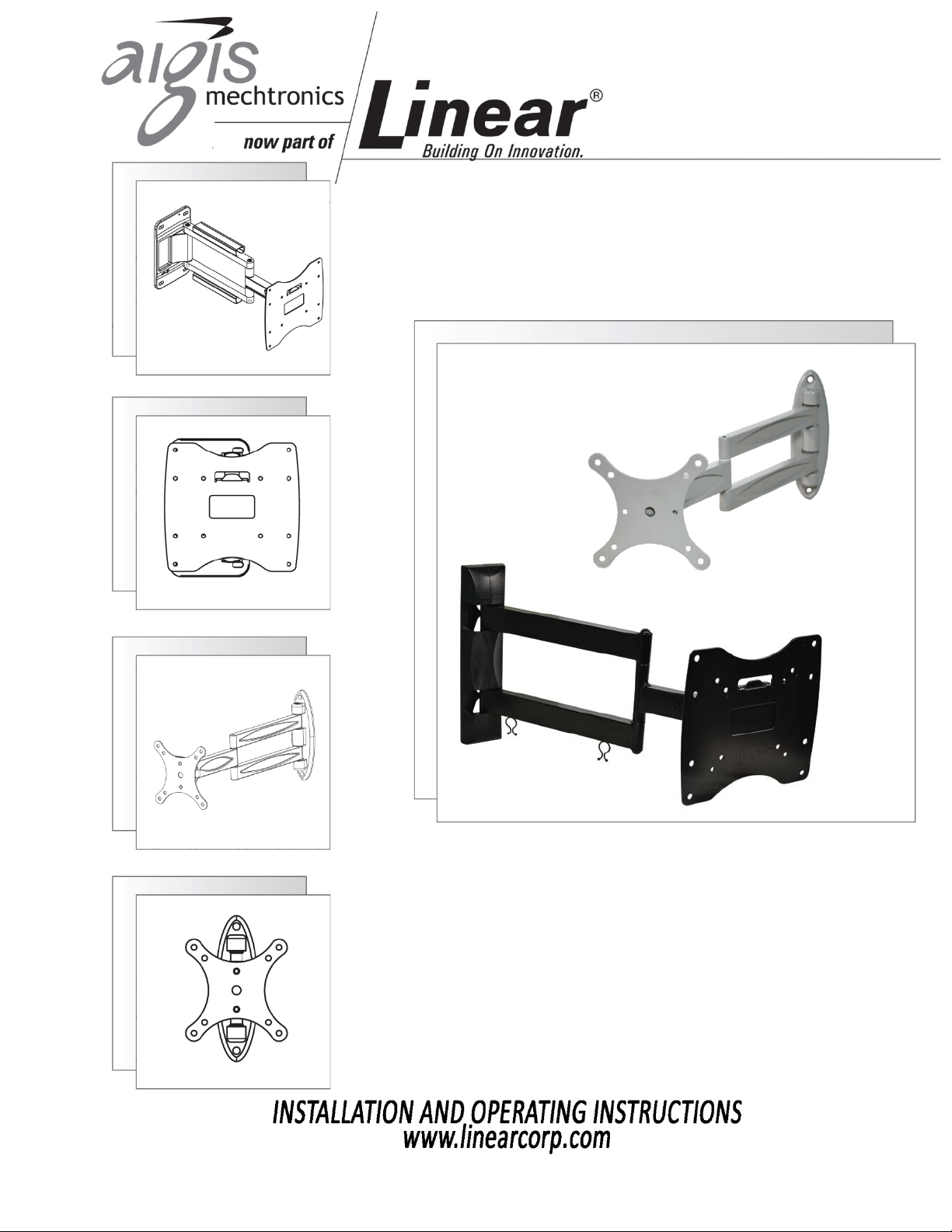
Flat Panel Wall Mounts
MT-MWB Series
Page 2

IMPORTANT SAFEGUARDS
1. Read Instructions - All the safety and operating instructions should be read before the unit is operated.
2. Retain Instructions - The safety and operating instructions should be retained for future reference.
3. Heed Warnings - All warnings on the unit and in the operating instructions should be adhered to.
4. Follow Instructions - All operating and use instructions should be followed.
5. Cleaning - Unplug the unit from the outlet before cleaning. Do not use liquid cleaners or aerosol cleaners. Use a damp cloth for cleaning.
6. Attachments - Do not use attachments not recommended by the product manufacturer as they may cause hazards.
7. Accessories - Do not place this unit on an unstable stand, tripod, bracket, or mount. The unit may fall, causing serious injury to a person and serious
damage to the unit. Use only with a stand, tripod, bracket, or mount recommended by the manufacturer or sold with the product. Any mounting of
the unit should follow the manufacturer's instructions and should use a mounting accessory recommended by the manufacturer.
An appliance and cart combination should be moved with care. Quick stops, excessive force, and uneven surfaces may cause the appliance and cart
combination to overturn.
8. Ventilation - Openings in the enclosure, if any, are provided for ventilation, to ensure reliable operation of the unit, and to protect it from
overheating. These openings must not be blocked or covered. This unit
should not be placed in a built-in installation unless proper ventilation is provided or the manufacturer's instructions have been adhered to.
9. Power Sources - This unit should be operated only from the type of power source indicated on the marking label. If you are not sure of the type of
power supply you plan to use, consult your appliance dealer or local power company. For units intended to operate from battery power or other
sources, refer to the operating instructions.
10. Grounding or Polarization - This unit may be equipped with a polarized alternating-current line plug (a plug having one blade wider than the other).
This plug will fit into the power outlet only one way. This is a safety feature. If you are unable to insert the plug fully into the outlet, try reversing
the plug. If the plug should still fail to fit, contact your electrician to replace your obsolete outlet. Do not defeat the safety purpose of the polarized
plug. Alternatively, this unit may be equipped with a 3-wire grounding-type plug, a plug having a third (grounding) pin. This plug will only fit into a
grounding-type power outlet. This is a safety feature. If you are unable to insert the plug into the outlet, contact your electrician to replace your
obsolete outlet. Do not defeat the safety purpose of the grounding-type plug.
11. Power Cord Protection - Power supply cords should be routed so that they are not likely to be walked on or pinched by items placed upon or
against them, paying particular attention to cords and plugs, convenience receptacles, and the point where they exit from the appliance.
12. Power Lines - An outdoor system should not be located in the vicinity of overhead power lines or other electric light or power circuits or where it
can fall into such power lines or circuits. When installing an outdoor system, extreme care should be taken to keep from touching such power lines
or circuits as contact with them might be fatal. U.S.A. models only - refer to the National Electrical Code Article 820 regarding installation of CATV
systems.
13. Overloading - Do not overload outlets and extension cords as this can result in a fire or electric shock.
14. Object and Liquid Entry - Never push objects of any kind into this unit through openings, as they may touch dangerous voltage points or short out
parts that could result in a fire or electric shock. Never spill liquid of any kind on the unit.
15. Servicing - Do not attempt to service this unit yourself as opening or removing covers may expose you to dangerous voltage or other hazards. Refer
all servicing to qualified service personnel.
16. Damage Requiring Service - Unplug the unit from the outlet and refer servicing to qualified service personnel under the following conditions:
a. When the power supply cord or plug is damaged.
b. If liquid has been spilled or objects have fallen into the unit.
c. If the unit has been exposed to rain or water.
d. If the unit does not operate normally by following the operating instructions. Adjust only those controls that are covered by the operating
instructions, as an improper adjustment of other controls may result in damage and will often require extensive work by a qualified technician
to restore the unit to its normal operation.
e. If the unit has been dropped or the cabinet has been damaged.
f. When the unit exhibits a distinct change in performance--this indicates a need for service.
17. Replacement Parts - When replacement parts are required, be sure the service technician has used replacement parts specified by the
manufacturer or have the same characteristics as the original part. Unauthorized substitutions may result in fire, electric shock, or other hazards.
18. Safety Check - Upon completion of any service or repairs to this unit, ask the service technician to perform safety checks to determine that the unit
is in proper operating condition.
19. Coax Grounding - If an outside cable system is connected to the unit, be sure the cable system is grounded. U.S.A. models only--Section 810 of the
National Electrical Code, ANSI/NFPA No.70-1981, provides information with respect to proper grounding of the mount and supporting structure,
grounding of the coax to a discharge unit, size of grounding conductors, location of discharge unit,connection to grounding electrodes, and
requirements for the grounding electrode.
20. Lightning - For added protection of this unit during a lightning storm, or when it is left unattended and unused for long periods of time, unplug it
from the wall outlet and disconnect the cable system. This will prevent damage to the unit due to lightning and power line surges.
Page 3

Unpacking
Unpack carefully. This is electromechanical equipment
and should be handled with care. If an item appears to
have been damaged in shipment, replace it properly in
its carton and notify the shipper. If any items are
missing, notify Linear LLC. The shipping carton is the
safest container in which the unit may be transported.
Save it for possible future use.
Service
If the unit ever needs repair service, the customer
should contact Linear LLC for a return product
authorization (RPA) and shipping instructions.
Care and Maintenance
None required.
Model Designation
MT-MWB100 Flat panel wall mount, 10”-22”
screens, 75x75mm and 100x100mm
hole patterns.
MT-MWB200 Flat panel wall mount, 22”-42”
screens, 100x100mm, 200x100mm,
200x200mm hole patterns.
Description
The MT-MWB Series of monitor wall brackets are
suitable for standard VESA compliant monitors from 1042” screen sizes. The mounts are retractable to allow
the screen to be stored against the wall and extended
for viewing. Both mounts include a swivel head with
both tilt and vertical alignment adjustments.
Hardware Kit (MT-MWB100)
2 x #14 x 2.5” Screws, Cross Recessed
2 x 10mm x 50mm Plastic Wall Anchors
4 x M4 x 25mm Bolts, Cross Recessed
4 x Nylon Spacers
Hardware Kit (MT-MWB200)
4 x 7mm x 80mm Screws, Hex Head
4 x 10mm x 60mm Plastic Wall Anchors
4 x M6 x 15mm Bolts, Cross Recessed
4 x M8 x 15mm Bolts, Cross Recessed
Tools Required (MT-MWB100)
Level
Pozidriv #2 cross recess bit or screwdriver
4mm Drill Bit
10mm Drill Bit
Drill
Tools Required (MT-MWB200)
Level
10mm Socket
12mm Socket
4mm Drill Bit
10mm Drill Bit
Drill
Installation – MT-MWB100
1. Remove product from packaging. Set hardware kit
aside.
2. Hold the mount up to the installation location and
use the flange as a template to mark the top bolt
hole.
3. Use a level to make sure the mount is vertical
before marking the lower bolt hole. Set the mount
aside.
4. If drilling into drywall:
a. Ensure there is a stud where the bolts will go.
b. Drill pilot holes using a 4mm drill bit to a depth
of 2.0” (50mm).
c. Hold the mount up to the wall and locate it
over the bolt holes.
d. Do not use the plastic wall anchors.
e. Install the #14 screws using a Pozidriv #2
(similar to Phillips) bit or screwdriver.
5. If drilling into concrete:
a. Drill pilot holes using a 10mm drill bit to a
depth of 2.5”.
b. Hold the mount up to the wall and locate it
over the bolt holes.
c. Insert the plastic wall anchors into the holes.
d. Install the #14 screws using a Pozidriv #2
(similar to Phillips) bit or screwdriver.
6. Select appropriate fasteners to attach the monitor
to the mount. Included with the mount are four M4
screws that are 25mm in length. Plastic spacers are
included in case the screws are too long for the
monitor. Position the spacers either between the
bolt head and the mount, or between the mount
3
Page 4

and the monitor. Doing the latter will help protect
Figure 1 - Rear of Mount Head
Figure 2 - Detail View
1
2
1
2
the monitor’s finish.
7. Hold the monitor up to the mount and align the top
holes. Insert the top screws and finger-tighten until
the mount can take the monitor’s weight.
8. Let the monitor rest on the mount, and install the
lower screws until tight.
9. Tighten the upper screws to complete the
installation.
10. The mount is designed to be re-positioned
repeatedly once the monitor is installed. Do not
attempt to lock the mount arms down so that they
are immobile, as this could damage the mount.
Installation – MT-MWB20
1. Re
move product from packaging. Set hardware kit
0
aside. The plastic cover over the base of the mount
is removed by pulling it apart from the centerline.
Do not use a tool to pull it apart, as this may
damage the finish.
2. Hold the mount up to the installation location and
use the flange as a template to mark the top bolt
holes.
3. Use a level to make sure the mount is vertical
before marking the lower bolt holes. Set the mount
aside.
4. If drilling into drywall:
a. Ensure there is a stud where the bolts will go.
b. Drill pilot holes using a 4mm drill bit to a depth
of 2.3” (60mm).
c. Hold the mount up to the wall and locate it
over the bolt holes.
d. Do not use the plastic wall anchors.
e. Install the #14 screws using a Pozidriv #2
(similar to Phillips) bit or screwdriver.
5. If drilling into concrete:
a. Drill pilot holes using a 10mm drill bit to a
depth of 2.5”.
b. Hold the mount up to the wall and locate it
over the bolt holes.
c. Insert the plastic wall anchors into the holes.
d. Install the #14 screws using a Pozidriv #2
(similar to Phillips) bit or screwdriver.
6. Remove the lower set of fasteners on mount head
(Figure 1, Item 1) and remove the mount head.
7. Attach this to the monitor using appropriate bolts.
M6 and M8 bolts are provided, but may not work
for every monitor.
8. Ensure the slotted flange of the mount head is
facing the TOP of the monitor when attaching the
mount head to the monitor.
9. Hang the Monitor/Mount Head assembly by
aligning the slotted flange with the tongue (Figure
2, Item 1). This will allow the monitor to hang on
the mount while the lower fasteners are reattached.
10. Tilt adjustment bolts are shown in Figure 1, Item 2.
Rotation adjustment bolts are shown in Figure 2,
Item 2.
100 0301 001 AIG 07/2012
Printed in the U.S.A.
4
 Loading...