

Page 1
INSTALLATION INSTRUCTIONS
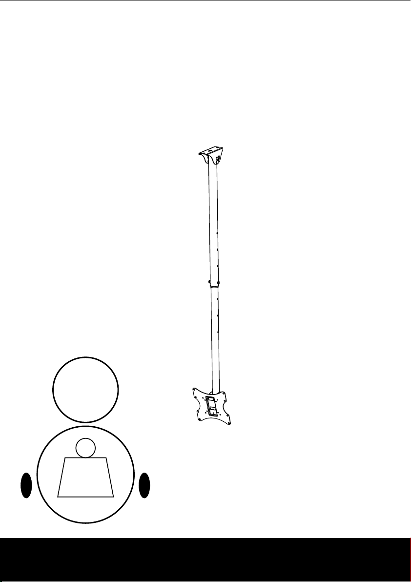
Til ting angl e:
-15° ~ 0°
20kg
(44lbs)
MAX
PLB Ceiling Mount
Model: MT-MCB-B
Max Load Capacity: 20kg(44lbs)
Page 2

NOTE: Read the entire instruction manual before you start installation and assembly.
WARNING
• Do not begin the installation until you have read and understood the instructions and
warnings contained in this installation sheet. If you have any questions regarding any
of the instruction or warning, please contact your local distributor.
• This mounting bracket was designed to be installed and utilized ONLY as specified in
this manual. Improper installation of this product may cause damage or serious injury.
• This product should only be installed by someone of good mechanical ability, with basic
building experiences and fully understanding of this manual.
• Make sure that the supporting surface will safely support the combined load of the
equipment and all attached hardware and components.
• Never exceed the maximum load capacity.
• Always use an assistant or mechanical lifting equipment to safely lift and position
equipment.
• Tighten screws firmly, but do not over tighten. Over tightening can damage the items,
greatly reducing their holding power.
• This product intended for indoor use only. Using this product outdoors could lead to
product failure and personal injury.
Page 3
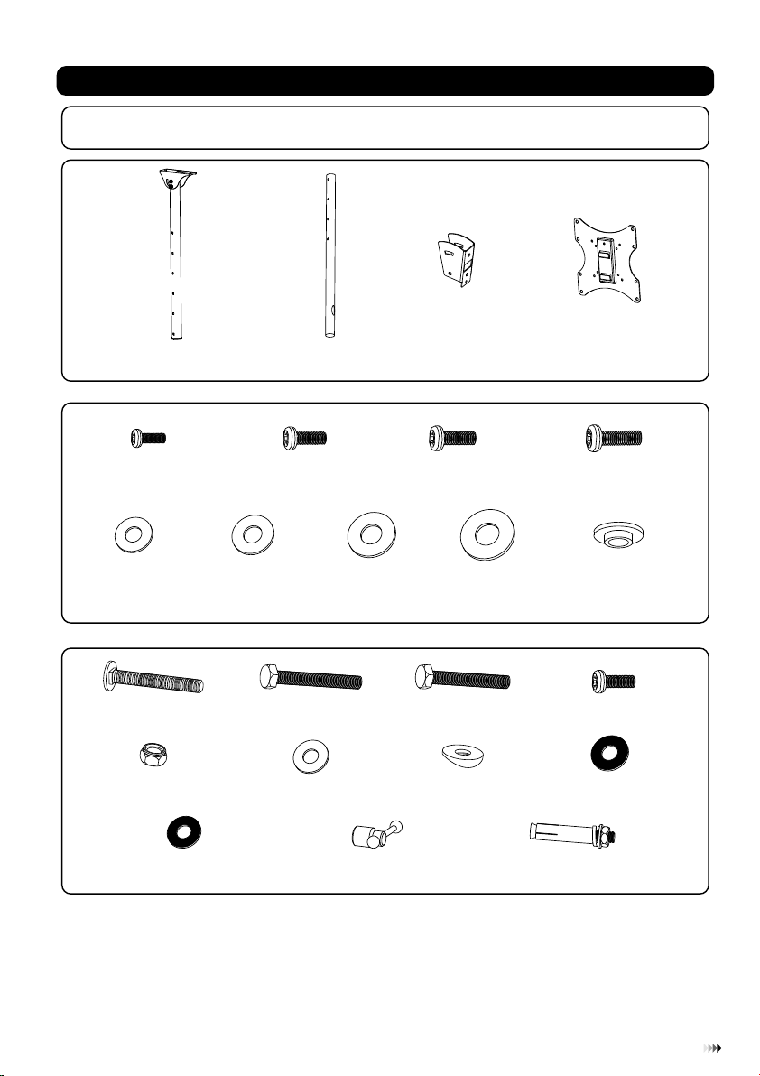
Component Checklist
IMPORTANT: Ens ure t ha t you h ave r eceiv ed al l parts a cco rding t o the c ompon ent c heckl ist p rio r to i nst all in g. If
any p ar ts ar e mis si ng or f aul ty, te lepho ne th e speci al fr anchi ser f or a repl ace ment.
outer c ol umn (x1 )
Package M
M4x10
ø ø10
D4 ( 4.5x )
washe r
M-E
Package
M8x60
M8 nut (x2)
A
(x4) M5x10 ( x4 )
M-A
D (ø .5xø )
(x1)
5 5 12
(x4)
washe r
M-F
M8x60
D8 ø8.5 ø 16 (x3)x washe r
(x4)
P-A
P-E
inner column (x1)
B
M-B
D6 (ø6. 3x ø )
washe r
M-G
(x1)
P-B
P-F
hook plate (x1)
16
(x4)
C
M6x10 ( x4 )
M-C
D8 (ø8. 3x ø )
washe r
M-H
M8x55
(x1)
P-C
washe r
P-G
(x4)
adapter bracket (x1)
16
(x4)
ø10.5 ø 20 (x1)x washe r
D
M8x15 ( x4 )
M-D
ø13.5 xø 5.5x3 .2 (x4)
M-I
M5x6
(x1)
P-D
P-H
ø8.5 ø1 7. 5 (x3)x washe r
P-I
M8 iron k no b
P-J
(x1)
Tools required
Phillips head screw driver(200mm length exclude the handle)
·
Wrench and socket
·
Electric drill and 12mm masonry bit for concrete wall installation
·
Marking pen
·
Hammer
·
M8 (x3)x70 iro n ex pansi on bolt
P-K
21
Page 4

Installing the Hook Plate
1
• Attach the hook plate to t he inner column using the app ropriate combination of screws , washers, nut and
iron knob. Tighten all s crews as shown in fig.1.1.
inner column
P-F
P-J
P-I
P-E
P-I
P-F
Installing the Column of Ceiling Mount
2
• Run power cab le through channel as shown in fig.2 .1.
• Install the inner co lumn into the outer column at d esired height and secure using scr ew (P-C), washer (P-F)
and nut (P-E) as shown i n fig.2.1.
P-G
P-G
P-H
P-I
P-A
P-B
fig. 1.1
P-C
P-F
P-E
fig. 2.1
Page 5

Solid B rick an d Concrete Block Mounti ng:
3
WARNING
• When installing PLB ceiling mounts on cinder block, verify that you have a minimum of 1-3/8”
of actual concrete thickness in the hole to be used for the concrete anchors. Do not drill into
mortar joints! Be sure to mount in a solid part of the block, generally 1” minimum from the side
of the block. It is suggested electric drill on slow setting is used to drill the hole instead of a
hammer drill to avoid breaking out the back of the hole when entering a void or cavity.
• Installer must verify that the supporting surface will safely support the combined load of the
equipment and all attached hardware and components.
• Use the ceiling plate as a template to mark three holes locations on the ceiling as shown in fig.3.1.
• Pre-drill these holes with a 12mm masonry bit to at least 45mm in depth. Insert an iron expansion bolt into each of
these holes. Attach the ceiling plate to the ceiling using other parts of iron expansion bolt as shown in fig.3.1.
Note: This product can be installed in both flat and bevel roof.
P-K
flat roof installation
bevel roof installation
fig. 3.1
43
Page 6

Installing Adapter Bracket
4
• To prevent scratching the screen, set a cloth on a flat, level surface that will support the weight of the screen.
• Place screen face side down. Place dapter racket on the back of screen, align to holes, as shown in fig.4
and fig.4.2.
the a b .1
• Attach the adapter bracket to the back of the screen using appropriate combination of screws and washers. as
shown in fig.4.1 and fig.4.2.
M-C
M-A
M-B
M-I
M-D
fig. 4.1
M-G
M-H
M-E
M-F
Hang TV onto the Hook plate
5
Warning: A minimum of two qualified people are required for this operation.
• Hook the TV onto the hook plate as shown in fig. 5.1.
• Tighten the safety screws with a proper screw driver as shown in fig. 5.1.
Important: Make sure the TV is correctly hooked and the safety locking screws are locked safely before
releasing the TV.
fig. 4.2
Page 7

hook plate
iron knob
P-D
Pitching Angle Adjus tment
3
6
Use the iron knob to adjust your TV to the desire d ang le, a nd th en ti ghten the iron kn ob. t he pi tch ing angle
can be adjusted betw een - 15° ~ 0 ° as sh own i n fig .6.1.
fig. 5.1
65
Page 8

0°
-15°
Maintenance
Once you have mounted the bracket and the fl at scr een, check that th ey are sufficien tly se cure and safe to
use. You should check wheth er scr ews ar e fixe d well each tw o mont hs. If you have any dou bts re garding the
install ation, please consult our retailer or service depart ment for det ails.
7
fig. 6.1
 Loading...