

Page 1
USA & Canada (800) 421-1587 & (800) 392-0123
(760) 438-7000 - Toll Free FAX (800) 468-1340
www.linearcorp.com
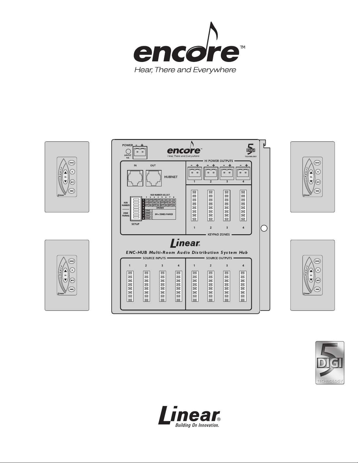
Multi‑Room Audio
Distribution System
Installation & Setup
Instructions
Page 2
Safety Information and Cautions
CAUTION
RISK OF ELECTRIC SHOCK
DO NOT OPEN
CAUTION: TO REDUCE THE RISK OF ELECTRIC SHOCK
DO NOT REMOVE COVER (OR BACK)
NO USER-SERVICEABLE PARTS INSIDE
REFER SERVICE TO QUALIFIED PERSONNEL
Explanation of Graphic Warning Symbols
This symbol is intended to aler t the user to the presence of
un-insulated “dangerous voltage” within the product’s enclosure that
may be of sufficient magnitude to constitute a risk of electric shock.
This symbol is intended to alert the user to the presence of important
operating and maintenance (servicing) instructions in the literature
accompanying the device.
★ WARNING! To prevent fire or shock hazard, do not expose this
device to rain, water, or wet locations.
General Wiring Cautions
DO NOT USE EXCESSIVE FORCE ON PUNCH-DOWN TERMINALS! IF •
USING AN IMPACT TYPE 110 PUNCH-DOWN TOOL, SET THE FORCE
ADJUSTMENT TO “LOW” BEFORE TERMINATING CAT-5 CABLES.
The 120 VAC line to the structured wiring enclosure •
junction box must be run by a licensed electrician.
Individual CAT-5 cable runs from the hub to any keypad or •
source input wall plate should not exceed 500 feet.
Label all cables for identification at the hub.•
DO NOT SPLICE CABLES! Splices are unreliable and •
defeat the signal isolation properties of the cable.
DO NOT STAPLE CABLES! Staples cause shorts.•
DO NOT RUN 120 VAC ELECTRICAL WIRES INSIDE KEYPAD OR •
SOURCE INPUT WALL PLATE JUNCTION BOXES. If you encounter
120 VAC wires running through these junction boxes, you must have
a qualified electrician rerun those wires around the junction box.
KEEP CABLES AT LEAST 18 INCHES FROM FLUORESCENT •
LIGHT FIXTURES, DIMMER CONTROLS, AND ALL OTHER WIRING.
This includes AC wiring, security cable, cordless phone units, and
other control wires. These can cause a “hum” or “buzzing” sound.
Keep all cables away from objects such as heating and air •
conditioning ducts, metal construction plates, and anything
else with sharp edges that can damage cables.
Keypad Cautions
DO NOT install keypads in saunas. They will not •
withstand the extreme heat and moisture.
Important Safety Notes
POWER SOURCE This unit should only be connected to a
110-120 VAC power source as marked on the unit.
GROUNDING OR POLARIZATION Do not defeat the safety purpose
of the polarized or grounding-type plug. A polarized plug has two
blades with one wider than the other. A grounding type plug has two
blades and a third grounding prong. The wide blade or the third prong
are provided for your safety. If the provided plug does not fit into your
outlet, consult an electrician for replacement of the obsolete outlet.
NON-USE PERIODS Always turn the unit off when it is not
being used or left unattended for long periods of time.
OBJECT AND LIQUID ENTRY Never push objects of any kind into
the unit through the cabinet slots as they may touch dangerous
voltage points or short out parts that could result in a fire or
electric shock. Never spill liquid of any kind on the unit.
CLEANING Unplug the unit from the wall outlet before cleaning or
polishing it. Do not use liquid cleaners, aerosol cleaners, gasoline or other
flammable fluid. Clean the exterior of the unit with a slightly damp cloth.
WATER AND MOISTURE Do not use power line operated units near
water - for example, near a bathtub, washbowl, kitchen sink, or laundry
tub, in a wet basement, or near a jacuzzi or swimming pool.
VENTILATION The appliance should be situated so that its location or
position does not interfere with its proper ventilation. For example, the
unit should not be situated on a bed, sofa, rug or placed in a built-in
installation that may block the flow of air through the ventilation openings.
POWER CORD PROTECTION Power supply cords should be routed so
that they are not likely to be walked on or pinched by items placed upon
or against them paying particular attention to cords at plugs, convenience
receptacles, and the point where they exit from the appliance.
READ INSTRUCTIONS All the safety and operating instructions
should be read before the product is operated.
RETAIN INSTRUCTIONS The safety and operating
instructions should be retained for future reference.
HEED WARNINGS All warnings on the product and in
the operating instructions should be adhered to.
FOLLOW INSTRUCTIONS All operating and
use instructions should be followed.
ATTACHMENTS Do not use attachments not recommended
by the product manufacturer as they may cause hazards.
ACCESSORIES To prevent injury, this apparatus must be securely
attached to the floor/wall in accordance with the Installation Instructions.
OVERLOADING Do not overload wall outlets, extension cords, or integral
convenience receptacles as this can result in a risk of fire or electric shock.
REPLACEMENT PARTS When replacement parts are required, be
sure the service technician has used replacement parts specified by
the manufacturer or have the same characteristics as the original part.
Unauthorized substitutions may result in fire, electric shock, or other hazards.
SAFETY CHECK Upon completion of any service or repairs to
this product, ask the service technician to perform safety checks
to determine that the product is in proper operating condition.
WALL OR CEILING MOUNTING The product should be mounted
to a wall or ceiling only as recommended by the manufacturer.
HEAT The product should be situated away from heat
sources such as radiators, heat registers, stoves, or other
products (including amplifiers) that produce heat.
Page 3

Table of Contents
Introduction ....................................................................................................................................2
System Components ..................................................................................................................... 3
ENC-HUB System Hub ..............................................................................................................3
ENC-PS Power Supply ...............................................................................................................3
ENC-DRS Keypad ...................................................................................................................... 3
ENC-SIWP Source Input Wall Plate ........................................................................................... 3
ENC-LIWP Local Input Wall Plate ..............................................................................................3
ENC-REM Basic Remote Control ............................................................................................... 3
ENC-LRM Learning Remote Control .......................................................................................... 3
ENC-DRSFA-SL-4 Screwless Faceplate Kit (4-pack) (Almond) ................................................. 3
ENC-DRSFB-SL-4 Screwless Faceplate Kit (4-pack) (Black) .................................................... 3
ENC-DRSFW4 Faceplate Kit (4-pack) (White) ...........................................................................3
ENC-DRSFB4 Faceplate Kit (4-pack) (Black) ............................................................................3
ENC-DRSFA4 Faceplate Kit (4-pack) (Almond) ......................................................................... 3
2171-4 Single-head IR Emitter (4-pack) ..................................................................................... 3
Hub and Power Supply Setup ....................................................................................................... 4
Structured Wiring Enclosure .......................................................................................................4
Mounting Bracket Installation ..................................................................................................... 4
Hub and Power Supply Installation ............................................................................................. 4
Zone Pairing ...............................................................................................................................4
Expansion Hub Setup ...................................................................................................................5
Expansion Hub Installation ......................................................................................................... 5
Source Input Wall Plate Setup ...................................................................................................... 6
Input Gain Switches ...................................................................................................................6
IR Out Connection ...................................................................................................................... 6
Source Input Wall Plate Installation ............................................................................................6
Keypad Setup .................................................................................................................................7
Keypad Installation .....................................................................................................................7
Optional External IR Target Connection ..................................................................................... 7
Speaker Connection ................................................................................................................... 7
Local Input Wall Plate Setup ......................................................................................................... 8
Input Gain Switches ...................................................................................................................8
IR Out Connection ...................................................................................................................... 8
Local Input Wall Plate Installation ............................................................................................... 8
Final Connections and Testing ..................................................................................................... 9
Audio Source Component Connections ..................................................................................... 9
Connect Power ........................................................................................................................... 9
Basic System Testing .................................................................................................................9
Specifications .............................................................................................................................. 10
Limited Warranty ..........................................................................................................................10
1
Page 4
Introduction
8-OHM
SPEAKERS
ENC-DRS
KEYPAD
ENC-LIW P
LOCAL INPUT
WALL PLATE
8-OHM
SPEAKERS
ENC-LIW P
LOCAL INPUT
WALL PLATE
8-OHM
SPEAKERS
ENC-LIW P
LOCAL INPUT
WALL PLATE
8-OHM
SPEAKERS
ENC-LIW P
LOCAL INPUT
WALL PLATE
8-OHM
SPEAKERS
8-OHM
SPEAKERS
MP3
PLAYER
GAME
BOX
ENC-PS
POWER
SUPPLY
ENC-PS
POWER
SUPPLY
ENC-HUB
SYSTEM
HUB
ENC-HUB
EXPANSION
HUB
HI-POWER WIRE
(16 AWG)
SPEAKER ZONE
CABLES (CAT-5 )
HUBNET
EXPANSION
CABLE
(CAT-5)
SOURCE
INPUT
CABLES
(CAT-5)
SPEAKER WIRE
(16 AWG)
SOURCE
OUTUT
CABLES
(CAT-5)
ENC-SIWP
SOURCE INPUT
WALL PLATE
ENC-SIWP
SOURCE INPUT
WALL PLATE
ENC-SIWP
SOURCE INPUT
WALL PLATE
ENC-SIWP
SOURCE INPUT
WALL PLATE
CD PLAYER
SATELLITE RAD IO
COMPUTER
STEREO
RECEIVER
ZONE 1
ZONE 2
ZONE 3
ZONE 4
ZONE 5ZONE 6
2171-4
IR EMITTER
2171-4
IR EMITTER
2171-4
IR EMITTER
HUBNET
EXPANSION
SYSTEM
BASE
SYSTEM
ENC-DRS
KEYPAD
ENC-DRS
KEYPAD
ENC-DRS
KEYPAD
ENC-DRS
KEYPAD
ENC-DRS
KEYPAD
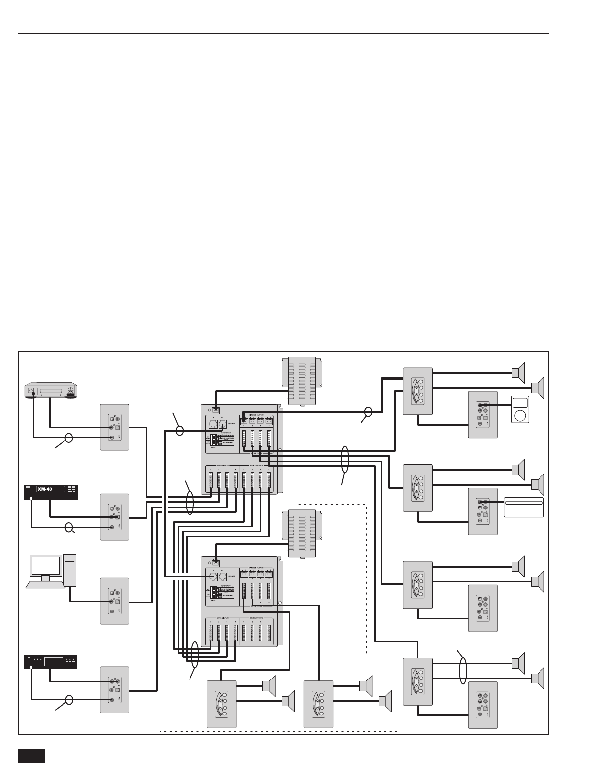
The Encore! Multi-Room Audio Distribution System is an
expandable system that distributes four analog or digital audio
sources over Cat-5 cable to four independent speaker zones. Each
speaker zone features a backlit keypad with an integrated digital
amplifier that selects the audio source and controls the volume,
tone, balance, loudness, and all other functions of the system. The
system can be expanded with up to eight distribution hubs for a
total of 32 speaker zones.
Each keypad (Model ENC-DRS) serves as a speaker zone
controller for the system. Up to four keypads can be connected to
each hub. Each keypad contains a Class D digital stereo amplifier
providing up to 60 watts maximum output power (30 watts per
channel) and is designed to connect to a pair of 4, 6, or 8-ohm
speakers.
Source input wall plates (Model ENC-SIWP) serve as primary
audio source inputs and wire directly to the hub. Up to four source
input wall plates can be connected to the “primary” or “base” hub.
Local input wall plates (Model ENC-LIWP) serve as a local audio
source input at each speaker zone. Local input wall plates connect
directly to the keypad.
The keypads select between the four primary hub audio sources
from source input wall plates, or from its local audio source
connected to a local input wall plate. Both input wall plates feature
a high quality analog-to-digital converter that encodes analog
source material to a digital audio format for the system. All system
connections are with Cat-5 cable, the keypads and both types of
wall plates mount in a single-gang or larger junction boxes.
The system features IR remote control. An infrared repeater system
monitors the infrared receivers at each keypad and repeats the
infrared remote control signals to the audio source components
through infrared emitters connected to the wall plates. IR emitters
are sold in a 4-pack as Model 2171-4.
Two remote controls are available. The basic remote control
(Model ENC-REM) is a miniature unit that can select the audio
source, control the keypad’s volume, and control mute and power.
The larger learning remote control (Model ENC-LRM) has all of
the features of the basic remote with the addition of a built-in IR
code library and IR learning capability allowing it to control virtually
any audio source component. The learning remote also has macro
capabilities that allow programming multiple key sequences.
Features
Pure digital audio delivers crystal clear •
sound to all zones with no signal loss
Class D digital amplifier in each keypad •
providing 60 watts of output power
Four speaker zones expandable to 32 speaker zones•
IR receiver built into each keypad, IR emitter •
output on source input wall plates
Cat-5 wiring•
Keypads and audio input wall plates mount •
in single-gang junction boxes
2
Example Six Zone InstallationFigure 1.
Page 5

System Components
Audio
In
LR
Coax In
Optical In
Analog
Optical
Coax
IR Out
Clip
Audio
In
LR
1
2
Coax In
Optical In
Analog
Optical
Coax
IR Out
Clip
ENC-HUB
System Hub
Pure digital audio delivers crystal clear •
sound to all zones with no signal loss
Four speaker zones•
Expandable to 32 speaker zones•
Cat-5 wiring•
Mounts in structured wiring •
enclosure or on H275 bracket
Four high power terminals •
for long keypad runs
ENC-PS
Power Supply
120 VAC input, 26 VDC •
@ 8 Amp output
Output cable has connector for hub•
Green power indicator•
Mounts in structured wiring •
enclosure or on H275 bracket
ENC-DRS
Keypad
Controls speaker zone’s volume, •
tone, balance, and loudness
Integrated Class D digital amplifier•
Built-in IR receiver for IR remote •
control of source components
Blue LED backlit buttons•
White keypad bezel and faceplate•
ENC-SIWP
Source Input Wall Plate
Stereo analog audio inputs•
Coaxial digital and SPDIF •
optical digital audio inputs
High quality analog-to-digital converter•
IR emitter output•
ENC-LIWP
Local Input Wall Plate
Coaxial digital and SPDIF •
optical digital audio inputs
Two stereo analog audio inputs•
High quality analog-to-digital converter•
IR emitter output•
ENC-REM
Basic Remote Control
Miniature size•
Selects audio source•
Adjusts speaker volume •
and has mute function
Remotely controls system power•
ENC-LRM
Learning Remote Control
Remote can learn codes from •
other remotes, providing ability
to control source components
from a remote location
Selects audio source•
Adjusts speaker volume •
and has mute function
Remotely controls system power•
Programmable macros with •
up to 19 steps each
ENC-DRSFA-SL-4
Screwless Faceplate Kit
(4-pack) (Almond)
Four almond keypad bezels•
Four almond screwless faceplates•
Changes keypad color or replaces •
damaged or worn faceplate
For ENC-DRS keypad•
ENC-DRSFB-SL-4
Screwless Faceplate Kit
(4-pack) (Black)
Four black keypad bezels•
Four black screwless faceplates•
Changes keypad color or replaces •
damaged or worn faceplate
For ENC-DRS keypad•
ENC-DRSFW4
Faceplate Kit
(4-pack) (White)
Four white keypad bezels•
Four white faceplates•
Includes matching plate screws•
For changing color or replacing •
damaged or worn faceplates
For ENC-DRS keypad, ENC-SIWP •
and ENC-LIWP input plates.
ENC-DRSFB4
Faceplate Kit
(4-pack) (Black)
Four black keypad bezels•
Four black faceplates•
Includes matching plate screws•
For changing color or replacing •
damaged or worn faceplates
For ENC-DRS keypad.•
ENC-DRSFA4
Faceplate Kit
(4-pack) (Almond)
Four almond keypad bezels•
Four almond faceplates•
Includes matching plate screws•
For changing color or replacing •
damaged or worn faceplates
For ENC-DRS keypad.•
2171-4
Single-head IR Emitter
(4-pack)
Single-head IR emitter, 4-pack•
Repeats IR signals from keypads •
to source components
Ten foot cord with mini plug•
Adhesive back on emitter•
3
Page 6

Hub and Power Supply Setup
MOUNTING
GRID
J-BOX
OUTLET
INSTALLED
IN J-BOX
The hub and power supply can mount on the grid in a Linear
structured wiring enclosure or to a universal mounting bracket
(Model H275). The bracket is included in the Model ENC-KIT-M
installation kit.
Structured Wiring Enclosure
If the hub and power supply will be mounted in a structured wiring
enclosure, follow these steps:
Determine a location for the structured wiring enclosure. Be sure power is 1.
available near the location to wire an outlet box in the enclosure.
Install a J-box in the enclosure and have a2. licensed electrician route
power to the J-box.
Install an outlet in the J-box and install an outlet cover plate.3.
➜ WARNING: Do not connect the power supply to the AC line
until after the installation is complete.
Mounting Bracket Installation
If the hub and power supply will be mounted on a Model H275
mounting bracket, follow these steps:
Determine a location for the mounting bracket. Be sure power is available 1.
near the location to wire an outlet box next to the mounting bracket
location.
Use four screws to mount the H275 bracket on a suitable mounting 2.
surface.
Have a3. licensed electrician install an outlet in a J-box near the mounting
bracket. Install an outlet cover plate.
➜ WARNING: Do not connect the power supply to the AC line
until after the installation is complete.
Structured Wiring Enclosure MountingFigure 2.
Hub and Power Supply Installation
The hub and power supply mount to the grid holes in the structured
wiring enclosure or on the universal mounting bracket.
Insert the hub into a set of grid mounting holes. Secure the hub with the 1.
snap lock retainer.
Insert the power supply into a set of grid mounting holes. Secure the power 2.
supply with the snap lock retainer.
Connect the power supply’s DC output cable to the hub. The cable has a 3.
push-on terminal block that connects to the hub’s POWER connector.
Zone Pairing
Zone pairing is optional. It allows simultaneous control of two or
more speaker zones. A typical use would be in large rooms with
multiple keypads and speakers. Paired zones can be controlled
from any keypad in the pair, each keypad and speaker zone will
perform identically.
Zone pairing is controlled by the SETUP switch on each hub.
Switch positions 5-8 select which zones to pair.1.
To pair two or more speaker zones, set the 2. SETUP switch position to ON
for any of the four speaker zones.
SWITCH # SPEAKER ZONE
5 ZONE 1
6 ZONE 2
7 ZONE 3
8 ZONE 4
J-box Installed in Enclosure for AC PowerFigure 3.
H275 Universal Mounting BracketFigure 4.
Hub and Power Supply Installation in CabinetFigure 5.
4
Page 7

Additional hubs and power supplies can be added to the system
HUBNET
CONNECTORS
HUB
NUMBER
SWITCHES
ENC-PS
POWER
SUPPLY
ENC-HUB
SYSTEM
HUB #1
ENC-PS
POWER
SUPPLY
ENC-HUB
SYSTEM
HUB #2
ENC-PS
POWER
SUPPLY
ENC-HUB
SYSTEM
HUB #3
ENC-SIWP
SOURCE
INPUT
WALL PLATES
ENC-DRS KEYPA DS ENC-DRS KEYPA DS ENC-DR S KEYPADS
to increase the number of speaker zones available. Up to seven
additional hubs can be connected for a maximum of 32 speaker
zones.
Expansion hubs share the same four source inputs as the first hub
and each control their own four speaker zones.
Expansion Hub Installation
Expansion hubs can be mounted near the first hub, or mounted in
a remote location near the speaker zones to be controlled.
Mount the expansion hubs and power supplies in structured wiring 1.
enclosures or on the universal mounting brackets.
Connect the power supply output cable to each associated hub.2.
Use Cat-5 cables with RJ-45 connectors to interconnect each hub. Connect 3.
to the HUBNET OUT connector on the first hub, then to the HUBNET IN
connector on the next hub. Continue interconnecting the hubs using the
HUBNET IN and OUT connectors until all the hubs are connected.
Use Cat-5 cables to interconnect the hub sources. Each hub has four 4.
SOURCE INPUT and four SOURCE OUTPUT Type 110 punch-down
connectors. Start at the first hub and connect cables to each of the
SOURCE OUTPUT connectors. Route those cables to the next hub and
connect them to the same source number SOURCE INPUT connectors.
Continue interconnecting the hub source outputs and inputs until all the
hubs are connected.
Set the Hub Numbers using positions 1-3 of the 5. SETUP switch on each
hub. Each hub must be set to a unique number.
Expansion Hub Setup
HUBNET Connector and Setup SwitchFigure 6.
SWITCH
#
1
2
3
HUB NUMBER
1 2 3 4 5 6 7 8
OFF OFF OFF OFF ON ON ON ON
OFF OFF ON ON OFF OFF ON ON
OFF ON OFF ON OFF ON OFF ON
T-568A Wiring Standard for Cat-5 in RJ-45Figure 7.
Example 3 Hub, 12 Zone SystemFigure 8.
5
Page 8

Source Input Wall Plate Setup
Audio
In
LR
Coax In
Optical In
Analog
Optical
Coax
IR Out
Clip
CONNECT CAT-5
CABLE FROM HUB
TO WALL PLATE
GAIN SWITCHES
SWITCHES 1-2
ADD GAIN FOR
THE RIGHT CHANNEL
SWITCHES 3-4
ADD GAIN FOR
THE LEFT CHANNEL
INSTALL SOURCE INPUT
WALL PLATE INTO THE
J-BOX AND SECURE IT
WITH THE TWO MOUNTING
SCREWS
BLUE POST
ORANGE POST
BROWN POST
GREEN POST
BLUE STRIPE
BLUE SOLID
ORANGE STRIPE
ORANGE SOLID
GREEN STRIPE
GREEN SOLID
BROWN STRIPE
BROWN SOLID
110 PUNCH DOWN
STANDARD FOR
CAT-5 CABLE
WIRE ALL 110 PUNCH DOWN
CONNECTORS THIS WAY
The system supports up to four audio input sources. Each audio
source component connects to a source input wall plate (Model
ENC-SIWP).
The source input wall plates can connect to analog stereo audio,
coaxial digital audio, or optical digital audio provided by the source
component. The audio input type is selected by the input selector
switch on the face of the wall plate.
Input Gain Switches
The source input wall plate has internal switches for adding gain to
low level audio signals. In most cases these switches can be left in
the OFF position for no increase in gain.
To add gain to the audio signal at the wall plate, set the switches
as shown in the table below:
SWITCH #
GAIN
RIGHT CHANNEL LEFT CHANNEL
1 2 3 4
+0db OFF OFF OFF OFF
+4db ON OFF ON OFF
+8db OFF ON OFF ON
+10db ON ON ON ON
The clipping indicator will light if the signal level is too high.
IR Out Connection
The source input wall plate features an IR OUT jack for connection
to an infrared emitter. The infrared emitters have an adhesive back
so they can be attached to the source component’s faceplate near
the component’s infrared sensor. Each keypad has an infrared
sensor that will repeat a remote control’s signal using the emitters.
This allows controlling the selected source component remotely
from any keypad location.
Source Input Wall Plate Installation
Source input wall plates should be mounted in locations where
audio source components will be placed. Each source component
will have an audio connection to the wall plate using coax or optical
cable, and an infrared emitter wire connection.
For installations where the audio source components are located
in the same vicinity, a double, triple, or quad J-box can be used to
mount multiple source input wall plates.
Determine the location for the source input wall plates and install one or 1.
more J-boxes.
Route Cat-5 cable from the hub to each of the source input wall plate 2.
locations.
Connect the cables to the Type 110 punch-down 3. SOURCE INPUT
connectors on the hub. Use Type RJ-45 connectors on the wall plate end
of the cable.
Install the wall plate into the J-box and cover it using a Decora type wall 4.
plate.
Source Input Wall PlateFigure 10.
Source Input Wall Plate ConnectionFigure 11.
Source Input Wall Plate Gain SwitchesFigure 12.
6
Source Input Wall PlateFigure 9.
Source Input Wall Plate MountingFigure 13.
Page 9

The keypads (Model ENC-DRS) are wired to the hub with Cat-5
PUNCH DOWN CAT-5
CABLE FROM HUB
TO KEYPAD HUB
CONNECTOR
CONNECT 16 AWG
POWER WIRE IF
HI POWER HUB
OUTPUTS ARE USED
TO HUB
LOCAL INPUT
PLATE CONNECTOR
HUB
CONNECTOR
TO HUB
TO REMOTE IR
SENSOR
PLUG REMOTE IR
SENSOR INTO
EXTERNAL IR
CONNECTOR
RED
TO HUB
TO
SPEAKERS
RIGHT
RIGHT
LEFT
LEFT
CONNECT SPEAKERS
TO THE KEYPAD
WITH 16 AWG WIRE
SPEAKER TERMINAL BLOCK
cable. Each keypad contains a Class-D digital amplifier and
connects to a pair of stereo speakers.
Power for the keypad is normally supplied from the hub through the
Cat-5 cable. As an option to support longer cable runs and to prevent
voltage drop, the hub provides four HI POWER output terminals. The
HI POWER terminals support 2-conductor 16-gauge wire, and are
recommended for keypad installations greater than 150’ from the
hub or where maximum amplifier output will be required. See the
table below for keypad power ratings and wiring lengths.
POWER WIRES TO KEYPAD
CAT-5 ONLY
LENGTH IN FEET
6 FEET UP TO 150 FEET 40 Watts/CH 30 Watts/CH
50 FEET 29 Watts/CH 22 Watts/CH
100 FEET 23 Watts/CH 17 Watts/CH
150 FEET 17 Watts/CH 13 Watts/CH
CAT-5 PLUS
16 GAUGE POWER
WIRE FROM HUB
CONTINUOUS AVERAGE OUTPUT POWER
PER CHANNEL (< 1% THD)
6-OHM LOAD 8-OHM LOAD
Each keypad can connect to a local input wall plate (Model
ENC-LIWP). The local input wall plate can be used for an audio
source connection at the keypad’s location. See the next section
for installation of local input plates.
Keypad Installation
Determine the locations for the keypads. Be sure there is wiring access to 1.
the hub, the speakers, and the local input wall plates (if used).
Install a J-box about 56” to 60” above the floor level to mount the keypad.2.
➜ WARNING: Do not mount the keypad in the same J-box as
high voltage devices such as a light switch or outlet.
Route Cat-5 cable from the hub location to the keypad J-box. If using the 3.
HI POWER hub outputs, also route 16-gauge 2-conductor wire from the
hub to the keypad J-box.
Using a Type 110 punch-down tool, connect the keypad’s Cat-5 cable to 4.
one of the KEYPAD ZONE terminals on the hub. If using the HI POWER
hub outputs, connect the 2-conductor wire to one of the HI POWER
OUTPUT terminals on the hub. OBSERVE POLARITY!
Connect the keypad end of the Cat-5 cable to the keypad’s 5. J1 (HUB)
terminals. If using the HI POWER hub outputs, connect the 2-conductor
power wire to the keypad’s TB1 (26 VDC) terminals. OBSERVE
POLARITY!
Keypad Setup
KeypadFigure 14.
Keypad ConnectionsFigure 15.
Optional External IR Target Connection
The keypads support connection to an external IR target. An
external target is useful in some installations where the room
layout requires a remote IR target distant from the keypad.
Mount the external IR target at the desired location.1.
Route cable for the external IR target from the target’s location to the 2.
keypad J-box.
Connect the cable to the IR target and to the 3-pin header block supplied 3.
with the keypad.
Attach the 3-pin header block to the 3-pin 4. J3B header on the keypad.
Note: Red wire position (see Figure 16).
Speaker Connection
One pair of stereo speakers connects to the keypads.
Install the pair of speakers for the keypad’s zone.1.
Route 16-gauge speaker cable from the speakers to the keypad J-box.2.
Connect the speaker cable at the speaker end and to the keypad’s left and 3.
right speaker terminals. OBSERVE POLARITY!
Install the keypad into the J-box and cover it using a Decora4.
®
type wall plate.
External IR Target ConnectionsFigure 16.
Speaker ConnectionsFigure 17.
7
Page 10

Local Input Wall Plate Setup
Audio
In
LR
1
2
Coax In
Optical In
Analog
Optical
Coax
IR Out
Clip
CONNECT CAT-5 CABLE
FROM KEYPAD TO
LOCAL INPUT
WALL PLATE
INPUT 1
INPUT 2
GAIN SWITCHES
SWITCHES 1-2
ADD GAIN FOR
THE RIGHT CHANNEL
SWITCHES 3-4
ADD GAIN FOR
THE LEFT CHANNEL
INSTALL LOCAL INPUT
WALL PLATE INTO THE
J-BOX AND SECURE IT
WITH THE TWO MOUNTING
SCREWS
Each keypad supports an optional connection to a local input
wall plate (Model ENC-LIWP). The local input plate provides a
connection point for a local audio source in the same room as the
speaker zone, such as an iPod, MP3 player, or a game box.
The local input wall plate connects directly to the keypad with
Cat-5 cable and mounts in a single-gang J-box. It features two sets
of stereo RCA analog audio inputs, a coaxial digital audio input,
an SPDIF optical digital audio input, an IR emitter output jack, a
source selector switch, gain switches, and a clipping indicator.
The input selector switch determines which input is active
(Analog #2, Optical, or Coax). The Analog #1 input (the top two
RCA jacks) has a special override feature. When an audio signal
is detected at this input, it will override the other local wall plate
inputs regardless of the position of the input selector switch. When
the signal at the Analog #1 input ceases, after about 10 seconds,
the local input wall plate will switch to the source determined by the
position of the input selector switch.
Input Gain Switches
The local input wall plate has two sets of internal switches for
adding gain to low level audio signals. Switch #1 is for Input #1,
Switch #2 is for Input #2. In most cases these switches can be left
in the OFF position for no increase in gain.
To add gain to the audio signal at the wall plate, set the switches
as shown in the table below:
Local Input Wall PlateFigure 18.
SWITCH #
GAIN
RIGHT CHANNEL LEFT CHANNEL
1 2 3 4
+0db OFF OFF OFF OFF
+4db ON OFF ON OFF
+8db OFF ON OFF ON
+10db ON ON ON ON
The clipping indicator will light if the signal level is too high.
IR Out Connection
The local input wall plate features an IR OUT jack for connection to
an infrared emitter. The infrared emitter has an adhesive back so
it can be attached to the source component’s faceplate near the
component’s infrared sensor. The keypad has an infrared sensor
that will repeat a remote control’s signal using the emitters. This
allows controlling the selected source component remotely from
any keypad location.
Local Input Wall Plate Installation
The local input wall plate is usually installed near the keypad.
Determine the location for the local input wall plate and install a J-box.1.
Route Cat-5 cable from the keypad to the local input wall plate J-box.2.
Connect the cable to the Type 110 punch-down 3. J2 (LOCAL) connector on
the keypad. (See Figure 15 for the connector location, see Figure 9 for the
110 punch down wiring standard.) Use a Type RJ-45 connector on the wall
plate end of the cable.
Install the wall plate into the J-box and cover it using a Decora type wall 4.
plate.
8
Local Input Wall Plate ConnectionsFigure 19.
Local Input Wall Plate Gain SwitchesFigure 20.
Local Input Wall Plate MountingFigure 21.
Page 11

Final Connections and Testing
Analog
Optical
Coax
Analog
Optical
Coax
Analog
Optical
Coax
ANALOG STEREO
AUDIO SOURCE
COAX DIGITAL
AUDIO SOURCE
OPTICAL DIGITAL
AUDIO SOURCE
HUB
POWER
INDICATOR
After the installation is complete, the audio source components will
need to be connected. After connecting the sources, the system
will be ready to power-up.
Audio Source Component Connections
Audio sources can be connected to the source input wall plates
with stereo coax cables, a digital coax cable, or an SPDIF optical
digital cable.
Connect the audio output (analog or digital) of each audio source 1.
component to each of the source input wall plates.
Use the switch on the source input wall plates to select ANALOG, 2.
OPTICAL, or COAX to match the source input used.
Connect an IR emitter to each source input wall plate and affix the emitter 3.
to the audio source component’s faceplate in the area of the components
IR sensor (the exact position for the IR emitter on the component will
require a little experimentation).
Turn on the audio source components and have them play audio to ready 4.
the system for testing
Connect Power
To ready the system for testing, power must be applied to the
hub(s).
Plug all power supply line cords into the outlets that were installed.1.
Verify that the 2. POWER indicator is lit on each hub installed. There also is
a power indicator inside the power supply that can be seen through the
case vents.
Audio Source ConnectionsFigure 22.
Basic System Testing
After applying power to the system, perform a basic system test at
each keypad to verify that the system was wired correctly and that
all components are functioning.
Go to each keypad and perform these tests:
Press the 1. POWER button. The keypad keys should light.
Press the 2. SOURCE button to cycle through the sources. Verify that the
source indicators cycle through the source numbers.
Listen for audio from each of the sources. Use the 3. VOL up and down
button to adjust the keypad’s volume. Verify the sound quality.
Press the 4. POWER button to turn off the keypad.
Refer to the User’s Guide for detailed system operation
instructions.
Hub Power IndicatorFigure 23.
Basic System TestingFigure 24.
9
Page 12

Specifications
USA & Canada (800) 421-1587 & (800) 392-0123
(760) 438-7000 - Toll Free FAX (800) 468-1340
www.linearcorp.com
Amplified Keypads
Continuous Average Output Power, 8 Ω 60 W (2 x 30 W)
(1 kHz sinewave, 2 channels driven 1% THD)
Dynamic Range 96 db
Source Inputs
Source Input Impedance 50 k Ω
Source Input Overload 2.4 Vrms
Sampling Frequency 48 kHZ
Audio Resolution 24 Bit Stereo
Emitter Outputs (1 for each source input)
Output Drive Current 12 mA
Output Drive Voltage 12 VDC
Power Supply
Input 120 VAC 60 Hz, 1.2 A Avg.
Output 26 VDC
Power Consumption Maximum 200 W
Power Consumption Standby 20 W
Regulatory
USA TUV
Canada TUV
Physical Dimensions (D x W x L)
ENC-PS 2.1” x 6.3” x 8.5”
ENC-HUB 1.9” x 6.3” x 6.8”
ENC-DRS 2.6” x 1.8” x 4.1”
ENC-SIWP 2.9” x 1.3” x 4.1”
ENC-LIWP 2.9” x 1.3” x 4.1”
Limited Warranty
This Linear product is warranted against defects in material
and workmanship for twenty four (24) months. This warranty
extends only to wholesale customers who buy direct from
Linear or through Linear’s normal distribution channels.
Linear does not warrant this product to consumers.
Consumers should inquire from their selling dealer as to
the nature of the dealer’s warranty, if any. There are no
obligations or liabilities on the part of Linear LLC for
consequential damages arising out of or in connection
with use or performance of this product or other indirect
damages with respect to loss of property, revenue, or
profit, or cost of removal, installation, or reinstallation.
All implied warranties, including implied warranties for
merchantability and implied warranties for fitness, are valid
only until the warranty expires. This Linear LLC Warranty
is in lieu of all other warranties express or implied.
All products returned for warranty service require a Return
Product Authorization Number (RPA#). Contact Linear
Technical Service at 1-800-421-1587 for an RPA# and other
important details.
Copyright © 2009 Linear LLC 227887 B
 Loading...