

Page 1

eMerge Essential Access Control System
Document Number: 620-100239, Rev. C
Installation Guide
Linear LLC
1950 Camino Vida Roble, Suite 150
Carlsbad, CA 92008-6517
www.linearcorp.com
Page 2

Notices
All rights strictly reserved. No part of this document may be reproduced, copied, adapted, or
transmitted in any form or by any means without written permission from Linear LLC.
Standards Approvals
This equipment has been tested and found to comply with the limits for a Class A digital device,
pursuant to part 15 of the FCC Rules. These limits are designed to provide reasonable protection
against harmful interference when the equipment is operated in a commercial environment.
This equipment generates, uses, and can radiate radio frequency energy and, if not installed
and used in accordance with the instruction manual, may cause harmful interference to radio
communications. Operation of this equipment a residential area is likely to cause harmful
interference in which case the user will be required to correct the interference at his own expense.
Corporate Office
Linear LLC
1950 Camino Vida Roble, Suite 150
Carlsbad, CA 92008-6517
Tel: (800) 421-1587 / 760-438-7000
Fax: (800) 468-1340 / 760-931-1340
Technical Support
Tel: (800) 421-1587
Hours: 5:00 AM to 4:30 PM Pacific Time, Monday - Friday
2
Page 3

Contents
1.0 Introduction � � � � � � � � � � � � � � � � � � � � � � � � � � � � � � � � � � � � � � � � � � � � � 4
Access Control Overview � � � � � � � � � � � � � � � � � � � � � � � � � � � � � � � � � � � � � � � 4
eMerge Overview � � � � � � � � � � � � � � � � � � � � � � � � � � � � � � � � � � � � � � � � � � � 4
Installation Overview Checklist � � � � � � � � � � � � � � � � � � � � � � � � � � � � � � � � � � � � 5
2.0 Control Panel Layout � � � � � � � � � � � � � � � � � � � � � � � � � � � � � � � � � � � � � � � 6
Control Panel Components � � � � � � � � � � � � � � � � � � � � � � � � � � � � � � � � � � � � � � 6
3.0 Installing the Control Panel � � � � � � � � � � � � � � � � � � � � � � � � � � � � � � � � � � 7
Mounting the eMerge Essential Panel � � � � � � � � � � � � � � � � � � � � � � � � � � � � � � � � 7
Mounting the eMerge Essential Plus Panel � � � � � � � � � � � � � � � � � � � � � � � � � � � � � � 8
4.0 System Power � � � � � � � � � � � � � � � � � � � � � � � � � � � � � � � � � � � � � � � � � � � � 9
eMerge Essential Power Connection � � � � � � � � � � � � � � � � � � � � � � � � � � � � � � � � � 9
eMerge Essential Plus Power Connection� � � � � � � � � � � � � � � � � � � � � � � � � � � � � � �11
PoE Connection � � � � � � � � � � � � � � � � � � � � � � � � � � � � � � � � � � � � � � � � � � � �12
5.0 Inputs and Outputs � � � � � � � � � � � � � � � � � � � � � � � � � � � � � � � � � � � � � � � �13
System Inputs � � � � � � � � � � � � � � � � � � � � � � � � � � � � � � � � � � � � � � � � � � � � �13
Wiring the Inputs � � � � � � � � � � � � � � � � � � � � � � � � � � � � � � � � � � � � � � � � � � �14
System Outputs � � � � � � � � � � � � � � � � � � � � � � � � � � � � � � � � � � � � � � � � � � � �15
Door Lock Outputs � � � � � � � � � � � � � � � � � � � � � � � � � � � � � � � � � � � � � � � � � �15
6.0 Readers� � � � � � � � � � � � � � � � � � � � � � � � � � � � � � � � � � � � � � � � � � � � � � � � �17
Wiring the Readers� � � � � � � � � � � � � � � � � � � � � � � � � � � � � � � � � � � � � � � � � � �17
7.0 Network Connection � � � � � � � � � � � � � � � � � � � � � � � � � � � � � � � � � � � � � � �18
Preparing for the Network � � � � � � � � � � � � � � � � � � � � � � � � � � � � � � � � � � � � � �18
Connecting to the Network � � � � � � � � � � � � � � � � � � � � � � � � � � � � � � � � � � � � � �19
8.0 Troubleshooting � � � � � � � � � � � � � � � � � � � � � � � � � � � � � � � � � � � � � � � � � �20
3
Page 4

1.0 Introduction
is manual contains information regarding the basic installation, wiring and conguration of
the eMerge Essential and eMerge Essential Plus access control systems. e eMerge Essential
is enclosed in a space-ecient and durable plastic housing. e eMerge Essential Plus is enclosed
in a heavy-duty steel cabinet and features a self-contained battery back-up with a supervised
power supply. Both systems use the same control panel layout and system wiring.
Access Control Overview
Access control systems are designed to monitor and control access throughout a building or restricted
area. An access control system involves the use of an access device (card, PIN code, etc.), which is presented at an entry device (reader/keypad) to gain access. When access is granted, a door is unlocked
for a pre-programmed amount of time and a transaction is recorded in a database for reporting or
tracking purposes.
eMerge Overview
e eMerge Essential provides a browser-based one door, two reader access control system with
immediate expansion capability to four doors, eight readers via an optional software license (P/N
ES-1DL or ES-1DLB w/reader). e eMerge Essential includes Ethernet support, an integrated
web server and Power over Ethernet (PoE) support. Designed with eciency in mind, the system
is ideal for smaller commercial, industrial, banking, retail and restaurant access management applications; while oering scalability for growth.
Specifications
Processor Cortex 1GHz
On-board RAM 512MB DDR2 (333MHz)
Storage 4 GB Micro SD
PIP 12VDC 60W UL Approved
Operating system Embedded Linux
Simultaneous system users 8
Transactions per second > 30
Plastic enclosure (W x H x D):
Steel enclosure (W x H x D)
Temperature specification -20°F to 130°F (-28°C to 54°C)
Doors/Portals 1 (scalable to 4)
Maximum readers 8
Inputs 12
Outputs 8
Card holders (users) 1,000
Access cards 8,000
Cards per person 12
Card formats 32
Access levels 8
Time Schedules 100
Online transactions 15,000
12.25 in x 11.1 in x 2.23 in
31.1 cm x 28.2 cm x 5.7 cm
17.5 in x 24.25 in x 6.4 in
44.5 cm x 61.6 cm x 16.25 cm
www.linearcorp.com 4 eMerge Essential Installation Manual
Page 5

Note: The checklist provides a logical sequence
for installing an eMerge
system; however, it is not
necessary to follow this
specic order.
Installation Overview Checklist
e following list presents the steps required for successfully installing an eMerge Essential system.
❒ Mount the control panel
❒ Connect power to the panel
❒ Connect the readers
❒ Wire the inputs and outputs
❒ Obtain IP address and other TCP/IP information from network administrator
❒ Congure the eMerge Essential’s network settings
❒ (Optional) Add licenses for additional doors and readers
❒ Connect the eMerge to a local area network (LAN)
www.linearcorp.com 5 eMerge Essential Installation Manual
Page 6
2.0 Control Panel Layout
DOOR 1
LOCK
IN READER 1OUT READER 1
DOOR 1 CONTACTREX 1
DOOR 2
LOCK
IN READER 2OUT READER 2
AUX RELAY 4
AUX RELAY 3
AUX RELAY 2
AUX RELAY 1
AUX INPUT 4
AUX INPUT 3
AUX INPUT 2
AUX INPUT 1
+12VDC / 5A
(100-240 VAC)
TAMPER
DOOR 3
LOCK
IN READER 3
OUT READER 3
REX 3
DOOR 3
CONTACT
REX 4
DOOR 4
CONTACT
DOOR 4
LOCK
IN READER 4
OUT READER 4
+12V
LEDD0D1
GND
INPUT
GND
INPUT
GND
+12V
LEDD0D1
GNDNCC
NO
+12V
LEDD0D1
GND
INPUT
GND
INPUT
GND
+12V
LEDD0D1
GNDNCC
NO
AUX IN 3
GND
AUX IN 4
GND
AUX IN 1
GND
AUX IN 2
GND
NC
C
NO
NC
C
NO
NC
C
NO
NC
C
NO
+12V
LED
D0D1GND
+12V
LED
D0D1GND
INPUT
GND
INPUT
GND
NCCNO
+12V
LED
D0D1GND
+12V
LED
Buzzer
D0D1GND
INPUT
GND
INPUT
GND
NCCNO
DOOR 1DOOR 2
DOOR 3DOOR 4
DOOR 2 CONTACTREX 2
ETHERNET
TMP TMP +
FLT FLT +
GND
12VDC
PWR FAULT
SD CARD
SLOT
RESET
LED BANK
LAN LED
DL8
DL7
DL6
DL5
DL4
DL3
DL2
DL1
DL17
DL16
DL15
DL14
DL13
DL12
DL11
DL10
DL9
DL19
DL18
JP1
S2
S1
External
+12VDC
POE
(Default)
JP1 - Power Input
EARTH
GROUND
LEAD
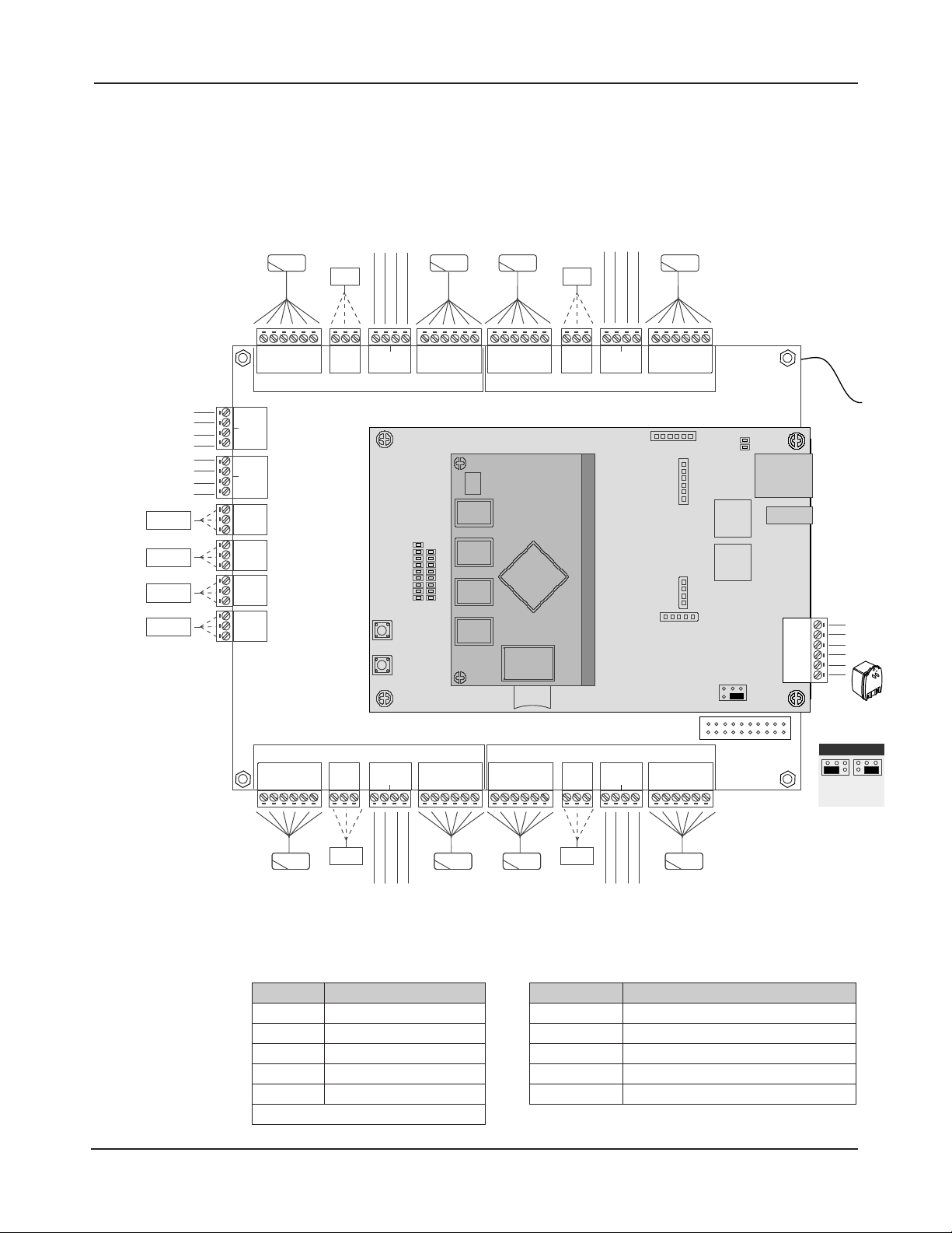
Control Panel Components
e following illustration shows the eMerge control panel wiring and components.
Figure 2.1. eMerge Board Layout
Table 2.1: LED Indicators Table 2.2: Default I/O States
LED Condition
DL17 Red On = Power On Bottom Board
DL9 Red On = Power On Middle Board
DL1 Blue On = System is Rebooted
DL1 to DL16 Blue On = System is Booting
DL19, DL 18 Blue Blink = Network Connection
NOTE: Boot up time is approx. 60 secs.
Attribute Default State
Door Status Inputs
REX Inputs Normally Open, Momentary, Unsupervised
Auxiliary Inputs Normally Open, Unsupervised
Door Lock Outputs Not Energized, Single Pulse, 3 Second Unlock Time
Aux Outputs Not Energized, Single Pulse, 3 Seconds On
Normally Open, Unsupervised, 8 Sec. Held Open Time
www.linearcorp.com 6 eMerge Essential Installation Manual
Page 7
3.0 Installing the Control Panel
+12V
LEDD0D1
GND
INPUT
GND
INPUT
GND
+12V
LEDD0D1
GNDNCC
NO
+12V
LEDD0D1
GND
INPUT
GND
INPUT
GND
+12V
LEDD0D1
GNDNCC
NO
AUX IN 2
GND
AUX IN 1
GND
AUX IN 4
GND
AUX IN 3
GND
NC
C
NO
NC
C
NO
AUX
RLY 4
AUX
RLY 3
NC
C
NO
NC
C
NO
+12V
LED
D0D1GND
+12V
LED
D0D1GND
INPUT
GND
INPUT
GNDNCC
NO
+12V
LED
D0D1GND
+12V
LEDD0D1
GND
INPUT
GND
INPUT
GND
NCCNO
DOOR 1DOOR 2
DOOR 3DOOR 4
ETHERNET
TMP -
TMP +
FLT -
FLT +
GND
12VDC
AUX
RLY 2
AUX
RLY 1
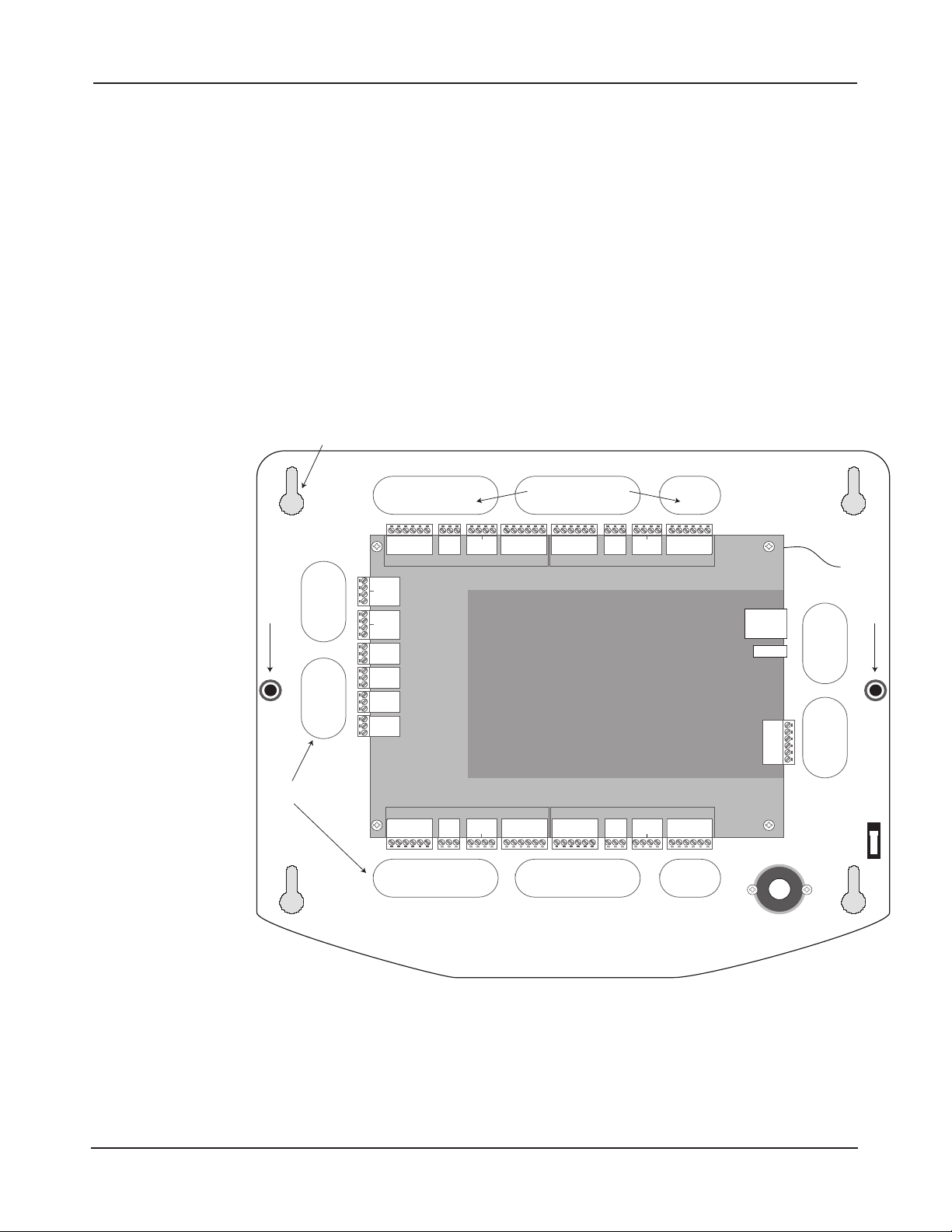
Enclosure Knockouts
Cover Screw
Cover Screw
Enclosure Knockouts
Mounting Hole
Cover
Tamper
EARTH
GROUND
LEAD
Note: This device com
plies with Part 15 of the
FCC Rules. Operation is
subject to the following
two conditions: (1) this
device may not cause
harmful interference,
and (2) this device must
accept any interference
received, including interference that may cause
undesired operation.
Note: Choose a centrally
located, clean and dry
area near an AC power
source. Avoid mounting
the panel within 6 feet
of any equipment that
generates electrical
interference.
Mounting the eMerge Essential Panel
e eMerge Essential housing is designed to accommodate the necessary wiring connections for
-
most installations. Knock-outs are provided at the back-plate of the housing. e enclosure should
be mounted in a secure location within normal temperature and humidity levels.
Installing the Panel
1. Run all necessary wires to the panel location.
2. Remove the enclosure’s cover by removing the two screws in the front of the housing.
3. Level the enclosure on a sturdy wall. Mark the mounting holes with a pencil.
4. Partially insert screws into the top two mounting holes and hang the enclosure on the screws.
5. Pull all wires through the knock-out holes in the enclosure. Label each wire according to its use.
6. Recheck for levelness, insert the two lower screws, and tighten all four mounting screws.
Caution: This equipment
includes electronic components that are highly
sensitive to static electric
ity. Please discharge by
touching a ground before
installing or handling this
equipment.
-
Figure 3.1. eMerge Essential Enclosure
www.linearcorp.com 7 eMerge Essential Installation Manual
Page 8

Mounting the eMerge Essential Plus Panel
DOOR 1DOOR 2
DOOR 3DOOR 4
Tie wrap holders
Mounting holes
Cabinet knockouts
Power Supervision
Module
Cover Tamper
e eMerge Essential Plus enclosure is designed to accommodate two 12VDC 7Ah backup batter-
ies and the necessary wiring connections for most installations. Conduit knock-outs are provided
on all sides of the enclosure. e enclosure should be mounted in a secure location within normal
temperature levels. A minimum of 12 inches of space around all sides of the enclosure is recommended.
Installing the eMerge Essential Plus
Note: Choose a centrally
located, clean and dry
area near an AC power
source. Avoid mounting
the panel within 6 feet
of any equipment that
generates electrical
interference.
Caution: This equipment
includes electronic com
ponents that are highly
sensitive to static electric
ity. Please discharge by
touching a ground before
installing or handling this
equipment.
-
-
1. Run all necessary wires to the panel location.
2. Remove the enclosure’s cover by removing the front of the housing.
3. Remove the metal cabinet knock-outs required for wire entry.
4. Level the enclosure on a sturdy wall. Mark the mounting holes with a pencil. (e cabinet
can be vertically or horizontally mounted depending on space requirements.)
5. Partially insert screws into the top two mounting holes and hang the enclosure on the screws.
6. Pull all wires through the knock-out holes in the enclosure. Label each wire according to its use.
7. Recheck for levelness, insert the two lower screws, and tighten all four mounting screws.
Figure 3.2. eMerge Essential Plus Enclosure
www.linearcorp.com 8 eMerge Essential Installation Manual
Page 9

4.0 System Power
TMP TMP +
FLT FLT +
GND
12VDC
12VDC Earth GND
GND
1 2 3
+12VDC PIP
(100-240VAC)
12VDC Earth GND
GND
1 2 3 4
+12VDC PIP
P/N PIP-12V60W
EARTH
GROUND
LEAD
e eMerge Essential is powered using a 12VDC / 5A plug-in-power supply (Linear P/N
Note: The eMerge Essential housing will not
accommodate a backup
battery. If using a backup
battery, a separate housing must be installed.
PIP-12VUR, not included). For UL listed installations, please use Linear P/N PIP-12V60W.
e control panel may also be powered using an optional Power over Ethernet (PoE) injector
(requires Linear PoE module, P/N 620-100159).
eMerge Essential Power Connection
Power Supply Connection
Caution: Improper power
wiring will damage the
fuse and void the war
-
ranty.
Note: Power should only
be applied to the system
when all connections are
secured and tested.
Cable Specications for
PIP: 14 AWG Belden (2
conductor) or equivalent.
Maximum distance: 10
feet (3 meters).
1. Connect terminal 1 from the plug-in-power supply (PIP) to pin 1 (+12VDC) on the panel.
2. Connect terminal 3 from the PIP to pin 2 (GND) on the panel.
3. Connect terminal 2 to the green earth ground lead provided in the enclosure.
4. Plug the PIP into a dedicated receptacle that is not controlled by a switch.
5. e PWR LED on the panel will illuminate to indicate that power is present.
Figure 4.1. Power Connection
www.linearcorp.com 9 eMerge Essential Installation Manual
Page 10

Power Fault Connection
PIN 6
PIN 5
PIN 4
PIN 3
PIN 2
PIN 1
EMERGE ESSENTIAL CONTROL PANEL
6-pin terminal block
+12V
LED
Buzzer
D0
Top Mounting Hole
e controller is equipped with a power fault input that can be utilized as follows:
1. Determine whether your power fault input device uses a normally closed or normally open
conguration. Please refer to instructions provided by the manufacturer.
2. Connect the power fault input device to PIN 3 and PIN 4 on the terminal strip.
3. Apply power and verify that the power fault input device is functioning properly.
TMP TMP +
FLT FLT +
GND
12VDC
Power Fault Input
Figure 4.2. eMerge Essential Power Fault Connection
www.linearcorp.com 10 eMerge Essential Installation Manual
Page 11

TMP TMP +
FLT FLT +
GND
12VDC
To 12VDC PIP
Fault Output
Tamper Switch
12VDC Earth GND
GND
1 2 3 4
+12VDC PIP
P/N PIP-12V60W
Earth
Ground
Lead
Note: The system will not
power up using the back
up battery. The 12VDC
PIP (P/N PIP-12V60W)
or PoE (P/N 620-100159)
must be present to power
up the system.
Cable Specications for
PIP: 14 AWG Belden (2
conductor) or equivalent.
Maximum distance: 10
feet (3 meters).
-
eMerge Essential Plus Power Connection
e eMerge Essential Plus includes a factory installed power supervision module as shown in
Figure 4.3.
Power Supply Connection
1. Connect the +12VDC PIP (Linear P/N PIP-12V60W ) to the red and black leads of the
power supervision module.
2. Connect terminal 2 or 3 of the PIP to the green earth ground lead provided in the enclosure.
3. Plug the PIP into a dedicated receptacle that is not controlled by a switch.
4. e PWR LED on the panel will illuminate to indicate that power is present.
5. Place the 12VDC backup battery in the cabinet.
6. Connect the red and black leads to the battery.
Figure 4.3. eMerge Essential Plus Power Connection
Battery Connection
Note: The SD card slot
(shown earlier in Figure
2.1) will backup panel
memory in the absence of
power or backup battery.
e eMerge Essential Plus provides charging and space for up to two 12VDC/7Ah sealed lead-acid
batteries. e battery provides standby power when the primary power source is lost. e control
panel will utilize backup battery until the battery reaches 11VDC at which point the entire
system shuts down.
Note: It is recommended
to replace the system bat
tery every 2 to 3 years.
www.linearcorp.com 11 eMerge Essential Installation Manual
-
Page 12
To determine standby battery time:
PIN 6
PIN 5
PIN 4
PIN 3
PIN 2
PIN 1
EMERGE ESSENTIAL CONTROL PANEL
6-pin terminal block
+12V
LED
Buzzer
D0
Top Mounting Hole
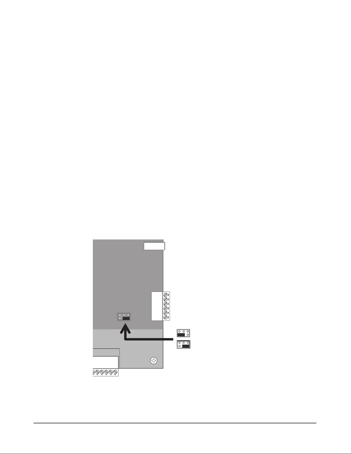
JP1
EXTERNAL 12VDC
POE
(Default)
Note: The eMerge Essential controller board
consumes 200 mA of current at 12VDC (2.4W).
Note: The Linear PoE
module (P/N 620-100159)
must be installed in order
to use a PoE injector (P/N
POE-PLUS).
1. Determine the total standby load of the system by adding the maximum and standby current
draw of the devices connected to the panel. For example, if the system consists of the control
panel (200 mA) and one 75 mA reader the total standby load is 275 mA (200 mA+ 75 mA).
2. Divide the total standby load by 1000 to convert it to amps. For example, 275 / 1000 = .275.
3. Divide the amp-hour rating of the battery by the total standby load to determine the standby
time for the system. For example, 7.0 / .275 = 25.5 hours standby time using a 7 AH battery
with a system that consists of the control panel and one 75 mA reader.
Power Fault
If AC power loss is detected, the power supervision module will automatically switch to the
backup battery and activate the fault input. e fault input can be congured via programming to
activate a condition (dialer, etc.). e transaction will be logged in the history of the controller.
Tamper Protection
A tamper switch is mounted inside the enclosure and is pre-wired to the tamper input on the
terminal strip. If the eMerge Essential cover is removed for any reason the tamper switch will
activate, triggering a condition that can be linked to an event action in programming (e.g., send
an e-mail or generate an output).
PoE Connection
e eMerge Essential can be powered using Power over Ethernet (PoE), which is a method for
providing power via Ethernet cabling. To place the controller in PoE mode, move the Power
Input Jumper to the left position as illustrated in Figure 4.4.
A Power over Ethernet installation must consist of a high-power 30W PoE injector (P/N POEPLUS) and the Liner E3-POE module (P/N 620-100159). Refer to the PoE module’s installation guide for specic installation information.
Figure 4.4. Power Input Jumper
www.linearcorp.com 12 eMerge Essential Installation Manual
Page 13

5.0 Inputs and Outputs
System Inputs
e system has the capability of monitoring up to 4 door status inputs, 4 request to exit (REX)
inputs, 4 auxiliary general purpose inputs and 2 digital inputs (reserved for future release).
All inputs are assigned default features that can be congured as needed. e following table
shows the default states for each of the inputs:
Table 5.1: Default Input States
Input Default State
Door Status Inputs Normally Open, Unsupervised, 8 Second Held Open Time
REX Inputs Normally Open, Momentary, Unsupervised
Auxiliary Inputs Normally Open, Unsupervised
Door Status Input
e door status input monitors whether the door is in an open or closed state. A door status
switch (typically a magnetic reed switch) will change states when the door is opened or closed.
e door status input does not require any programming to enable. Simply connect a magnetic
reed switch to the appropriate door input as shown in the control panel illustration, Figure 2.1.
Request To Exit
e Request to Exit (REX) input is a momentary input closure that activates the door output relay for
the same amount of time as a valid card swipe or keypad entry. REX devices can include a press-toexit switch on the inside of a door or a passive infared detector (motion detector), which allows convenient egress. e REX input does not require any programming. Simply connect a normally open,
momentary input device to the REX inputs as shown in the control panel illustration, Figure 2.1.
Auxiliary Inputs
e auxiliary inputs are general purpose inputs that can be used with a variety of input devices
including CO2 detectors, alarm system integration, etc. ese inputs can be congured via programming to trigger a dened action such as to activate an output.
www.linearcorp.com 13 eMerge Essential Installation Manual
Page 14

Normally Open
Normally Closed
Normally Open
Normally Closed
SUPERVISED UNSUPERVISED
Resistor Value = 1k Ohm
PIN 6
PIN 5
PIN 4
PIN 3
PIN 2
PIN 1
EMERGE ESSENTIAL CONTROL PANEL
6-pin terminal block
+12V
LED
Buzzer
D0
D1
Cable Specications:
22 AWG Belden or
equivalent. Maximum
distance: 2000 feet.
Wiring the Inputs
All inputs may be congured for normally open or normally closed contacts with supervision or
non-supervision. Use standard 1k ohm resistors for supervision. Refer to Figure 5.1 for the acceptable wiring congurations.
Figure 5.1. Input Circuit Congurations
Tamper Protection (Emerge Essential)
A tamper switch is mounted inside the enclosure for connection to pin 5 and pin 6 on the terminal strip.
If the eMerge Essential cover is removed for any reason the tamper switch will activate, triggering a condition that can be linked to an event action in programming (e.g., send an e-mail or generate an output).
TMP TMP +
FLT FLT +
GND
12VDC
Factory
Installed
Tamper
Figure 5.2. eMerge Essential Tamper Input Wiring
www.linearcorp.com 14 eMerge Essential Installation Manual
Page 15

System Outputs
e eMerge Essential provides up to 4 door lock relays and 4 auxiliary output relays that may be
activated in response to reader activity, time schedules or input conditions. All relays are Form-C
SPDT and provide non-powered dry contacts rated for 1A.
Output Defaults
All outputs are assigned default features that can be congured as needed. e following table
shows the default states for each of the outputs:
Table 5.2: Default Output States
Output Default State Default Response
Door Lock Outputs 1-4 Not Energized, Single Pulse
Aux Outputs 1-4 Not Energized, Single Pulse No default response. Must be configured via programming.
3 second unlock time in response to corresponding reader
activity (Reader 1 activates door 1 lock relay)
Wiring Requirements
e cable must be the proper gauge for the current load and should not be bundled with other
wiring. Refer to the Table 5.3 for wiring recommendations:
Table 5.3: Recommended Wiring Requirements
Total Amps Voltage (AC or DC)
.5 A
1.00 A
2.00 A
3.00 A
12V 1500 ft 1000 ft 600 ft 375 ft 225 ft
24V 2000 ft 1200 ft 750 ft 450 ft 300 ft
12V 800 ft 500 ft 300 ft 200 ft 100 ft
24V 1000 ft 600 ft 400 ft 200 ft 150 ft
12V 400 ft 240 ft 150 ft 90 ft 60 ft
24V 480 ft 300 ft 180 ft 120 ft 70 ft
12V 260 ft 160 ft 100 ft 60 ft
24V 320 ft 200 ft 120 ft
Wiring Gauges and Distance
14 16 18 20 22
www.linearcorp.com 15 eMerge Essential Installation Manual
Page 16
+12V
LED
Buzzer
D0
D1
GND
INPUT
GND
INPUT
GND
NC
C
NO
NC
C
NO
CONTROL PANEL’S
DOOR LOCK RELAY
DOOR 3DOOR 4
ETHERNET
TMP -
TMP +
FLT -
FLT +
GND
+12VDC
DC POWER
SUPPLY
+
-
DIODE 1N4933
OR
EQUIVALENT
DC DOOR STRIKE
+
-
+12V
LED
Buzzer
D0
D1
GND
INPUT
GND
INPUT
GND
NC
C
NO
NC
C
NO
DOOR 3DOOR 4
ETHERNET
TMP -
TMP +
FLT -
FLT +
GND
+12VDC
DC POWER
SUPPLY
+
-
DIODE 1N4933
OR
EQUIVALENT
DC DOOR STRIKE
+
-
CONTROL PANEL’S
DOOR LOCK RELAY
+12V
LED
Buzzer
D0
D1
GND
INPUT
GND
INPUT
GND
NC
C
NO
NC
C
NO
CONTROL PANEL’S
DOOR LOCK RELAY
DOOR 3DOOR 4
ETHERNET
TMP -
TMP +
FLT -
FLT +
GND
+12VDC
AC POWER
SUPPLY
MOV SNR-D56K2
OR
EQUIVALENT
AC DOOR STRIKE
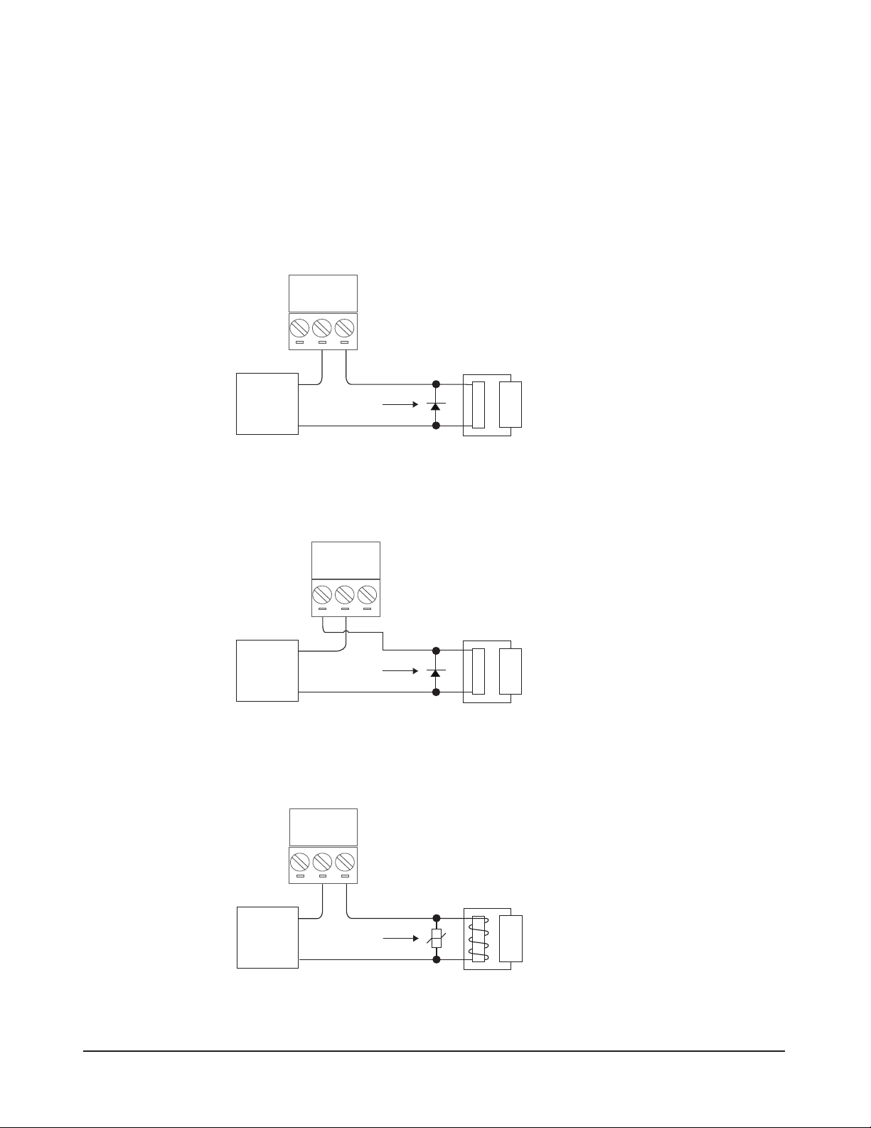
Door Lock Outputs
e door lock outputs for doors 1 through 4 can be congured to operate in normally energized
(fail-secure) or normally not-energized (fail-safe) modes.
Caution: The diode or
MOV must be installed
as shown in the illustrations. Failure to install
these protection devices
may damage the control
board.
Wiring the Door Locks
Connect locking devices to the door relay as shown in Figures 5.3 through 5.5. Refer to the door
strike specications to determine the appropriate voltage and conguration. WARNING: Do not
use the control panel’s power output for the locking device. An auxiliary power supply must be used.
Figure 5.3. Fail Safe DC Door Strike
Figure 5.4. Fail Secure DC Door Strike
Figure 5.5. Fail Safe AC Door Strike
www.linearcorp.com 16 eMerge Essential Installation Manual
Page 17
Door Lock Operation
READER
+12V
LED
D0
D1
GND
RED BRN GRN WHT BLK
1. Present a valid card/PIN to a reader/keypad.
2. e controller will activate the door relay output associated with the particular reader (e.g.,
3. e relay output is energized for a default time of 3 seconds.
4. As the user enters through the door, the door status input will change from closed to open.
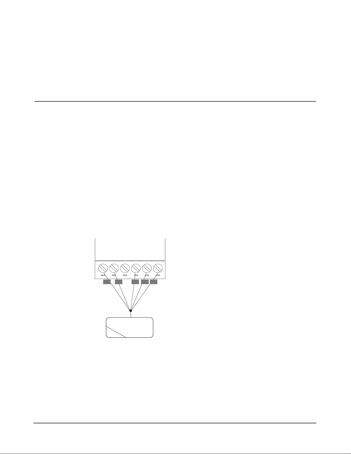
6.0 Readers
Wiring the Readers
e control panel can accept up to 8 readers or keypads. Each reader port on the panel supports a
12VDC reader with Wiegand output format. Readers can be installed as primary (entry) readers
for each of the 4 doors as well as optional secondary (exit) readers.
e maximum power available for each reader is 750 mA @ 12 VDC. Determine the reader’s
power consumption by referring to the documentation included with the reader.
Wiring Readers
1. Remove power from the control panel.
2. Pull the reader wiring through a knock-out in the panel’s enclosure.
Caution: Improper power
wiring will damage the
fuse and void the warranty.
3. Connect the color-coded wires from the reader’s wiring harness to the appropriate location of
4. Remove excess shield to ensure that it is not exposed. An exposed shield can cause interference.
reader 1 will activate door lock relay 1).
terminal strip as shown in Figure 6.1.
Tape o any exposed shield with electrical tape.
Cable Specications:
Twisted, shielded 22
AWG (250 ft.) or 18 AWG
(500 ft.) Belden #9535 (5
conductor) or equivalent.
Please follow manufactur
ers installation requirements.
www.linearcorp.com 17 eMerge Essential Installation Manual
-
Figure 6.1. Reader Wiring
Page 18

7.0 Network Connection
e eMerge Essential must be located in a trusted network environment where a protected net-
Caution: The system is
exposed to potential risks
if installed on a network
without proper security
precautions. Consult the
appropriate on-site IT
administrator.
Note: If a DHCP
server is present, IP
Addresses are dynami
cally assigned. A static
IP address is required for
the controller because
a DHCP Server may
assign a new IP Address
resulting in loss of communication.
work security system (rewall, etc.) is installed and maintained. Before you congure the controller please obtain the following information from your network administrator:
♦ IP address (if applicable)
♦ Subnet Mask
♦ Gateway
♦ DNS 1 and 2
Preparing for the Network
To allow for the eMerge Essential to be recognized on the local network, it is necessary to change
the controller’s IP address as follows:
1. Connect your programming computer directly to the Ethernet port of the control panel as shown
-
in Figure 7.1. (You may also connect the computer and control panel to an Ethernet Switch.)
LAN LED
ETHERNET
Figure 7.1. Connecting to the Control Panel
2. Assign a static IP address of 192.168.0.149 to the computer. (For instructions on how to
change the static IP address of a Windows computer, please visit: http://technet.microsoft.
com/en-us/library/710457).
3. After assigning the static IP address,
open a web browser and
enter the IP address of the
controller (Default = 192.168.0.250).
4. e controller presents the eMerge page as shown in Figure 7.2. To log on, enter the default
user ID and password (admin/admin).
Figure 7.2. Web Server Login Page
www.linearcorp.com 18 eMerge Essential Installation Manual
Page 19

3. Browse to the Network Conguration page as shown in Figure 7.3. Enter the static IP address, Subnet Mask, Gateway and DNS server so that it matches the requirements of the
local network. (Refer to the User Manual for complete programming information.)
Figure 7.3. Network Settings Page
4. Click Save & Reboot and the system will reboot.
5. Disconnect the programming computer from the control panel. e eMerge Essential is now
ready for the local network.
Connecting to the Network
1. Pull an Ethernet cable through the opening in the enclosure nearest the Ethernet port.
2. Plug the RJ-45 connector into the Ethernet port on the controller.
3. Connect to the local area network (LAN) as shown in Figure 7.4.
Cable specication:
CAT 5 or better with an
RJ-45 connector wired
straight through to a
network hub, switch or
router.
Internet
EMERGE
LAN
Router
Client Computer
Figure 7.4. Connecting the eMerge to a LAN
4. If the network connection is functioning properly, the LAN LEDs on the control panel will
illuminate as shown in Figure 7.5. e local computers will then be able to access the system
by entering the IP address of the controller.
www.linearcorp.com 19 eMerge Essential Installation Manual
Page 20

ETHERNET
LAN LEDS
DL19
DL18
Figure 7.5. eMerge LAN LEDs
Programming the System
e eMerge Essential provides the ability to access and manage the system from a web browser on any
local or remote computer. Refer to the User Programming Guide (P/N 620-100240) for programming
and conguration instructions.
8.0 Troubleshooting
Table 8.1: Troubleshooting the System
Problem Solution
The control panel does not power up.
The control panel powers up but does not
respond to card readers or inputs.
No network communication exists with
the control panel.
How to reboot the system? • Hardware Reboot system: Momentarily press switch S2 on middle board (near bank of 16 LED’s).
How to clear the memory of the system
and restore factory defaults?
For further troubleshooting assistance, please visit the following online resources:
• Check setting of JP1 on middle board (near input power connector) to ensure that the
jumper is in the appropriate position for your desired power source.
• Measure input power for +12VDC
• If RED LED’s are off, then input fuse may be blown. This fuse is not field-replaceable.
• Measure power at reader connectors. If no voltage is present, then reader fuse may be blown.
• Bring reader and/or input and connect directly at the panel. If it works at the panel, the
wire run may be faulty.
• If LAN LED’s are off or solid, then no physical network connection exists. Check network cabling.
• Verify the Subnet Mask, Gateway, DNS and IP address as provided by the network admin.
• Press and Hold switch S1 for full 20 seconds on middle board (near bank of 16 LED’s).
• You may also reboot and factory default the system using the GUI software.
NOTE: If factory default, will need to re-enter license key and configure system.
♦ http://www.linearcorp.com/faq/
Linear Technical Support:
♦ Tel: (800) 421-1587;
♦ Hours: 5:00 AM to 4:30 PM Pacic Time, M-F
www.linearcorp.com 20 eMerge Essential Installation Manual
Copyright © 2013 Linear LLC 620-100239 C
 Loading...