

Page 1

eMerge™ Browser Managed Security Platform
Installation Guide
International Electronics, Inc.
427 Turnpike St.
Canton, MA 02021
www.ieib.com
Document # : 6047001-UL Rev 3.0
.
Page 2

UL Listing
The IEI eMerge™ is UL 294 Listed. For UL applications Inputs and Outputs may be used for
Access Control systems only. Inputs and Outputs are to be installed in protected premises.
FCC Notice
The IEI eMerge complies with the limits for a Class A digital device, pursuant to Part 15 of
the FCC Rules. These limits are designed to provide reasonable protection against harmful
interference when the device is operated in a commercial environment. This equipment
generates and can radiate radio frequency energy and, if not installed and used in
accordance with the instruction manual, may cause harmful interference to radio
communications. Operation of this equipment in a residential area is likely to cause harmful
interference in which case the user will be required to correct the interference at their
expense. The IEI eMerge complies with FCC Class B operation if a full loop ferrite bead (e.g.
Fair Rite PN: 0443164151 or equivalent) is used on the external Ethernet cable.
CE Compliance
Compliance with CE Standards EN61000-4-3 and EN50130 requires that all wiring entering
the IEI eMerge be run through properly grounded metal conduit. Compliance with CE
Standard 61000-4-5 requires the use of a shielded Ethernet cable for any cable longer than
30 meters connecting to a local area network.
Disclaimer
The International Electronics, Inc. provides this publication “as is,” without warranty of any
kind, either expressed or implied. The International Electronics, Inc. shall not be liable for
errors contained herein or for incidental or consequential damages in connection with the
furnishing, performance, or use of this guide.
Copyright
© International Electronics, Inc 2004-2005. All rights reserved.
This guide is protected by copyright and all rights are reserved by International Electronics,
Inc. It may not, in whole or in part, except insofar as herein directed, be copied, photocopied,
reproduced, translated or reduced to any electronic medium or machine-readable form
without prior written consent of International Electronics, Inc..
IEI eMerge™ is a trademark of International Electronics, Inc.
Model Numbers
This manual applies to IEI models eMerge and eMergeEXN.
Document #: 6047001-UL, Rev 3.0
2
Page 3

Table of Contents
PREPARING TO INSTALL......................................................................................... 5
SYSTEM COMPONENTS ...........................................................................................................................5
TOPOLOGY CONSIDERATIONS .................................................................................................................6
NETWORK REQUIREMENTS ..................................................................................................................... 8
BROWSER REQUIREMENTS ..................................................................................................................... 9
THIRD PARTY DEVICE REQUIREMENTS .................................................................................................... 9
ENVIRONMENTAL REQUIREMENTS ...........................................................................................................9
INSTALLATION OVERVIEW CHECKLIST ...................................................................................................10
INSTALLING THE IEI EMERGE .............................................................................. 11
INSTALLING ADDITIONAL MODULES .......................................................................................................11
INSTALLING THE CABINET TAMPER SWITCH ........................................................................................... 13
INSTALLING THE I-BUTTON LICENSE ...................................................................................................... 14
MOUNTING THE IEI EMERGE CABINET ................................................................................................... 15
WIRING A BATTERY .............................................................................................................................. 16
WIRING POWER TO THE IEI EMERGE ..................................................................................................... 17
CONNECTING READERS ........................................................................................................................19
CONNECTING INPUTS ............................................................................................................................22
CONNECTING OUTPUTS ........................................................................................................................ 26
CONNECTING ELEVATOR RELAY OUTPUTS ............................................................................................28
CONNECTING TO THE NETWORK AND SETTING INITIAL VALUES .................. 29
SETTING INITIALIZATION VALUES........................................................................................................... 30
INFORMATION FOR NETWORK ADMINISTRATORS ....................................................................................36
INITIAL SYSTEM SETUP CHECKLISTS................................................................. 38
SYSTEM ADMINISTRATION AND MONITORING ......................................................................................... 41
TESTING AND TROUBLESHOOTING .................................................................... 42
THE CONTROLLER/NODE MODULE ........................................................................................................42
IEI EMERGE CABINET DOOR LED ......................................................................................................... 46
ACCESS MODULE AND LEDS................................................................................................................ 47
INPUT AND OUTPUT MODULE LEDS ......................................................................................................47
IEI EMERGE POWER SUPPLY LEDS ......................................................................................................48
TESTING PROCEDURE........................................................................................................................... 49
REMOVING MODULES FOR MAINTENANCE .............................................................................................. 49
APPENDICES........................................................................................................... 50
A. HARDWARE AND SOFTWARE SPECIFICATIONS ...................................................................................50
B. SUPPORT INFO................................................................................................................................. 53
C. LEGAL NOTICES AND LICENSE AGREEMENTS.................................................................................... 54
D. INSTALLATION DESCRIPTION FORMS ................................................................................................. 59
INDEX....................................................................................................................... 64
Document #: 6047001-UL, Rev 3.0
3
Page 4

Note to Installers
Install according to National Electrical Code (ANSI/NFPA70) and local codes use only UL
Listed equipment.
CAUTION!!!
OBSERVE STATIC ELECTRICITY PRECAUTIONS WHEN HANDLING AND INSTALLING IEI
COMPONENTS. THESE COMPONENTS CAN BE DAMAGED BY STATIC DISCHARGE.
Document #: 6047001-UL, Rev 3.0
4
Page 5

Preparing to Install
System Components
The basic IEI eMerge™ system consists of either an eMerge Network Controller (eNC) with an
Access Control Module (ACM) or an eMerge Network Node (eNN, also referred to as an
Expansion Node or eMergeEXN) with an Access Control Module (ACM). Please note the Network
Controller and the Network Node use the same printed circuit board (the Network Controller
includes all the components used on the Network Node), and is sometimes referred to as a
combination board. In addition, you can add any one of the three application extension modules
shown below.
The Controller/Node module mounts in the top slot of the IEI eMerge cabinet.
The Network Controller includes the IEI eMerge Application, the IEI Security Activity Database, a
Linux® operating system and other software components. No PC server is required. For
diagrams of the Controller/Node boards see the “Testing and Troubleshooting” section.
Each Network Node handles communications to and from the Controller and the power
distribution to other application modules in the eMerge. Each node supports up to seven eMerge
Application Extension Modules in any combination.
Up to 32 eMerge Network Nodes may be connected to a network and controlled by a single
Network Controller. The IEI eMerge is a stand-alone system that does not require a PC to
operate. A PC is required only for system setup, programming, and monitoring.
For UL applications the IEI eMerge™ is a stand-alone system and communication to a monitoring
station was not evaluated by UL.
There are 3 types of Application Extension modules:
1. Access module: 2 Weigand reader interfaces, 4 supervised inputs, and 4 relay outputs.
2. Input module: 8 supervised inputs.
3. Output module: 8 relay outputs.
All eMerge Application Extension modules receive power and communications from the Node via
the ribbon cable bus. The Node in turn communicates with the Network Controller over the IP
network internally on the board.
Power Requirements
IEI eMerge systems must be AC powered using the wall socket transformer provided. The
transformer must be powered with 120V AC at 50-60 Hz. Power should come from a
separate circuit
inside the eMerge cabinet.
Transformer specifications :
• Revere Industries. Class 2 Transformer
• Model: RT-G2450SL/M
• Input: 120VAC 60Hz
• Output: 24VAC 50VA
The IEI eMerge includes a DC power supply. The eMerge power supply provides 12V DC at
2.5 amps. The total system current, including all modules, readers, and battery charging
current must not exceed 2.5 A.
with an isolated ground and must be wired to the power supply mounted
Document #: 6047001-UL, Rev 3.0
5
Page 6

Note: Do not run wires from the output of the eMerge power supply outside the eMerge
enclosure.
Reader Power Available from the IEI eMerge
Access Control Module Reader Electrical Rating: 12VDC, 400mA (maximum)
The ACM has two reader ports and the 400mA maximum rating includes both ports. This
means you can draw 400mA out of a single reader port or divide the total current between
the two ports. For example, you can connect a 100mA reader to port one and a 300mA
reader to port two.
You can connect multiple readers to each reader port on the ACM, as long as the total
current between both ports does not exceed 400mA. If your reader(s) require more current,
or a different voltage, then a separate UL Listed, power-limited access control power supply
is required. Refer to the reader manufacturer documentation for power specifications.
Please note, the total system current, including all modules, readers, and battery charging
current must not exceed 2.5 A.
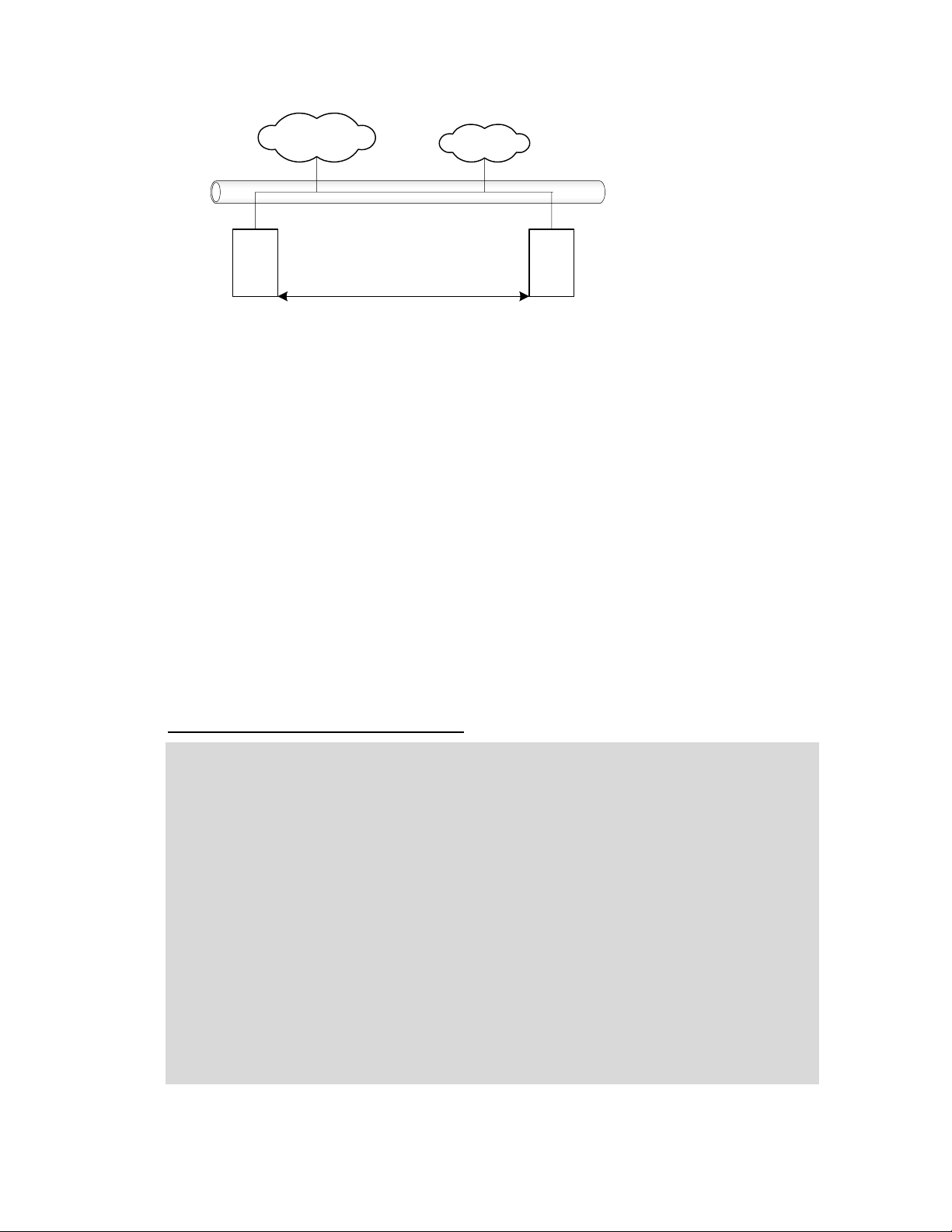
Topology Considerations
Issues to consider when selecting a topology for the eMerge installation include simplicity,
security, wiring requirements, bandwidth requirements, site distances, current network topology,
and the number of security system resources to be wired.
Internet
Corporate LAN
Users and
servers
The simplest topology for IEI eMerge installation.
The simplest topology, shown in the diagram above, will be the most common case for small
systems. All users and network resources share the same LAN. This topology is somewhat less
secure than the following example using a router.
IEI eMerge
Document #: 6047001-UL, Rev 3.0
6
Page 7

Internet
Corporate LAN
Users and
servers
Security LAN
IEI eMerge
A router with a subnet for IEI eMerge installation.
The diagram above shows a somewhat more complicated but inherently more secure topology. In
this case an inexpensive router is used to create a subnet for the security system. The
advantages here are increased network security and decreased bandwidth requirements because
the corporate LAN does not directly carry traffic between the Nodes and the Controller. The
disadvantages include potentially increased wiring, complexity, and router configuration.
Router
Node Installation Considerations
A node is an IEI eMerge without the Network Controller on the combination board. Site
layout and distance considerations play a role in deciding where and how many nodes may
be required or desirable. For example:
• Reader wiring that exceeds 500 feet (152 meters) will require an additional node to
reduce the wire lengths to less than that maximum.
• Input or output wiring that exceeds 2000 feet (610 meters), while uncommon, will
require an additional node to reduce the wire lengths to less than that maximum.
• Need for system resources on another floor of a building may make an additional
node desirable to simplify wiring.
• Need for system resources at opposite ends of a building, or in two separate
buildings on one site, may make an additional node(s) desirable to simplify wiring.
Document #: 6047001-UL, Rev 3.0
7
Page 8
Users and
servers
Internet
Corporate LAN
eMerge
Network Controller
Significant distance?
Site layout or distances may make a node installation desirable.
In the diagram above it may be possible to install one IEI eMerge and wire all the system
resources to it, but that may require running numerous wire lengths over considerable
distances. It may be faster, easier, and less expensive to place an eMerge Network Node at
one end or floor of the site and wire all local system resources to it. Communication to the
Controller at the remote location can be handled by the local area network wiring already in
place.
Note that while a minimum system co-locates the Controller and the Node in the same IEI
eMerge cabinet, it is not necessary to do so.
Note: Evaluated by UL for stand-alone operation only.
Separate floors?
eMerge
Network Node
Network Requirements
The eMerge is designed to work with Ethernet networks using TCP/IP. While it will operate on
10baseT networks, 100baseT is preferred.
Get the following information from the network administrator.
Required Network Information Checklist
DNS (Domain Name Server) IP address(es).
Gateway IP address, if any.
Subnet mask and IP addresses for the eNC and nodes.
Email relay server address or name.
Email address name for the eNC and setup on the email server to accept mail from the
eNC for relay.
Domain account name and password for a server providing network attached storage
(NAS).
Network attached storage server name in UNC (Universal Naming Convention) format:
\\domain name\\machine name\\share name.
Network time server name(s) if the network has no Internet access. Pool.ntp.org is
specified by default.
Document #: 6047001-UL, Rev 3.0
8
Page 9

Browser Requirements
The IEI Security Application is designed to work with Internet Explorer Version 6.0 or higher, and
Mozilla Firefox version 1.0.
Third Party Device Requirements
NOTE: Check the IEI web site (www.ieib.com) for an updated list of supported devices, and
software updates.
Readers
The IEI eMerge Access control module supports card readers that use the Wiegand Reader
Interface. UL evaluated the HID ProxPoint proximity reader for compatibility with the eMerge
system.
Cameras
The eMerge Network Controller supports up to 16 cameras. IP video cameras may be
connected directly to the network and driven by the Controller. IEI eMerge release 2.1 works
with the following camera models:
• Panasonic NM 100
• Panasonic NS 324
• Axis 2120
• Axis 205, 206
• Vivotek
• Sony SNC-DF40N/DF40P
• Sony SNC-P1
Note: The use of cameras was not evaluated by UL.
Digital Video Recorder
IEI eMerge release 2.1 supports DVR integration and use with the following model:
• Dedicated Micros DS2
• Dedicated Micros DV-IP
Note: The use of a Digital Video Recorder was not evaluated by UL.
Environmental Requirements
• Operating temperature range: 32° F to 120° F (0° C to 49° C).
• Operating relative humidity range: Up to 85% non-condensing.
Document #: 6047001-UL, Rev 3.0
9
Page 10

Installation Overview Checklist
The following checklist presents all major steps required for the completion of an IEI eMerge
Security System installation. The installation does not have to be done in this particular order,
however, the checklist has been designed to present a logical order for the completion of all
steps.
Installation Overview Checklist
Preparation steps (page 5)
Install any required additional modules into the IEI eMerge (page 11)
Install the I-button license onto the Controller/Node module (page 14)
Mount the IEI eMerge cabinet (page 15)
Connect readers (page 189)
Connect inputs (page 221)
Connect outputs (page 25)
Connect power to the IEI eMerge (page 17)
Connect to the network (page 29)
Set IP address and other TCP configuration information (page 30)
Initial System Setup Checklist (page 37 and Online Help)
Provide to the Customer the Installation Description and Support Info pages.
CAUTION!!! OBSERVE STATIC ELECTRICITY PRECAUTIONS WHEN HANDLING AND
INSTALLING IEI EMERGE COMPONENTS. THESE COMPONENTS CAN BE DAMAGED BY
STATIC DISCHARGE.
Static Precautions Checklist
Discharge by touching a ground before handling components.
Wear a grounded wrist strap or stand on a grounded mat.
Limit movement to limit static buildup.
Document #: 6047001-UL, Rev 3.0
10
Page 11

Installing the IEI eMerge
Installing Additional Modules
The IEI eMerge has 8 slots in the aluminum chassis for installing modules. The topmost slot is
reserved for the combination Controller/Node module which handles communications and the
power distribution to the application modules in the IEI eMerge. The remaining slots can hold any
combination of Access, Input, and Output modules and are numbered 1 through 7 as in the
diagram below. Note that the slots are physical mounting points only. The electrical connection is
made through the ribbon cable.
Tamper switch
mounts
0
Controller/Node
module slot
Power Supply
1
2
3
4
5
6
7
The IEI eMerge cabinet and slot numbering.
Slot numbers
It is recommended that slots 1, 2, 3, 5, and 7 be used first. Spacing inside the eMerge will be
easier to work with. Slots 4 and 6 should be used only if more than five modules are required.
Slot and Position Numbers
Slot numbers are determined by the connector on the ribbon cable that is plugged into the
module. The ribbon cable (see diagram below) is a bus and a module’s place on the bus
determines the slot number. You will see that it is possible to place a module in physical slot
5 and yet attach ribbon cable connector 6 to the module. If this occurs the module will be in
slot 6 on the bus.
Controller/Node
connector
Connectors for slots
1 2 3 4 5 6 7
The IEI ribbon cable bus viewed from above.
Position numbers are determined by the connector position on the module itself. See the
sections below on Connecting Readers, Connecting Inputs, and Connecting Outputs.
CAUTION!!! MAKE SURE ALL POWER IS OFF BEFORE CONNECTING OR DISCONNECTING
MODULES IN THE IEI EMERGE.
Document #: 6047001-UL, Rev 3.0
11
Page 12

To install a module in the IEI eMerge:
1. Power down the eMerge. To ensure that the eMerge database is properly saved reboot
the eMerge and then power down. The reboot procedure includes saving the security
database. Select Setup : System Maintenance : Utility.
2. Thread the standoff tube provided down onto the threaded post on the chassis next to the
slot where you will insert the additional module.
3. Be sure that you are grounded and insert the additional module into the slot on the
chassis with the ribbon cable connector toward the left of the eMerge cabinet. See
diagram below.
4. Place the lock washer provided over the top of the standoff and thread the screw provided
through the flange and down into the top of the standoff and snugly down onto the lock
washer. See diagram below.
lock washer
Standoff comes
flush to flange
Board
goes down
into slot
standoff tube
5. Connect the ribbon cable from the Controller/Node module in the topmost slot to the newly
installed module. The connector is polarized. Make sure that the center bump fits into the
opening for it on the connector on the module. Press the connector firmly into place until
you hear the click of the extraction levers snapping into vertical position. You may have to
press the extraction levers into full vertical position before you will hear the click.
6. Record on an eMerge Installation Description Form (make a copy from Appendix D) the
exact slot number and module type.
Document #: 6047001-UL, Rev 3.0
12
Page 13
Installing the Cabinet Tamper Switch
The eMerge systems ship with a cabinet tamper switch, which is required for UL compliance.
To install the cabinet door tamper switch:
1. Be sure that there is no power to the eMerge system and that you are grounded.
2. Remove the tamper switch from the parts bag.
3. Set the tamper switch onto the mounting posts in the upper right corner of the cabinet.
The eMerge cabinet tamper switch.
4. Place lock washers and nuts on all three posts and finger tighten.
Tamper switch
mounts
The eMerge cabinet tamper switch mounts.
5. A 2-pin connector is pre-wired to the tamper switch. Plug this connector onto the cabinet
tamper switch connector on the Controller/Node module.
Processor
Cabinet
tamper switch
connector
The cabinet tamper switch connector on the Controller/Node module.
Document #: 6047001-UL, Rev 3.0
13
Page 14

Installing the I-button License
The eMerge systems ship with an I-button chip that is your software license. This I-button is
packed in a small zip-lock bag.
To install the I-button licensing chip:
1. Be sure that there is no power to the eMerge system and that you are grounded.
2. Remove the I-button from the zip-lock bag.
The I-button licensing chip.
3. Insert the I-button into the I-button socket on the bottom side of the Controller/Node
module.
The I-button licensing chip socket is on the underside of the Controller/Node module.
4. Be sure that the I-button is fully seated into the socket such that the retaining clips are
over the rim and holding it in place.
Document #: 6047001-UL, Rev 3.0
14
Page 15
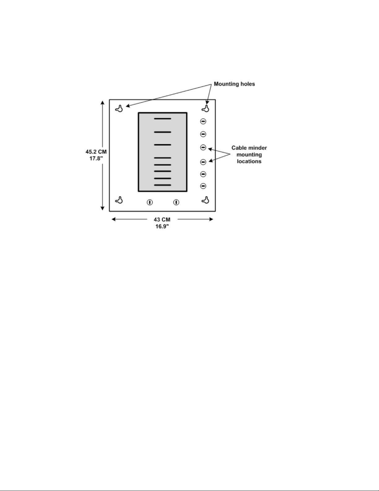
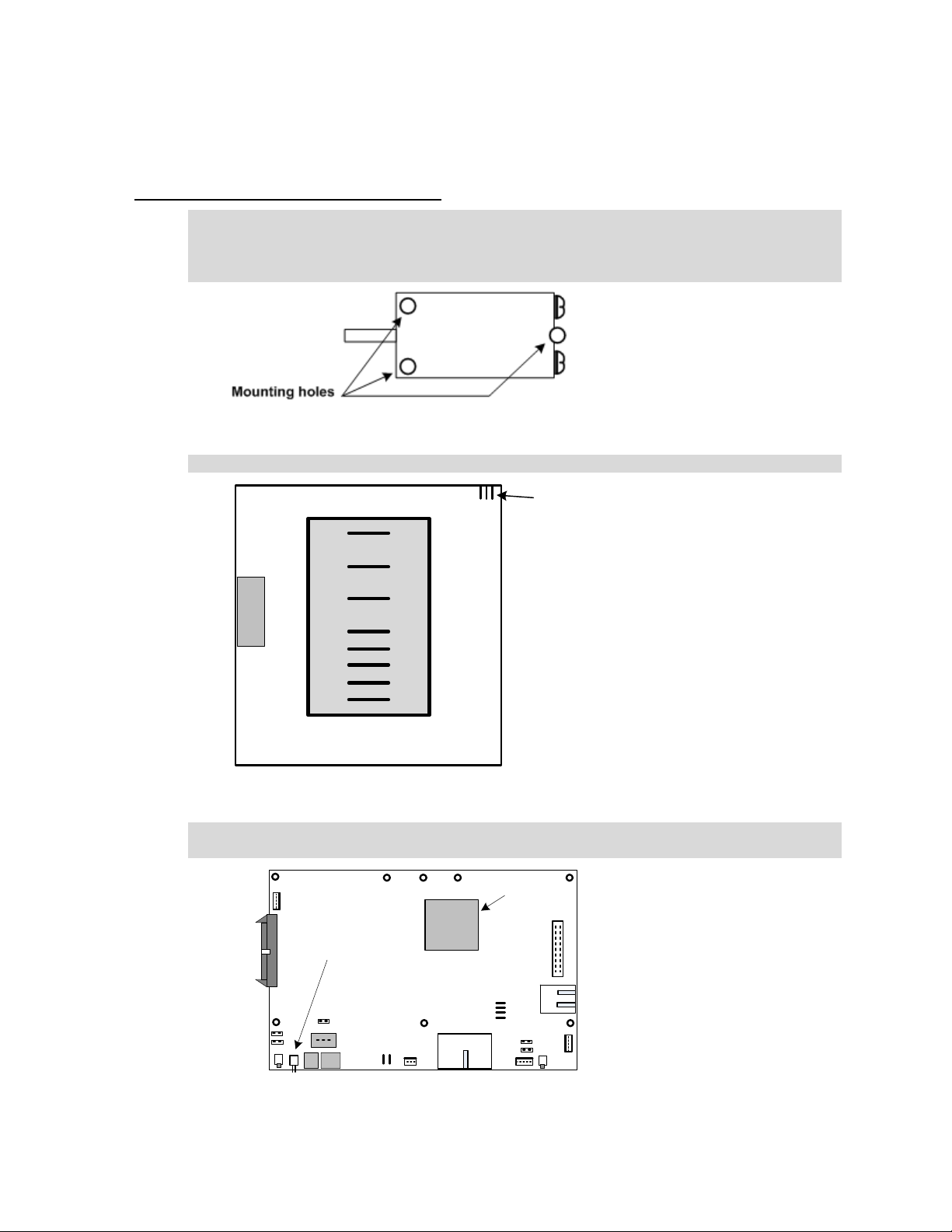
Mounting the IEI eMerge Cabinet
The IEI eMerge cabinet has four holes in the back of the cabinet for mounting to the wall as
shown in the diagram below.
The IEI eMerge cabinet mounting hole locations.
In addition there are 8 cable minder mounting holes in the cabinet. In the parts bag that came
with your eMerge system you will find plastic cable minders that can be inserted into the mounting
holes and then turned to secure them.
Mounting hardware should be sufficient to hang a 25 pound (11.34 kg) load. Wall space required
is 17” (44 cm) wide by 18” (46 cm) tall. The door opens from the top down. The open door is held
in a horizontal position by retaining cables and provides a handy flat work surface.
Document #: 6047001-UL, Rev 3.0
15
Page 16
Wiring a Battery
The IEI eMerge does not include a pre-mounted battery. However, a battery is required in order
to provide sufficient time for an orderly shutdown in case of power failure. If no battery is installed
data can be lost.
The battery can be placed on the floor of the cabinet on the left side beneath the power supply.
The battery specification is 12V DC, 7 AH, SLA (sealed lead acid). The battery cable must be
wired to a 3-pin connector for the Controller/Node board, with the center position empty. See the
diagram below. Battery standby power has not been investigated by UL.
Do not connect a battery before external power is supplied. It will immediately power up the
Controller/Node board and begin to drain the limited battery power. Once external power is
supplied you can connect the battery and it will charge at 12V via the connection with the
Controller/Node module.
NOTE: The battery is not meant to function as a backup or to provide standby power but rather
only to supply sufficient time to perform an orderly shutdown in case of power failure.
Controller/Node module DC and battery power connectors.
CAUTION!!! DO NOT CONNECT THE BATTERY TERMINALS TO THE POWER SUPPLY!
The power supply has labeled battery connections but it must not be used to connect a battery.
See the diagram on the next page. If a battery is installed it must be connected only to the 3-pin
battery connector on the Controller/Node module as shown in the diagram above. The battery will
charge via this connection.
IMPORTANT NOTE: The battery connection is Non-Power Limited. The battery wires must
be routed a minimum of ¼” (.250 inches) away from all other wiring within the enclosure.
There are tie-wrap loops built into the rear of the enclosure that can be used to secure the
wiring.
Document #: 6047001-UL, Rev 3.0
16
Page 17
Wiring Power to the IEI eMerge
Wiring AC Power
AC power must be provided to the eMerge system by using the wall socket transformer
provided. The transformer must be powered with 120V AC at 50-60 Hz. Power should come
from a separate circuit
50VA.
with an isolated earth ground. The transformer will output 24VAC at
To wire AC power
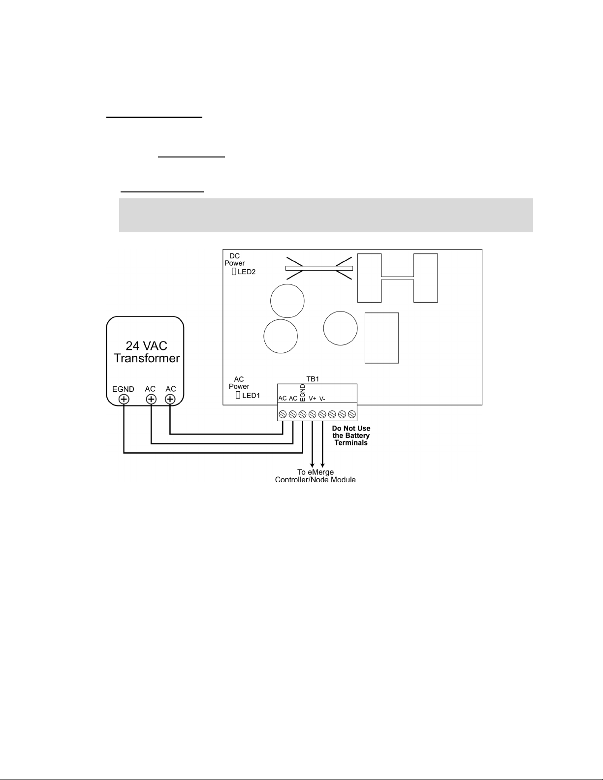
1. Wire the transformer to the power supply by connecting the two AC terminals on the
transformer to the two AC terminals on the power supply, and connecting the Ground
terminal to the EGND terminal on the power supply, as shown below.
Document #: 6047001-UL, Rev 3.0
17
Page 18
2. Wiring from the transformer to the power supply should be run through conduit into the
eMerge cabinet through a knockout in the side of the cabinet.
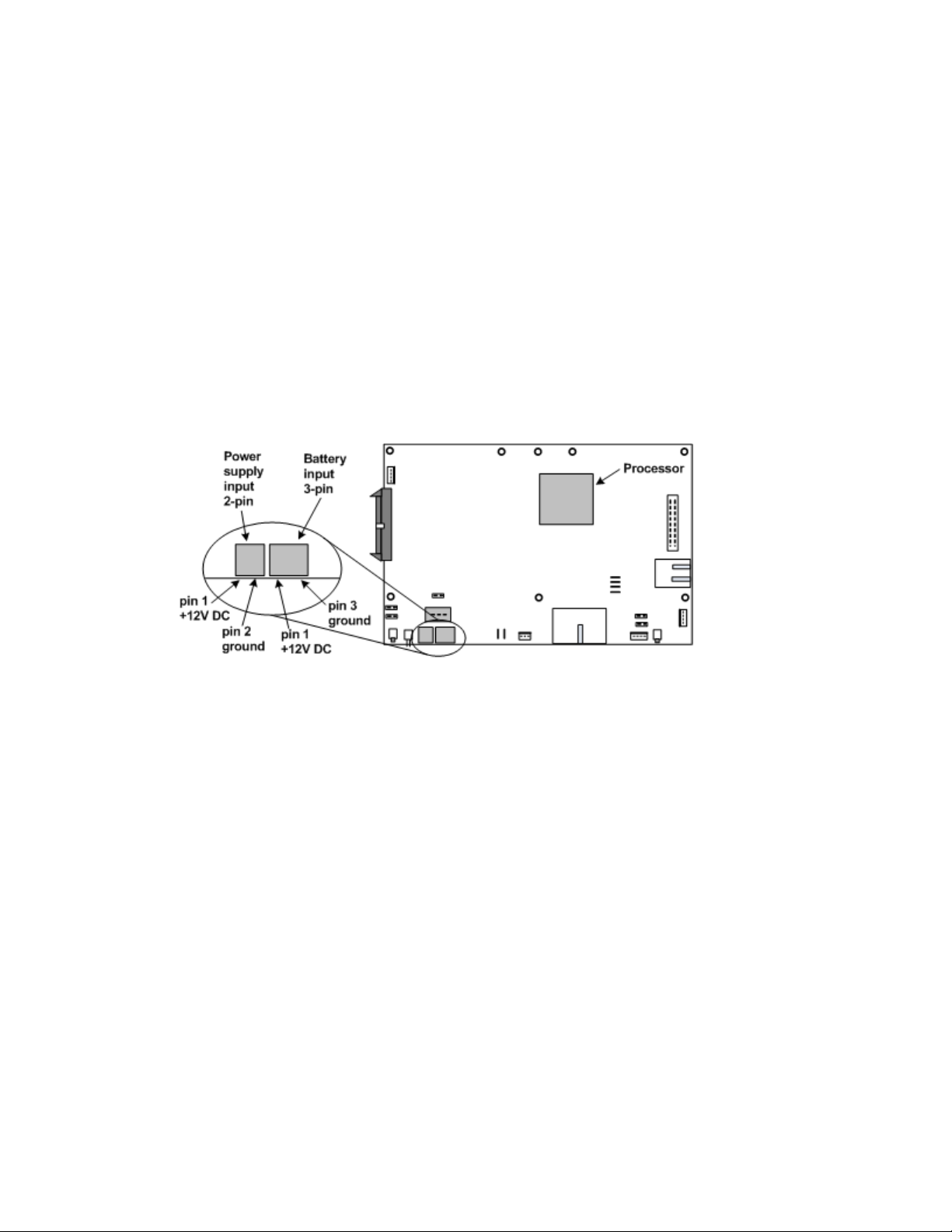
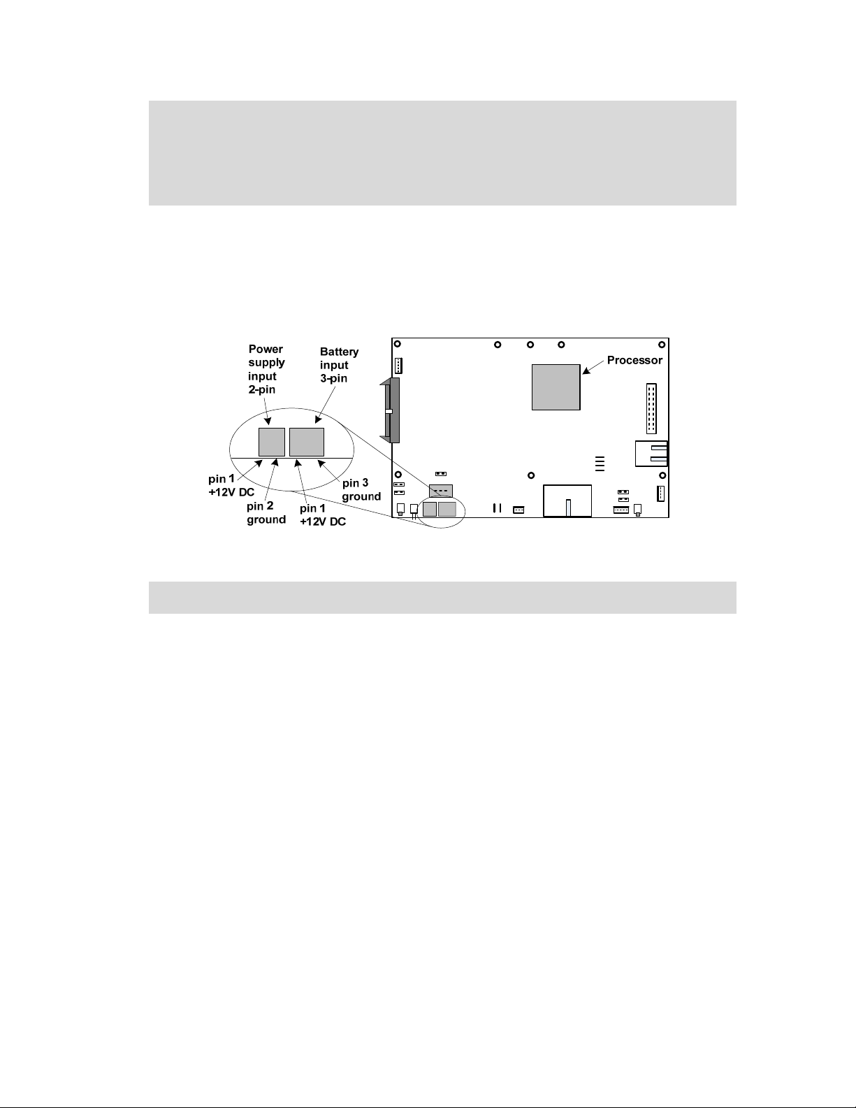
3. The IEI eMerge power supply comes pre-wired to the Controller/Node module. The DC
output of the power supply has 2 terminals labeled V+ and V-. See diagram above. The
DC output terminals are wired to a two 2-pin connector and plugged into the power supply
input on the Controller/Node module. See diagram below.
IMPORTANT NOTE: The power supply output is Non-Power Limited. The power supply
wires must be routed a minimum of ¼” (.250 inches) away from all other wiring within
the enclosure. There are tie-wrap loops built into the rear of the enclosure that can be
used to secure the wiring.
Controller/Node board DC and battery power connectors.
4. Plug the transformer into a wall socket and secure it in place with the socket ground screw
to ensure that power will not be accidentally interrupted.
Document #: 6047001-UL, Rev 3.0
18
Page 19
Connecting Readers
eMerge Access modules have two 7-pin reader connectors mounted on the board as shown in
the diagram below.
7-pin reader
connectors
The eMerge Access Control Module. (part number: eMerge ACM)
Important Note: Each eMerge Access Control Module can supply a total of 400 milliamps of
power for readers. If the reader(s) connected to the access module draw more than 400
milliamps then external a UL Listed, power-limited power supply must be used to power the
reader. Please refer to the section entitled: “Wiring readers using external a UL Listed, powerlimited power supply” for further details.
The color-coded wires from the reader wiring harness must be connected to the 7-pin connector
provided as shown in the diagram below. The color-coding for Power (red), Ground (black), Data
0 (green), and Data 1 (white) is Security Industry Association (SIA) standard.
Reader Beeper control varies by manufacturer and model. Refer to the documentation provided
by the reader manufacturer for details on your particular reader. Typically the reader will beep for
the duration of a momentary unlock or until the door is opened. This occurs whether the door is
unlocked by a valid card read or unlocked from the security application. If no beeper is desired,
do not connect the beeper control wire.
Reader LED control varies by manufacturer and model. Some use two-wire LED control and
some use one-wire control. Refer to the documentation provided by the reader manufacturer for
details on your particular reader. IEI does not support control involving signal pulsing to change
LED color.
#1
#2
2-pin inputs
3-pin outputs
Ribbon cable
connector
The eMerge Access module has both red and green LED control connections. See the connector
diagram in the procedure below.
The table below shows the state of the LED Control leads from the Access module for each
reader state. For Invalid Reads the leads are set for 2 seconds. For Valid Reads the leads are set
until the door opens or times out.
Reader State
Normal Low Low
Invalid Read Low High
Valid Read High Low
The table below shows the LED display color in one-wire readers depending upon which lead
from the Access module is used for connecting the wire.
Reader State
Normal Green Green
Invalid Read Green Red
Valid Read Red Green
Red LED Control lead
from the Access module
LED one-wire control to
Red LED Control lead
Green LED Control lead
from the Access module
LED one-wire control to
Green LED Control lead
Document #: 6047001-UL, Rev 3.0
19
Page 20
In a typical 2-wire reader the LED display would be as follows:
Reader State LED Display
Normal Yellow
Invalid Read Red
Valid Read Green
NOTE: LED display behavior for your particular reader may vary. Refer to the reader
manufacturer documentation.
CAUTION!!! MAKE SURE ALL POWER IS OFF BEFORE CONNECTING READERS, INPUTS,
OR OUTPUTS.
Wiring Readers
1. Power down the IEI eMerge. To ensure that the security database is properly saved use
the System Shutdown utility. The shutdown procedure includes saving the security
database. Select Setup : System Maintenance : Utilities : System Shutdown.
2. Be sure that you are grounded and pull the wiring through a knockout in the IEI eMerge.
Wire specification: Twisted, shielded, gauge as required. Maximum distance: 500 feet
(152 meters).
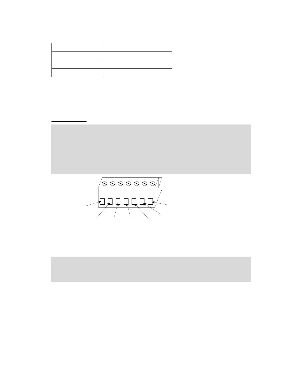
3. Connect the reader wires to the 7-pin reader connector provided as shown in the diagram
below.
Pwr
(red)
Gnd
(black)
D0
(green)
D1
(white)
Red LED control
The 7-pin reader connector wiring. CAUTION! See reader manufacturer documentation for
wire color for LEDs and Bpr (Beeper).
Bpr
Grn LED control
4. Be sure there is no power to the IEI eMerge and plug the connector into a reader position
on the Access module.
5. Record on an Access Module Installation Description Form (make a copy from Appendix
D) the exact position number for this particular reader.
Document #: 6047001-UL, Rev 3.0
20
Page 21

Wiring Readers using an External UL Listed, power-limited power supply
1. Power down the IEI eMerge. To ensure that the security database is properly saved use
the System Shutdown utility. The shutdown procedure includes saving the security
database. Select Setup : System Maintenance : Utilities : System Shutdown.
2. Be sure that you are grounded and pull the wiring through a knockout in the IEI eMerge.
Wire specification: Twisted, shielded, gauge as required. Maximum distance: 500 feet
(152 meters).
3. Connect the reader wires (D0, D1, Red LED, Green LED and Beeper only) to the 7-pin
reader connector provided as shown in the diagram below.
4. Connect your external power supply output V+ (positive voltage) and V- (GND) to your
reader (see the reader manufacturer’s documentation for power supply specifications and
connection information).
5. Connect the V- (GND) connection from your external power supply to the GND terminal
on the reader connector, shown below.
Bpr
Grn LED control
Red LED control
Gnd
(black)
D0
(green)
D1
(white)
The 7-pin reader connector wiring. CAUTION! See reader manufacturer documentation for
wire color for LEDs and Bpr (Beeper).
6. Be sure there is no power to the IEI eMerge and plug the connector into a reader position
on the Access module.
7. Record on an Access Module Installation Description Form (make a copy from Appendix
D) the exact position number for this particular reader.
Document #: 6047001-UL, Rev 3.0
21
Page 22

Connecting Inputs
Inputs can be connected either to an Access module or to an Input module.
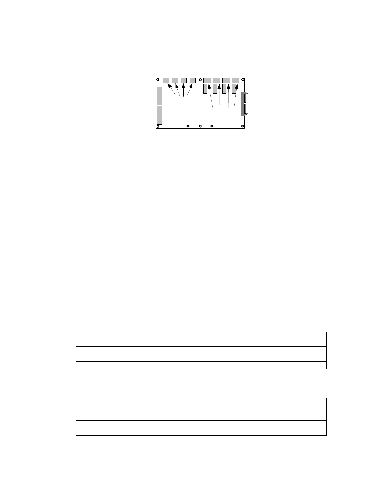
eMerge Access modules have four male 2-pin input connectors mounted on the board as shown
in the diagram below.
1 2 3 4
positions
2-pin inputs
Positions 1, 2, 3, and 4 on the eMerge Access module are inputs 1, 2, 3, and 4.
Ribbon cable
connector
If more inputs are required beyond the four provided on the eMerge Access module then
additional Access modules or Input modules can be installed in the IEI eMerge. To install
additional modules see the section “Installing Additional Modules” on page 11.
eMerge Input modules have eight (8) male 2-pin input connectors mounted on the board as
shown in the diagram below.
1 2 3 4 5 6 7 8
positions
2-pin inputs
The eMerge Input module. (part number: eMerge INP)
Ribbon cable
connector
CAUTION!!! MAKE SURE ALL POWER IS OFF BEFORE CONNECTING READERS, INPUTS,
OR OUTPUTS.
Wiring Inputs
1. Power down the eMerge. To ensure that the security database is properly saved use the
System Shutdown utility. The shutdown procedure includes saving the security database.
Select Setup : System Maintenance : Utilities : System Shutdown.
2. Click the Shutdown Now button.
3. Be sure that you are grounded and pull the wiring through a knockout in the eMerge
cabinet. Wire specification: Twisted, shielded 22 AWG Belden #9462 or equivalent.
Maximum distance: 2000 feet (610 meters).
4. Connect the input wires to the 2-pin input connector provided.
5. Be sure there is no power to the eMerge and plug the connector into an input position on
an Access module or an Input module. These connectors are polarized and can only be
inserted one way.
6. If you are connecting previously wired or previously installed inputs, determine the input
supervision type: normally open (NO) or normally closed (NC), zero, one, or two resistors,
single resistors in parallel or series. Note this on the Installation Description Form. You will
Document #: 6047001-UL, Rev 3.0
22
Page 23

need to know this for the software setup of the input. See “Input Supervision Types”
below.
NOTE: The IEI eMerge supports the use of 1k Ohm resistors only.
7. If you are installing the input device refer to the input device manual to determine if the
device circuit is normally open (NO) or normally closed (NC). Select the input supervision
type you want and wire the resistor(s) as shown in “Input Supervision Types” below.
8. Record on an Access or Input Module Installation Description Form (make a copy from
Appendix D) the exact position number and input supervision type for this particular input
device.
Input Supervision Types
NOTE: The IEI eMerge supports the use of 1k Ohm resistors only.
Dual Resistor
NO Dual Resistor NC Dual Resistor.
The configuration of resistors shown above must be installed for supervised input resistance
values to be properly read by the eMerge. The four states of the Dual Resistor input circuits
are read according to the values in the table below.
Input State Resistance Values
Normal 1k Ohms
Alarm 0.5k Ohms or 2k Ohms
Short 0 Ohms
Open No current (∞ Ohms)
Document #: 6047001-UL, Rev 3.0
23
Page 24

NC Parallel Resistor
The three states of the NC Parallel Resistor input circuits are read according to the values in
the table below.
Input State Resistance Values
Normal 0 Ohms
Alarm 1k Ohms
Open No current (∞ Ohms)
NC Series Resistor
The two states of the NC Series Resistor input circuits are read according to the values in
the table below.
Input State Resistance Values
Normal 1k Ohms
Alarm No current (∞ Ohms)
NC Unsupervised
The two states of the NC Unsupervised input circuits are read according to the values in the
table below.
Input State Resistance Values
Normal 0 Ohms
Alarm No current (∞ Ohms)
Document #: 6047001-UL, Rev 3.0
24
Page 25

NO Parallel Resistor
The three states of the NO Parallel Resistor input circuits are read according to the values in
the table below.
Input State Resistance Values
Normal 1k Ohms
Alarm 0 Ohms
Open No current (∞ Ohms)
NO Series Resistor
The two states of the NC Series Resistor input circuits are read according to the values in
the table below.
Input State Resistance Values
Normal No current (∞ Ohms)
Alarm 1k Ohms
NO Unsupervised
The two states of the NO Unsupervised input circuits are read according to the values in the
table below.
Input State Resistance Values
Normal No current (∞ Ohms)
Alarm 0 Ohms
Document #: 6047001-UL, Rev 3.0
25
Page 26

Connecting Outputs
Outputs can be connected either to an Access module or to an Output module.
eMerge Access modules have four 3-pin output connectors mounted on the board as shown in
the diagram below.
3-pin outputs 1 2 3 4
NOTE: Output positions on the eMerge Access module are outputs number 1, 2, 3, and 4.
connector
If more outputs are required beyond the four provided on the eMerge Access module then
additional Access modules or Output modules can be installed in the IEI eMerge. To install
additional modules see the section “Installing Additional Modules” on page 11.
eMerge Output modules have eight (8) male 3-pin output connectors mounted on the board as
shown in the diagram below.
Ribbon cable
1 2 3 4 5 6 7 8
positions
3-pin outputs
The eMerge Output module. (part number: eMerge OUT)
Ribbon cable
connector
CAUTION!!! THE DIODES AND VARISTORS SHOWN BELOW MUST BE INSTALLED AS
SHOWN. THEY ARE DESIGNED TO PROTECT THE OUTPUT CIRCUITS. FAILURE TO
PROPERLY INSTALL THE DIODES OR VARISTORS MAY REDUCE THE RELAY CONTACT
LIFE AND LEAD TO PREMATURE FAILURE!
CAUTION!!! MAKE SURE ALL POWER IS OFF BEFORE CONNECTING READERS, INPUTS,
OR OUTPUTS.
Wiring Outputs
1. Power down the IEI eMerge. To ensure that the security database is properly saved use
the System Shutdown utility. The shutdown procedure includes saving the security
database. Select Setup : System Maintenance : Utilities : System Shutdown.
2. Be sure that you are grounded and pull the wiring through a knockout in the eMerge
cabinet. Wire specification: Twisted, shielded, gauge as required. Maximum distance:
2000 feet (610 meters).
3. Refer to the output device manual to determine if the device is normally energized or
normally not energized, and if it is DC or AC powered.
4. Connect the output wiring to the 3-pin output connector. Pin 1 is normally closed (NC). Pin
2 is common. Pin 3 is normally open (NO).
Document #: 6047001-UL, Rev 3.0
26
Page 27
5. Be sure there is no power to the eMerge and plug the connector into an output position on
an Access module or an Output module. These connectors are polarized and can only be
inserted one way.
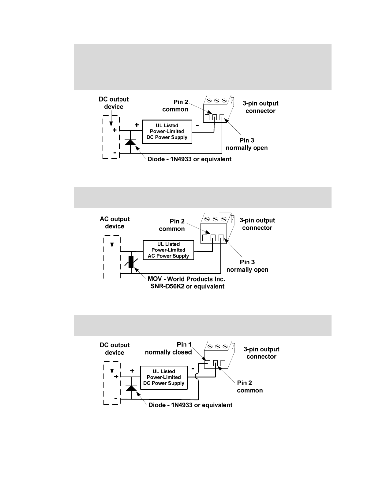
6. If the output device is DC powered and normally not energized then install a diode
(1N4933- 1 A, 50 V, Fast Recovery Diode or equivalent) in the circuit as shown in the
diagram below.
Typical wiring for a DC output device that is normally not energized.
7. If the output device is AC powered and normally not energized then install a varistor
(40 VAC, 56 VDC, 10 A Surge, Radial Leaded Varistor or equivalent, e.g. World Products
Inc. SNR-D56K2) in the circuit as shown in the diagram below.
Typical wiring for an AC output device that is normally not energized.
8. If the output device is DC powered and normally energized then install a diode
(1N4933- 1 A, 50 V, Fast Recovery Diode or equivalent) in the circuit as shown in the
diagram below.
Typical wiring for a DC output device that is normally energized.
Document #: 6047001-UL, Rev 3.0
27
Page 28

9. If the output device is AC powered and normally energized then install a varistor (40
VAC, 56 VDC, 10 A Surge, Radial Leaded Varistor or equivalent, e.g. World Products Inc.
SNR-D56K2) in the circuit as shown in the diagram below.
Typical wiring for an AC output device that is normally energized.
10. Record on an Access or Output Module Installation Description Form (make a copy from
Appendix D) the exact position number for this particular output device.
Connecting Elevator Relay Outputs
The IEI eMerge can supply and be configured for one output per elevator per floor. These outputs
will normally be connected to inputs on the elevator controller. Refer to the elevator
manufacturer’s documentation for specifics regarding access control for individual floors.
Refer also to “Wiring Outputs” starting on page 26.
CAUTION!!! MAKE SURE ALL POWER IS OFF BEFORE CONNECTING READERS, INPUTS,
OR OUTPUTS.
Wiring Elevator Relay Outputs
1. Power down the IEI eMerge. To ensure that the security database is properly saved use
the System Shutdown utility. The shutdown procedure includes saving the security
database. Select Setup : System Maintenance : Utilities : System Shutdown.
2. Be sure that you are grounded and pull the wiring through a knockout in the eMerge
cabinet. Wire specification: Twisted, shielded, gauge as required. Maximum distance:
2000 feet (610 meters).
3. Connect the output wiring to the 3-pin output connector. Pin 1 is normally closed (NC). Pin
2 is common. Pin 3 is normally open (NO).
4. Be sure there is no power to the eMerge and plug the connector into an output position on
an Access module or an Output module. These connectors are polarized and can only be
inserted one way.
5. Connect the elevator controller inputs to the elevator controller module. Refer to the
elevator manufacturer’s documentation to determine proper wiring for access control
inputs to the elevator controller module.
6. Record on an Access or Output Module Installation Description Form (make a copy from
Appendix D) the exact position number for this particular elevator floor output.
Document #: 6047001-UL, Rev 3.0
28
Page 29

Connecting to the Network and Setting Initial Values
Now that you have completed the hardware installation you must use a browser (such as Internet
Explorer™ or Mozilla Firefox) to view the IEI eMerge Init Mode page and complete initial IP network
and other settings and complete the network connection. UL has evaluated the eMerge as a standalone system only. Connection to the PC is not relied upon for proper system operation.
NOTE: The eNC default IP address is 192.168.0.250. If that address already exists on the network do
not connect to the network until you have changed the IP address. Use the procedure “Setting the
eNC IP address by directly connecting a PC” on page 30. See the network administrator for an
available IP address.
Wiring the network connection
1. Pull the Ethernet cable through a knockout in the eMerge cabinet. Cable specification:
CAT 5 or better with an RJ-45 connector wired straight through connecting to a network
hub or switch.
2. Plug the RJ-45 connector into either of the 2 network switch ports on the Controller/Node
module mounted in the topmost slot of the eMerge cabinet. See the diagram below.
Processor
Network switch
2-port
The Controller/Node module has a 2-port network switch for network connections.
LEDs
3
4
5
6
3. If the network connection is functioning properly the Amber LED on the network switch will
light and LED #5 will light green. For specifics on the Controller/Node module LEDs see
page 43
The eMerge Node only module has one network port.
4. If the IEI eMerge you are installing is a node only (has no eNC populated on the
Controller/Node module) then run the external cable directly to the Node, and plug the RJ45 connector into the network port on the Node as shown in the diagram above.
Document #: 6047001-UL, Rev 3.0
29
Page 30

Setting Initialization Values
This is a three step process:
• Display the Init Mode page.
• Complete the settings (with information from the network administrator).
• Save the settings and reboot.
Step one: use one of the following procedures to display the Init Mode page.
To view the IEI eMerge Init Mode page
1. Open a browser window on a computer connected to the network.
2. In the browser address field enter 192.168.0.250. This is the eNC default IP address.
3. Init Mode page should now display. Complete initial IP network and other settings as
explained below under DHCP, Time, and Email Settings.
If the Init Mode page does not display check the computer’s IP address
1. In Windows™ select Settings : Control Panel : Network Connections.
2. Double click Local Area Connections and select the Support tab. Your computer must
have an IP address of 192.168.0.x. (x must be a value from 0 to 254.) If your network
connected computer does not have this IP address then check with the network
administrator for appropriate IP addresses and use the procedure below to set the eNC IP
address.
Setting the eNC IP address by directly connecting a PC
1. Connect a computer directly to the network switch on the eNC with an Ethernet cable. See
page 42 for a diagram of the eNC.
2. Use the network control panel to change the laptop IP address to an address on the
192.168.0.x network. (x must be a value from 0 to 254.) In Windows™ select Settings :
Control Panel : Network Connections.
3. Double click the Local Area Connection.
4. Click the General tab Properties button to display the Local Area Connection Properties
dialog.
5. Click the General tab and select Internet Protocol (TCP/IP).
6. Click the Properties button to display the Internet Protocol Properties dialog.
7. Click the General tab and select Use the following IP address.
8. Enter an IP address of 192.168.0.x and click OK. (x must be a value from 0 to 254.)
9. Click OK to dismiss the Local Area Connection Properties dialog.
10. Reboot the computer, launch the browser, and in the browser address field enter
192.168.0.250
11. Init Mode page should now display. Complete the initial IP (network) settings as explained
below.
12. Once the initial IP settings are completed you will have to reboot not only the security
application but also the eMerge Network Node. This is necessary because the Node will
need to acquire a new valid IP address from the network DHCP server. To reboot the
Node remove its power cable and wait at least 30 seconds (until the LEDs turn off) before
Document #: 6047001-UL, Rev 3.0
30
Page 31

reconnecting it. Refer to the Controller/Node module diagrams on page 43. The wait is
necessary because the Node has an on-board battery.
Step two: Now that you have reached the Init Mode page complete the settings as explained below.
These settings may require information from the network administrator.
Network Controller Settings
DHCP client?:
NO is the default and recommended setting. This ensures that the IP address given to
the eNC is static. That is, it will not change.
Obtain from the Network Administrator:
• The static IP address to assign to the Network Controller.
• The appropriate Netmask.
• The Gateway IP address.
• DNS (Domain Name Server) IP addresses.
Enter these addresses into the appropriate text boxes in this section.
If “DHCP Client?” is set to YES then the IP address of the eNC will periodically change. In
this case the network administrator must ensure that the IP address that is leased to the
eNC will have a consistent DNS name that is known to security application users. This
requires an onsite DNS server because the DNS name is the only way that users can
browse to the IEI Security Application if the IP address has changed.
In addition, if this is set to YES the other fields in this group will be grayed because the
DHCP server will supply the IP data dynamically.
IP address:
If “DHCP client?” is set to YES then this field will be grayed.
See the network administrator for an appropriate IP address and enter it here.
The default value is 192.168.0.250. An IP address entered here is a static IP address. That
is, it will not change.
Netmask:
If “DHCP client?” is set to YES then this field will be grayed.
See the network administrator for this netmask number and enter it here.
The default value is 255.255.255.0.
Gateway:
If “DHCP client?” is set to YES then this field will be grayed.
See the network administrator for this gateway IP address and enter it here.
The default value is 192.168.0.1. This is the address of the router that connects the eNC to
the rest of your network or to the Internet.
DNS 1:
If “DHCP client?” is set to YES then this field will be grayed.
See the network administrator for this DNS (Domain Name Server) IP address and enter it
here.
Document #: 6047001-UL, Rev 3.0
31
Page 32

The default value is 192.168.0.1.
DNS 2:
If “DHCP client?” is set to YES then this field will be grayed.
See the network administrator for this DNS (Domain Name Server) IP address and enter it
here.
The default value is 192.168.0.1.
Node Addressing Settings
There are three ways for nodes to acquire their IP addresses. An existing DHCP server on the
network can automatically assign IP addresses to nodes, you can set a static IP address for each
node, or the network controller can serve IP addresses to any of its Nodes on the network.
Typically IP addressing is done by a customer’s existing DHCP server. However, there may be
cases where the Network Controller and its nodes are on a separate network, a separate subnet,
or a network with no DHCP server. In other cases the network administrator may wish to specify
IP addresses for the network controller and its nodes even when there is a DHCP server on the
network. In any of these cases you may wish to have the Network Controller serve IP addresses
to its nodes. See the CAUTION below.
Addressing Method:
• DHCP: This is the default setting. It allows an existing DHCP server on the network to
automatically assign IP addresses to nodes.
The Start address, Number of addresses, and Netmask fields will be grayed when DHCP
is the addressing method.
• Network Controller: This setting enables the Network Controller to serve IP addresses to
any of its Nodes on the network.
CAUTION: While the NC’s addressing method can exist alongside a standard DHCP
server, care should be taken when specifying the valid address range for the NC so as not
to conflict with the DHCP server’s valid address range. Therefore, ensure that the network
administrator agrees with setting this up and provides an accurate Start address, Number
of addresses, and Netmask.
• STATIC: This setting requires that you set a static IP address for each node. You must
ensure that the static address assigned to a node is not assigned to any other device on
the network.
The Start address, Number of addresses, and Netmask fields will be grayed when
STATIC is the addressing method.
Setting a node to a static IP address
1. Make sure that the Microsoft™ .NET Framework v 1.1 is installed on the network
connected pc you are working from. The .NET Framework Installer is on the CD provided
to you. It can also be downloaded from the Microsoft website.
2. Run nnconfig.exe. This program is on the CD provided. You can run this directly from the
CD.
NOTE: The pc running nnconfig.exe and the Node(s) you are configuring must be on the
same subnet.
3. Nnconfig.exe listens for the node(s) multicast message and lists all nodes that it hears in
the large list box. Allow nnconfig.exe several moments to discover the Network Node(s)
that exist on the network.
Document #: 6047001-UL, Rev 3.0
32
Page 33

4. The Auto Discover NC checkbox is checked by default. This instructs the nodes to autodiscover the network controller. If the NC is on a separate subnet from the node(s)
uncheck the Auto-Discover NC (multicast) checkbox and enter the IP address of the
network controller into the NC IP Address text box. The node(s) should now find the
network controller.
5. If the network controller is on a remote subnet, routers and firewalls may not allow the
node to connect with the network controller. In such a case it is necessary to open TCP
Port 7262 to allow the node to connect to the network controller. Discuss this with the
network administrator.
6. From the large list box, select the node you wish to assign a static IP address to.
7. From the IP Address Method drop-down select Static.
8. In the IP Address textbox enter the static IP address you will use for this node. Be sure to
get this number from the Network Administrator.
9. In the Netmask and Gateway text boxes enter the netmask and gateway IP address for
this node. Be sure to get these numbers from the Network Administrator.
10. Click Save. This node now has a static IP address that will not change.
Start address:
If “Addressing Method” is set to STATIC or DHCP this field will be grayed.
A value is entered here only if the Network Controller is the addressing method. Enter in this
field the first valid IP address (in dot notation) in the available pool of addresses. Obtain this
IP address from the network administrator.
Number of addresses:
If “Addressing Method” is set to STATIC or DHCP this field will be grayed.
A value is entered here only if the Network Controller is the addressing method. Enter in this
field the number of IP addresses available in the local network pool of IP addresses. For
example, a “Start address” of 192.168.0.15 with the “Number of addresses” set to 25 will
have IP addresses of 192.168.0.15 through 192.168.0.39. Obtain this number from the
network administrator.
Netmask:
If “Addressing Method” is set to STATIC or DHCP this field will be grayed.
A value is entered here only if the Network Controller is the addressing method. Enter in this
field a subnet mask in dot notation. The default value is 255.255.255.0. Obtain this subnet
mask from the network administrator.
Time Settings
Use of an NTP network time server ensures that the Controller/Node module will be regularly
synchronized with the exact time used by all other network resources. At least one time
server must be designated for the Controller/Node to synchronize its own time. If no
timeserver is available the Controller/Node clock may drift slightly over time.
NOTE: You can also manually set the time using this page. If you set the time manually be
sure to set it to standard time, not daylight savings time. The Timezone setting will
automatically adjust for daylight savings time (summer time).
Current eNC Time:
This displays the current time of the Controller/Node clock.
Document #: 6047001-UL, Rev 3.0
33
Page 34

Manually Set Date/Time:
If there will be no network timeserver available for the Controller/Node then select from the
date and time dropdown lists to manually set the time.
If you set the time manually be sure to set it to standard time, not daylight savings time. The
Timezone setting will automatically adjust for daylight savings time (Summer time).
Timeserver 1: <DNS host address name>
The default name in this field is pool.ntp.org. If the IEI eMerge is installed on a network with
Internet access then this default setting need not be changed.
NOTE: If there is no Internet access then:
• The network administrator must supply you with a local network timeserver name or
the time will have to be manually set.
• If the time must be manually set then remove the timeserver name from this field or
the network controller will spend several minutes searching for this server. Until this
search times out you will not be able to continue completing the Init Mode settings.
Timeserver 2: <DNS host address name>
The default preset name in this field is pool.ntp.org.
Timeserver 3: <DNS host address name>
The default preset name in this field is pool.ntp.org.
Timezone: < >
Select from the dropdown list the appropriate timezone for your area.
The default preset value in this field is US/Eastern.
Email Settings
Email relay: <server address or name>
Enter the IP address or DNS name of the mail relay server. The network administrator can
supply you with this address or name.
The mail server must be setup to allow open relay of email sent from the IP address of the
eNC. The network administrator can setup this relay.
From email address: <source address>
Enter an email sender name for the eNC. Messages from the eNC will display this source
address in the “From” field.
The mail administrator should direct any email sent to this address to a security
administrator.
Web Server Setting
Web Server Port:
See the network administrator for this number and enter it here. The default value is 80.
Document #: 6047001-UL, Rev 3.0
34
Page 35

Init Mode Setting
Init Mode:
Typically this value should be changed to NO.
If this value is left at YES then the Init Mode page will display after each boot of the eNC.
You can return to the Init Mode page from the security application by selecting Setup : Site
Settings : Network Controller.
Step three: Now that you have completed the initial settings you must save them and reboot the
system.
To save the IP settings and launch the security application
1. Click the Save button. The IP settings are saved.
2. Click the Reboot button to restart the IEI Security Application. This may take several
minutes.
3. If the Init Mode page settings were completed with a directly connected laptop instead of a
network connected computer then you will have to reboot not only the security application
but also the eMerge Network Node. This is necessary because the Node will need to
acquire a new valid IP address from the network DHCP server. To reboot the Node
remove its power cable and wait at least 30 seconds (until the LEDs turn off) before
reconnecting it. Refer to the Controller/Node module diagrams on page 43. The wait is
necessary because the Node has an on-board battery.
4. Open a browser window on a computer connected to the network and enter in the
Address box the IP address that you set for the eNC.
5. At the Login page enter the user name “admin.”
6. Enter the password “admin.”
7. Click the Go button.
Using the Console Port to Obtain an IP Address
NOTE: This procedure will normally not be necessary unless the IP address of the eNC is
unknown.
You can obtain the IP address of the eNC by using a terminal emulator to communicate with the
eNC via the console port.
1. Connect the console port on the eNC to a serial port on a PC using a serial cable with a
DB9 connector. For the location of the console port see the diagram of the eNC board on
page 42.
2. Set your terminal emulator to the following settings: BPS=115200, 8 data bits, no parity, 1
stop bit, no hardware flow control, no software flow control.
3. Login to the eNC with the user name “admin” and the password “admin.” (Use all lower
case.)
4. The eNC will report its current IP address and you can set a new IP address.
Document #: 6047001-UL, Rev 3.0
35
Page 36

Information for Network Administrators
How Nodes and the Network Controller Use the Network
(Versions 1.4 and higher)
1. When a Node boots it initially selects for itself a temporary random IP address in the
zeroconf address space (169.254.X.Y where X and Y are randomly selected).
2. The Node then multicasts for a Network Controller at 224.0.72.62 UDP port 7262,
and presents its Unique Identifier (UID).
3. A Network Controller answers the multicast at 224.0.72.62 UDP port 7262 providing
its own IP address and presents an addressing method for the Node. See “Setting
Initialization Values” on page 30.
• There are three IP addressing methods available:
1. An existing DHCP server on the network can assign IP addresses.
2. A Static IP address can be assigned using nnconfig.exe This program is
available on the Support page of the IEI web site for download
(www.ieib.com). You will need a user name and password. Call IEI Support
at (781) 821-5566.
3. The Network Controller can provide IP addresses to Nodes only from a
specified address range.
4. Once a proper IP address for the Node is selected further communications between
Node and Network Controller occur directly between their respective IP addresses
using TCP port 7262.
5. The Network Controller may also require:
• TCP Port 23 open for Telnet server access. This can be used for remote
debugging. The Telnet Server is disabled by default.
• TCP Port 3000 open for communication from video management system inputs.
• TCP Port 3306 open for MySQL report usage
Document #: 6047001-UL, Rev 3.0
36
Page 37

Network Port Usage Table
(Versions 1.4 and higher)
TCP Port 80
TCP Port 443
TCP Port 7262
TCP Port 23
TCP Port 3000
TCP Port 3306 Must be open to the Network Controller for MySQL report usage.
TCP Ports 20, 21
Must be open to the Network Controller for Browsers to access the
Security Application. This can be configured on a different port.
Must be open to the Network Controller for Browsers to access the
Security Application using HTTPS (SSL). This can be configured on
a different port.
Must be open to the Network Controller for communications
between the Controller and Nodes. Be sure that this port is open
through routers and firewalls for any Nodes on different subnets
from the Network Controller.
Must be opened to the Network Controller using a jumper on the
Controller for Telnet access to the Controller.
Must be open to the Network Controller for the Video Management
System virtual inputs to communicate camera up/down and motion
detection messages.
When using active FTP these ports must be open to the FTP server
for FTP backups from the Network Controller.
When using passive FTP port 20 will not be required.
Ports must also be left open to the Network Controller for FTP
server responses. The network administrator must set up these
ports
Network Port Usage Table
(Up to version 1.3)
Must be open to the Network Controller for the on-board TFTP server
TCP Port 69
NOTE: If you are updating a system from version 1.3 or lower you will need to leave port 69
open until the software update is complete. Once your version is 1.4 or higher you can close
port 69 as it will no longer be needed.
to pass software updates to the Nodes. This port can be opened
temporarily for updates and then closed again.
Document #: 6047001-UL, Rev 3.0
37
Page 38

Initial System Setup Checklists
Now that you have completed the initial IP settings you must complete the software system setup.
Log in and initial system setup
1. At the Login page enter the user name “admin.”
2. Enter the password “admin.”
3. Click the Go button.
4. The following checklists take you through steps in System Setup. The checklists are
ordered to ensure that prerequisite steps are completed first.
5. When system setup is completed be sure to change the “admin” account password.
Select Support/Utilities : Change Password.
6. Give the new password for the admin account to the network administrator or security
director.
SPECIAL NOTE: In the online Help you will find this checklist composed of links. From the Help
Table of Contents select “Initial System Setup Checklist.” Select each link in turn and it will take
you to the detailed Help topic for that step in the process.
From the Main Menu
Choose this
Setup : Site Settings :
Network controller
To do this
Specify eNC name, location, IP information, time zone,
and daily backup schedule. Enter support contact
information, picture URL and select an enrollment
reader.
Network nodes
Setup : Time :
Holidays
Time Specs
Document #: 6047001-UL, Rev 3.0
Configure each node’s resources.
Name holidays, specify start date and time, end date
and time, and holiday groupings. Holiday definitions are
needed for use in Time Specs.
Name time specifications, specify start time, end time,
select included weekdays and holiday groups. Time
Specs are needed for use in Access Levels, Portal
Group unlocking, Input Group arming, and Output Group
activation.
38
Page 39

Setup : Alarms :
Outputs
Output Groups
Inputs
Input Groups
Events
Setup : Access Control :
Card Formats
Person Sections
Name outputs, specify node, slot, and position. Output
configurations are needed for use in Output Groups,
Portal definitions, Events, and activation following alarm
Inputs.
Create groups of outputs. Select a time specification for
activating outputs in the group.
Name inputs, specify node, slot, and position. Enter an
output name as a following resource ID. Inputs are
needed for use in Input Groups, Events, and defining
Portals.
Create groups of inputs. Select a time specification for
arming inputs in the group.
Specify alarm events and system behavior in response
to the alarm event.
Specify a card format and bit length, enter start bits and
bit lengths for card ID, facility code, and issue code.
Specify what data appear on the personal information
page and label any user-defined data there.
Readers
Reader Groups
Portals
Portal Groups
Elevators
Access Levels
Name readers, specify node, slot, and position. Reader
configurations are needed for use in Reader Groups,
Portal definitions, and Access Levels.
Create Reader Groups. Reader Groups are needed for
use in Access Levels.
Define Portals to include card readers, alarm outputs, a
locking mechanism, a door switch monitor (DSM), and a
Request-to-Exit (REX) function.
Create Portal Groups and assign an Unlock Time Spec.
Define elevators, name secure floors and create floor
groups.
Define Access Levels to include Readers or Reader
Groups and Time Specs. Access Levels are needed for
assignment to individual card holders.
Document #: 6047001-UL, Rev 3.0
39
Page 40

Setup : Cameras :
Types
Definitions
Menu Order
Presets
Sequences
Views
Setup : Floorplans :
Upload
Configure
Enter camera types and setup URLs for each camera
used to control the pan, tilt, zoom, preset, and
brightness features.
Configure settings for cameras including DNS Name,
camera type, IP information, user name and password.
Set the order of cameras in the Main Menu and lists.
Record preset positions already defined at each camera
web site.
Setup a display sequence of preset camera positions.
Setup multi-camera collections in quad views and
picture-in-a-picture.
Upload an image of a site floorplan to the eNC in gif,
jpeg, or png formats.
Place system resources into a floorplan image.
Setup : Network Resources :
Domain Name Server
Email settings
Network storage
Time server
Setup : System Maintenance :
Backup Database
Once you have completed the initial setup it is strongly recommended that you backup the
database immediately to protect the configuration work you have just completed.
Enter IP addresses for DNS services.
Enter the email server that will relay notification
email from the eNC. Enter email account name and
alert email addresses.
Enter the name, user account name, and password
for network storage available for backing up eNC
data.
Enter name(s) of Network Time Servers available to
the IEI eMerge.
Enter a network storage location for security database
backups. Perform an immediate backup.
Document #: 6047001-UL, Rev 3.0
40
Page 41

System Administration and Monitoring
System Administration and Monitoring are focused on day-to-day tasks of using, managing, and
administering a site’s security using the IEI Security Application. It does not involve installation
and setup tasks.
The primary functions in System Administration are:
• monitoring cameras and floorplans.
• monitoring today’s activity log.
• issuing access cards.
• entering people and personal information into the security database.
• reviewing system reports.
• making backups of the security database.
For procedures and information regarding these, and any other System Administration and
Monitoring tasks, use the online Help system.
Document #: 6047001-UL, Rev 3.0
41
Page 42

Testing and Troubleshooting
The Controller/Node Module
The Controller/Node module is built in three different forms:
• Controller/Node module (part number: eMerge NC)
• Node-Only module (part number: eMerge BM)
• Controller-Only module
The Controller/Node module top side. (part number: eMerge NC)
The Controller/Node module bottom side.
Document #: 6047001-UL, Rev 3.0
42
Page 43

Network Controller LEDs
The right side of the eMerge Controller/Node module contains the components for the
Network Controller. It has 6 LEDs on the board and 2 LEDs on each network port.
LED 1 NC to NN
Activity
LED 2 NC to NN
Speed
LED 3 Not used.
LED 4 NN BLINKING GREEN: the blink count equals the
LED 5 NTWRK ON GREEN means network communication is
LED 6 SYS BLINKING GREEN means the system is
Network Amber LED ON means the network is connected.
Network Green LED BLINKING means data activity on the port.
BLINKING RED means NC is communicating to
the Node.
ON GREEN means 100 megabits per second.
OFF means 10 megabits per second.
node count. For example, 2 blinks means that 2
nodes are connected to the system.
functioning.
running.
Network Node LEDs
The left side of the eMerge Controller/Node module contains the components for the
Network Node. It has 10 LEDs.
LED 7 I2C RED, changes state when an application module
input or output occurs.
LED 8 RUN ON GREEN means the co-processor is powered
and initialized.
LED 9 ALRM ON RED means there is an error condition.
LED 10 NC RED means communication is active with the
Network Controller.
LED 11 RUN ON GREEN means the Node is powered and
initialized.
LED 12 NN to
NC Speed
ON GREEN means 100 megabits per second.
OFF means 10 megabits per second.
If the module is a Node-Only, LED 12 is not used
and the Network port Amber LED assumes this
function. See below.
Document #: 6047001-UL, Rev 3.0
43
Page 44

LED 13 NN to
NC Activity
LED 14 SYST Not used.
LED 15 Not used.
LED 16 PWR ON GREEN means power is properly connected.
BLINKING RED means Node is communicating to
the NC.
If the module is a Node-Only, LED 13 is not used
and the Network port Green LED assumes this
function. See below.
ON RED means polarity on the power connector is
reversed (incorrect). The Node will not function.
Network port
Amber LED
Network port
Green LED
ON means the network is connected.
BLINKING means data activity on the port.
The Node-Only Module
The Node-Only module is populated primarily on the left side (Node side). Note that the
Node-Only implementation has a network port that is not present in the other versions of this
module. Note also that on the bottom side of this module there is no I-button socket.
The Node-Only module top side. (part number: eMerge BM)
Document #: 6047001-UL, Rev 3.0
44
Page 45

The Node-Only module bottom side.
The Controller-Only Module
The Controller-Only module is populated primarily on the right side (Controller side). Note
that the bottom of the Controller-Only module has no battery mount.
The Controller-Only module top side.
Document #: 6047001-UL, Rev 3.0
45
Page 46

The Controller-Only module bottom side.
IEI eMerge Cabinet Door LED
The front of the IEI eMerge cabinet door has one LED.
If the cabinet contains a Controller-Node module the LED states are as follows:
Green steady The network communication is functioning and
external power is on.
Green flashing The network communication is functioning and
the eMerge is using battery power.
Red steady The network communication is not functioning
and external power is on.
Red flashing The network communication is not functioning
and the eMerge is using battery power.
If the cabinet contains a Node-only module the LED States are as follows:
Green steady External power is on.
OFF Battery power is on or the system has no power.
Document #: 6047001-UL, Rev 3.0
46
Page 47

Access Module and LEDs
2
LEDs
1
#1
7-pin reader
connectors
#2
The eMerge Access module. (part number: eMerge ACM)
3
LEDs
4
3-pin outputs2-pin inputs
Ribbon cable
connector
Access Module LEDs
The eMerge Access module has 4 LEDs on the board. They are read as follows:
LED 1 RUN ON GREEN means the module is powered and
initialized.
LED 2 I2C RED, changes state when input or output occurs.
LED 3 IN/RDR Not assigned.
LED 4 OUT Not assigned.
Input and Output Module LEDs
2
LEDs
1
The eMerge Input module. (part number: eMerge INP)
2-pin inputs
Ribbon cable
connector
Input and Output Module LEDs
The eMerge Input and Output modules have 2 LEDs on the board. They are read as follows:
LED 1 RUN ON GREEN means the module is powered and
initialized.
LED 2 I2C ON RED, BLINKS OFF when the Input/Output
module transmits a message to the Node.
Document #: 6047001-UL, Rev 3.0
47
Page 48

IEI eMerge Power Supply LEDs
The eMerge power supply has two LEDs.
The eMerge power supply LEDs.
LED 1 AC ON – AC power is present
OFF – AC power is not present
LED 2 DC ON – DC Voltage available
OFF – No DC Voltage
Document #: 6047001-UL, Rev 3.0
48
Page 49

Testing Procedure
To verify your eMerge is operating correctly, verify the LED’s on each module are in the state
indicated below. Please refer to the charts above for details on the function of each LED. IEI
recommends that you perform this procedure at least once a year.
Network Controller
• Verify LED5 is solid green
• Verify LED6 is blinking green
Network Node
• Verify LED11 is on solid green
• Verify LED16 is on solid green
• Verify the network port amber LED is on solid.
Cabinet Door LED
• Verify the cabinet door led is on solid green
Access Control Module (ACM)
• Verify LED 1 is on solid green
Input or Output Module
• Verify LED 1 is on solid green
DC Power Supply
• Verify LED 1 is on solid green
• Verify LED 2 is on solid green
Removing Modules for Maintenance
Follow this procedure when swapping out a module for service reasons.
CAUTION!!! MAKE SURE ALL POWER IS OFF BEFORE CONNECTING OR DISCONNECTING
MODULES IN THE IEI EMERGE.
POWER DOWN THE IEI EMERGE USING THE SOFTWARE OR YOU MAY LOSE DATA FROM
THE SECURITY DATABASE!
To remove a module from the IEI eMerge:
1. Power down the IEI eMerge. To ensure that the security database is properly saved
reboot the software and then power down. The reboot procedure includes saving the
security database. Select Setup : System Maintenance : Utility.
2. Be sure that you are grounded and remove all reader, output, and input connectors
attached to the module and label each with their connector position.
3. Unplug the ribbon cable by pushing outward on the two extraction levers. This will gently
pry out the cable connector.
4. Unthread the screw from the top of the standoff and remove the screw and lock washer.
5. Remove the module from the slot in the chassis.
Document #: 6047001-UL, Rev 3.0
49
Page 50

Appendices
A. Hardware and Software Specifications
Check the IEI web site (www.ieib.com) for updated specifications, lists of supported devices, and
software updates.
Environmental Requirements
• Operating temperature range: 0° C to 49° C (32° F to 120° F).
• Operating relative humidity range: Up to 85% non-condensing.
Power Requirements
IEI eMerge systems must be AC powered using the wall socket transformer provided. Power
should come from a separate circuit
supply mounted inside the eMerge cabinet.
Transformer specifications :
• Revere Industries. Class 2 Transformer
• Model: RT-G2450SL/M
• Input: 120VAC 60Hz
• Output: 24VAC 50VA
with an isolated ground and must be wired to the power
The IEI eMerge includes a DC power supply. The eMerge power supply provides 12V DC at
2.5 amps. The total system current, including all modules, readers, and battery charging
current must not exceed 2.5 A.
• Network Controller/Expansion Node Module Electrical Rating: 12VDC, 500mA
• Access Control Module Electrical Rating: 6VDC, 70mA
• Input Module Electrical Rating: 6VDC, 60mA
• Output Module Electrical Rating: 6VDC, 55mA
Note: Do not run wires from the output of the eMerge power supply outside the eMerge
enclosure.
Battery Requirements
12V DC, 7 AH, SLA (sealed lead acid). Battery Charge Current = 400mA
Reader Power Available from the IEI eMerge
Access Control Module Reader Electrical Rating: 12VDC, 400mA (maximum)
The ACM has two reader ports and the 400mA maximum rating includes both ports. This
means you can draw 400mA out of a single reader port or divide the total current between
the two ports. For example, you can connect a 100mA reader to port one and a 300mA
reader to port two. You can connect multiple readers to each reader port on the ACM, as
long as the total current between both ports does not exceed 400mA. If your reader(s)
require more current, or a different voltage, then a separate power supply is required. Refer
to the reader manufacturer documentation for power specifications.
Please note, the total system current, including all modules, readers, and battery charging
current must not exceed 2.5 A.
Document #: 6047001-UL, Rev 3.0
50
Page 51

Wiring Requirements and Specifications
Inputs and Outputs (including elevators): Twisted, shielded, gauge as required.
Maximum distance from input/output devices to the IEI eMerge: 2000 feet (610 meters).
Readers: Twisted, shielded, gauge as required.
Maximum distance from a reader to the IEI eMerge: 500 feet (152 meters).
Diodes required for output devices that are DC powered: 1N4933- 1 A, 50 V, Fast Recovery
Diode or equivalent.
Varistors (MOV) required for output devices that are AC powered: 40 VAC, 56 VDC, 10 A
Surge, Radial Leaded Varistor or equivalent, e.g. World Products Inc. SNR-D56K2.
Resistors required for input devices: 1k Ohms.
Ethernet cable: CAT 5 cable or better with RJ-45 connector.
Readers
The IEI eMerge Access module supports card readers that use the Wiegand Reader
Interface.
Cameras
The eNC supports up to 32 cameras. IP video cameras may be connected directly to the
network and driven by the eNC. At this release the eNC is tested to work with the following
camera models:
• Panasonic NM 100
• Panasonic NS 324
• Axis 2120
• Axis 205
• Axis 206
• Vivotek
• Sony SNC-DF40N/DF40P
• Sony SNC-P1
Note: The use of cameras was not evaluated by UL.
Digital Video Recorder
IEI eMerge release 2.1 supports DVR integration and use with the following model:
• Dedicated Micros DS2
• Dedicated Micros DV-IP
Note: The use of a Digital Video Recorder was not evaluated by UL.
Document #: 6047001-UL, Rev 3.0
51
Page 52

Software Protocols and Standards
DBMS compatibility: SQL, ODBC
Email support: POP, SMTP
Encryption: SSL, SHA-1
Network: NTP, TCP/IP
Web: HTTP, HTTPS, XML
Note: Not evaluated by UL.
Single Facility Maximum Capacities
Access control readers: 448 maximum, 140 certified
Access cards: 60,000
Alarm monitoring points: 500
Control point outputs: 500
Digital video cameras: 32
Intercom stations: 16
Network Nodes (fully populated) 32
Minimum System Configuration
The minimum IEI eMerge™ system configuration consists of either an eMerge Network
Controller (eNC) with an Access Control Module (ACM) or an eMerge Network Node (eNN,
also referred to as an Expansion Node) with an Access Control Module (ACM).
Document #: 6047001-UL, Rev 3.0
52
Page 53

B. Support Info
Installer Name
Installing Dealership
Company Name: ____________________________________________
Address: _________________________________________________
_________________________________________________
Telephone Support and Service
Support Number: ___________________________________________
Service Number: ____________________________________________
NOTE TO INSTALLERS:
PLEASE COMPLETE THIS PAGE AND MAKE A COPY FOR YOUR CUSTOMER!
Document #: 6047001-UL, Rev 3.0
53
Page 54

C. Legal Notices and License Agreements
IEI End User License Agreement
IMPORTANT: THIS SOFTWARE END USER LICENSE AGREEMENT ("EULA") IS A LEGAL
AGREEMENT BETWEEN YOU (EITHER AN INDIVIDUAL OR, IF PURCHASED OR
OTHERWISE ACQUIRED BY OR FOR AN ENTITY, AN ENTITY) AND IEI. READ IT
CAREFULLY BEFORE USING THE SOFTWARE. IT PROVIDES A LICENSE TO USE THE
SOFTWARE AND CONTAINS WARRANTY INFORMATION AND LIABILITY DISCLAIMERS. BY
USING THE SOFTWARE, YOU ARE CONFIRMING YOUR ACCEPTANCE OF THE
SOFTWARE AND AGREEING TO BECOME BOUND BY THE TERMS OF THIS AGREEMENT.
IF YOU DO NOT AGREE TO BE BOUND BY THESE TERMS, THEN DO NOT USE THE
SOFTWARE.
1. Definitions
1. "IEI" means International Electronics, Inc. and its licensors, if any.
2. "Software" means only the S2 Security Corporation software program(s), IEI software program(s) and
third party software program(s), in each case, included by IEI in the IEI eMerge, and may include
corresponding documentation, associated media, printed materials, and online or electronic
documentation, and all updates or upgrades of the above that are provided to you.
2. License Grants
1. You may use the Software on an IEI eMerge; provided, however, that, notwithstanding anything to the
contrary contained herein, you may not use the Software on any non-IEI product or device, including,
but not limited to, mobile devices, internet appliances, set top boxes (STB), home automation systems
or any other consumer electronics devices. You may upgrade the Software on an IEI eMerge following
procedures authorized by IEI.
2. You agree that IEI may audit your use of the Software for compliance with these terms at any time,
upon reasonable notice. In the event that such audit reveals any use of the Software by you other than
in full compliance with the terms of this Agreement, you shall reimburse IEI for all reasonable expenses
related to such audit in addition to any other liabilities you may incur as a result of such noncompliance.
3. Your license rights under this EULA are non-exclusive.
3. License Restrictions
1. You may not make or distribute copies of the Software, or electronically transfer the Software from an
IEI eMerge to another IEI eMerge, computer or over a network.
2. You may not alter, merge, modify, adapt or translate the Software, or decompile, reverse engineer,
disassemble, or otherwise reduce the Software to a human-perceivable form.
3. You may not sell, rent, lease, or sublicense the Software.
4. You may not modify the Software or create derivative works based upon the Software.
5. You may not export the Software into any country prohibited by the United States Export
Administration Act and the regulations thereunder.
6. In the event that you fail to comply with this EULA, IEI may terminate the license and you must stop
using this Software and stop operating the IEI eMerge (with all other rights of both parties and all other
provisions of this EULA surviving any such termination).
7. You shall not use the Software to develop any software or other technology having the same primary
function as the Software, including but not limited to using the Software in any development or test
procedure that seeks to develop like software or other technology, to determine communications
protocols used by the IEI eMerge or to determine if such software or other technology performs in a
similar manner as the Software.
8. You may not extract any JavaScript from the Software and use it in some other application.
Document #: 6047001-UL, Rev 3.0
54
Page 55

4. Ownership
The foregoing license gives you limited license to use the Software only for the purposes set forth in
this Agreement. IEI and its suppliers retain all right, title and interest, including all copyright and
intellectual property rights, in and to, the Software and all copies thereof. All rights not specifically
granted in this EULA, including Federal and International Copyrights, are reserved by IEI and its
suppliers.
MySQL AB retains all right, title and interest in the MySQL Software installed in the IEI eMerge and all
copies thereof, including all copyright and other intellectual property rights. MySQL AB may protect its
rights in the MySQL Software in the event of any violation of this EULA.
5. WARRANTY DISCLAIMER
OTHER THAN AS MAY BE SPECIFICALLY PROVIDED IN WRITING:
1. THE SOFTWARE IS PROVIDED TO YOU ON AN "AS-IS" BASIS. IEI PROVIDES NO
TECHNICAL SUPPORT, WARRANTIES OR REMEDIES FOR THE SOFTWARE.
2. IEI AND ITS SUPPLIERS DISCLAIM ALL WARRANTIES AND REPRESENTATIONS,
WHETHER EXPRESS, IMPLIED, OR OTHERWISE, INCLUDING THE WARRANTIES OF
MERCHANTABILITY OR FITNESS FOR A PARTICULAR PURPOSE. ALSO, THERE IS
NO WARRANTY OF NON-INFRINGEMENT AND TITLE OR QUIET ENJOYMENT. IEI
DOES NOT WARRANT THAT THE SOFTWARE IS ERROR-FREE OR WILL OPERATE
WITHOUT INTERRUPTION. NO RIGHTS OR REMEDIES REFERRED TO IN ARTICLE
2A OF THE UCC WILL BE CONFERRED ON YOU UNLESS EXPRESSLY GRANTED
HEREIN. THE SOFTWARE IS NOT FAULT TOLERANT, AND IS NOT DESIGNED,
INTENDED OR LICENSED FOR SECURITY SYSTEMS USE OR ANY OTHER USE IN
HAZARDOUS ENVIRONMENTS REQUIRING FAIL-SAFE CONTROLS, INCLUDING
WITHOUT LIMITATION, THE DESIGN, CONSTRUCTION, MAINTENANCE OR
OPERATION OF NUCLEAR FACILITIES, AIRCRAFT NAVIGATION OR
COMMUNICATION SYSTEMS, AIR TRAFFIC CONTROL, AND LIFE SUPPORT OR
WEAPONS SYSTEMS. IEI SPECIFICALLY DISCLAIMS ANY EXPRESS OR IMPLIED
WARRANTY OF FITNESS FOR SUCH PURPOSES.
3. IF APPLICABLE LAW REQUIRES ANY WARRANTIES WITH RESPECT TO THE
SOFTWARE, ALL SUCH WARRANTIES ARE LIMITED IN DURATION TO NINETY (90)
DAYS FROM THE DATE OF DELIVERY.
4. NO ORAL OR WRITTEN INFORMATION OR ADVICE GIVEN BY IEI, ITS DEALERS,
DISTRIBUTORS, AGENTS OR EMPLOYEES SHALL CREATE A WARRANTY OR IN
ANY WAY INCREASE THE SCOPE OF ANY WARRANTY PROVIDED HEREIN.
5. (USA only) SOME STATES DO NOT ALLOW THE EXCLUSION OF IMPLIED
WARRANTIES, SO THE ABOVE EXCLUSION MAY NOT APPLY TO YOU. THIS
AGREEMENT GIVES YOU SPECIFIC LEGAL RIGHTS AND YOU MAY ALSO HAVE
OTHER LEGAL RIGHTS THAT VARY FROM STATE TO STATE.
6. IEI SHALL HAVE NO RESPONSIBILITY IF THE SOFTWARE HAS BEEN ALTERED IN
ANY WAY, OR FOR ANY FAILURE THAT ARISES OUT OF USE OF THE SOFTWARE
WITH OTHER THAN A RECOMMENDED HARDWARE CONFIGURATION.
Restrictions. This warranty does not apply if the IEI eMerge or other IEI Products (a) have been
altered, except by IEI or with the written permission of IEI, (b) has not been installed, operated,
repaired, or maintained in accordance with instructions supplied by IEI, (c) has been subjected to
abnormal physical or electrical stress, misuse, negligence, or accident; or (d) is licensed, for beta,
evaluation, testing or demonstration purposes for which IEI does not receive a payment of
purchase price or license fee.
Document #: 6047001-UL, Rev 3.0
55
Page 56

6. LIMITATION OF LIABILITY
1. NEITHER IEI NOR ITS SUPPLIERS SHALL BE LIABLE TO YOU OR ANY THIRD PARTY
FOR ANY INDIRECT, SPECIAL, INCIDENTAL, PUNITIVE, COVER OR CONSEQUENTIAL
DAMAGES (INCLUDING, BUT NOT LIMITED TO, DAMAGES FOR THE INABILITY TO
USE EQUIPMENT OR ACCESS DATA, LOSS OF BUSINESS, LOSS OF PROFITS,
BUSINESS INTERRUPTION OR THE LIKE), ARISING OUT OF THE USE OF, OR
INABILITY TO USE, THE SOFTWARE AND BASED ON ANY THEORY OF LIABILITY
INCLUDING BREACH OF CONTRACT, BREACH OF WARRANTY, TORT (INCLUDING
NEGLIGENCE), PRODUCT LIABILITY OR OTHERWISE, EVEN IF IEI OR ITS
REPRESENTATIVES HAVE BEEN ADVISED OF THE POSSIBILITY OF SUCH DAMAGES
AND EVEN IF A REMEDY SET FORTH HEREIN IS FOUND TO HAVE FAILED OF ITS
ESSENTIAL PURPOSE.
2. IEI'S TOTAL LIABILITY TO YOU FOR ACTUAL DAMAGES FOR ANY CAUSE
WHATSOEVER WILL BE LIMITED TO THE AMOUNT PAID BY YOU FOR THE
SOFTWARE THAT CAUSED SUCH DAMAGE.
3. (USA only) SOME STATES DO NOT ALLOW THE LIMITATION OR EXCLUSION OF
LIABILITY FOR INCIDENTAL OF CONSEQUENTIAL DAMAGES, SO THE ABOVE
LIMITATION OR EXCLUSION MAY NOT APPLY TO YOU AND YOU MAY ALSO HAVE
OTHER LEGAL RIGHTS THAT VARY FROM STATE TO STATE.
4. THE FOREGOING LIMITATIONS ON LIABILITY ARE INTENDED TO APPLY TO ALL
ASPECTS OF THIS EULA.
The Warranty Disclaimer and Limited Liability set forth above inure to the benefit of IEI's
licensors.
7. Software Transfer Allowed But With Restrictions.
You may permanently transfer rights under this EULA only as part of a permanent sale or transfer of
the IEI eMerge, and only if the recipient agrees to this EULA. If the Software is an upgrade, any
transfer must also include all prior versions of the Software.
8.
U.S. GOVERNMENT RESTRICTED RIGHTS LEGEND.
This Software and the documentation are provided with "RESTRICTED RIGHTS" applicable to private
and public licenses alike. Without limiting the foregoing, use, duplication, or disclosure by the US
Government is subject to restrictions as set forth in this EULA and as provided in DFARS 227.72021(a) and 227.7202-3(a) (1995), DFARS 252.227-7013 (c)(1)(ii)(OCT 1988), FAR 12.212(a)(1995), FAR
52.227-19, or FAR 52.227-14, as applicable. Manufacturer: International Electronics, Inc., 427
Turnpike Street, Canton, MA 02021
9. (Outside of the USA) Consumer End Users Only
The limitations or exclusions of warranties and liability contained in this EULA do not affect or prejudice
the statutory rights of a consumer, i.e., a person acquiring goods otherwise than in the course of a
business.
The limitations or exclusions of warranties, remedies or liability contained in this EULA shall apply to
you only to the extent such limitations or exclusions are permitted under the laws of the jurisdiction
where you are located.
10. Third Party Software
The Software may contain third party software which requires notices and/or additional terms and
conditions. Such required third party software notices and/or additional terms and conditions are listed
below and are made a part of and incorporated by reference into this EULA. By accepting this EULA,
you are also accepting the additional terms and conditions, if any, set forth therein.
Document #: 6047001-UL, Rev 3.0
56
Page 57

11. General
This EULA shall be governed by the laws of Massachusetts, without giving effect to principles of
conflict of laws. You hereby consent to the exclusive jurisdiction and venue of the Massachusetts
courts sitting in Norfolk County, Massachusetts or the Federal District Court for the District of
Massachusetts to resolve any disputes arising under this EULA. In each case this EULA shall be
construed and enforced without regard to the United Nations Convention on the International Sale
ofGoods.
This EULA contains the complete agreement between the parties with respect to the subject matter
hereof, and supersedes all prior or contemporaneous agreements or understandings, whether oral or
written. You agree that any varying or additional terms contained in any purchase order or other written
notification or document issued by you in relation to the Software licensed hereunder shall be of no
effect. The failure or delay of IEI to exercise any of its rights under this EULA or upon any breach of
this EULA shall not be deemed a waiver of those rights or of the breach.
No IEI distributor, dealer, agent or employee is authorized to make any amendment to this EULA. If
any provision of this EULA shall be held by a court of competent jurisdiction to be contrary to law, that
provision will be enforced to the maximum extent permissible, and the remaining provisions of this
EULA will remain in full force and effect.
All questions concerning this EULA shall be directed to: International Electronics, Inc., 427 Turnpike
Street, Canton, MA 02021, Attention: Counsel.
IEI, eMerge and other trademarks contained in the Software are trademarks or registered trademarks
of International Electronics, Inc. in the United States and/or other countries.
Third Party Software Notices and Additional Terms and Conditions
Third Party Software Notices and/or Additional Terms and Conditions as described for each product
are listed below. These notices and/or additional terms and conditions are made a part of and
incorporated by reference into such product's End User License Agreement and/or the product "IEI
eMerge" that reference these notices and/or additional terms and conditions.
Third party trademarks, trade names, product names and logos may be the trademarks or registered
trademarks of their respective owners. You may not remove or alter any trademark, trade names,
product names, logo, copyright or other proprietary notices, legends, symbols or labels in the Software.
This EULA does not authorize you to use IEI's or its licensors' names or any of their respective
trademarks.
IEI™ and eMerge™ are trademarks of International Electronics, Inc.
All marks are the property of their respective owners.
This product includes software developed by MySQL AB and S2 Security Corporation.
Required third party notices follow.
Document #: 6047001-UL, Rev 3.0
57
Page 58

Licenses for software included in the IEI eMerge™
License Software License URL
GoAhead WebServer http://webserver.goahead.com/webserver/license.htm
MySQL http://www.mysql.com
S2 Security Corporation http://www.s2securitycorp.com
Treeview http://www.Treeview.net
© 2004 International Electronics, Inc. All Rights Reserved
Document #: 6047001-UL, Rev 3.0
58
Page 59

D. Installation Description Forms
The following pages provide a place to document the specifics of the system installation.
Completion of these forms will enable:
• Speedy entry of accurate configuration information when performing System Setup.
• Accurate and efficient troubleshooting and service.
• Easy addition of system resources at a later date.
• Technicians who were not involved in the system installation to quickly become
knowledgeable about system specifics.
Copies of these pages may be made as needed.
One complete set of Installation Description Forms should be provided to the customer.
One complete set should be retained by the installer.
Document #: 6047001-UL, Rev 3.0
59
Page 60

eMerge Cabinet Installation Description Form
0
Power Supply
1
Tamper switch
mounts
Controller/Node
module slot
2
3
4
5
6
7
Controller name and location: __________________________________________
Node name and location: _____________________________________________
Circle the module in each slot:
Slot 0 Controller/Node Node-Only Controller-Only
Slot 1 Access Input Output
Slot 2 Access Input Output
Slot numbers
Slot 3 Access Input Output
Slot 4 Access Input Output
Slot 5 Access Input Output
Slot 6 Access Input Output
Slot 7 Access Input Output
NOTE TO INSTALLERS:
PLEASE COMPLETE THIS PAGE AND MAKE A COPY FOR YOUR CUSTOMER!
Document #: 6047001-UL, Rev 3.0
60
Page 61

eMerge Access Module Installation Description Form
2-pin inputs
Position 1 2 3 4 5 6 7 8
#1
#2
IEI eMerge / Node / Slot location
______________________________________________________
List the device connected to each reader, input, or output:
Reader 1 _________________________________________
Reader 2 _________________________________________
Pos. 1 (Input 1) ______________________________________
Pos. 2 (Input 2) ______________________________________
7-pin reader
connectors
3-pin outputs
Ribbon cable
connector
Pos, 3 (Input 3) ______________________________________
Pos. 4 (Input 4) ______________________________________
Pos. 5 (Output 1) ____________________________________
Pos. 6 (Output 2) ____________________________________
Pos. 7 (Output 3) ____________________________________
Pos. 8 (Output 4) ____________________________________
NOTE TO INSTALLERS:
PLEASE COMPLETE THIS PAGE AND MAKE A COPY FOR YOUR CUSTOMER!
Document #: 6047001-UL, Rev 3.0
61
Page 62

eMerge Input Module Installation Description Form
2-pin inputs
Position 1 2 3 4 5 6 7 8
Ribbon cable
connector
IEI eMerge / Node / Slot location
______________________________________________________
List the device connected to each input:
Position/Input 1 _____________________________________
Position/Input 2 _____________________________________
Position/Input 3 _____________________________________
Position/Input 4 _____________________________________
Position/Input 5 _____________________________________
Position/Input 6 _____________________________________
Position/Input 7 _____________________________________
Position/Input 8 _____________________________________
NOTE TO INSTALLERS:
PLEASE COMPLETE THIS PAGE AND MAKE A COPY FOR YOUR CUSTOMER!
Document #: 6047001-UL, Rev 3.0
62
Page 63

eMerge Output Module Installation Description Form
3-pin outputs
Position 1 2 3 4 5 6 7 8
Ribbon cable
connector
IEI eMerge / Node / Slot location
______________________________________________________
List the device connected to each output:
Position/Output 1 ____________________________________
Position/Output 2 ____________________________________
Position/Output 3 ____________________________________
Position/Output 4 ____________________________________
Position/Output 5 ____________________________________
Position/Output 6 ____________________________________
Position/Output 7 ____________________________________
Position/Output 8 ____________________________________
NOTE TO INSTALLERS:
PLEASE COMPLETE THIS PAGE AND MAKE A COPY FOR YOUR CUSTOMER!
Document #: 6047001-UL, Rev 3.0
63
Page 64

A
AC power..................................................16, 17, 18
Access module........ 5, 19, 20, 21, 25, 26, 28, 47, 61
LEDs.................................................................47
B
backup ..................................................................40
battery.......................................................15, 16, 46
Beeper control.....................................................19
browser ............................................................ 8, 29
C
Cabinet Door LEDs ..............................................46
cable specification ................................................51
cameras................................................. 8, 40, 41, 51
CE Compliance.......................................................2
Controller/Node module................. 5, 11, 12, 18, 42
Controller-Only module .......................................45
D
database backup.................................................... 40
DC power....................................................5, 18, 50
DHCP .............................................................31, 32
DIODE......................................................25, 26, 51
DNS .................................................................. 8, 32
Domain Name Server ...........................................32
Index
parallel resistor .................................................23
resistance values ............................................... 22
series resistor .................................................... 23
unsupervised.....................................................23
input connector ............................................... 21, 49
input device ..........................................................22
Input module...............................................5, 21, 62
LEDs ................................................................47
Input Supervision Types .................................... 22
IP address ...................................8, 9, 31, 32, 35, 36
static ...........................................................32, 33
IP video cameras ..............................................8, 51
L
LED Control.........................................................19
LEDs......................................................... 20, 46, 48
license................................................................... 14
N
netmask..................................................... 31, 33, 34
network controller ............................................5, 43
network node .................................................... 5, 43
nnconfig.exe .........................................................33
node .................................... 7, 30, 44, 60, 61, 62, 63
Node-Only module......................................... 29, 44
O
E
elevator
controller...........................................................28
outputs ..............................................................28
wiring..........................................................28, 51
email ...........................................................8, 35, 40
encryption.............................................................51
Ethernet ......................................................7, 29, 51
cable specification...........................................51
F
FCC Notice.............................................................2
ferrite ......................................................................2
G
gateway........................................................... 32, 33
H
humidity............................................................9, 50
I
I-button .................................................................14
Init Mode ........................................................31, 35
input
output connector............................................. 26, 28
output device ...................................... 25, 26, 27, 28
Output module................................ 5, 25, 26, 28, 63
LEDs ................................................................47
P
parallel resistor ............................................... 23, 24
password............................................................... 38
port
console .............................................................36
network............................................................. 29
Web Server....................................................... 35
position number.................................. 20, 22, 27, 28
power requirements .............................................. 50
power supply LEDs.............................................. 48
R
reader
beeper control................................................... 19
LED control......................................................19
readers ....................................................8, 9, 19, 51
resistance values ................................................... 22
resistors...........................................................22, 51
ribbon cable .......................................... 5, 11, 12, 49
Document #: 6047001-UL, Rev 3.0
64
Page 65

RJ-45.........................................................29, 30, 51
router.................................................................. 6, 7
S
series resistor...................................................23, 24
slot numbers......................................................... 11
software license.................................................... 14
software protocols................................................ 51
static IP address ................................................... 32
static precautions.................................................. 10
subnet......................................................6, 7, 32, 33
timezone................................................................34
topology..............................................................6, 7
transformer..................................................5, 17, 50
U
UL Listing...........................................................2, 4
unsupervised input..........................................23, 24
UPS.......................................................................16
V
varistor......................................................26, 27, 51
T
tamper switch....................................................... 12
TCP Port 7262 ..................................................... 33
TCP/IP ............................................................... 7, 8
temperature .......................................................9, 50
timeserver ............................................................ 34
W
Wiegand............................................................8, 51
wire specification................................20, 21, 25, 28
wiring requirements..............................................51
Document #: 6047001-UL, Rev 3.0
65
 Loading...