

Page 1
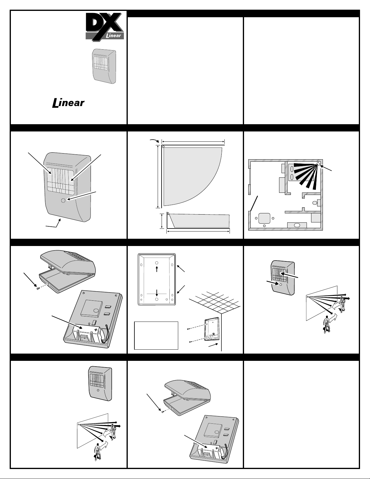
DXT-54
DON'T POINT AT HEAT SOURCES
(HEATERS, ETC.), WINDOWS, OTHER
MOTION DETECTORS OR DOOR/WINDOW
TRANSMITTERS
BEDROOM
BATH
KITCHEN
FRONT
ROOM
(FOR INDOOR
USE ONLY)
MOUNT
DETECTOR
SO THAT
INTRUDER
WILL CROSS
BEAMS
MOTION
DETECTOR
WIRELESS
MOTION
DETECTOR
Installation Instructions
(619) 438-7000 • FAX (619) 438-7043
USA & Canada (800) 421-1587 & (800) 392-0123
Toll Free FAX (800) 468-1340
DXT-54 FEATURES DETECTION PATTERN TYPICAL INSTALLATION
MOTION
DETECTOR
LENS
BY
WALK TEST
INDICATOR
(BEHIND LENS)
WALK
TEST
BUTTON
The DXT-54 is a battery powered passive infrared motion detec tor with
PRODUCT DESCRIPTION
a built-in transmitter designed for use with Linear’s DX Format
receivers. This transmitter can be used in a variety of motion detection
applications. When the passive infrared sensor detects motion in its
field of view, the transmitter sends a digitally coded wireless signal to
its companion receiver.
The digital DX code format features over a million possible codes. The
DX transmitters are precoded at the factory to unique c odes, so no field
coding is required. The DXT-54 can send two different codes: alarm
and low battery.
For versatility, any transmitter can be programmed into any receiver
channel. Receivers must be programmed to the transmitter’s code
before system testing and operation. Refer to the receiver’s
instructions for details on programming.
In a typical installation, the motion detector is mounted indoors in a
corner or on a wall between six and eight feet high. The sensor will
monitor the infrared level in its detection pattern. If the level increases
or decreases rapidly (as when a person or animal moves through the
area) the transmitter triggers, sending an alarm signal to the receiver.
MOTION
DETECTOR
IN CORNER
30 FEET
30 FEET
DETECTION
AREA
TOP
VIEW
The unit is powered from a 9-Volt alkaline battery with an expected
battery life of up to three years depending on the area’s traffic. When
the battery gets low, the test indicator will flash during motion and any
alarm transmission will also send a low battery signal to the receiver
(some receivers can report low battery, others cannot).
To conserve battery life, the detector will trigger the transmitter
only once every four minutes. When testing, remain out of the
detection area for at least five minutes before walking in front of the
unit to cause an alarm transmission.
For setup and testing, pressing the detector’s test button places the
unit in walk test mode for four minutes. The installer can walk in front
of the unit while viewing the test indicator behind the detector’s lens to
determine the detection area. In walk test, an alarm signal is sent each
time the walk test indicator lights.
CASE
LOCKING
SCREW
(ON BOTTOM)
CONNECTING BATTERY MOUNTING DETECTOR BASE WALK TEST
REMOVE
SCREW
AND OPEN
CASE
CONNECT 9-VOLT ALKALINE
BATTERY TO BATTERY CLIP
(PLUS SIDE UP)
NOTE: BE SURE TO
REPLACE THE CASE
SCREW AFTER CLOSING
THE CASE
PROGRAM RECEIVER AND TEST CHANGING BATTERY LINEAR LIMITED WARRANTY
FOR PROGRAMMING,
REFER TO THE RECEIVER'S
INSTRUCTIONS
AFTER PROGRAMMING RECEIVER
TO THE TRANSMITTER'S CODE
TEST THE SYSTEM
STAYING CLEAR, WAIT AT LEAST
FIVE MINUTES BEFORE WALKING
INTO THE DETECTION AREA
WALK ACROSS THE DETECTION
PATTERN AND VERIFY THAT
THE RECEIVER ACTIVATES
6-8 FEET
MOUNTING THE DETECTOR
IN A CORNER IS PREFERRED
USE CENTER
HOLES FOR
WALL
MOUNTING
PUNCH OUT REQUIRED HOLES
FOR SCREW MOUNTING
NOTE:
THE DETECTOR CAN
BE MOUNTED WITH
DOUBLE STICK TAPE,
BUT SCREW MOUNTING
IS PREFERRED
WHEN THE DETECTOR
HAS A LOW BATTERY:
REMOVE
SCREW
AND OPEN
CASE
REPLACE THE BATTERY WITH
A FRESH 9-VOLT ALKALINE
OR LITHIUM BATTERY
(PLUS SIDE UP)
USE ALKALINE
OR LITHIUM
BATTERIES ONLY
SNAP DETECTOR ONTO BASE
AND REPLACE CASE SCREW
WHEN FINISHED
30 FEET
AFTER MOUNTING, SNAP
DETECTOR ONTO BASE
AND REPLACE CASE SCREW
USE SIDE HOLES
FOR CORNER
MOUNTING
MOUNT
DETECTOR
6-8 FEET
HIGH
SIDE
VIEW
PUSH
WALK
TEST
BUTTON
UNIT WILL STAY IN
WALK TEST MODE
FOR 4 MINUTES AFTER
PRESSING WALK TEST
BUTTON
VERIFY THAT DETECTION
PATTERN COVERS DESIRED
AREA
This Linear product is warranted against defect s in material and workmanship for twelve (12) months. The
Warranty Expiration Date is labeled on the produc t. This warranty extends only to wholesale customers
who buy direct from Linear or through Linear’s normal dist ribution channels. Linear does not warrant
this product to consumers. Consumers should inquire from their selling dealer as to the nature of the
dealer’s warranty, if any. There are no obligations or liabilities on the part of Linear corporation for
consequential damages arising out of or in connection with use or performance of this product or
other indirect damages with respect to loss of property, revenue, or profit, or cost of removal,
installation, or reinstallation. All implied warranties, including implied warranties for merchantability and
implied warranties for fit ness, are valid only until Warranty Expirat ion Date as labeled on the product. This
Linear Corporation Warranty is in lieu of all other warranties express or implied.
For warranty service on Linear equipment return product, at sender’s expense to:
Linear Corporation Repairs Department
2580 Pioneer Avenue, Suite C
Vista, CA 92083
Linear radio controls provide a reliable communications link and fill an important need in portable wireless
signalling. However, there are some limi tations which must be observed.
For U.S. installations only: The radi os are required to comply with FCC Rules and Regulations as
Part 15 devices. As such, they hav e limited transmitter power and therefore limited range.
A receiver cannot respond to more than one transmitt ed signal at a time and may be blocked by
radio signals that occur on or near their operating fr equencies, regardless of code settings.
Changes or modifications to the device may void FCC compliance.
Infrequently used radio links should be t ested regularly to protect against undetected interference
or fault.
A general knowledge of radio and its vagaries shoul d be gained prior to acting as a wholesale
distributor or dealer, and these facts s hould be communicated to the ultimate users.
Copyright © 1995 Linear Corporation 211690 A
WALK IN FRONT OF UNIT
WHILE WATCHING RED LIGHT
NOTE: AFTER INITIAL SETUP
WALK TEST UNIT ANNUALLY
IMPORTANT !!!
 Loading...