

Page 1
DXT-31
DOOR/WINDOW
TRANSMITTER
Installation Instructions
DXT-31
TRANSMITTER
BY
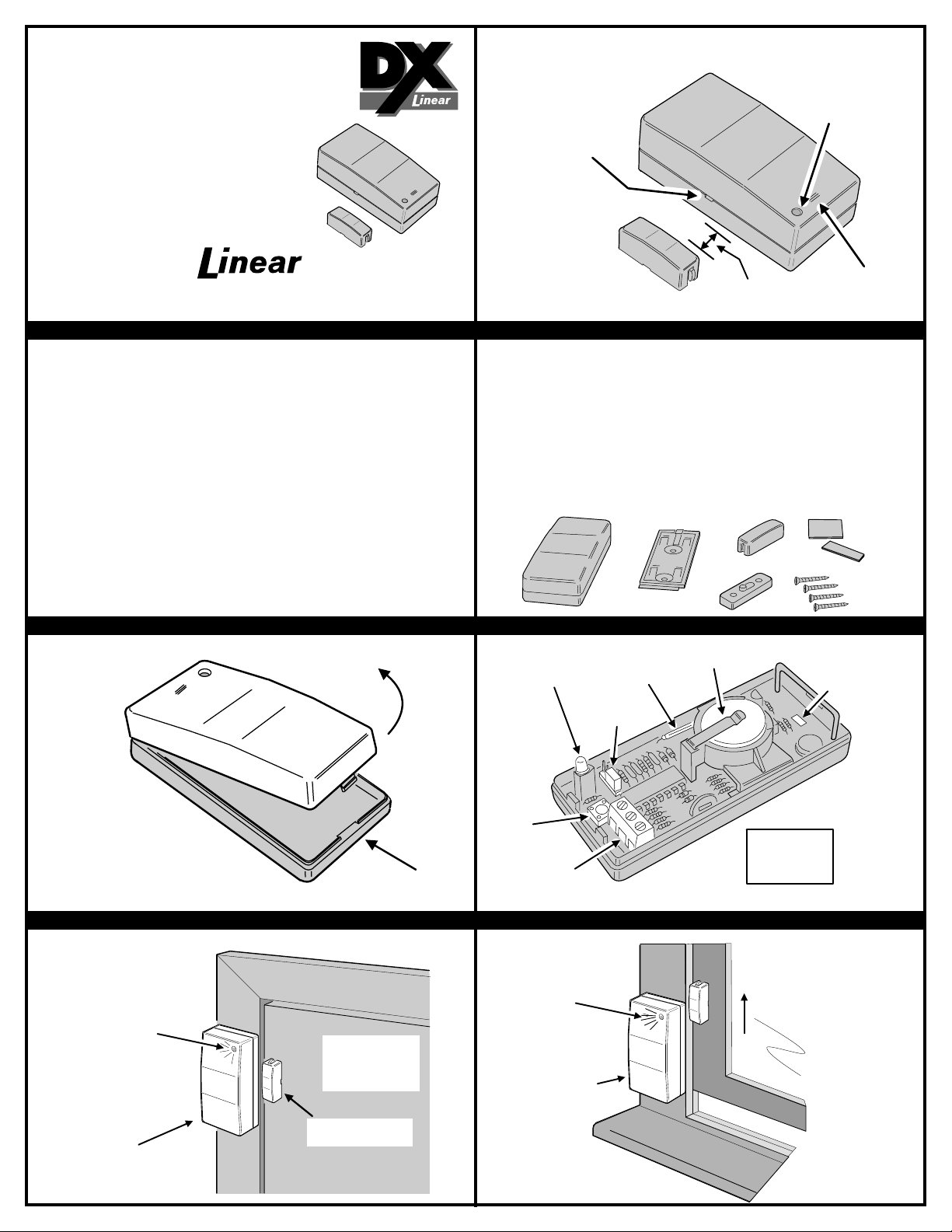
NOTCH ON SIDE OF
TRANSMITTER
ALIGN MAGNET
NEXT TO NOTCH
TEST/OPERATE
INDICATOR
(619) 438-7000 • FAX (619) 438-7043
USA & Canada (800) 421-1587 & (800) 392-0123
Toll Free FAX (800) 468-1340
DXT-31 FEATURES PRODUCT DESCRIPTION
The DXT-31 is a battery powered stationary transmitter designed for use with Linear’s DX Format
receivers. This transmitter can be used in a limitless number of wireless remote control applications.
Triggering the transmitter with its built-in magnetic switch, an external switch or an external glass
break detector sends a digitally coded wireless signal to its companion receiver. Pressing the
transmitter’s case sends a test transmission.
The digital DX code format features over a million possible codes. The DX transmitters are precoded
at the factory to unique codes, so no field coding is required. The DXT-31 can send three different
codes: alarm, restore and low battery.
For versatility, any transmitter can be programmed into any receiver channel. Receivers must be
programmed to the transmitter code before system testing and operation. Refer to the receiver’s
instructions for details on programming.
In a typical installation, the magnet is mounted on a door or window and the transmitter is mounted
on the frame. When the magnet moves more than 1/2" away from the transmitter, an alarm signal
is sent. When the magnet returns next to the unit, a restore signal is sent. Alarms and restores can
also be sent from external contacts wired to the terminal block. Pressing the case sends a test
transmission that indicates the current state of the contacts.
OPENING CASE COMPONENT LOCATIONS
OPEN
MAGNET
1/2" SPACE
MAXIMUM
PUSH CASE
TO TEST
The transmitter is powered from two 3-Volt #2032 lithium batteries with an expected battery life of
up to 3 years. The red test/operate indicator lights during operation and test. It will blink during
operation and test when the batteries are low.
A three-position terminal block is for connection to normally closed external contacts or a normally
open “Window Bug” type glass break sensor. An internal jumper selects which input to use.
Selections are: internal switch only, external switch only, both external and internal switch, and glass
break sensor.
A snap-on transmitter mounting plate is provided for easy installation. The magnet has four height
positions. An additional snap-on magnet spacer is provided for a total of eight magnet positions.
NOTE: Functioning of the slide switch marked INSTANT and DELAYED on the bottom of the
DXT-31 depends on the receiver used. With some receivers, it has no function.
TEST/OPERATION
INDICATOR
DXT-31
TRANSMITTER
INTERNAL
REED
SWITCH
OPTION
JUMPER
MOUNTING
PLATE
BATTERIES
(TYPE 2032)
ADJUSTABLE
MAGNET
MAGNET
SPACER
MOUNTING
TAPE
MOUNTING
SCREWS
PUSH SCREWDRIVER
THROUGH HOLE TO
RELEASE MOUNTING
PLATE
OPEN TRANSMITTER
TO ACCESS BATTERIES,
TERMINAL BLOCK, OPTION
JUMPER AND MOUNTING PLATE
RELEASE TAB
EXAMPLE DOOR INSTALLATION EXAMPLE WINDOW INSTALLATION
INDICATOR
LIGHTS DURING
TRANSMISSION
TRANSMITTER
MOUNTS ON
FRAME
OPENING DOOR
MOVES MAGNET
AWAY FROM
TRANSMITTER
MAGNET MOUNTS
ON DOOR
PRY
TEST
BUTTON
TERMINAL
BLOCK
INDICATOR
LIGHTS DURING
TRANSMISSION
TRANSMITTER
MOUNTS ON
FRAME
1
2
3
TERMINALS
1-EXTERNAL
2-COMMON
3-GLASS BREAK
OPENING WINDOW MOVES
MAGNET AWAY FROM
TRANSMITTER
Page 2
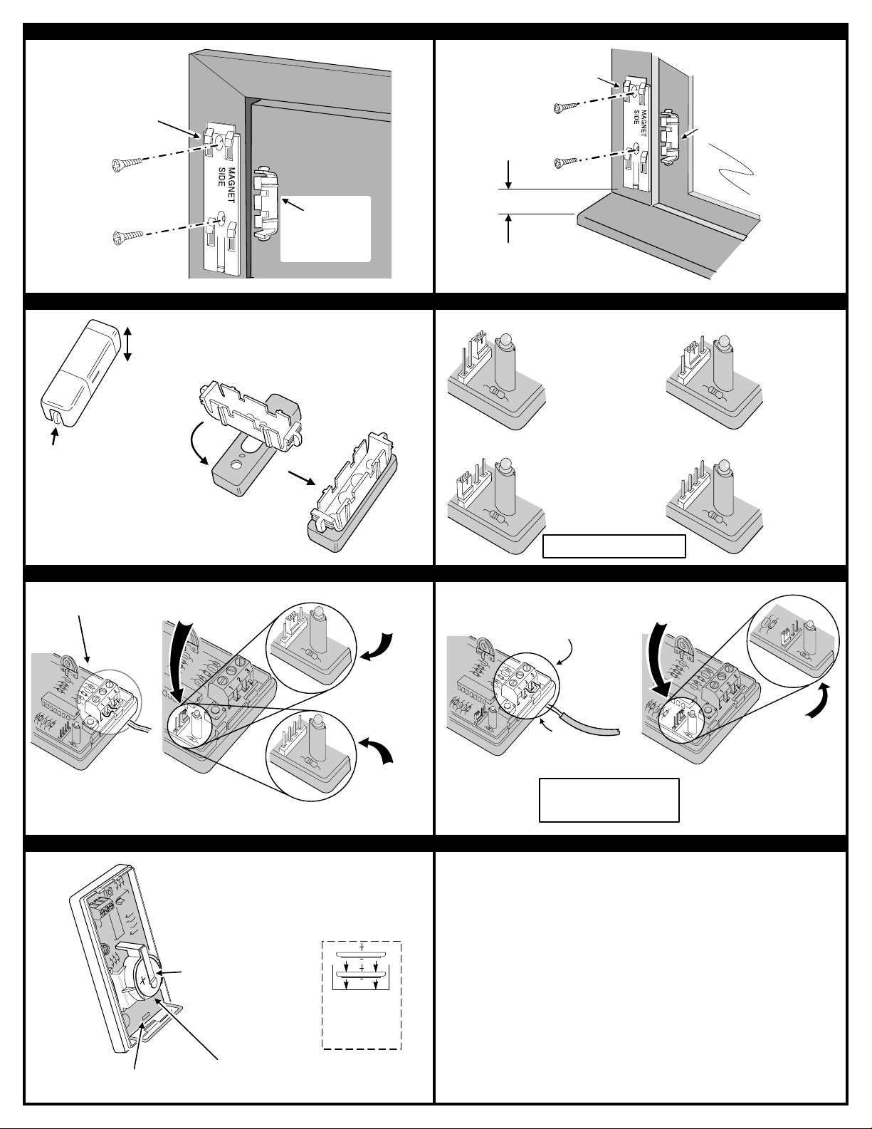
MOUNT PLATE
1/2" MINIMUM
MOUNT TRANSMITTER
PLATE TO FRAME
ALIGN MAGNET
PLATE NEXT TO
TRANSMITTER
PLATE AND ATTACH
TO WINDOW
SPACE BELOW
PLATE IS REQUIRED
TO SNAP TRANSMITTER
ONTO PLATE
SNAP TRANSMITTER
ONTO MOUNTING PLATE
TO FRAME
1/2" MAXIMUM
SPACE BETWEEN
TRANSMITTER AND
MAGNET PLATES
SNAP TRANSMITTER
ONTO MOUNTING PLATE
MOUNTING ON DOOR MOUNTING ON WINDOW
ALIGN MAGNET
PLATE NEXT TO
TRANSMITTER
PLATE AND ATTACH
TO DOOR
OPTIONAL MAGNET SPACER OPTION JUMPER POSITIONS
SQUEEZE SIDE TABS
TO ADJUST MAGNET
HEIGHT
WIRE EXTERNAL NORMALLY
CLOSED CONTACTS TO
TERMINALS 1 & 2
IF NECESSARY
PUSH IN SLOT TO REMOVE
SENSOR FROM MOUNTING PLATE
FOUR HEIGHT
POSITIONS
HOOK SPACER TO
MAGNET PLATE
AND ROTATE TO
LOCK IN PLACE
USE SNAP-ON MAGNET
SPACER WHEN MORE
HEIGHT IS REQUIRED
SELECTS INTERNAL
SWITCH
(INSIDE POSITION)
SELECTS GLASS
BREAK SENSOR ONLY
(EDGE POSITION)
NOTE: GLASS BREAK INPUT
TERMINALS ARE ALWAYS ACTIVE
SELECTS EXTERNAL
SWITCH
(MIDDLE POSITION)
SELECTS BOTH
INTERNAL AND
EXTERNAL SWITCHES
(NO JUMPER)
CONNECTING EXTERNAL CONTACTS CONNECTING EXTERNAL GLASS BREAK SENSOR
THIS IS THE FACTORY SET
JUMPER POSITION IT SELECTS
THE INTERNAL SWITCH
IMPORTANT NOTE:
WHEN USING BOTH
INTERNAL AND EXTERNAL
SWITCHES BOTH SWITCHES MUST
BE CLOSED TO ARM THE TRANSMITTER
CHANGING BATTERIES LINEAR LIMITED WARRANTY
WHEN BATTERIES ARE LOW, OPEN SENSOR CASE AND
GENTLY LIFT UP END OF BATTERY CLAMP,
SLIDE BATTERIES OUT
NOTE: USE OF EXCESSIVE FORCE ON
BATTERY CLAMP WILL RESULT IN DAMAGE
LIFT
REMOVE BATTERIES
FROM THIS END
PUT JUMPER
ON THE MIDDLE
PINS TO USE
EXTERNAL
SWITCH
- OR -
TAKE JUMPER
OFF TO USE
BOTH
EXTERNAL
& INTERNAL
SWITCH
INSTALL TWO
DURACELL
TYPE DL 2032
BATTERIES (+)
SIDE UP
MOVE JUMPER FROM
THESE PINS (SELECTS
CONNECT NORMALLY OPEN
GLASS BREAK SENSOR
WIRES TO TERMINALS 2 & 3
ROUTE SENSOR
WIRES UP THROUGH
WIRING SLOT
NOTE: THIS TRANSMITTER IS DESIGNED
FOR USE WITH THE UNITED SECURITY
PRODUCTS "WINDOW BUG" GLASS
BREAK SENSOR. OTHER SENSORS
HAVE NOT BEEN TESTED.
This Linear product is warranted against defects in material and workmanship for twelve (12) months. The Warranty Expiration Date
is labeled on the product. This warranty extends only to wholesale customers who buy direct from Linear or through Linear’s
normal distribution channels. Linear does not warrant this product to consumers. Consumers should inquire from their selling
dealer as to the nature of the dealer’s warranty, if any. There are no obligations or liabilities on the part of Linear corpo ration
for consequential damages arising out of or in connection with use or performance of this product or other indirect damages
with respect to loss of property, revenue, or profit, or cost of removal, installation, or reinstallation. All implied warranties,
including implied warranties for merchantability and implied warranties for fitness, are valid only until Warranty Expiration Date as
labeled on the product. This Linear Corporation Warranty is in lieu of all other warranties express or implied.
For warranty service on Linear equipment return product, at sender’s expense to:
Linear Corporation Repairs Department
2580 Pioneer Avenue, Suite C
Vista, CA 92083
Linear radio controls provide a reliable communications link and fill an important need in portable wireless signalling. However, there
are some limitations which must be observed.
For U.S. installations only: The radios are required to comply with FCC Rules and Regulations as Part 15 devices. As such,
they have limited transmitter power and therefore limited range.
A receiver cannot respond to more than one transmitted signal at a time and may be blocked by radio signals that occur on or
near their operating frequencies, regardless of code settings.
Changes or modifications to the device may void FCC compliance.
Infrequently used radio links should be tested regularly to protect against undetected interference or fault.
A general knowledge of radio and its vagaries should be gained prior to acting as a wholesale distributor or dealer, and these
facts should be communicated to the ultimate users.
Copyright © 1995 Linear Corporation 211694 A
INTERNAL SWITCH)
IMPORTANT !!!
TO THESE PINS
(SELECTS GLASS
BREAK SENSOR)
 Loading...