

Page 1
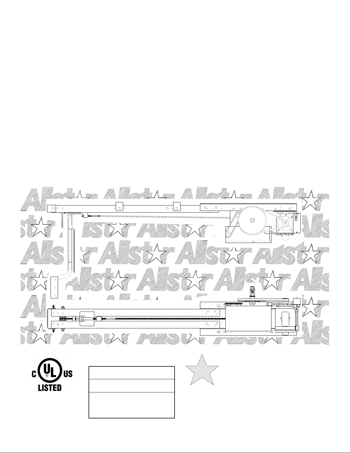
INSTALLATION AND
OWNER’S MANUAL
AUD
ADVANCED U-SERIES DRAWBAR COMMERCIAL
VEHICULAR DOOR OPERATORS
107093
As of date of manufacture,
meets all ANSI/UL 325
Safety Requirements for
Vehicular door operators
Serial #:
Date Installed:
Your Dealer:
READ THIS MANUAL
CAREFULLY BEFORE
INSTALLATION OR USE
SAVE THESE INSTRUCTIONS !
Page 2
TABLE OF CONTENTS
Model AUD Drawbar Operator Features & Applications ......................................... 3
Preparation................................................................................................................. 4
Figure 1 - Component Identification Pictorial.......................................................... 4
Important Installation Warnings (Things To Do Before & During Installation)...... 5
Table 1 - Component Identification Listing.............................................................. 5
Rail/Chain Assembly Instructions ............................................................................ 6
Installation Instructions........................................................................................ 7-10
Section C: Installing the Operator ........................................................................... 9
Setting The Limits.................................................................................................... 10
Electrical Wiring Instructions.................................................................................. 11
Figure 16 - Pneumatic Door Edge Installation ....................................................... 12
Figure 17 - Field Wiring ........................................................................................... 12
Operation and Adjustment Instructions ............................................................ 13-17
Important Safety Instructions for Owner................................................................ 13
Wiring Terms............................................................................................................ 13
Wiring Types ............................................................................................................ 14
Clutch Adjustment ................................................................................................... 15
Brake Adjustment .................................................................................................... 16
Testing...................................................................................................................... 16
Maintenance ............................................................................................................ 17
Figure 20 - Operator Dimensions............................................................................ 17
Wiring Diagrams/Schematics (Single & Three Phase) ..................................... 18-19
Warranty ................................................................................................................... 20
2
READ THESE STATEMENTS CAREFULLY AND FOLLOW THE
The Warning and Caution boxes throughout this manual are there to protect you and
your equipment. Pay close attention to these boxes as you follow the manual.
WARNING
Indicates a MECHANICAL
hazard of INJURY OR
DEATH. Gives instructions
to avoid the hazard.
INSTRUCTIONS CLOSELY.
CAUTION
Indicates a MECHANICAL hazard
of DAMAGE to your operator or
equipment. Gives instructions to
avoid the hazard.
WARNING
Indicates an ELECTRICAL
hazard of INJURY OR
DEATH. Gives instructions
to avoid the hazard.
CAUTION
Indicates an ELECTRICAL hazard
of DAMAGE to your operator or
equipment. Gives instructions to
avoid the hazard.
Page 3

3
PRODUCT FEATURES
The purpose of this booklet is to provide assembly,
installation and operation information concerning Allstar
Model AUD Commercial Vehicular Garage Door Operators
and related Accessory Products.
NOTICE
IT IS IMPORTANT THAT THIS INSTRUCTION
MANUAL BE READ AND UNDERSTOOD
COMPLETELY BEFORE INSTALLATION OR
OPERATION IS ATTEMPTED. IT IS
INTENDED THAT THE INSTALLATION OF
THIS UNIT WILL BE DONE ONLY BY
PERSONS TRAINED AND QUALIFIED IN
THE INSTALLATION, ADJUSTMENT AND
SERVICE OF COMMERCIAL OVERHEAD
DOORS AND DOOR OPERATORS AND BY
QUALIFIED ELECTRICIANS.
NOTICE
THE IMPORTANT SAFEGUARDS AND
INSTRUCTIONS IN THIS MANUAL CANNOT
COVER ALL POSSIBLE CONDITIONS AND
SITUATIONS WHICH MAY OCCUR DURING
ITS USE. IT MUST BE UNDERSTOOD THAT
COMMON SENSE AND CAUTION MUST BE
EXERCISED BY THE PERSON(S) INSTAL-
LING, MAINTAINING AND OPERATING THE
EQUIPMENT DESCRIBED HEREIN. DO NOT
USE THIS EQUIPMENT FOR ANY OTHER
THAN ITS INTENDED
PURPOSE - OPERATING OVERHEAD
COMMERCIAL VEHICULAR GARAGE
DOORS.
MODEL AUD OPERATOR APPLICATIONS:
Drawbar operators are for commercial and industrial use
on sectional overhead doors which use horizontal track
with normal radius. A draw bar operator is not suitable for
doors with high lift exceeding 24 inches or vertical lift
doors. The installation requires a minimum clearance of 5
inches above the high arc of the door (the highest point
reached by the door at any part of its travel). For backroom requirement refer to Figure 20, Page 17. When
properly installed a drawbar operator effectively locks the
door in the closed position.
The Model AUD drawbar operators are used in the
following applications:
-Continuous Duty, Medium Cycle Commercial
installations only
-Indoor Use Only
-Up to 22 foot high doors with a maximum area of 480
square feet for 3/4 HP, 280 square feet for 1/2 HP and
200 square feet for 1/3 HP - maximum area slightly
higher for lighter doors - consult factory
-Use with foam or pneumatic reversing edge door
components - REQUIRED where the 3 button station is
out of sight of the door or any other automatic, remote
or manual control is used to activate the door.
STANDARD FEATURES:
Limit Switches: Driven limit switches, easily adjusted over
a wide range. The motor may be removed without affecting
the limit switch adjustments
Manual Release: Permits manual operation of the door in
the event of a power failure.
Control Circuit: Standard three button open, close and stop.
24 Volts AC.
Connections For Auxiliary Entrapment Protection
Devices:
components or a photoelectric beam (across the opening)
devise.
Constant Contact To Close: Feature can be activated by
simply moving a wire on the terminal strip.
Momentary Contact To Open and Close: Standard
operation.
Use with foam or pneumatic reversing door edge
OPTIONAL FEATURES:
Digital Radio Controls: Open, Close and Stop operation.
Radio units are available to control up to 27 doors from one
transmitter
Digital Timer to Close: Adjustable from 0 to 17 minutes
in one second intervals.
Keyless Entry System: Connection terminals provided for
hard wired or wireless keyless entry system.
Brake: Optional on 1/3 & 1/2HP, Standard on 3/4 &
1HP.
Can be added in the field.
Page 4
PREPARATION
WARNING
ELECTRIC DOOR OPENERS ARE DESIGNED
FOR DOORS IN GOOD WORKING CONDITION,
PROPERLY COUNTERBALANCED AND
PROPERLY ADJUSTED IN ACCORDANCE WITH
THE DOOR MANUFACTURER'S INSTALLATION
INSTRUCTIONS.
Before starting the installation of the operator, the door must be in
good working condition and properly counterbalanced. Inspect the
door and track for loose or missing hardware. Test the door
manually for balance and ease of operation. Lubricate door hinges
and rollers. If necessary, adjust the springs for proper
counterbalance of the door.
Before removing the operator powerhead from the shipping carton,
inspect the nameplate on the cover of the operator control box to
verify that it is the correct model for the intended application and
that the voltage and phase are in accordance with electrical power
provided at the job site.
4
The rails and drawbar chain/hardware package are shipped
separately from the powerhead. Warning: Rope off the area
to keep personnel and vehicles clear of the door and floor
space in the vicinity of the operator during the
installation.
WARNING
SPRINGS ARE SUBJECT TO VERY
HIGH FORCES AT ALL TIMES AND
ADJUSTMENTS MUST BE MADE ONLY
BY A QUALIFIED PROFESSIONAL
DOOR INSTALLER.
WARNING
REMOVE OR DISABLE ANY LOCKING
DEVICES FROM DOOR AND REMOVE
ALL ROPES
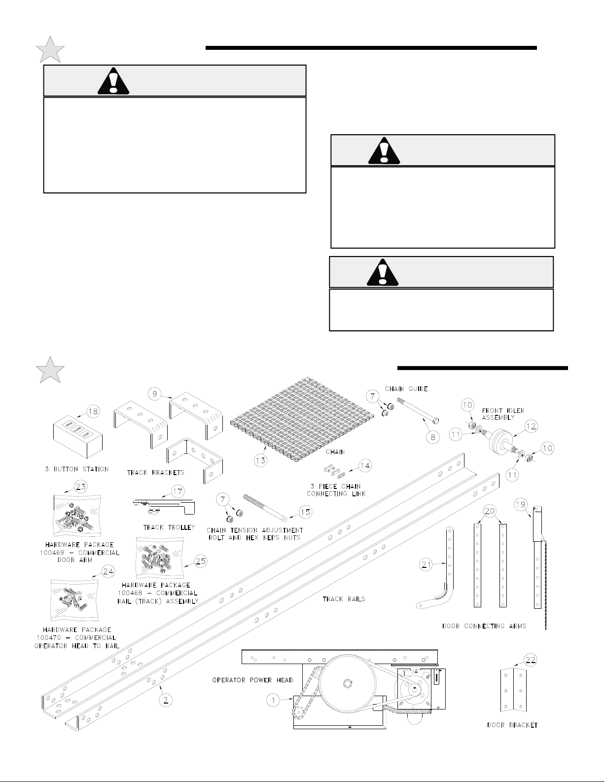
COMPONENT IDENTIFICATION PICTORIAL
107100
Page 5
5
WARNING
IMPORTANT INSTALLATION NOTES
TO REDUCE THE RISK OF SEVERE INJURY
OR DEATH: READ AND FOLLOW ALL
INSTALLATION INSTRUCTIONS!
• Install only on a properly balanced garage
door. An improperly balanced door could cause
severe injury. Have a qualified service person
make repairs to cables, spring assemblies and
other hardware before installing the opener.
• Remove all ropes and remove or make
inoperative all locks (unless mechanically and/or
electrically interlocked to the power unit) that are
connected to the garage door before installing the
opener.
• Lightweight doors (fiberglass, aluminum etc.)
must be reinforced to avoid door damage. Check
the door manufacturer’s instruction manual for a
bracing procedure or the availability or a
Reinforcement Kit. See Page 9.
• Allstar Model AUD is a Commercial
Vehicular Door Operator and as such IS NOT
recommended for pedestrian traffic. In
installations where it is known that pedestrians
will be nearby ensure a pedestrian door is
available for entrance and exit to the building. In
addition YOU MUST install an auxiliary
entrapment protection device (reversing door edge
or photoelectric beam device).
• Connect an auxiliary entrapment protection
device (reversing edge or photoelectric device
across the door opening). a device of this type is
STRONGLY ADVISED FOR ALL commercial
operator installations. An auxiliary entrapment
protection device is REQUIRED when the three
button control station is out of sight of the door
or any other automatic or manual control is
used.
• Install the opener at least 8 feet or more
above the floor.
• Do not connect the opener to the source of
power until instructed to do so.
• Locate the control station:
a) within sight of the door and;
b) at a minimum height of five feet above
the floor and;
c) away from all moving parts of the door.
• Do not overtighten the clutch adjustment to
compensate for a poorly working door.
• Securely attach any WARNING signs or
placards to either the door or above the control
station as directed (see page 11).
• After installing the opener, all safety features
must be tested for proper operation (see page
16).
COMPONENT IDENTIFICATION LISTING
ITEM # PART# DESCRIPTION QUAN.
1 Operator Power Head 1
2 Track Rails 2
7 006031 3/8-16 Keps Hex Nut 6
8 101315 3/8 - 16 X 6-1/2 Hex Head Blot 1
9 107049 Track Bracket AR
10 006034 1/2 - 15 Hex Nut 2
11 006049 1/2 Split Lockwasher 2
12 106265 Front Idler Assembly 1
13 Chain For Track Rail 1
14 3 Piece Chain Connecting Link 1
15 006084 Chain Tension Adjustment Bolt 1
16 006031 3/8 - 16 Keps Hex Nut 2
17 100512 Track Trolley 1
—— AR - As Required
ITEM # PART# DESCRIPTION QUAN
18 005031 3 Button Station 1
19 100513 Release Door Arm 1
20 100236 Extension Door Arm 2
21 100235 Curved Door Arm 1
22 100108 Door Bracket 1
23 100469 Hardware Pkg Com. Door Arm 1
26 3/8 - 16 X 2-1/2 Carriage Bolt 2
16 3/8 - 16 X 1 Hex Head Bolt 1
27 3/8 Nylon Insert Locknut 1
28 5/16 - 18 X 1-1/4 Hex Head Bolt 4
29 5/16 - 18 Keps Hex Nuts 4
25 100468 Hardware Pkg Com. Track Assy 1
4 3/8 - 16 Hex Nut AR
5 3/8 Split Lockwasher AR
6 3/8 - 16 X 1-1/2 Hex Head Bolt AR
Page 6
RAIL/CHAIN ASSEMBLY INSTRUCTIONS
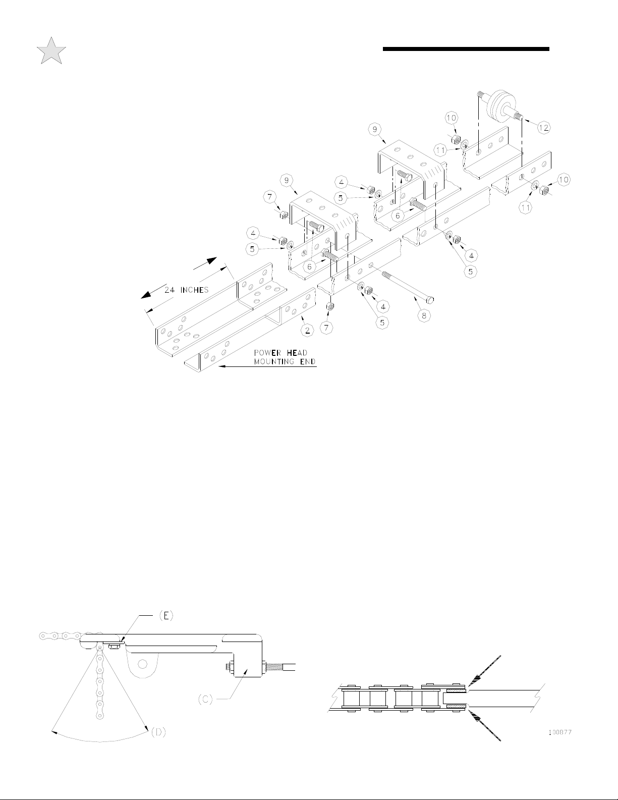
RAIL/CHAIN ASSEMBLY
Refer to Figure 1 parts illustrations. The part names and item numbers are
referenced identically to the part names and numbers in the assembly procedures
that follow. Before starting assembly of the operator track check for the
proper length. The tracks are supplied for 8 Foot, 10/12/14 Foot,
16/18 Foot and 20/22 Foot high doors. The tracks should be
three (3) feet longer than the door height. If the tracks
supplied with the operator are longer than the door
height plus 3 feet, it will be necessary to cut off two
feet (or 4 feet for 10 Foot rail) from the power head
mounting end as shown in Figure 2.
CAUTION
CUT THE TRACK ENSURE THE
ENDS ARE LINED UP AS IN
FIGURE 2.
1) Assemble the
operator track by
assembling the items
as shown in Figure 2.
2) After the track is assembled, position track assembly onto
the operator power head and attach with four 3/8”-16 x 1” bolts,
lock washers and nuts (supplied in a separate hardware package
#100470).
3) Referring to Figure 1 , 2 and 3 (below) , slide the trolley
onto the track with the chain take up bolt lug (C) toward the
power head. Thread one 3/8-16 keps nut (attached star washer)
onto the Chain take up bolt with the keps part (attached star
washer) away from the chain attachment end. Insert the chain
take up bolt threaded end through the lug hole on the trolley (C)
just far enough to start a second 3/8-16 keps nut. Attach one end
of the chain to the opposite end of the threaded stud using a 3piece chain link (provided). See Figure 3.
: WHEN NECESSARY TO
48” FOR 10FT RAIL
107068
the connecting link. One-third horsepower operators use the
narrower #65 chain and the use of the spacers is not required.
Install chain around drive sprocket at operator head then around
idler at front end of rail and thread through opening at front end
of carrier. If the rail is equipped with a chain guide-spacer near
its center (12 foot rail or longer only) pass the chain over it in one
direction and under it in the other direction to separate the two
lengths of chain. Apply initial tension by pushing forward on the
carrier while pulling chain tight through opening in the carrier in
the direction of D. When maximum tension has been applied by
this means, swing chain forward and insert retaining plate, E, in
place. Insert 1/4-20 x 5/8 hex head machine screw through
retaining plate, E, and tighten plate in place. Make final
adjustment of chain tension to remove excess sag by adjusting
nuts on threaded rod at chain lug, C.
6
Figure 2
NOTE: To keep #41 chain (used
on 1/2 and 3/4 H.P. operators) centered
on the threaded stud, place a .065" thick flat
washer (provided) on each side of the flat, as
indicated by the arrows in Figure 4, when installing
100461
Figure 3
Figure 4
Page 7

7
INSTALLATION INSTRUCTIONS
TO AVOID DAMAGE TO DOOR AND OPERATOR
ENSURE ALL DOOR LOCKS ARE DISABLED.
USE AN INTERLOCK SWITCH IF A LOCK IS
REQUIRED TO RETAIN FUNCTIONALITY.
1) Locate the center of the door and mark a line on the wall
directly above the door. Extend this line approximately 20” up
the wall. See Figure 5.
CAUTION
107094
A MINIMUM OF TWO PERSONS ARE
REQUIRED FOR OPERATOR
3) Using the projected lines for location, mount a suitable
wood block or angle iron, depending on the structure of the
building, to the wall above the door opening as shown in Figure
7. Ensure the block or angle iron used will provide a sound and
secure mounting pad for the operator rail front mounting bracket,
see CAUTION warning below.
ENSURE A SAFE RIGID WORKING
PLATFORM IS AVAILABLE.
CAUTION
INSTALLATION.
107096
Figure 5
2) Slowly raise the garage door and observe the action of the
top section. When the top section reaches the highest point
(high arc), use a level and project a line from this point to the
center of the door. See Figure 6.
107095
Figure 6
Figure 7
THE FRONT MOUNTING SURFACE FOR THE
OPERATOR MUST BE SOUND AND SECURE.
IF NECESSARY PROVIDE REINFORCEMENT
IN THIS AREA BEFORE MOUNTING THE
OPERATOR RAIL FRONT MOUNTING
CAUTION
BRACKET.
Page 8

INSTALLATION INSTRUCTIONS
8
4)
Mount the front mounting bracket (Item 9) to the mounting
pad as shown in Figure 8. The location of the door’s torsion
shaft may prevent you from placing the mounting pad in the
location shown. Mount the pad as close as possible to three (3)
107051
6) Swing the operator to a horizontal position above the door
guide rails (high enough to raise the door) and temporarily
secure by suspending from the ceiling with a suitable rope or
chain or support from the floor to the operator. Now open the
garage door slowly, being careful not to dislodge the temporary
support. Lower the operator until it is level. Make sure the
operator is aligned with the center of the door and the bottom of
the rail is at least 2” above the high arc of the door. See Figure
10.
WARNING
FAILURE TO SUSPEND THE OPERATOR
SECURELY MAY RESULT IN SERIOUS
PERSONAL INJURY OR DEATH.
Figure 8
5) With the door in the down position, loosely attach the rail
support to the mounting bracket using two (2) bolts, lockwashers
and nuts (Items 4, 5, 6). See Figure 9.
107053
Figure 9
SPRINGS, PULLEYS, CABLES AND MOUNTING HARDWARE USED TO
BALANCE YOUR GARAGE DOOR ARE UNDER EXTREME TENSION AT
ALL TIMES AND CAN CAUSE SEVERE INJURY OR DEATH IF DISTURBED.
WARNING
DO NOT ATTEMPT ADJUSTMENT.
107052
Figure 10
7) Tighten securely the two (2) bolts, nuts and washers that
were loosely attached in Step 5. See Figure 11.
107054
Figure 11
Page 9

9
INSTALLATION INSTRUCTIONS
8) Figure 12 details a typical method of hanging the operator
from the ceiling. Each installation will vary due to the
difference in building structures; but in all installations side
braces should be used to further strengthen the installation. If
the operator track (rail) is longer than 15 feet a mid support is
recommended.
107141
107142
Figure 12
9) Fully close the door and move the trolley to within 2
inches of the idler sprocket. Using Figure 13 as a guide,
connect the release arm (Item 19) to the trolley. Connect the
two extension arms (Item 20) and the door curved arm (Item 21)
to the door release arm with 5/16 inch bolts and keps nuts
(Items 28 & 29).
10) Refer to Figure 14. Attach the door bracket (Item 22) to
the curved arm using a 3/8 bolt and locknut (Items 16 & 27).
Tighten the bolt until snug then back off 1/4 to 1/2 turns so as to
allow the arm to pivot on the bolt freely. Position the door
bracket to the scribed center line on the door. Use suitable
hardware to attach the door bracket to the door.
IMPORTANT
TO AVOID DAMAGE TO THE DOOR TOP
SECTION REINFORCE THE CENTER STILE
WITH A VERTICAL BRACE. ADDITIONAL
BRACING/REINFORCEMENT MAY BE
REQUIRED WHEN THE DOOR IS
CONTROLLED BY AN AUTOMATIC DOOR
OPERATOR; CONSULT THE DOOR
MANUFACTURER FOR INSTRUCTIONS.
Figure 13
107143
Figure 14
NOTE
BEFORE PROCEEDING RECHECK ALL
BOLTS, NUTS AND LAG SCREWS AND
ENSURE THEY ARE TIGHT.
Page 10

INSTALLATION INSTRUCTIONS
10
WARNING
TO AVOID RISK OF ENTRAPMENT AND
POSSIBLE DAMAGE TO THE DOOR AND
OPERATOR THE LIMITS MUST BE ADJUSTED
BEFORE APPLYING POWER TO THE
OPERATOR.
SETTING THE LIMIT SWITCHES
1) With the cover open on the electrical enclosure, reference
Figure 6 below. There are four (4) switches (A, B, C, and D)
mounted to the ‘V’ bracket (H). The limit switches are mounted
in a fixed position to the underside of the ‘V’ bracket; with the
Close Limit switch (B) on the right and the Open Limit switch (D)
on the left. The Reverse Cutout switch (A) and the Single Button
Selector switch (C, also could be Timer Engage switch depending
on the model) are mounted to the top side of the ‘V’ bracket as
shown. The switches are activated by the two limit nuts (E & G)
on the threaded shaft which move laterally along the shaft as the
operator opens and closes the door. When a limit nut nears the
end of the shaft it activates a set of switches, upper switch first
then the lower fixed limit switch.
2) If the door and operator trolley are at the
fully closed position (original installation), set
the Close limit as described in Step 5 and, as
described below, only move the Open Limit
Nut to the center of the threads.
Otherwise, depress the Limit Nut
Retention Plate (F) so it disengages
from the slots in the limit nuts and
move the Limit nuts to the center of
the threaded shaft.
C E
4) Depress the limit nut retaining bracket (F) so it disengages
from the slots in the limit nuts. Turn the OPEN limit nut (E) on
the shaft until it engages both the Single Button Selector switch
(C) and the Open Limit Switch (D). You will need to listen for
two audible clicks. Release the retaining bracket and be sure
that it engages in slots of both limit nuts.
5) Employing the operator’s large 8” pulley, manually lower
the door to the fully closed position and repeat Step #3 with the
Close Limit nut (G) and Reverse Cutout switch (A) and the
Close Limit switch (B).
6) Manually move the door to a half open position. With the
door in a mid position there will be time to stop the door if
something or someone were in the door path when initially
starting the door.
7) A final limit adjustment will be necessary after the
connection of the power supply in order to ensure the door stops
at the proper Open and Close positions.
Adjustment of the Reverse Cutout switch (A) or Single
Button Selector switch (C) is done at the factory and should not
be needed in the field. Moving the Reverse Cutout switch
closer to the center of the box will increase the point where the
reversing feature cuts out (to allow for irregularity in the floor,
etc.). The reverse cutout point is factory adjusted to approx. 4
inches off the floor.
F
107102
G
A
3) Employing the operator’s
large 8” pulley, manually raise the
door to a nearly open position.
Figure 15
Limit Assembly
A - REVERSE CUTOUT SWITCH
(LS4, ADJUSTABLE)
B - CLOSE LIMIT SWITCH
(LS2, FIXED POSITION)
C - SINGLE BUTTON SELECTOR
or TIMER ENGAGE SWITCH
(LS3, ADJUSTABLE)
D - OPEN LIMIT SWITCH
(LS1, FIXED POSITION)
E - OPEN LIMIT NUT
F - LIMIT NUT RETAINING BRCKT
G - CLOSE LIMIT NUT
H - “V” BRACKET
D
B
H
Page 11

11
ELECTRICAL WIRING INSTRUCTIONS
WARNING
TO PREVENT THE RISK OF PERSONAL INJURY
OR DEATH :
• DISCONNECT POWER AT THE FUSE BOX
BEFORE PROCEEDING.
• ELECTRICAL CONNECTIONS MUST BE MADE
BY A QUALIFIED INDIVIDUAL.
• OBSERVE LOCAL ELECTRICAL CODES WHEN
WIRING THE OPERATOR.
WARNING: Allstar's AU Series operators have been designed
and constructed for use with voltages from 115 Volts AC to 480
Volts AC, in single or three phase. Check the operator
nameplate label on the control box cover for the proper voltage
and phase. The application of an improper input voltage or
phase will result in catastrophic failure to the internal
electrical components.
Observe local electrical codes when wiring the operator.
When hard wiring, observe state and local electrical codes. A
wiring diagram is attached to the inside of the control box cover.
Connect the appropriate voltage and phase power leads to the
appropriate terminals as per the wiring diagram and connect a
ground wire to the grounding screw. On three phase units,
incorrect phasing of the power supply will cause the motor to
rotate in the wrong direction (open when CLOSE button is pushed
and vice versa). To correct this, interchange any two of the
incoming three phase conductors.
The wiring diagram attached inside the cover of the control box
details all of the field wiring terminal connections for the operator.
Always connect the wires to the push-button controls and auxiliary
devices exactly as shown.
Warning: Control voltage of the operator is 24 volts AC, class
2. Do not run the power leads and control circuit wiring in the
same electrical conduit.
Note: Most AU Series operators are pre-wired for door
WARNING
WARNING
RISK OF ENTRAPMENT THAT MAY
RESULT IN SERIOUS PERSONAL INJURY
OR DEATH. DISCONNECT POWER TO
THE OPENER BEFORE AND DURING
INSTALLATION OF AN ACCESSORY
REVERSING DOOR EDGE OR
PHOTOELECTRIC DEVICE. DO NOT
RECONNECT POWER TO OPENER UNTIL
INSTRUCTED TO DO SO. ENSURE
DOORWAY IS CLEAR BEFORE STARTING
TESTING OF UNIT.
reversing edge components. To comply with code
requirements, the door reversing edge components must be
installed and wired to the operator. Refer to Figure 16 and
17 for Edge component installation and wiring.
For operator models not equipped with reversing edge
components ONLY ONE THREE BUTTON WALL
STATION AND NO OTHER MEANS OF CONTROL may
be used to control the operator. This is to comply with safety
requirements. In this case the pushbutton station must be located
WITHIN CLEAR SIGHT OF THE DOOR adjacent to a
placard (supplied with the operator) with this wording:
WARNING
TO PREVENT ENTRAPMENT
DO NOT START DOOR DOWNWARD
UNLESS DOOR WAY IS CLEAR
Operators which are equipped with a reversing edge circuit may
have one or more additional means of control which should be
wired in accordance with the diagram supplied in the operator.
To add a second three button station, refer to Figure 17.
Number 18 gauge wire or heavier must be used for wiring
the control stations and auxiliary control devices to the
operator. Smaller gauge wire may cause operational
problems, especially when multiple push-button stations are
used or during summer months.
TO PREVENT THE RISK OF PERSONAL
INJURY AND/OR DAMAGE TO DOOR OR
PROPERTY, ONLY OPERATE DOOR
CONTROL WHEN DOOR IS IN CLEAR VIEW.
IF CONTROL STATION CANNOT BE
LOCATED WHERE THE DOOR IS VISIBLE
OR IF ANY OTHER DEVICE IS USED TO
CONTROL THE DOOR AN AUXILIARY
ENTRAPMENT DEVISE (DOOR EDGE OR
PHOTOELECTRIC) MUST BE CONNECTED.
CAUTION
TO AVOID DAMAGE TO DOOR AND OPERATOR
ENSURE ALL DOOR LOCKS ARE DISABLED.
USE AN INTERLOCK SWITCH IF A LOCK IS
REQUIRED TO RETAIN FUNCTIONALITY.
Page 12

PNEUMATIC DOOR EDGE INSTALLATION - FIELD WIRING
12
Figure 16
Figure 17
Page 13

13
OPERATION & ADJUSTMENT INSTRUCTIONS
IMPORTANT SAFETY INSTRUCTIONS FOR OWNER
TO REDUCE THE RISK OF SEVERE INJURY OR
WARNING
• NEVER let children operate or play with door controls. Keep the Remote Control away from
children.
• ALWAYS keep a moving door in sight and keep people and objects away from the door area
until the door is completely closed. NO ONE SHOULD CROSS THE PATH OF A MOVING
DOOR.
• TEST THE DOOR OPENER’S REVERSING FEATURE (where applicable) MONTHLY. The
door MUST reverse upon contact with a 4” high object on the floor. After adjusting the
force setting (clutch) or the limit of travel, ALWAYS RETEST the Opener. Failure to ADJUST
THE OPENER PROPERLY may result in SERIOUS INJURY OR DEATH.
• DO NOT over adjust the force setting (clutch) to compensate for a poorly working door. See
page 16 for procedure to check the door operation and page 15 for proper clutch
adjustment.
• If possible, USE THE MANUAL RELEASE only when the door is closed. Use caution when
using the Release with the door open. WEAK OR BROKEN SPRINGS MAY ALLOW THE
DOOR TO CLOSE RAPIDLY, CAUSING SEVERE INJURY OR DEATH.
• KEEP THE GARAGE DOOR PROPERLY BALANCED. See the door owner's manual. An
improperly balanced door MAY CAUSE SEVERE INJURY OR DEATH. Have a QUALIFIED
SERVICE PERSON MAKE REPAIRS TO CABLES, SPRING ASSEMBLIES AND OTHER
HARDWARE. SAVE THIS INSTRUCTION MANUAL FOR END USER
DEATH: READ AND FOLLOW ALL INSTRUCTIONS!
NOTE: It is now necessary to turn on the power in
order to run the Opener to check for proper operation
and limit settings. Before doing so, ensure that all mounting
hardware is installed and has been properly tightened, that all
electrical connections are per local code requirements, and that
proper wiring practices have been followed. Also, double-check
that all ropes have been removed from the door and that the
doorway is clear.
WARNING
AVOID ELECTROCUTION:
DO NOT ROUTE LOW VOLTAGE WIRES IN
SAME CONDUIT AS HIGH VOLTAGE
WIRES. FOLLOW ALL LOCAL
ELECTRICAL CODES OR THE NATIONAL
ELECTRICAL CODE.
WARNING
FAILURE TO TEST REVERSING
SYSTEM COULD RESULT IN DEATH
OR SERIOUS INJURY. TEST THIS
SYSTEM ONCE A MONTH.
WIRING TERMS
MOMENTARY CONTACT: Button can be pushed and
then released and door will keep moving or stop without
maintaining pressure on the button.
CONSTANT PRESSURE: Constant pressure is required
on the button in order for continued door movement. When
the button is released the door will stop and possibly
reverse to full open depending on wiring type.
DOOR EDGE/PHOTOELECTRIC INPUT: The
operator wiring provides for input from an optional
pneumatic or electric door bottom edge or photoelectric
device that will cause a closing door to stop and may
reverse it to open depending on the wiring type.
OPEN OVERRIDE: When the door is closing a
momentary push of the OPEN button will reverse the door
to open.
Page 14

OPERATION & ADJUSTMENT INSTRUCTIONS
WIRING TYPES
14
NOTE: Check the marking on the operator outer carton and the
wiring diagram on the inside control box cover for the wiring
type.
B WIRING
To Open - Momentary Contact
To Close - Momentary Contact
To Stop- Momentary Contact
B1 WIRING
To Open - Momentary Contact
To Close - Momentary Contact
To Stop- Momentary Contact
Door Edge/Photoelectric Input will stop the door when closing.
B2 WIRING
To Open - Momentary Contact
To Close - Momentary Contact
To Stop- Momentary Contact
Open Override- Standard
Door Edge/Photoelectric Input will reverse a closing door to
full open - door can be stopped with the STOP button at all times.
Single Button Radio Control Input will open or close door and
reverse to open if closing but will not stop the door.
C WIRING
To Open - Momentary Contact
To Close - Constant Pressure:
Door will stop if pressure is released from CLOSE button
To Stop- Momentary Contact
C1 WIRING
To Open - Momentary Contact
To Close - Constant Pressure:
Door will stop if pressure is released from CLOSE button
To Stop- Momentary Contact
Door Edge/Photoelectric Input will stop the door when closing.
D WIRING - 2 Button Control
To Open - Momentary Contact
To Close - Constant Pressure
To Stop- Door will stop if pressure is released or when the
opener activates a limit switch at full open or full closed.
E WIRING - 2 Button Control
To Open - Momentary Contact
To Close - Constant Pressure:
If pressure is released door will reverse to full open
To Stop- Door will stop when the opener activates a limit switch
at full open or full closed. Door cannot be stopped in mid
travel.
E2 WIRING -2 Button Control
To Open - Momentary Contact
To Close - Constant Pressure:
If pressure is released door will reverse to full open
To Stop- Door will stop when the opener activates a limit switch
at full open or full closed. Door cannot be stopped in mid
travel.
Door Edge/Photoelectric Input will reverse a closing door to
full open and door cannot be stopped.
T1 WIRING
To Open - Momentary Contact
To Close - Momentary Contact
To Stop- Momentary Contact
Open Override- Standard
Door Edge/Photoelectric Input will reverse a closing door to
full open - door can be stopped with the STOP button at all
times..
Optional Adjustable Timer closes the door automatically. Time
interval resets when open button, open override, door edge or
auxiliary control is activated.
Optional Defeat Switch locks out timer when not required.
T2 WIRING
To Open - Momentary Contact
To Close - Momentary Contact
To Stop- Momentary Contact
Door Edge/Photoelectric Input will reverse a closing door to
full open - door can be stopped with the STOP button at all
times..
Optional Adjustable Timer closes the door automatically. Time
interval resets when door edge or auxiliary control is activated.
OPEN button will not start or reset timer.
Optional Defeat Switch locks out timer when not required.
Page 15

15
OPERATION & ADJUSTMENT INSTRUCTIONS
CLUTCH ADJUSTMENT
WARNING
RISK OF ENTRAPMENT THAT MAY
RESULT IN SERIOUS PERSONAL
INJURY OR DEATH. DISCONNECT
POWER TO THE OPENER BEFORE
SERVICING OR MAKING
ADJUSTMENTS. ENSURE DOORWAY
IS CLEAR BEFORE STARTING TESTING
OF OPERATOR.
The clutch serves to protect the door, the electric operator and
other equipment from undue stress or damage caused by starting
forces and/or an obstruction to the door. It should be set no
tighter than is necessary to smoothly and consistently move the
door throughout its full range of travel. When properly set, it will
slip freely if the door should encounter an obstruction, and it
should be possible to stop the travel of the door by hand.
WARNING: Before adjustment remove power to the
operator.
To adjust the clutch, loosen the jamb nut, , and turn the adjusting
nut, as shown at right Make adjustments in 1/4 turn increments.
Always re-tighten the jamb nut before running the operator to
prevent clutch from changing its setting.
CAUTION
NEVER COMPRESS CLUTCH SPRING BEYOND
POINT LIMITED BY THE DESIGN OF THE
OPERATOR OR REPLACE IT WITH A
HEAVIER SPRING
Due to changing conditions of the door and normal wear, it may
be necessary to occasionally readjust the clutch to obtain
dependable operation.
WARNING: BEFORE DOING SO BE CERTAIN THAT
THE DOOR IS IN GOOD WORKING CONDITION,
PROPERLY COUNTERBALANCED AND THAT THE
CLUTCH IS NOT SLIPPING BECAUSE OF LOOSE OR
MISSING HARDWARE, BINDING IN THE TRACK,
RUBBING AGAINST THE DOOR STOPS OR DEFECTIVE
OR MISADJUSTED SPRINGS. ANY SERVICE
REQUIRED TO THE DOOR, DOOR SPRINGS OR DOOR
OPERATOR MUST BE PREFORMED BY A QUALIFIED
PROFESSIONAL DOOR INSTALLER.
The fiber disk will wear during normal operation and should be
replaced when it becomes difficult or impossible to sufficiently
tighten the clutch to obtain smooth operation of the door when it
is in good working condition. To replace the fiber disk, first
loosen the motor mounting bolts and remove the V-belt then the
clutch adjusting nuts, spring and clutch pulley. Check condition
of V-belt before reassembly and replace if required. After
reassembly, adjust clutch as described above.
107101
Figure 18
WARNING
IMPROPER ADJUSTMENT OF CLUTCH
SETTING COULD CAUSE ENTRAPMENT,
INJURY OR DEATH.
SET CLUTCH ADJUSTMENT FOR JUST
ENOUGH FORCE TO OPERATE THE DOOR
RELIABLY, BUT NO STRONGER. Contact a
service professional to correct any binding,
sticking or other door problems. DO NOT
OVER-ADJUST CLUTCH SETTING TO
COMPENSATE FOR A POORLY WORKING
DOOR.
Page 16

OPERATION & ADJUSTMENT INSTRUCTIONS
BRAKE ADJUSTMENT
16
The solenoid operated brake may require occasional
adjustment. Adjustment is necessary if door tends to drift
downward after reaching the open limit. Follow the
instructions below and Figure 19.
(1) Loosen shoe adjusting screw and bottom bracket arm
of solenoid.
(2) Move tab until drum has a slight drag.
(3) Reverse drag slightly from tab and tighten shoe
adjustment screw.
TESTING
Following installation, the operator MUST be tested and
respond correctly to all controls as specified on the wiring
diagram. Keep personnel and equipment clear of the area
beneath the door when performing the tests. When testing the
3-button wall station, first observe that each button operates the
door in the direction indicated and that the STOP button
performs that function. With the door stopped at its full open
position, the OPEN button should be inoperative. This should
be verified and, likewise, the CLOSE button should be
inoperative with the door fully closed.
Certain operator control circuits use only a single button or a
two button control station and may be designed to function
differently than the more common three-button circuit
described above. Test the controls in accordance with the
description of operation as indicated on the wiring diagram and
on page 14, Wiring Types.
Observe the door when traveling in each direction for
smoothness of operation. Test the setting of the clutch by
restraining the door by hand. The clutch should slip. Re-check
the limit settings. The door should close tightly at the floor
without excessive impact. Likewise, it should fully clear the
door opening without the carrier striking the stops on the rail.
The AU series operators are equipped with a reversing edge
circuit and to conform with code, need to be connected to a
pneumatic or foam door edge or photoelectric device. To test an
edge for proper reversal, place an object beneath the leading
edge of the door. To test a photoelectric device for proper
reversal, start the door down and obstruct the beam. The door
should instantly reverse when it comes into contact with the
object provided the height of the object exceeds the cut out
107103
Figure 19
CAUTION
DO NOT STAND UNDER DOOR
TO TEST REVERSING EDGE
USE A CORRUGATED BOX
OR OTHER SIMILAR OBJECT
point built into the close limit switch (approx. four (4) inches).
If the operator is equipped with other means of control, such as
additional 3 button stations or radio controls, each of these should
be tested separately for proper operation.
Test the manual disconnect with the door in the fully closed
position. The door arm should freely fall away from the carrier
when the release chain is pulled. If it is difficult to release and the
door arm appears to be under compression, reset the CLOSE limit
slightly to reduce the travel of the carrier in the close direction.
WARNING
ALWAYS DISCONNECT POWER TO
THE OPERATOR BEFORE SERVICING,
CONNECTING ACCESSORY DEVICES
OR MAKING ADJUSTMENTS.
Page 17

17
MAINTENANCE
Normally, very little maintenance is required. A monthly visual
inspection must be made for loose or missing hardware and for
excessive slack in the V-Belt and drawbar chain. The clutch
must be tested periodically and adjustments made if necessary
(see page 15). The brake (where applicable) is adjusted at the
factory and will need periodic adjustment for wear. When
adjustment becomes necessary see Figure 19 on page 16 for
the adjustment procedure.
Test the reversing edge circuit at least once a month by
permitting the door to contact an obstruction while closing. To
test a pneumatic or foam door edge for proper reversal, place an
object beneath the leading edge of the door. To test a
photoelectric device for proper reversal, start the door down
and obstruct the beam. The door should instantly reverse when
it comes into contact with the object provided the height of the
object exceeds the cut out point built into the close limit switch
(approx. four (4) inches).
FIGURE 20 - OPERATOR DIMENSIONS
CAUTION
DO NOT STAND UNDER DOOR
TO TEST REVERSING EDGE
USE A CORRUGATED BOX
OR OTHER SIMILAR OBJECT
Lubrication of the operator is not required. It is important, for
trouble free service from the operator, that the door be kept free
from binding, properly counter balanced and periodically
lubricated. An annual inspection of the door by a qualified
overhead door professional is recommended.
Warning: Repairs and adjustments to the door and operator
should be performed only by someone qualified to service
commercial overhead doors and operators.
107093
Page 18

WIRING DIAGRAM/SCHEMATIC - SINGLE PHASE
18
106847
CONNECT REVERSING
EDGE & TEST MONTHLY.
A.O. SMITH BALDOR
IF USED, CONNECT BRAKE WIRES TO 2 & 4 (115V); L1 & L2 (230V).
TO REVERSE MOTOR, SWITCH LEADS 1 & 3 (115V); L1 & L2 (230V).
(312 SERIES)
230V 1P
CAUTION: DISCONNECT
POWER BEFORE ATTEMPTING
SERVICE OR ADJUSTMENTS.
(EPD) - ALLSTAR SERIES T, J, AND H
(AU) - ALLSTAR SERIES AUD, AUJ, AND AUH
DUAL VOLTAGE MOTOR - 115V 1P115 V 1P
TO REVERSE MOTOR DIRECTION, SWITCH
INCOMING LEADS TO TERMINALS 5 AND 8.
DUAL VOLTAGE MOTOR - 230V 1P
TO REVERSE MOTOR DIRECTION, SWITCH
INCOMING LEADS TO TERMINALS 5 AND 8.
BALDOR
107304
Page 19

A
19
S
JUS
WIRING DIAGRAM/SCHEMATIC - THREE PHASE
106848
CONNECT REVERSING EDGE
AND TEST MONTHLY.
3 PHASE MOTOR WIRING CHART
230 VOLTS, 3 PHASE
DUAL VOLTAGE MOTOR
TO REVERSE MOTOR DIRECTION, SWITCH
ANY TWO INCOMING LEADS.
CAUTION: DISCONNECT
POWER BEFORE ATTEMPTING
ERVICE OR AD
460 VOLTS, 3 PHASE
DUAL VOLTAGE MOTOR
TO REVERSE MOTOR DIRECTION, SWITCH
ANY TWO INCOMING LEADS.
TMENTS.
(EPD) - ALLSTAR SERIES T, J, AND H
(AU) - ALLSTAR SERIES AUD, AUJ, AND AUH
575 VOLTS, 3 PHASE
SINGLE VOLTAGE MOTOR
TO REVERSE MOTOR DIRECTION, SWITCH
NY TWO INCOMING LEADS.
107304
Page 20

20
Manufacturer’s Limited Warranty
Linear LLC warrants its Allstar brand commercial door operators to be free from defect in material and workmanship for a period of two (2)
years from the date of purchase. To obtain service contact your dealer.
To obtain service under this warranty the buyer must obtain authorization instructions for the return of any goods from Linear before
returning the goods. The goods must be returned with complete identification, with copy of proof-of-purchase, freight prepaid and in
accordance with Linear’s instructions or they will not be accepted. In no event will Linear be responsible for goods returned without proper
authorization or identification.
Goods returned to Linear for warranty repair within the warranty period, which upon receipt by Linear are confirmed to be defective and
covered by this limited warranty, will be repaired or replaced at Linear’s sole option, at no cost and returned pre-paid. Defective parts will
be repaired or replaced with new or factory rebuilt parts at Linear’s sole option.
This limited warranty does not cover non-defect damage, damage caused by unreasonable use, damage caused by improper installation or
care, vandalism or lightning, fire or excessive heat, flood or other acts of God (including, but not limited to misuse, abuse or alterations,
failure to provide reasonable and necessary maintenance), labor charges for dismantling or reinstalling a repaired or replaced unit, or
replacement batteries.
These warranties are in lieu of all other warranties, either expressed or implied. All implied warranties of merchantability and/or fitness for a
particular purpose are hereby disclaimed and excluded. Under no circumstances shall Linear be liable for consequential, incidental or special
damages arising in connection with the use or inability to use this product. In no event shall Linear’s liability for breach of warranty, breach
of contract, negligence or strict liability exceed the cost of the product covered hereby. No person is authorized to assume for Linear any
other liability in connection with the sale of this product.
This warranty gives you specific legal rights. You may also have other rights which vary from state to state. Warranty effective after
October 1st, 2007.
For Information:
877-441-9300 800-421-1587 www.allstarcorp.com
This Door Operator is built in the USA and
P/N 190-106861 Rev. M August 2007 Copyright © 2007 Linear LLC
complies with all requirements of
ANSI/UL Standard 325.
 Loading...