

Page 1
R
Warranty
Multiplex Technology, Inc. warrants this products to
be free from defects in materials and workmanship for
a period of one year from the date of purchase or MTI
will repair, or at its option, replace the defective
product. To obtain warranty service, call MTI for a
return material authorization (RMA) number and
return the product prepaid to Multiplex Technology,
Inc., 3001 Enterprise Street, Brea, CA 92821,
Attention: Customer Service. Please put the RMA
number on the outside of the carton.
Any implied warranty arising from the sale of the
product including implied warranties of
merchantability and fitness for purpose are limited to
the warranty stated above. MTI shall not be
responsible for losses or damages or expenses,
whether direct, consequential or incidental arising
from the use of or the inability to use this product.
Some states do not allow limitations on how long the
implied warranty lasts or the exclusion or limitation or
incidental or consequential damages, so the above
limitations and exclusions may not apply to you. This
warranty gives you specific legal rights, and you may
have other rights which may vary from state to state.
PERFORMANCE MULTI-ROOM VIDEO
DoorTel
Front Door/Telephone
Intercom System
Models 8400 & 8401
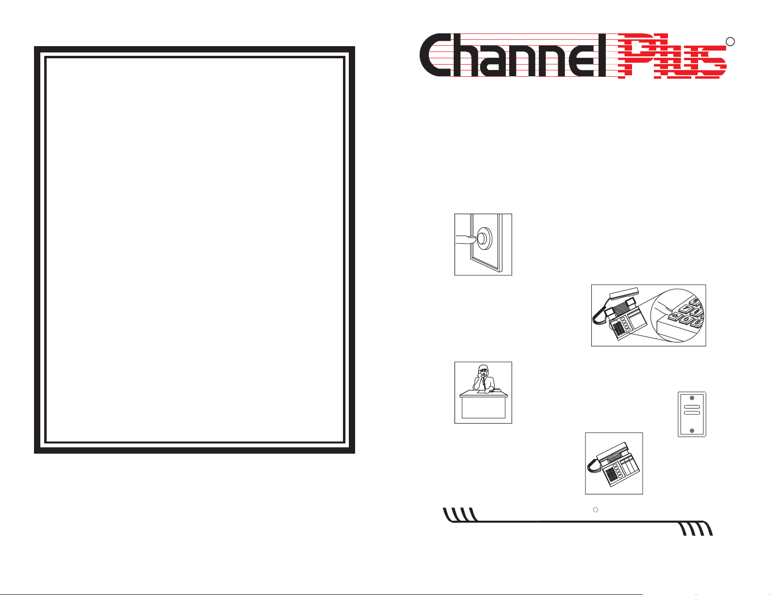
1. When the doorbell rings...
2. Go to the nearest phone...
Pick up the receiver,
and press the " " key.
*
3. Talk to the person at the entrance.
While talking, press ‘9’ to unlock
door or gate .
(model 8401 only)
model 8410
Speaker/Microphone
600-088 rev A 1997 Multiplex Technology, Inc., Brea, CA 92821
4. Hang up the phone to
turn off the speaker.
multiplex
technology, inc.
3001 Enterprise Street, Brea, CA 92821-6213, U.S.A.
714-996-4100 * 800-999-5225
R
* FAX 714-996-4900
Page 2
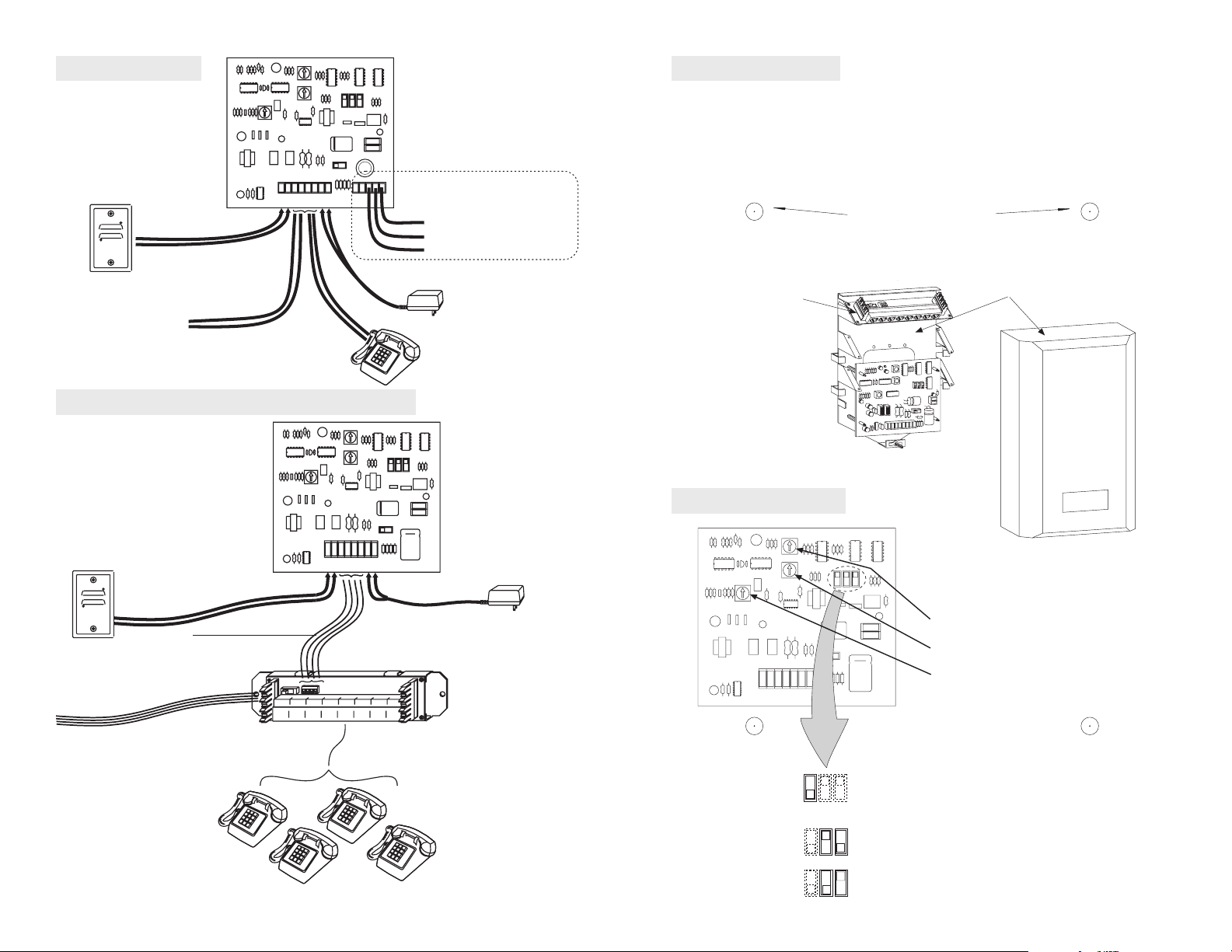
Wiring DoorTel
speaker/microphone
model 8410
Mounting DoorTel
The model 8400/8410 DoorTel may be mounted inside ChannelPlus
network enclosures by using the enclosed nylon standoffs. Optionally,
the DoorTel may be mounted on any flat surface by drilling 0.156" holes
in a 3.0" x 4.6" pattern. The hole pattern is provided below.
R R1T T1
TELCO
TELCO
12V12V
SPKR
OUT
DC
IN
Door Strike relay
(model 8401 only)
C
Consult door strike
N/C
manual for proper
N/O
wiring
Template for hole pattern
wires from
telephone company
Wiring DoorTel and the model 8051 hub
speaker/microphone
model 8410
Connect with 4 wires
Telco In R to Telco In R
Telco In T to Telco In T
1- 4 pairs
R R1T T1
12V12V
TELCO
TELCO
SPKR
OUT
IN
DC
Telco Out R to Telco Out R
Telco Out T to Telco Out T
ChannelPlus
power supply
model 350-071
power supply
model 350-071
model 8051
model 8051
Adjusting DoorTel
R R1T T1
V
12V12
TELCO
TELCO
SPKR
OUT
DC
IN
model 2600
1) Talk and listen to someone
at the front door.
2) Adjust this control for
desired audio level.
3) Adjust this control for
desired speaker level.
4) Adjust this control clockwise if
voice from the front door
chops in and out.
1-8 telephones
Use RJ 45 connectors for 4 pair
Use RJ 25 connectors for 3 pair
2
Set-up Switches
Number of tones to activate.
1
i.e. or
*
**
turns on
*
# turns off
# turns on
turns off
*
 Loading...