

Page 1
Channel
PERFORMANCE MULTI-ROOM VIDEO
Model 6110
On-Screen ID
Owner's Manual
R
ON SCREEN ID
R
LINE
VIDEO
IN
R
VIDEO
OUT
SERIAL PORT
15VDC
250mA
PHONE
multiplex
technology, inc.
3001 Enterprise Street, Brea, CA 92821-6213, U.S.A.
714-996-4100 * 800-999-5225 * FAX 714-996-4900 * www.channelplus.com
Page 2

Model 6110 - On Screen ID
Caller ID Operation
The 6110 On-Screen ID product provides a convenient way of displaying text
on top of a video source. The 6110 has an input for a phone line to display
Caller ID messages on screen and a serial interface to display messages
from a PC on screen.
The 6110 can display both name and number Caller ID messages and can
store up to 45 messages. Messages are displayed on screen when the calls
are received and are stored so that they can be reviewed later. Messages
can be deleted as a group or individually. Messages that are not deleted are
retained even if the power to the unit is lost.
The 6110 can be connected to a PC via an RS-232 serial port. The PC can
send commands and text to the 6110 to be displayed on screen. The 6110
can display text in three different sizes. It also has four text and background
shades. The 6110 also sends received Caller ID messages to the PC.
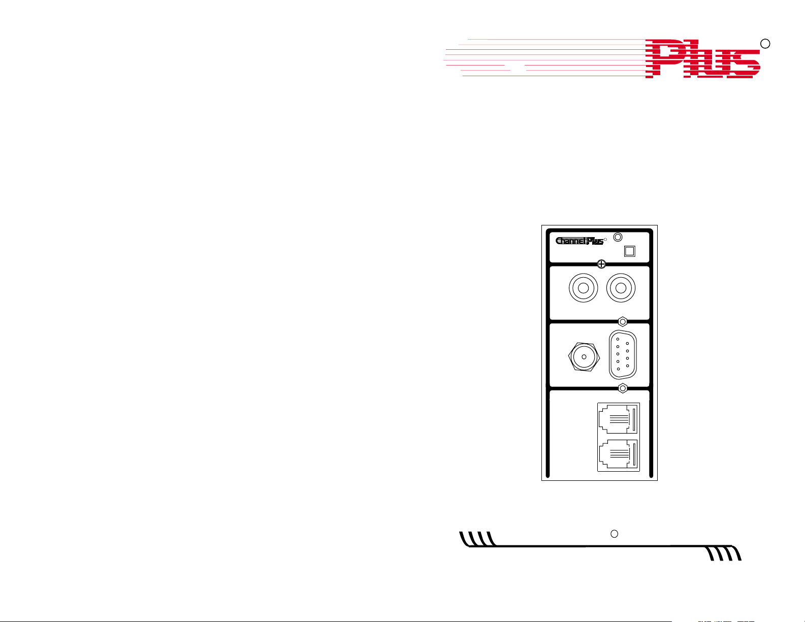
6110 Front Panel Interface
1. Power On Light.
1
2. Pressing this switch will sequence through
2
4
3
5
6
7
8
received calls. It is also used to delete
messages and select the Caller ID
message location.
3. Video Input - connect to a video source
such as VCR, DSS, etc.
4. Video Output - connect to a TV to view.
5. Serial Port (RS232) - this can be directly
connected to a PC serial port. Also has a
connection for a remote switch.
6. Power Input. Unit accepts 15VDC only.
7. Phone Line In - connect to the phone wall
jack using a standard modular cable.
8. Phone Line Out - plug a phone into the unit
here. This is optional and provided for
convenience only.
Video connections are baseband video only.
Do not use channel 3 or 4 modulated
outputs.
ON SCREEN ID
VIDEO
OUT
SERIAL PORT
15VDC
250mA
LINE
PHONE
R
VIDEO
IN
When a call is received, the number and name
will be displayed on screen. The message will
stay on screen for about 8 seconds. It is
placed in the 6110 memory for later review.
For blocked calls, the unit will display
UNKNOWN NAME or UNKNOWN NUMBER
as appropriate.
To review received calls:
Press and release button to
display each call. If display
shows END OF LOG, then there
are no more calls to display.
Continuing to press button will
cycle through the list again.
To delete individual calls:
To delete a message on the
screen, press and the
hold
button until the unit displays
MESSAGE DELETED, then
release the button.
To delete all calls in memory:
Instead of releasing the
button as above, continue to
hold the button after the unit
displays MESSAGE
DELETED until the unit
displays ALL MESSAGES
DELETED.
555-5234 Joe Anderson
DATE: 02/19 TIME: 03:42
PHONE: 555-5234
NAME: Joe Anderson
DATE: 02/19 TIME: 03:42
PHONE: 555-5234
NAME: Joe Anderson
Message Deleted
DATE: 02/19 TIME: 03:42
PHONE: 555-5234
NAME: Joe Anderson
Message Deleted
All Messages Deleted
2
3
Page 3

Changing Caller ID Display Location
The 6110 can display Caller ID messages in one of six different locations
or it can suppress them entirely. When message display is disabled, the
6110 will not display Caller ID messages when received but will still store
them in memory for later review.
To change the location of Caller ID messages:
End of Log
Sequence through received
messages until the END OF
LOG message is displayed.
Linking the 6110 to a PC
The 6110 can be linked to a PC using a standard DB-9 male to female
serial extension cable. By doing this, the PC can control the 6110 display
memory and receive Caller ID messages from the 6110. The data format
supported is 4800 baud, 8 bit, no parity, one stop bit.
The PC can send ASCII text to the 6110 via the serial port. The 6110 is
controlled via a simple command structure. ASCII codes from 32 to 253
are displayed on the screen while codes from 0 to 31 are for display
control. The 6110 will automatically go to the next text line when the
previous line is full. The following table is a list of 6110 control codes and
their function. Codes below 32 not listed are ignored.
CNTL ASCII FUNCTION
While the display still shows
END OF LOG, press and
hold
the button until the screen
location message is displayed
then release the button. If the
screen location is acceptable,
then stop. If a different
location is desired, press and
the button again until the
hold
message moves to a new
location then release.
Disabling Caller ID Display
To disable Caller ID display:
Continue to sequence
through available screen
locations as above until the
CALLER ID DISABLED
message appears.
- Caller ID location -
- Caller ID location -
- Caller ID disabled -
U 21 This control code cycles to the next text size. When sent, the entire
line displayed will be updated to the new size. The three text sizes
are 30, 20 and 10 characters per line. Can be sent anytime while
sending characters as long as it is before the next carriage return
(ASCII 13). A display reset command will set this to 30 CPL.
S 19 This control character turns on or off blinking. The blinking attribute
can be set on a character by character basis. All subsequent
characters after the command will be affected. A display reset
command will set character blinking to off.
Q 17 This control character will cycle to the next character shade. The four
shades are white, black, gray and transparent. Character shading
can be controlled on a per character basis. All subsequent characters
after the command will be affected. A display reset command will set
shading to white.
P 16 This control character will cycle to the next background shade. The
four shades are white, black, gray and transparent. This command
will affect the background shade of all characters up to and including
the last space. Can be sent anytime while sending characters as long
as it is before the next space (ASCII 32). A display reset command
will set background shading to black.
T 20 This control character will cycle to the next background shade mode.
The four shading modes are no shading, outline shading, block
shading and solid background. This command can be sent anytime
and will affect the entire display. A display reset command will set the
background mode to outline shading.
O 15 This control character will cycle to the next of four different line
spacings.
R 18 This control character will clear the display without affecting any of the
character or background attributes.
X 24 Display Reset. This control character clears the screen and resets all
of the character and background attributes to their default values.
H 08 Backspace. This will only delete the last character on the same line up
to the last carriage return.
M 13 Starts new line. A line feed (ASCII 10) is not required to go to the next
line.
4
5
Page 4

Receiving Caller ID on the PC
Specifications
The 6110 sends the received Caller ID messages to the PC when
displayed. The 6110 sends the same data in ASCII format to the PC that it
displays on the screen. This will be either two or three lines of text. Each
line is terminated with a carriage return (decimal 13) and a line feed
(decimal 10). The data format is 4800 baud, 8 bit, no parity, one stop bit.
No hardware handshaking is used. Data is sent as it is received and
cannot be sent at a later time. If the display of messages on screen has
been disabled via the front panel, no Caller ID information will be sent to
the PC. Because the data is ASCII, it can be received with a simple
terminal program running on the PC.
Remote Switch Operation
The switch on the front panel of the 6110 can be operated remotely by wiring
a switch to two pins on the serial port. Since it uses an unused pin on the
DB-9 connector, this can be done even while still using the serial port
feature. Connect a single pole momentary switch between pins 5 and 9 on
the serial connector. This switch now performs the same function as the
switch on the front panel.
Common Questions about the 6110
Video
Serial
Telephone
Temperature
Power Supply
Dimensions (HxWxD)
Input 1Vp-p @ 75
Output 1Vp-p @ 75
Character modes: 6 lines X 30 characters
Format: NTSC
Format: NTSC
4 lines X 20 characters
3 lines X 15 characters
RS-232
Data: 4800-8-N-1
Connector: DB-9
Handshaking: none
Pinout: 2 Transmit data
REN = 0.0B
Operating: 0 C to 50 C (32 F to 122 F)
Storage: -30 C to 50 C (-22 F to 122 F)
Model 350-076 (included)
Input: 120VAC, 60Hz
Output: 15VDC, 300mA
3.8" x 1.75" x 3.25" (9.7cm x 4.4cm x 8.3cm)
W
W
3 Receive data
5 Signal ground
9 Remote switch
ººº º
ººº º
Can I see the 6110 output on a TV without a video source?
No. The 6110 overlays text onto a video signal. The signal must be present
to view the output. However, the 6110 does not need a video signal to be
present to receive and store Caller ID messages or transmit them to the
serial port.
Can the 6110 overlay graphics onto video?
No. The 6110 overlays text only onto video. It is meant to display text
messages only.
If I never delete the messages, will the 6110 still work when the memory
becomes full?
Yes, the 6110 will automatically delete older messages to make room for new
ones when the memory is full.
Do you have software to use with the 6110?
Yes. It is free and can be downloaded from our WEB site at
http://www.channelplus.com
6
Set-up Diagram
Video Out
Television
ONSCREEN ID
VIDEO
OUT
SERIALPORT
15VDC
250mA
LINE
PHONE
R
Video In
VIDEO
IN
RS-232
Satellite Receiver or VCR
7
Personal Computer
Page 5

600-109 Rev. B
Multiplex Technology, Inc., Brea, CA 92821
This equipment complies with Part 68 of the FCC Rules. On the side of this equipment is a label that contains, among other
information, the FCC Registration Number and Ringer Equivalence Number (REN) for this equipment. You must, upon request,
provide this information to your telephone company.
This equipment uses two RJ14 connectors, one to interface to the line and one to interface to a phone.
This equipment is designed to be connected to the telephone network or premises wiring using a compatible modular jack
which is part 68 compliant.
The REN is useful to determine the quantity of devices you may connect to your telephone line and still have all those devices
ring when your telephone number is called. In most, but not all areas, the sum of the REN's of all devices connected to one
line should not exceed five (5.0). To be certain of the number of devices you may connect to your line, as determined be the
REN, you should contact your local telephone company to determine the maximum REN for your calling area.
If your telephone equipment causes harm to the telephone network, the Telephone Company may discontinue your service
temporarily. If possible, they will notify you in advance. But if advance notice is not practical, you will be notified as soon as
possible. You will be informed of your right to file a complaint with the FCC.
Your telephone company may make changes in its facilities, equipment, operations or procedures that could affect the proper
functioning of your equipment. If they do, you will be notified in advance to give you an opportunity to maintain uninterrupted
telephone service.
If you experience trouble with this telephone equipment, please contact Multiplex Technology Inc. at 800-999-5225 for
information on obtaining repairs. The telephone company may ask that you disconnect this equipment from the network until
the problem has been corrected or until you are sure that the equipment is not malfunctioning.
No user serviceable parts contained in this equipment.
This equipment may not be used on coin service provided by the telephone company. Connection to party lines is subject to
state tariffs.
Warranty
Multiplex Technology, Inc., warrants this product to be free from defects
in materials and workmanship for a period of one year from the date of
purchase or MTI will repair or, at its option, replace the defective
product. To obtain warranty service, call MTI for a Return Material
Authorization (RMA) number and return the product pre-paid
accompanied by a copy of the purchase receipt, to Multiplex
Technology, Inc., 3001 Enterprise St., Brea, CA 92821, Attn: Customer
Service. Please put the RMA number on the outside of the carton.
Any implied warranty arising from the sale of the product including
implied warranties of merchantability and fitness for purpose are limited
to the warranty stated above. MTI shall not be responsible for any loss,
damages or expenses, whether direct, consequential, or incidental
arising from the use or inability to use this product. Some states do not
allow limitations on how long an implied warranty lasts or the exclusion
or limitation or incidental or consequential damages, so the above
limitations may not apply to you. This warranty gives you specific legal
rights, and you may have other rights which vary from state to state.
multiplex
technology, inc.
600-109 Rev. B
®
3001 Enterprise Street, Brea, CA 92821-6213, U.S.A.
714-996-4100 * 800-999-5225
Multiplex Technology, Inc., Brea, CA 92821
* FAX 714-996-4900
 Loading...