

Page 1
Page 2
The serial number can be found on the back of the
amp, near the power switch. Please note it in the
space provided below for future reference.
SERIAL NUMBER
WARNING: TO REDUCE THE RISK
OF FIRE OR ELECTRIC SHOCK, DO
NOT EXPOSE THIS APPLIANCE TO
RAIN OR MOISTURE.
CAUTION: This equipment has been tested
and found to comply with the limits for a Class B
digital device pursuant to Part 15 of FCC Rules.
Operation is subject to the following two
conditions: (1) This device may not cause harmful
interference, and (2) this device must accept any
interference received, including interference that
may cause undesired operation.
AxSys 212 UserÕs Manual, Version 1.2
© 1996, Fast Forward Designs, Inc.
Line 6, AxSys, and Tube Tone are trademarks of Fast Forward Designs, Inc. All other product tradmarks are the
property of their respective owners. Any reference to sound models of specific products does not imply
cooperation nor endorsement from those manufacturers.
CAUTION: TO REDUCE THE RISK OF ELECTRIC
SHOCK, DO NOT REMOVE SCREWS. NO USERSERVICEABLE PARTS INSIDE. REFER SERVICING TO
QUALIFIED SERVICE PERSONNEL.
The lightning symbol within a triangle
means Òelectrical caution!Ó They include
information about operating voltage and
potential risks of electrical shock.
The exclamation point within an triangle
means Òcaution!Ó Please read the
information next to all caution signs.
Important Safety Instructions
Before using this AxSys 212, be sure to carefully read the applicable items
of these operating instructions and the safety suggestions.
1 Obey all warnings on the amp and in the User Manual.
2 Do not place near heat sources, such as radiators, heat registers, or
appliances which produce heat.
3 Guard against objects or liquids entering the enclosure.
4 Connect only to AC power outlets rated 100-120V or 200-240V 47-63Hz
(depending on the voltage range of the unit; refer to back panel).
Current ratings should be a minimum of 5A for the 120V range and
2.5A for the 240V range.
5 Do not step on power cords. Do not place items on top of power
cords so that they are pinched or leaned on. Pay particular attention
to the cord at the plug end and the point where it connects to the amp.
6 Unplug the amp when not in use for extended periods of time.
7 Do not perform service operations beyond those described in the User
Manual. In the following circumstances, repairs should be performed
only by qualified service personnel:
¥ liquid is spilled into the unit
¥ an object falls into the unit
¥ the unit does not operate normally or changes in performance in a
significant way
¥ the fuse is blown
¥ the unit is dropped or the enclosure is damaged
8 Prolonged listening at high volume levels may cause irreparable
hearing loss and/or damage. Always practice Òsafe listeningÓ.
2 AxSys 212 User Manual
Page 3

Contents
CONTENTS
Chapter 1: Quick Start ............................................................................ 5
Chapter 2: The Guided Tour ................................................................. 6
Overview ........................................................................................................... 6
Unpacking ......................................................................................................... 6
Power Hookup.................................................................................................. 6
Connections....................................................................................................... 7
Powering Up ..................................................................................................... 8
Adjusting Volume Levels................................................................................ 9
Tuning Up ......................................................................................................... 10
Auditioning Sounds......................................................................................... 11
Main Controls ................................................................................................... 12
The AxSys Signal Path..................................................................................... 13
The Effects Tables............................................................................................. 13
Quick Editing Primer....................................................................................... 14
Viewing Each ParameterÕs Setting................................................................. 15
Comparing an Edited Sound to the Original ............................................... 16
Storing Edited Sounds ..................................................................................... 16
Foot Pedals ........................................................................................................ 17
Using the Aux Input ........................................................................................ 18
Chapter 3: Description of Features....................................................... 19
What is TubeToneª?....................................................................................... 19
What is a Sound? .............................................................................................. 19
Memory ............................................................................................................. 19
Sound Buffer ..................................................................................................... 20
Parameters......................................................................................................... 21
Input Controls................................................................................................... 21
Input Effects ...................................................................................................... 22
Preamp Controls............................................................................................... 26
Rack Effects ....................................................................................................... 28
FX On/Off ......................................................................................................... 35
Aux Controls..................................................................................................... 36
Global Controls................................................................................................. 37
Appendices ............................................................................................... 39
Appendix I: Troubleshooting ......................................................................... 39
Appendix II: Maintenance & Service ............................................................ 39
Appendix III: Tube Replacement ................................................................... 41
Appendix IV: About Audio Cables ............................................................... 41
Appendix V: Using External Speaker Cabinets ........................................... 41
Appendix VI: Specifications ........................................................................... 42
Appendix VII: MIDI Implementation Chart ................................................ 43
Appendix VIII: MIDI Program Change Chart ............................................. 44
Index .......................................................................................................... 45
AxSys 212 User Manual 3
Page 4

Contents
Introduction
WELCOME TO THE AXSYS 212 DIGITAL GUITAR SYSTEM!
The AxSys 212 is the first of its kind Ð a new generation of guitar amp. In
the past, searching for the right ÒtoneÓ meant trying out dozens of amps Ð
each having its own unique, signature sound. If you wanted more than
one sound, you needed more than one amp to cover all the bases.
Now, many of the classic guitar amp sounds are yours at the touch of a
button. Thanks to new technologies and Òphysical modelingÓ, the AxSys
212 can imitate almost any guitar amp on the market today (and plenty of
vintage amps that are no longer made). AxSysÕ unique TubeToneª
design emulates the internal circuitry of various guitar amps, giving you
the tone youÕre looking for Ð without having to buy (or cart around) all
those other amps, or deal with ÒmoodyÓ tubes. Physical modeling also is
used to emulate sounds like spring reverb, and even an acoustic guitar.
And what about all those rack-mount effects and pedal boxes on the floor?
AxSys provides a full complement of state-of-the-art 24-bit simultaneous
stereo digital effects including: noise gate, hum canceller, compressor,
wah, distortion box, multiple EQs, chorus, flange, delay, reverb, cabinet
simulation, and a lot more Ð itÕs all in there! ThereÕs even a digital tuner.
The AxSys 212 is programmable, with 128 presets and 128 user sounds,
that can be selected by MIDI foot pedals, sequencers and computers. Top
it off with twin custom 12" Eminence speakers and 100 Watts of stereo
power, and you have one very powerful system in a portable package.
YouÕre probably anxious to get started and make some music, right? First,
letÕs tell you about how this manual is organized and how best to use it...
About this Manual
This manual will help you get the most out of your AxSys 212 Digital
Guitar System. We suggest you read through the manual once completely.
Then use the Table of Contents and Index for specific topics or features.
☞
If, like the rest of us, you have no patience and require instant gratification,
jump right over to chapter 1 right now.
The manual has been divided into the following sections:
¥ Chapter 1,
¥ Chapter 2,
sound selection and tone shaping.
¥ Chapter 3,
and how to achieve the sound youÕre searching for.
Quick Start, will get you up and running quickly.
The Guided Tour, will walk you through the basics of
Description of Features, explains the features of the AxSys,
¥ The
4 AxSys 212 User Manual
Appendices cover specifications, troubleshooting and maintenance
tips, MIDI implementation, and use of external speakers.
Page 5
Quick Start: Chapter 1
CHAPTER 1: QUICK START
To quickly get going with the AxSys 212, follow these steps:
1 Turn the
2 Plug the power cord into the rear
3 Connect your guitar to the AxSysÕ
4 Turn on the AxSys by pressing the
GUITAR, AUX and MASTER knobs all the way down to zero.
POWER connector and AC power.
GUITAR INPUT jack.
POWER button on the rear panel.
5 Adjust the volume levels using the following procedure:
a) Select your guitarÕs loudest pickup and set its volume to max.
b) Play your guitar as loud as possible.
c) Slowly turn the
d) Turn the knob back slightly so the
e) Turn the
MASTER knob up to a comfortable listening level.
GUITAR knob clockwise until the CLIP LED lights.
CLIP LED flashes occasionally.
6 Audition the AxSysÕ Preset Sounds using the following procedure:
a) Press the
USER/PRESET
button to select the Preset Bank (P).
If the left-most character in the display reads U or E, press it again.
b) Use
c) Press
▲
SOUND BANK
SOUND
A
/
,
SOUND BANK
▼
SOUND
B
to select a Bank from 01 to 32.
SOUND
,
C
, or
SOUND
D
to select a Sound
from the current Sound Bank.
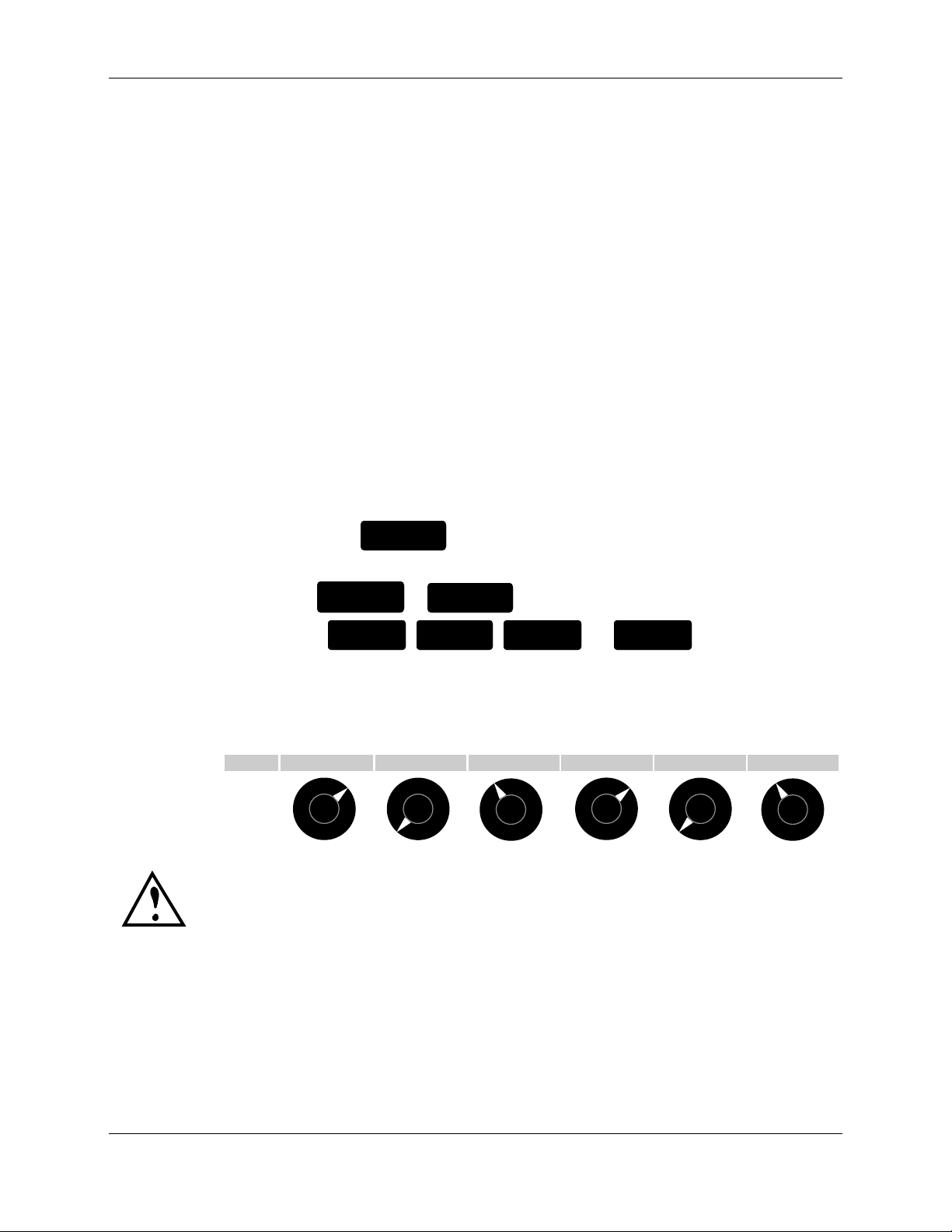
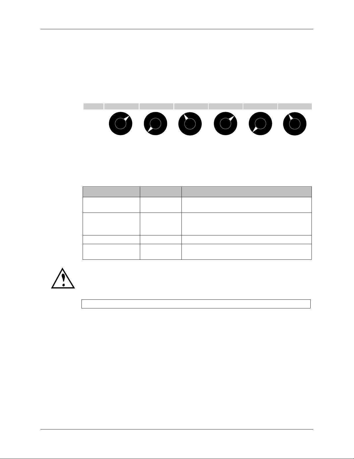
7 To tweak a Sound, turn one of the six Control Knobs located in the
middle of the front panel. These Controls are labeled as follows:
DRIVE BASS MIDMAIN TREBLE GAIN DELAY/REVERB
•
•
•
•
•
•
•
•
•
•
•
•
•
•
•
•
•
•
•
•
•
•
•
•
•
•
•
•
•
•
•
•
•
•
•
•
•
•
•
•
•
•
•
•
•
•
•
•
•
•
•
•
•
•
•
•
•
•
•
•
•
•
•
•
•
IMPORTANT!!! The Control Knobs may not appear to function properly at first.
This is because you must ÒcaptureÓ a ControlÕs setting before it will change.
When you turn a Control Knob, its current setting appears in the display.
However, this setting will not change until the Control Knob is turned to
match the stored setting. Once the ControlÕs setting is captured, the
Control Knob will work as you would expect to adjust the ControlÕs value.
8 For now, donÕt worry about the groups of parameters shown on the
front panel. DonÕt even look at Õem! WeÕll discuss these further in
chapter 3. Just start playing!
AxSys 212 User Manual 5
•
Page 6
Chapter 2: The Guided Tour
CHAPTER 2: THE GUIDED TOUR
Overview
This chapter is meant to provide a detailed guide in the setup and use of
the AxSys 212 Digital Guitar System.
Important Things To Know
There are two very important things you will learn about in this chapter:
¥ Setting input levels. This is something uncommon with analog guitar
amplifiers. However, achieving the best possible tone relies heavily on
input level settings. See page 9 for more information.
¥ Control Knobs. These are used to tweak your sound. Because the
AxSys 212 is programmable, itÕs common to recall a Sound which has
its Drive, Bass, Mid, etc., set differently than where the Control Knobs
are positioned. Instead of turning a knob and having it immediately
alter a setting, the Control Knob must first ÒcaptureÓ the ControlÕs
stored setting before it will change the setting. This may be surprising
at first, but there is a very good reason for it. See page 13 for more
information.
Unpacking
Along with this User Guide and your AxSys 212, you should find a
registration card, a warranty information sheet, a Preset Sounds chart, and
a power cable.
Registration Card
Please take time to fill this out and return it right now. This ensures that
you will be notified of all software and hardware upgrades and new
products as they become available.
Power Hookup
The AxSys works with the voltage of the country it is shipped to, and
comes with a line cord suitable for the destination to which the amp is
shipped.
With the AxSys off, plug the power cord into the AxSysÕ rear panel
socket and into a source of AC power. ItÕs good practice to not turn on the
AxSys until all other cables are connected.
Line 6 cannot be responsible for problems caused by using the AxSys or any
associated equipment with improper AC wiring.
POWER
6 AxSys 212 User Manual
Page 7

Connections
Plugging in Your Guitar
The Guided Tour: Chapter 2
Connect your guitar to the AxSysÕ
GUITAR INPUT jack.
Auxiliary Input
The
AUX INPUT jack is designed for a second audio source, like a
microphone, drum machine, tape player, or acoustic guitar, separate from
the main Guitar input.
Footpedals
The rear panel of the AxSys provides two separate foot pedal jacks labeled
PEDAL 1 (VOLUME) and PEDAL 2 (WAH). These accept a Roland model EV-
5 (or equivalent type) volume control pedal.
You can also connect a standard volume pedalÕs output to either the
PEDAL 1 (VOLUME) or PEDAL 2 (WAH) jacks. However, the scaling may not
be accurate; i.e. youÕll notice that the effect happens too quickly. To
compensate for this, try soldering in a 10k ohm resistor between the tip
and the sleeve at either end of the 1/4" cable you are using to connect the
pedal. This should offset the difference in the pedalÕs pot resistance and
even out its control.
If you have only one pedal, connect it to the
PEDAL 1 (VOLUME) jack. It can
then be used to control volume or Wah (see page 17).
Pedal Board
The optional AxSys Pedal Board connects to the PEDAL (REMOTE) multipin
connector (the one that kinda looks like a telephone jack... but itÕs not),
and provides foot control functions including: Volume and Wah pedals,
Effects On/Off switches and Sound select buttons and displays.
Internal Speakers
The two built-in custom Eminence speakers each have a cable attached
which are already connected to the
LEFT SPEAKER and RIGHT SPEAKER
rear panel jacks. For information about using external speakers, refer to
Appendix V in the back of this manual.
Headphones
Connect headphones to the HEADPHONE/STEREO LINE OUT jack on the
rear panel. Whenever headphones are connected to the AxSys, the internal
speakers will continue to work, so you can unplug them if you want. This
will not harm the amplifier.
AxSys 212 User Manual 7
Page 8
Chapter 2: The Guided Tour
Stereo Line Out
If you want to connect the AxSysÕ output to another amp, or into a mixing
board, connect a stereo TRS (tip-ring-sleeve) cable to the HEADPHONE /
STEREO LINE OUT jack on the rear panel. This jack provides a stereo line
level output. If you want to use the
speakers playing as well, disconnect the speakers.
When you connect a cable to the HEADPHONE/STEREO LINE OUT jack , the
AxSys automatically enables its Speaker Emulator which simulates the frequency
response of the speakers and the cabinet. However, if you leave the AxSysÕ internal
speakers connected while using the
speakers will sound noticeably darker.
STEREO LINE OUT without the internal
HEADPHONE/ STEREO LINE OUT jack , the
TIP
If you want to turn off the automatic Speaker Emulator when you
use the
Select button labeled
the amp (we chose that button because it corresponds to the
Cabinet parameters, which makes it easier to remember). The
display will temporarily flash HPn and OFF to indicate that the
Headphone Speaker Emulator has been temporarily disabled. To
enable it again, turn the amp on again without holding any buttons.
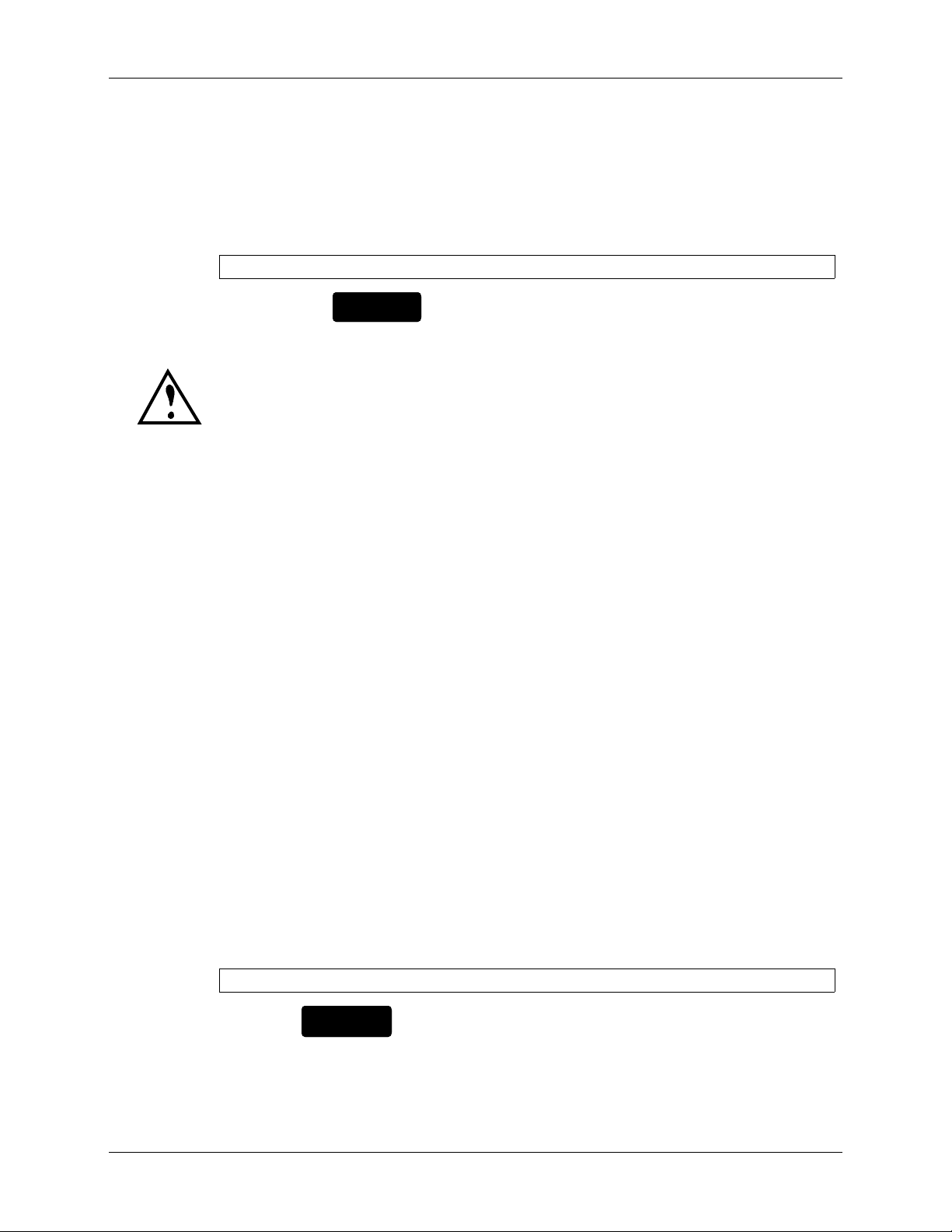
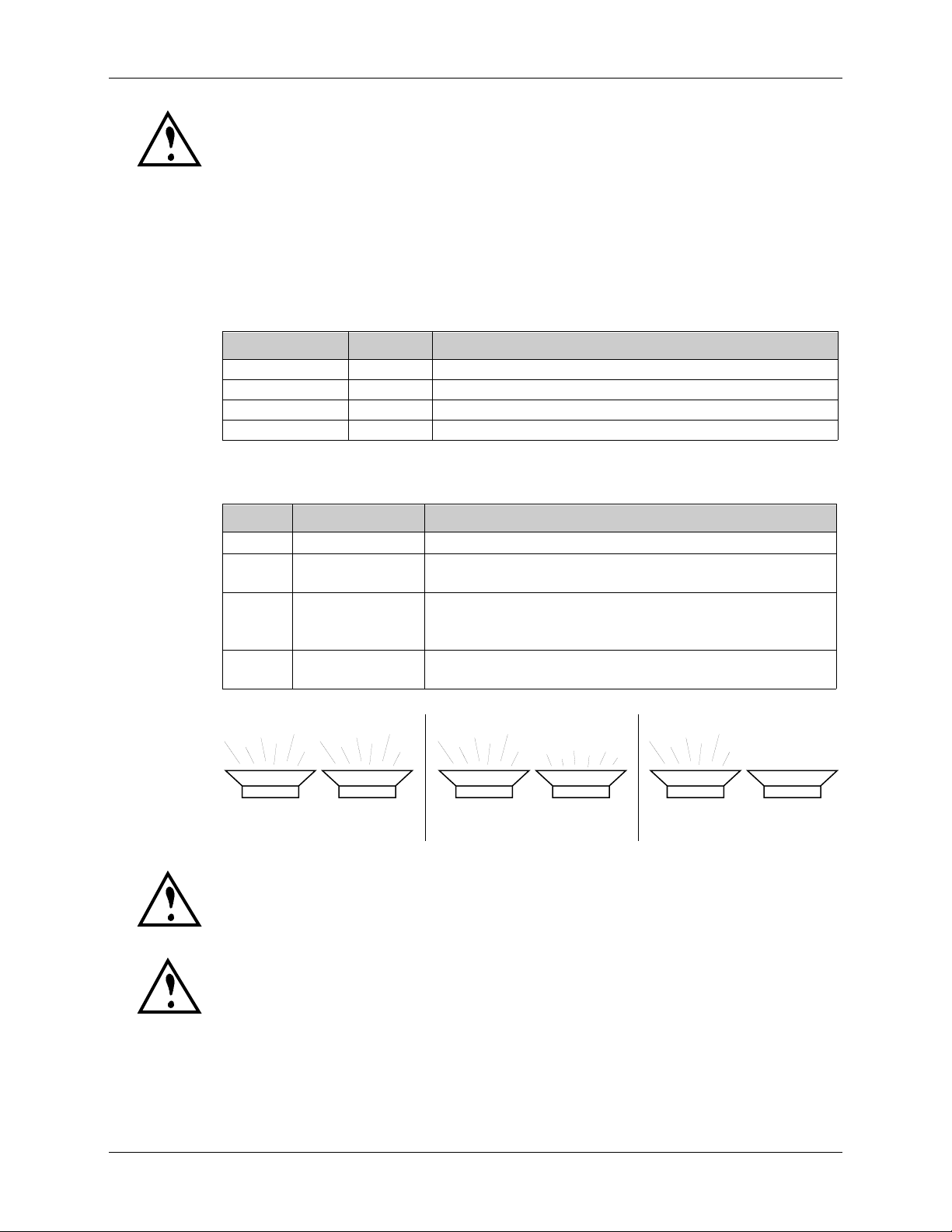
Powering Up
Once all connections are made, turn down the MASTER volume and power
up the AxSys 212 with the
over the power cord.
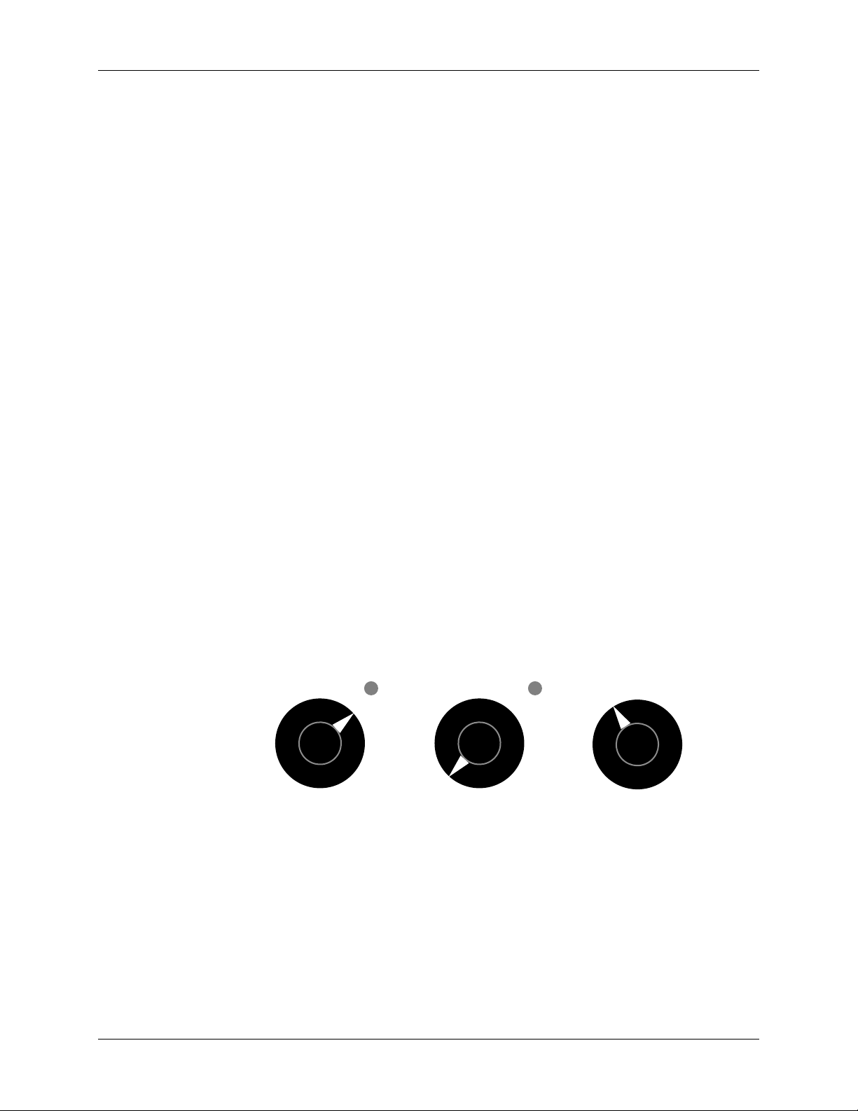
The display should look something like this:
This means that Preset Sound Bank 01 is selected.
After power-up, the AxSys will recall the Sound that was selected before it
was last turned off. The display will indicate the current:
HEADPHONE/STEREO LINE OUT jack, hold down the Row
GRAPHIC EQ and TREMOLO/CAB while turning on
POWER switch located on the AxSys rear panel
P01
¥ Mode: Preset, User or Edited
¥ Sound Bank: 01 through 32
...and one of the four
¥ Sound: A, B, C or D
8 AxSys 212 User Manual
SOUND LEDs (▼) will be lit to indicate the current:
Page 9
Example: If, when power was last turned off, the selected mode was Preset
and the selected Sound was 28B, the LED display would now read P28,
and the LED pointer above the SOUND B button would be lit.
If the selected Sound was edited, the display will indicate this by showing
an E to the left of the Sound Bank number, instead of a P or U, like this:
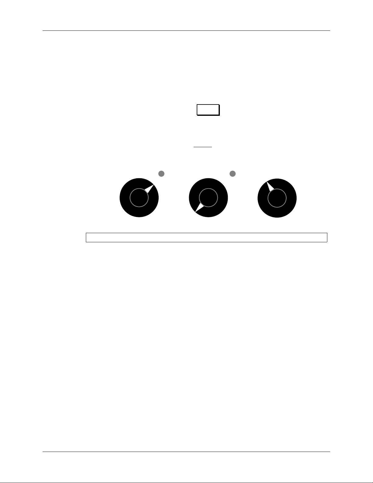
Adjusting Volume Levels
In order to get the best tone, it is really important that you set the input
level as loud as you can before clipping.
The Guided Tour: Chapter 2
E28
GUITAR AUX MASTER
•
46
•
2
•
0
CLIP CLIP
•
46
•
8
•
10
•
2
•
0
10
•
46
•
8
•
•
2
•
0
•
8
•
10
To set the volume levels:
1 Turn the GUITAR, AUX and MASTER knobs on the left side of the front
panel down to zero.
2 On your electric guitar, select the loudest pickup.
If your guitar has a humbucking pickup, use it. Otherwise, try the pickup
closest to the neck.
3 Turn your guitarÕs volume and tone controls to max.
4 Play your guitar as loud as possible.
5 Slowly turn the
Continue playing loudly while adjusting this knob until the
GUITAR input knob clockwise.
CLIP LED lights
up.
6 Turn the
GUITAR input knob counterclockwise slightly.
This will set the input level to a point where clipping will only occur
occasionally when playing your guitar hard.
7 Repeat steps 2 and 3 for the
AUX input if youÕre going to use it.
Example: If using a microphone, sing loudly into the microphone and adjust
AUX knob until the CLIP LED flashes occasionally.
the
8 Adjust the
AxSys 212 User Manual 9
MASTER knob to a comfortable listening level.
Page 10
Chapter 2: The Guided Tour
Tuning Up
Before you start checking out the incredible sounds of the AxSys 212, you
may want to tune up your guitar with the on-board tuner.
To use the Digital Tuner:
1 Press the
The six LEDs located above the six Control Knobs in the middle section of the
front panel will switch to tuner mode, first displaying the tuning reference
(usually 440), and then the displaying ---.
2 Play a single string on your guitar and let it sustain.
The display will indicate the note you are playing
above the six Control Knobs will indicate whether you are flat or sharp.
Sharp: ❍❍❍❍✹❍
TUNER
TAP TEMPO
button; its LED will light.
1
and the LEDs located
❍❍❍❍❍✹
❍❍❍✹❍❍
TIP
In tune:
❍❍✹✹❍❍
❍❍✹❍❍❍
Flat: ❍✹❍❍❍❍
✹❍❍❍❍❍
3 Optional: To monitor the guitar while tuning, turn the GAIN Control
Knob to adjust the guitarÕs signal level from 0 to 99.
While in Tune mode, all effects will be bypassed and youÕll only hear your
guitarÕs signal passed through unaltered. Note: This does not affect the tuner.
4 Also optional: Turn the
The tuning reference range is 435 to 445Hz. When the
MID Control Knob to adjust the reference.
MID Control Knob is
set to the 12 oÕclock position, the tuning reference will be A=440Hz.
TUNER
The
TAP TEMPO
button will not select Tuner mode if the Delay parameters are
being edited. When the Delay Edit Row is selected, this button provides a ÒTap
TempoÓ function, so that the
MAIN DELAY TIME parameter can be set by tapping
it at the desired tempo. For more information, see page 31 in chapter 3.
When you use the Tuner, the Aux Input will still work. So if you use the
Aux Input with a microphone, you can talk to your audience while
youÕre tuning up (ÒdonÕt forget to tip your server...Ó).
1
Accidentals (sharps and flats) are always displayed as flats. Example: If you play the
note D#, it will be displayed as Eb (Eb).
10 AxSys 212 User Manual
Page 11
Auditioning Sounds
A Sound is a stored setup that instantly recalls a defined tone. The AxSys
212 includes 64 Sound Banks, divided into two sets of 32 (Preset and
User). Each Bank has four Sounds, which adds up to 256 killer tones to
choose from!!
The first 32 Sound Banks are called ÒPresetÓ. These are programmed at the
factory and canÕt be erased. The second set of 32 Sound Banks are called
ÒUserÓ. These are completely modifiable, movable and erasable. Of
course, you can modify a Preset Sound and store it in the User Bank.
To Audition Sounds:
The Guided Tour: Chapter 2
1 Press the
USER/PRESET
button to select either the Preset or User Bank.
Each time the button is pressed, the left-most character in the display toggles
between U (User) and P (Preset).
2 Use the
▲
SOUND BANK
SOUND BANK
/
▼
buttons to select a Sound Bank.
The right-side of the display will display the selected Bank number between
01 and 32. Holding down either button will cause the display to scroll
through the Banks quickly. None of the LED pointers
▼ will be lit to indicate
that a new Sound has not yet been recalled.
3 Press either
SOUND
A
SOUND
,
B
SOUND
,
C
, or
SOUND
D
to select a
Sound from the current Sound Bank.
An LED pointer ▼ will light up above the Sound button that was pressed.
Whenever you change Sound Banks, the sound youÕre using wonÕt change until
you press one of the Sound A-D buttons.
Because each Bank holds four Sounds (A, B, C and D), itÕs easy to group
Sounds that go together. Example: Sounds that are used in the same song.
Sound A could be used for a songÕs Intro section, Sound B for the Verse (a
little softer, fewer highs and less distortion and reverb), Sound C for the
Chorus and Sound D for the Solo (much louder, maximum distortion and
delay).
Of course, you can change and then store any User Sound. If you want to
keep both the original and edited versions of the Sound, you might want
to store the edited version to a different User location. This will replace the
previous User Sound in that location, so you may want to first designate
which User Sounds are ÒexpendableÓ before choosing a location. The
Compare mode can be used for this as well (see page 16). If you like a
Preset Sound but wish to store it in a modified form, you can store it in a
User Sound.
AxSys 212 User Manual 11
Page 12
Chapter 2: The Guided Tour
Main Controls
The six Control Knobs (in the middle of the front panel) allow you to
tweak any Sound by giving you instant access to the most needed
controls. These knobs are used to adjust all parameters depending on the
Edit Row you select. The Edit Row is indicated by an LED pointer
MAIN Row is automatically selected whenever a new Sound is called up.
•
•
•
Since the settings for these Controls can change drastically from one
Sound to another, the positions of the Control knobs wonÕt always reflect
the true setting. Instead, the LEDs located next to each Control knob will
get brighter to show the new setting of each knob.
Main Controls Range Definition
. The
▲
DRIVE BASS MIDMAIN TREBLE GAIN DELAY/REVERB
•
•
•
•
•
•
•
•
•
•
•
•
•
•
•
•
•
•
•
•
•
•
•
•
•
•
•
•
•
•
•
•
•
•
•
•
•
•
•
•
•
•
•
•
•
•
•
•
•
•
•
•
•
•
•
•
•
•
•
•
•
•
•
DRIVE 0 to 99 Controls the volume of the signal going into the
Preamp; use high levels to create distortion.
BASS
MID
TREBLE
-50 to 50
(-12.5dB to
+12.5dB)
Control the level of low, middle and high
frequencies, respectively, of the signal before it is
routed to the digital effects (delay, reverb, etc.).
GAIN 0 to 99 This is the Guitar channelÕs output volume.
DELAY/REVERB 0 to 99 This is a master effects level control for both the
Stereo Delay and Stereo Reverb effects.
The DRIVE control is disabled when the Acoustic Sim Preamp type is selected (you
donÕt really want to distort your acoustic anyway, do you?). See page 28 for more
information about the Acoustic Simulator Preamp type.
To Edit a Main Control:
1 Press the MAIN Row Select button.
MAIN Row LED indicator should be lit.
The
2 Turn the knob you want to adjust either direction until it ÒcapturesÓ
the current setting.
Notice the LED located next to the knob will change in brightness to reflect
the parameterÕs setting.
When turning any Control Knob, the parameter being modified shows in
the LED display. Your new setting will remain for a few seconds after
youÕve stopped turning the Control Knob. After which, the display will
12 AxSys 212 User Manual
Page 13

The Guided Tour: Chapter 2
revert back to the currently selected Sound Bank number; notice an E will
appear (instead of a P or U) to indicate that the Sound has been ÒeditedÓ.
IMPORTANT: Since each Control knob is used for lots of parameters, turning
one will not have an instant affect until it Òpasses throughÓ the current setting of
the parameter being edited.
Example: LetÕs say the
DRIVE Control Knob is positioned all the way to the
right, and then you select a Sound which has its Drive set to 12 oÕclock
(50%). Turning the
DRIVE Control Knob counterclockwise wonÕt have an
immediate affect (its LEDÕs brightness will not change and the display will
read 50). You wouldnÕt want the Drive parameter to suddenly ÒjumpÓ to
the knobÕs position as soon as you touched it. However, if you continue to
turn the Control Knob counterclockwise so that it passes through the 12
oÕclock position, you will then be able to adjust the parameter directly.
Once a Sound has been edited,
¥ An ÒeditedÓ Sound differs from its original, ÒstoredÓ version (what a
concept!).
¥ If a new Sound is selected before storing the edited Sound, the edited
Sound will be lost (what a bummer!).
Once youÕve made adjustments that youÕre happy with, you will want to
store the Sound to save these changes and make them permanent. See
page 16 for information about storing an edited Sound.
The AxSys Signal Path
remember:
On the right side of the front Panel thereÕs an illustration of the AxSysÕ
internal signal path. This will help you learn the order the signal passes
through each of the internal digital components. The path is:
Guitar Input ➠ Noise Gate ➠ Compressor ➠ Volume Pedal* (Pre) ➠ Distortion Box ➠
Wah ➠ Preamp EQ ➠ Preamp ➠ Volume Pedal* (Post) ➠ Auto Volume ➠ Graphic EQ ➠
Bass/Middle/Treble ➠ Stereo Tremolo ➠ Stereo Delay ➠ Stereo Chorus ➠ Stereo Reverb
➠ Cabinet Simulator ➠ Speakers
* Note: The Volume Pedal may be placed either before (Pre) or after (Post)
the Preamp section.
The Effects Tables
Directly beneath the signal path diagram are a series of effect tables. These
tables indicate what various parameters mean. Example: When you know
you want to use the Stereo Delay, the
DELAY TYPE parameter to 2.
AxSys 212 User Manual 13
DELAY TYPE table tells you to set the
Page 14
Chapter 2: The Guided Tour
Quick Editing Primer
Aside from the six Main Controls (see page 12), many other parameters
are available to you that provide for greater control over your tone. If you
want more detail, check out chapter 3. For now, weÕll give you a quick
way to navigate through the Edit Rows to get to various parameters.
TIP
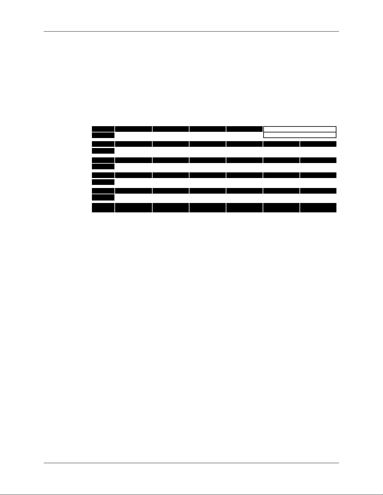
The parameters that make up a Sound are found in the
Òparameter matrixÓ
located above the six Control Knobs:
AUX/MIDI AUX INPUT MIX AUX INPUT BASS AUX INPUT TREBLE AUX INPUT REVERB MIDI CHANNEL TRANSMIT SOUNDS
NOISE GATE NOISE GATE ON/OFF NOISE GATE THRESHOLD NOISE GATE DECAY HUM CANCELLER GATE/HUM PER SOUND AUX PER SOUND
COMP/PEDALS COMPRESSION LEVEL VOLUME PEDAL ON/OFF DISTORTION BOX WAH TYPE WAH DEPTH AUTO-VOLUME ATTACK
PREAMP PREAMP TYPE PREAMP BASS PREAMP MIDDLE PREAMP TREBLE BRIGHT SWITCH PREAMP OUTPUT LEVEL
GRAPHIC EQ 80Hz 240Hz 750Hz 2200Hz 6600Hz PRESENCE
TREMOLO/CAB TREMOLO TYPE TREMOLO SPEED TREMOLO DEPTH TREMOLO SHAPE CABINET TYPE CABINET STEREO SPREAD
DELAY DELAY TYPE MAIN DELAY TYPE DELAY TIME OFFSET DELAY FEEDBACK DYNAMIC DELAY DELAY LEVEL
CHORUS CHORUS TYPE CHORUS SPEED CHORUS DEPTH CHORUS FEEDBACK CHORUS SHAPE CHORUS LEVEL
REVERB REVERB TYPE PREDELAY REVERB DECAY REVERB TONE REVERB DIFFUSION REVERB LEVEL
FX ON/OFF DISTORTION BOX ON/OFF DRIVE ON/OFF EQ ON/OFF TREM/CHORUS ON/OFF DELAY ON/OFF REVERB ON/OFF
MAIN DELAY/REVERBGAINTREBLEMIDBASSDRIVE
The parameter matrix is divided into 11 Edit Rows. The name of each Edit
Row may be found running down the left side of the parameter matrix
(these include:
EQ, TREMOLO/CAB, DELAY, CHORUS, REVERB, FX ON/OFF and MAIN).
AUX/MIDI, NOISE GATE, COMP/PEDALS, PREAMP, GRAPHIC
Think of each Edit Row as a different effect in your rack.
What a Control Knob will do when you turn it depends on the Edit Row
youÕve selected. Five Row Select buttons (located along the left side of the
parameter matrix) let you select any of the Rows. There are two Edit Rows
associated with each Row Select button.
The first time a Row Select button is pressed, the upper Edit Row
associated with that button will be selected. If the Row Select button is
pressed again, the lower Edit Row associated with that button is selected.
Each time the same Row Select button is pressed, youÕll toggle between its
two Edit Rows.
The currently selected Edit Row is indicated by an LED pointer
. Each
▲
Edit Row provides six different Controls which are usually, but not
always, associated with a common function or effect. Example: In the
GRAPHIC EQ Row, the Control knobs let you adjust the various frequency
bands of the Graphic Equalizer module.
14 AxSys 212 User Manual
Page 15

To Edit a Parameter:
1 Locate the Parameter in the chart located above the six Control Knobs.
2 Select that ParameterÕs Edit Row by pressing one of the five Row Select
buttons. If the incorrect Edit Row was selected, press the same Row
Select button a second time.
The LED pointer for that Row will light to indicate it has been selected.
3 Turn the associated Control Knob for that parameter.
The LED above the knob will change in brightness to reflect its setting.
Viewing Each Parameter’s Setting
YouÕve learned that you can view a parameterÕs setting in the display by
simply changing it (i.e. turn a Control Knob and its value instantly
appears in the display). You can also view the LEDs located next to each
Control Knob to get a rough idea of eachÕs setting for the selected Edit
Row Ð a brightly lit LED indicates a high or maximum setting, while a dim
LED indicates a low setting.
The Guided Tour: Chapter 2
Sometimes you may want to view a parameterÕs exact setting without
having to change its setting. Fortunately, you can view all six Control
KnobsÕ settings for a single Edit Row,
settings, by holding down the adjacent Row Select button.
To View each ParameterÕs Setting within an Edit Row:
1 Press and hold one of the six Row Select buttons.
While holding the button, the display will cycle through each parameter in the
selected Edit Row and will show the current setting of each in succession.
Only one of the LED indicators located next to each of the six Control Knobs
will be lit to indicate which is the currently displayed parameter.
2 While holding a Row Select button, you can turn any Control Knob to
view its related parameterÕs setting without changing it.
without having to change their
AxSys 212 User Manual 15
Page 16
Chapter 2: The Guided Tour
Comparing an Edited Sound to the Original
If a Sound has been edited (the display reads E), it may be compared to
the original version. In other words, without losing the edited version of a
Sound, you can go into Compare mode and listen to the SoundÕs original,
stored version, then exit Compare mode to listen to the edited version.
To toggle between Edited and Compare modes:
COMPARE
TIP
1 Press the
Each time the button is pressed, the left-most character in the display toggles
between E (Edited) and C (Compare).
If a Sound hasnÕt been edited, Compare mode wonÕt do anything, of course.
While in Compare mode, you can move around the parameter matrix (i.e.
press the Row Select buttons and turn the Control Knobs) to examine the
original stored settings, but you wonÕt be able to edit them.
You can use Compare mode to select other Sounds in the User Bank
in order to find a suitable location for the Sound youÕve been
editing. When you change Sounds (A-D) and/or Banks (01-32) while
in Compare mode, youÕll be able to hear the Sound stored in that
location without losing the changes youÕve made to the Sound you
were editing. Once you find a suitable location (i.e., a lame patch)
to store the edited Sound into, just press STORE SOUND twice (see
below) and the edited Sound will be stored into the displayed
location.
Storing Edited Sounds
button.
Once youÕve made changes to a Sound, you need to store the Sound into
one of the User Banks if you want to keep the changes. The User Banks
hold up to 128 Sounds (01Ð32, AÐD). When you try to store an edited
Preset Sound, the same numbered User Sound location is automatically
selected. In other words, if you edited Sound B of the Preset Bank 12 and
tried to store it, Sound B of User Bank 12 will automatically be the stored
location. If you want to store your Sound to a different location, select a
different Sound (AÐD) and/or different User Sound Bank (01Ð32) before
storing.
To Store an Edited Sound into the same Sound location:
1 Press
No, this isnÕt the button you press to get that sound you heard in the music
store! The display will briefly read Std, to show the Sound has been stored!
16 AxSys 212 User Manual
STORE SOUND
twice.
Page 17
The Guided Tour: Chapter 2
To Store an Edited Sound into a different Sound location:
1 Press
STORE SOUND
, and the display will begin to flash:
U32
The Sound Bank and Sound will be identical to the last Sound selected.
2 Use the
▲
SOUND BANK
SOUND BANK
/
▼
buttons to select any User Sound Bank
from 01 to 32.
3 Press either
SOUND
A
SOUND
,
B
SOUND
,
C
, or
SOUND
D
to select a
Sound location.
4 Press
STORE SOUND
again to complete the operation.
The display will briefly read Std...to indicate the Sound has been stored.
If you decide you donÕt want to store the edited Sound after all, press any Edit
Row Select button to cancel out of the Store operation
before storing.
Foot Pedals
There are three footpedal connectors on the back panel of the AxSys 212,
labeled
(REMOTE) is designed for use with the optional AxSys pedal board. PEDAL
1 is for volume pedal, and PEDAL 2 is for Wah-Wah.
If the VOLUME PEDAL ON/OFF parameter is set to OFF, PEDAL 1 pedal wonÕt
function; likewise, if the
2 wonÕt function.
If youÕve got only one pedal, make sure to plug it into the
Normally this jack is for volume (when the
parameter is turned on); but if the WAH PEDAL TYPE parameter is set to 1
or 5, the pedal will automatically switch to Wah-Wah. This means if you
only have one pedal, you donÕt have to switch jacks when you want to go
from a volume pedal to a Wah pedal. Cool, huh?
WAH PEDAL TYPE parameter picks the type of Wah. When set to 1, the
The
Wah pedal is used to control the Wah effect. However, the
TYPE parameter can also be set to 5 (Mod Assign), which lets you control
other parameters, one at a time, from the
PEDAL (REMOTE), PEDAL 1 (VOLUME) and PEDAL 2 (WAH). PEDAL
WAH PEDAL TYPE parameter is not set to 1 or 5, PEDAL
PEDAL 1 jack.
VOLUME PEDAL ON/OFF
WAH PEDAL
PEDAL 2 (WAH) jack. For
AxSys 212 User Manual 17
Page 18
Chapter 2: The Guided Tour
example, you could use the Wah pedal to control the level of reverb or the
delay speed. See page 25 for more info.
Both the Volume pedal and Wah pedal effects may be controlled via MIDI
using controllers 7 (for Volume) and 3 (for Wah). Likewise, the pedals
connected to the
PEDAL 1 (VOLUME) and PEDAL 2 (WAH) jacks will
transmit the same MIDI controller messages when used.
If no pedals are connected to either PEDAL 1 (VOLUME) or PEDAL 2 (WAH) jacks
and the WAH TYPE parameter (see page 24) is set to either 1 or 5, the Wah will be
turned off automatically. This means you can have a Sound that uses Wah only
when a pedal is connected, and otherwise wonÕt have the Wah stuck wide-open.
Incidentally, since you can control the Wah via MIDI (using controller 3), the
Wah effect will automatically turn on if controller 3 messages are received by the
AxSys.
Using the Aux Input
The AUX INPUT has its own EQ (Bass and Treble), Mix and Reverb controls.
These can be found in the top-most Edit Row (
AUX/MIDI).
The Aux Input parameters are stored with each Sound, letting you
remember different settings and have them recalled with each Sound. Or,
you can have the Aux Input parameters always stay the same when a
Sound is selected. You can choose between these two modes by using the
AUX PER SOUND parameter. This is a global parameter; i.e. it is not stored
with each Sound (see page 37).
Display Description
Snd The Aux Input parameters will change when a new Sound is selected
to the stored settings for that Sound.
ALL The Aux Input parameters will not change when a new Sound is
selected. In other words, the Aux Input parameterÕs current settings
will be used for all Sounds.
18 AxSys 212 User Manual
Page 19

CHAPTER 3: DESCRIPTION OF FEATURES
What is TubeTone™?
TubeTone is the groundbreaking tube emulation technology at the heart of
the AxSys 212. By intricately modeling the subtle characteristics of vintage
tube guitar amplifier circuitry, TubeTone gives you complete control over
a wide range of classic guitar amp tones integrated into a single combo
amp (just look at the list on page 27). We spent a lot of time in the studio
and the lab dissecting amps. We broke down the signal path to its most
essential elements in order to create the building blocks we would need to
develop complete physical models of each of these amps.
Specifically, the AxSys models three types of guitar amp tubes: the 12AX7,
the EL34 and 6L6. The 12AX7 is probably the most famous, since its the
preamp tube responsible for the distortion called ÒoverdriveÓ. The AxSys
accurately replicates the 12AX7Õs response to overloaded signals to create
a signature distortion that is unmistakable. The EL34 and 6L6 are power
amp tubes found in most British and American amps, respectively. They
are responsible for the distortion brought about by high ÒGainÓ levels.
Description of Features: Chapter 3
To provide for this, dual digital signal processors are at the heart of the
AxSys 212, each more powerful than most rack mount effects devices. This
dual DSP power provides 24-bit processing and can perform 48 million
instructions per second (mips). In comparison, many signal processors on
the market can only perform between 1 and 6 mips. The AxSys is the first
amp to dedicate this much signal processing to creating perfect guitar
tone, making it unlike any other guitar processor that has come before it.
What is a Sound?
A ÒSoundÓ is a combination of all of the settings of the AxSys 212: a
combination of a particular preamp type, EQ, and other various effects
which can be stored and later recalled.
For example, letÕs say you select a Sound that has a nice tone, but you
want to make a few changes. You boost the Treble, and add more Drive.
By storing the Sound, the new version is kept. The next time you select
this Sound, itÕll be exactly as you saved it.
Memory
The AxSys has enough memory to store 128 User Sounds, along with the
128 Preset Sounds that come preprogrammed from the factory. Almost all
parameters found within the AxSys are remembered when a Sound is
stored into memory. The few parameters which are not stored with a
AxSys 212 User Manual 19
Page 20

Chapter 3: Description of Features
Sound are called ÒGlobalÓ parameters. These parameters control how the
AxSys will function regardless of which Sound is currently selected.
The AxSysÕ memory is retained by an internal backup battery when power
is turned off. This battery should last approximately 5 years under normal
conditions. After some time, it may become necessary to replace this
battery in order to retain the Sounds in the User Bank. Contact your local
Line 6 Authorized Repair Center for service.
When using any product that incorporates computer-type memory, it is
always a good idea to make a back-up of its memoryÕs contents just in case
the unexpected happens. Since the Preset Sounds are stored in permanent
memory, they will always be there. But since the User Bank is stored in
RAM, there is always the possibility of accidentally storing a Sound in the
wrong location (thus losing the Sound that was formerly there). Making a
backup of the User Bank can be done by transmitting the information via
MIDI. Your sounds can be stored to a MIDI storage device, such as a
computer running a librarian or sequencer software program.
It is also a good idea to write down the settings of your important Sounds
using the blank Sound Chart located towards the back of this manual. Be
sure to make copies of the chart first and not use the original (unless you
only plan on having one really good Sound thatÕs worth writing down).
Sound Buffer
When you select a Sound, it is copied from the AxSysÕ memory into the
Sound Buffer. This allows you to make changes to the Sound without
permanently changing the original Sound that was selected. Once any
change is made, an E will appear in the display to show that the Sound
has been ÒEditedÓ. Now the Sound in the Sound Buffer is different from
the original Sound. Because the Sound Buffer is separate from the memory
used to store Sounds, we can use the Compare feature to switch back and
forth between the original (unedited) Sound and the new (edited) version.
After making changes, you must store the altered Sound in the Sound
Buffer into one of the 128 User Sound memory locations
another Sound from memory. This is because when you select a new
Sound, itÕs put into the Sound Buffer. If you made changes and hadn't
saved the modified Sound before selecting a new one, those changes
would be forgotten.
before selecting
If you make changes to a Sound and want those changes to become
permanent, you
the User Bank, you can either store this Sound back into the same location
(thus updating and replacing the original Sound with the new edited
version) or you can store it somewhere else (thus keeping both the original
20 AxSys 212 User Manual
must store the edited Sound. If the original Sound is from
Page 21
version and the new edited version). If the original Sound resides in the
Preset Bank, you must store it somewhere in the User Bank (which means
you will be replacing an existing Sound with this edited Sound). It is a
good idea to go through all the Sounds in the user Bank and write down
which Sound memory locations you feel you can sacrifice for your own
edited Sounds.
If you edit a Sound and turn off the amp the AxSys retains its memory.
This means that if you edit a Sound and turn off the AxSys before storing
it, it will still be there when you turn it back on again.
Parameters
A parameter is the most basic element of a Sound. There are many
parameters that make up a Sound. The six most common are the Main
controls: Drive, Bass, Mid, Treble, Gain and Delay/Reverb.
Above the Control Knobs you will see a matrix listing the other 56
parameters that make up a Sound. These can be accessed by pressing any
of the Row Select buttons, found on the left side of the parameter matrix,
and changed using the six Control Knobs.
Description of Features: Chapter 3
Several of the effects (such as Distortion Box, Delay, Tremolo/Chorus,
etc.) can be turned on and off from the bottom most Edit Row of the
Parameter Matrix (See FX On/Off on page 35). You can still edit an effectÕs
parameters while that effect is turned off, but the display will flash the
word OFF twice after you change a parameter to let you know itÕs off.
Input Controls
2
Three input controls are located in the lower left section of the front panel.
They are not programmable, which means their settings are not stored in
each Sound. In other words, you can Òset it and forget itÓ.
Guitar Input Level
GUITAR AUX MASTER
•
46
•
•
0
CLIP CLIP
•
46
•
8
•
10
•
2
•
0
10
46
•
8
•
•
2
•
0
•
•
8
•
10
This level should be set properly to avoid clipping, while providing the
best signal-to-noise ratio. Clipping occurs when the input signal becomes
too loud (or ÒhotÓ) and overdrives the input. When clipping occurs, the
AxSys 212 User Manual 21
Page 22

Chapter 3: Description of Features
CLIP LED next to the GUITAR knob will light. When the Guitar Input level
is set correctly, the Guitar
The best way to set the Guitar Input level to the right setting is to turn up
GUITAR knob while playing your guitar loudly. Once you have raised
the
GUITAR level enough so that the Guitar CLIP LED lights steadily, turn
the
down the
GUITAR knob until the Guitar CLIP LED lights only occasionally.
Aux Input Level
This controls the input level of the Aux Input. Follow the same
instructions in the previous paragraph to set the Aux Input level.
Master Output Level
The
MASTER knob controls the final output level of both the Guitar Input
and Aux Input. This control comes after the
pedal, and controls the volume of all Sounds without affecting their tone.
Input Effects
CLIP LED will light only occasionally.
GAIN control and the VOLUME
Noise Gate & Hum Canceller
These two effects are designed to reduce noise and hum from noisy guitar
pickups and AC lines.
The Noise Gate provides a gate, which controls whether a signal passes
through or not. When you are not playing, the gate is closed, so no noise is
heard. When you play, the gate opens to let your signal through.
The Hum Canceller is a special kind of gate: when the input signal is
1
below the Threshold, it cancels out hum
from the AC line.
Parameter Range Description
Noise Gate
On/Off
Noise Gate
Threshold
Noise Gate
Decay
Hum Canceller Off,
On, Off When on, the Noise Gate operates according to the current
settings (see below). When off, the noise gate will allow the
guitar signal to continuously pass through it.
00-99 Sets the Threshold level by which the Noise Gate operates.
When the Guitar input signal exceeds this setting, the Noise
Gate will open and allow its signal to pass through. When
the Guitar input signal falls below the Threshold setting, the
Noise Gate will begin to close at a rate determined by the
NOISE GATE DECAY parameter (see below).
00-99 Determines how fast the Noise Gate will close once the
signal level falls below the Noise Gate Threshold.
Sets the Threshold level for the Hum Canceller. When the
01 to 99
signal is below the set threshold level, it cancels out
frequencies which are associated with hum.
1
The AxSys automatically checks for an AC frequency of 60Hz or 50Hz and adjusts the
Hum Canceller accordingly.
22 AxSys 212 User Manual
Page 23

Description of Features: Chapter 3
The Noise Gate and Hum Canceller settings can be stored with each Sound.
However, sometimes you may want to use the same settings for all Sounds. To do
this, set the
GATE/HUM PER SOUND parameter to ALL(see page 38).
The Noise Gate parameters are disabled when the Acoustic Sim Preamp type is
selected (see page 28). If you attempt to modify them, the display will temporarily
---
read
.
Compressor
The compressor ÒsqueezesÓ your sound, so that the softest and loudest
levels are closer together. This creates a more consistent output volume.
COMPRESSION LEVEL parameter determines the compression ratio. It
The
can be set to Off or 1 through 5. The various ratios include:
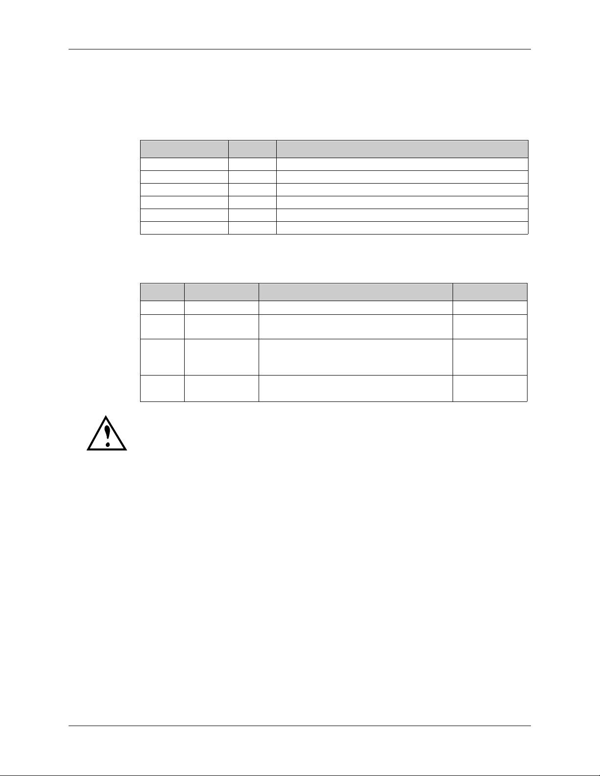
Display Ratio Display Ratio Display Ratio
OFF 1:1 2 2:1 4 6:1
1 1.4:1 3 3:1 5 Infinity:1
Volume
When the
volume by connecting a volume-type pedal to the
VOLUME PEDAL ON/OFF control is turned on, you can control
PEDAL 1 jack on the rear
panel (or via MIDI using controller 7). You can set this parameter to
control volume either before it goes into the Preamp (PrE) or as it comes
out of the Preamp (PSt, which stands for ÒpostÓ). For more info on using
pedals, see page 17.
Distortion Box
This provides various types of distortion, such as those commonly found
in pedal boxes. These offer different characteristics than overdriving the
preamp. The
DISTORTION BOX parameter lets you choose from the
following types:
Display Tone Physical model of...
1-X Bright
2-X Medium Tube Screamer
3-X Dark
4-X Bright
5-X Medium Rat
6-X Dark
7-X Bright
8-X Medium Big Muff Pi
9-X Dark
X can be set from 0 to 9, where 0 is the minimum amount of distortion and
9 is the maximum amount.
AxSys 212 User Manual 23
Page 24

Chapter 3: Description of Features
If the DISTORTION BOX ON/OFF parameter is turned off, the Distortion Box effect
will not be heard (see page 35). If you adjust the
display will flash OFF twice to indicate it is turned off.
The DISTORTION BOX parameter is disabled when the Acoustic Sim Preamp type
is selected (see page 28). If you attempt to modify it, the display will temporarily
---
read
.
Wah
The Wah effect creates a unique tone by sweeping the frequency of a
resonant filter.
Parameter Range Description
Wah Type Off, 1Ð4,
Wah Depth 00Ð99 Controls the amount of Wah (see below).
The WAH PEDAL TYPE parameter lets you choose from 5 settings:
DISTORTION BOX parameter, the
Selects the type of Wah effect (see table below).
5ÐX (0-23)
Display Wah Type Description
1 Wah Pedal Use an expression pedal connected to the PEDAL 2 jack to
control the wah effect.
2 Auto-Wah Creates an automatic wah by opening the filter in response
to the volume of the input.
3 Rando-Wah Creates an automatic wah by randomly changing the filter
every time a new note is played.
4 Sample/Hold Creates automatic wah effect by stepping the filter through
various non-contiguous settings.
5-X Mod Assign Routes PEDAL 2 to a selected parameter; lets you use your
Wah pedal to control something other than the wah effect.
If no pedals are connected to either PEDAL 1 (VOLUME) or PEDAL 2 (WAH) jacks
and the WAH TYPE parameter is set to either 1 or 5, the Wah will be turned off
automatically. Also, since you can control the Wah via MIDI (using controller 3),
the Wah effect will automatically turn on if controller 3 messages are received by
the AxSys.
WAH DEPTH parameter determines how prominent the Wah effect is.
The
When using the Sample/Hold Wah type 4, it controls the speed. When
using the Mod Assign Wah type 5, it controls the depth of the pedalÕs
control over the parameter being modulated. For more information on
using pedals, see page 17.
24 AxSys 212 User Manual
Page 25

Description of Features: Chapter 3
The following parameters are available for modulating:
Display Parameter Display Parameter Display Parameter
5-0 Preamp Bass 5-8 Presence 516 Reverb Decay
5-1 Preamp Middle 5-9 Tremolo Speed 517 Reverb Level
5-2 Preamp Treble 510 Tremolo Depth 518 Drive
5-3 EQ 80Hz 511 Delay Feedback 519 Bass
5-4 EQ 240Hz 512 Delay Level 520 Mid
5-5 EQ 750Hz 513 Chorus Speed 521 Treble
5-6 EQ 2200Hz 514 Chorus Feedback 522 Gain
5-7 EQ 6600Hz 515 Chorus Level 523 Delay/Reverb
As you scroll through the available parameters, a pair of LEDs (one in the
Edit Row column, the other above the Control Knobs) will flash to indicate
the selected parameterÕs location in the parameter matrix.
When using Wah type 5 (Mod Assign) it is important that you set the parameter
being modulated to its minimum, or 00 setting. This is because PEDAL 2 will only
provide positive modulation. This means the current setting of the modulated
parameter is the ÒbaselineÓ or starting point of modulation (i.e. when the pedal is
all the way heel down).The
WAH DEPTH will determine what the maximum of the
modulated parameter will be when the pedal is all the way forward (toe down).
99
P
a
r
a
m
e
t
e
r
V
a
l
u
e
00
Down Up
(Heel) (Toe) (Heel) (Toe)
When the modulated parameterÕs
setting is at its minimum or 00 value, and
the
WAH DEPTH
Pedal 2 takes full control over its effect.
99
P
a
r
a
m
e
t
e
r
V
a
l
u
e
00
Down Up
(Heel) (Toe) (Heel) (Toe)
When the modulated parameterÕs
setting is at its halfway or 50 value, and
the
WAH DEPTH
Pedal 2Õs range goes from 50 to 99.
Pedal Position
parameter is set to 50,
Pedal Position
parameter is set to 99,
99
P
a
r
a
m
e
t
e
r
V
a
l
u
e
00
Down Up
When the modulated parameterÕs setting
is at its halfway or 50 value, and the
parameter is set to 99, Pedal 2Õs
DEPTH
range goes from 50 to 99. However, it
reaches 99 when the Pedal is at its mid-
way point; this means the Pedal has no
effect from mid-way to toe-down.
Pedal Position
99
P
a
r
a
m
e
t
e
r
V
a
l
u
e
00
Down Up
When the modulated parameterÕs
setting is at its minimum or 00 value, and
the
Pedal 2Õs control over its effect is limited.
WAH DEPTH
WAH
Pedal Position
parameter is set to 50,
99
P
a
r
a
m
e
t
e
r
V
a
l
u
e
00
Down Up
(Heel) (Toe)
When the modulated parameterÕs
setting is at its maximum or 99 value,
Pedal 2 will have no control over its
effect, regardless of the
Pedal Position
parameterÕs setting.
WAH DEPTH
AxSys 212 User Manual 25
Page 26
Chapter 3: Description of Features
Auto Volume Attack
The Auto Volume effect automatically Òramps upÓ the signal level. It
simulates the ÒbowedÓ playing technique in which the volume is turned
down at the beginning of each note so that the attack portion of the signal
is not heard, and then the volume is gradually raised.
Parameter Range Description
Auto-Volume Off, 01-99 Adjusts the rate of the ramping of volume.
Preamp Controls
TubeTone technology is what makes the AxSys so versatile, and allows it
to accurately recreate the classic tone of a variety of guitar amps.
Parameter Range Description
Preamp Type
Drive 00Ð99 Controls the volume of the signal going into the Preamp;
Preamp Bass 00Ð99 Adjusts the tone for the low frequency range of the
Preamp Middle 00Ð99 Adjusts the tone for the middle frequency range of the
Preamp Treble 00Ð99 Adjusts the tone for the high frequency range of the
Bright Switch On, Off When on, a sharper and brighter sound is produced.
Presence 00Ð99 Provides a boost of the high-mid frequencies.
Output Level 00Ð99 Controls the volume of the PreampÕs output. This sets
(see page 27)
Selects the type of amp tone.
use higher levels to create distortion.
Guitar signal before it goes into the Preamp.
Guitar signal before it goes into the Preamp.
Guitar signal before it goes into the Preamp.
the amount of signal passed to the rack effects section.
Drive
This controls the level going into the Preamp. Typically this control allows
you to overdrive the tubes in a typical guitar amp. The AxSys simulates
this phenomenon with astounding accuracy for each of its Preamp Types.
If the DRIVE ON/OFF parameter is turned off, the Drive effect will not be heard
(see page 35). If you adjust the DRIVE knob, the display will flash OFF twice to
indicate it is turned off.
The DRIVE control is disabled when the Acoustic Sim Preamp type is selected. If
you attempt to modify it, the display will temporarily read
---
.
Preamp EQ
Equalization, or EQ, provides the ability to control timbre, or coloration, of
an audio signal. Before the GuitarÕs signal goes into the Preamp section, it
passes through the Preamp EQ. Three parameters are available, including:
PREAMP BASS, PREAMP MIDDLE and PREAMP TREBLE.
26 AxSys 212 User Manual
Page 27
Description of Features: Chapter 3
The PREAMP BASS, PREAMP MIDDLE and PREAMP TREBLE controls are disabled
when the Acoustic Sim Preamp type is selected. If you attempt to modify these
---
parameters, the display will temporarily read
.
Preamp Type
The PREAMP TYPE lets you choose from the following preamp tones:
Display Preamp Type Physical model of...
1-0 Clean AxSys Clean
1-1 JC120 Normal
1-2 JC120 Bright
1-3 JC120 Jazz Tone
2-0 Tweed Fender Bassman Clean
2-1 Fender Bassman Crunch
2-2 Fender Bassman Overdrive
2-3 Fender Twin Reverb Clean
2-4 Fender Twin Reverb Crunch
2-5 Fender Twin Reverb Overdrive
2-6 Matchless Chieftain Clean
2-7 Matchless Chieftain Crunch
2-8 Matchless Chieftain Overdrive
3-0 British Marshall JTM45 (ca. 1965) Clean
3-1 Marshall JTM45 (ca. 1965) Crunch
3-2 Marshall 100-watt ÒPlexiÓ Crunch
3-3 Marshall JCM800 Brilliant Ch. Clean
3-4 Marshall JCM800 Brilliant Ch. Crunch
3-5 Marshall JCM800 Brilliant Ch. Overdrive
3-6 Marshall JCM800 w/ Master Vol. Crunch
3-7 Marshall JCM800 w/ Master Vol. Overdrive
3-8 Vox AC 30 non-Top Boost (ca. 1960) Clean
3-9 Vox AC 30 non-Top Boost (ca. 1960) Crunch
310 Vox AC 30 non-Top Boost (ca. 1960) Overdrive
311 Vox AC 30 with Top Boost (ca. 1964) Clean
312 Vox AC 30 with Top Boost (ca. 1964) Crunch
4-0 Hybrid AxSys Vintage
4-1 Soldano Super Lead Overdrive Crunch
4-2 Soldano Super Lead Overdrive Overdrive
4-3 Soldano Super Lead Overdrive Lead
4-4 Boogie Dual Rectifier Clean/Blues
4-5 Boogie Dual Rectifier Crunch
4-6 Boogie Dual Rectifier Modern High Gain
4-7 Arbiter Fuzz Face
5-0 Acoustic Sim Acoustic #1
5-1 Acoustic #2
AxSys 212 User Manual 27
Page 28

Chapter 3: Description of Features
Acoustic Simulator
The AxSys provides two different Acoustic Simulator Preamp types.
These simulate the sound of an acoustic guitar with a pickup or a piezo
transducer in the saddle.
TIP
For the best simulation, always select the pickup closest to the
guitarÕs neck. Single coil pickups tend to sound better because of
their bright tone; and a bright, stringy sound is the signature of an
acoustic guitar. If you are using a humbucking pickup, try using a
coil splitter to disable some of the coils and brighten the sound up.
When either of the Acoustic Sim Preamp types are selected, the following
parameters will be disabled:
Noise Gate On/Off Noise Gate Threshold Noise Gate Decay
Preamp Bass Preamp Middle Preamp Treble
Bright Switch Preamp Output Level Distortion Box
Distortion Box On/Off Rando-Wah Sample/Hold Wah
Drive Drive On/Off
Bright Switch
The
BRIGHT SWITCH parameter is your basic brightness booster.
The BRIGHT SWITCH control is disabled when the Acoustic Sim Preamp type is
selected. If you attempt to modify it, the display will temporarily read
---
.
Presence
The
PRESENCE parameter provides a boost of the high-mid frequencies,
and raises the signal level a bit. It can be adjusted between 00 and 99.
Rack Effects
5-Band Graphic EQ
A graphic EQ is a set of bandpass filters used for general tonal shaping, as
in many home stereos. The 5 bands in the Graphic EQ of the AxSys 212 are
about an octave and a fifth apart at
Each of these may be set between -19 and +19 dB, providing a cut or boost,
of their respective frequency range.
Parameter Range Description
80Hz -19 to 19 Cuts or boosts the frequency range centered at 80Hz.
240Hz -19 to 19 Cuts or boosts the frequency range centered at 240Hz.
750Hz -19 to 19 Cuts or boosts the frequency range centered at 750Hz.
2200Hz -19 to 19 Cuts or boosts the frequency range centered at 2200Hz.
6600Hz -19 to 19 Cuts or boosts the frequency range centered at 6600Hz.
80Hz, 240Hz, 750Hz, 2200Hz and 6600Hz.
28 AxSys 212 User Manual
Page 29
Description of Features: Chapter 3
If the EQ ON/OFF parameter is turned off, the Graphic EQ will not have any effect
on the Sound (see page 35). If you adjust any of the Graphic EQ parameters, the
display will flash OFF twice to indicate it is turned off.
Tremolo
Mono Tremolo2 fluctuates loudness, and Stereo Tremolo alternates
loudness in opposite channels. On slow speeds with a soft shape, stereo
tremolo provides continuous panning. At low to moderate depths and
moderate speeds, itÕs like the sound of classic electric piano tremolo.
Parameter Range Description
Tremolo Type Off, 1 to 3 Selects the type of Tremolo effect (see below).
Tremolo Speed 00 to 99 Controls the rate at which the sound changes amplitude.
Tremolo Depth 00 to 99 Controls how strong the tremolo will be.
Tremolo Shape 00 to 99 Selects either soft (gradual) or hard (drastic) transitions.
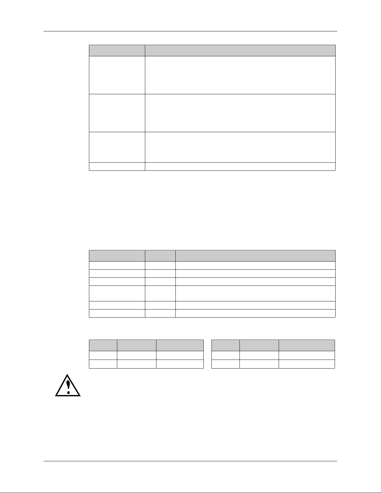
The TREMOLO TYPE lets you choose from the following Tremolo types:
Display Tremolo Type Description
OFF No Tremolo Tremolo is disabled.
1 Mono Tremolo Provides the classic Tremolo useful in recreating the
sound of older guitar amps.
2 Stereo Tremolo
at 90°
3 Stereo Tremolo
at 180°
100% 100%
Left Right
Mono Tremolo
This two channel Tremolo has the left and right channels
close together; i.e. when one is on, the other is 1/2 on, and
when one is off, the other is 1/2 off.
This two channel Tremolo has the left and right channels
perfectly out of phase; i.e. when one is on the other is off.
100% 50%
Left Right
Stereo Tremolo 90¡
100% 0%
Left Right
Stereo Tremolo 180¡
If the TREM/CHORUS ON/OFF parameter is turned off, the Tremolo effect will not
be heard (see page 35). If you adjust any of the Tremolo parameters, the display
will flash OFF twice to indicate it is turned off.
The Tremolo parameters are disabled when the Rotary type of Chorus is selected.
If you attempt to modify the Tremolo parameters, the display will temporarily
---
read
.
2
Some guitar amps mistakenly call this ÒvibratoÓ, but this is incorrect. Vibrato is actually
the fluctuation of pitch, whereas tremolo is a fluctuation of volume.
AxSys 212 User Manual 29
Page 30
Chapter 3: Description of Features
Delay
Delay provides repetition, or echo, of a signal. By adding feedback, the
delayed signal can repeat many times, with each successive repetition
softer than its predecessor.
Parameter Range Description
Delay Type 1 to 4 Selects the type of Delay (see below).
Main Delay Time 00 to 99 Controls the speed of the delay (see chart on next page).
Delay Time Offset 00 to 99 Offsets the left & right channels (see page 31).
Delay Feedback 00 to 99 Controls the number of repetitions.
Dynamic Delay 00 to 99 Threshold above which Delay is muted.
Delay Level 00 to 99 Controls the output level of the Delay effect.
The DELAY TYPE parameter lets you choose from the following Delay
types:
Display Delay Type Description Max. Delay
1 Mono Delay Provides a single delay of signal. 1250 mS
2 Stereo Delay Provides two discrete delays; one to the
3 Ping Pong
Delay
4-0 to
4-9
Multi Tap
Delay
left channel, the other to the right channel.
This two channel delay has the output of
each channel flowing into the other, going
back and forth like a game of ping-pong.
Provides 5 delays at once, with 10
configurations (see below).
625 mS
625 mS
n/a
TIP
If the DELAY ON/OFF parameter is turned off, the Delay effect will not be heard
(see page 35). If you adjust any of the Delay parameters, the display will flash
OFF twice to indicate it is turned off.
The Stereo Delay and Ping Pong Delay types will sound even wider
when the
CABINET SPREAD parameter is turned on. See page 35 for
more information.
Multi Tap Delay
This is like having five delays at once, each having a different delay time,
volume and panning. There are 10 Multi Tap configurations (4-0 through
4-9), each with its own rhythm. The
MAIN DELAY TIME parameter lets you
control the relative ÒspreadÓ, or tempo, of all taps at once while keeping
the same rhythm. When set to low numbers, the taps are closer together; at
higher values, the taps become spaced further apart. The
DELAY FEEDBACK
parameter controls all taps at once, making it easy to adjust the total
number of ÒechoesÓ.
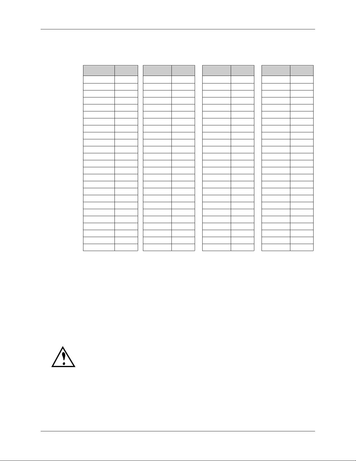
Main Delay Time
0 is the shortest delay time and 99 is the longest. This range is exponential,
which means that the lower numbers take small steps, and the bigger
30 AxSys 212 User Manual
Page 31
Description of Features: Chapter 3
numbers take bigger steps. The following table shows the equivalent to
each setting of the delay time in milliseconds when using the Mono Delay:
Display mS Display mS Display mS Display mS
0 0017.0 25 0236.8 50 0517.7 75 0889.9
1 0021.9 26 0254.1 51 0528.5 76 0906.0
2 0026.8 27 0271.5 52 0539.3 77 0922.2
3 0031.7 28 0288.8 53 0550.1 78 0938.4
4 0036.6 29 0306.2 54 0560.9 79 0954.6
5 0041.5 30 0323.6 55 0571.7 80 0970.8
6 0046.4 31 0334.4 56 0582.5 81 0986.9
7 0051.3 32 0345.2 57 0593.2 82 1003.1
8 0056.2 33 0355.9 58 0604.0 83 1019.3
9 0061.1 34 0366.7 59 0614.8 84 1035.5
10 0066.0 35 0377.5 60 0625.6 85 1051.7
11 0074.4 36 0388.3 61 0636.4 86 1067.8
12 0082.8 37 0399.1 62 0647.2 87 1084.0
13 0091.2 38 0409.9 63 0663.3 88 1100.2
14 0099.6 39 0420.6 64 0679.5 89 1116.4
15 0108.0 40 0431.4 65 0695.7 90 1132.6
16 0116.4 41 0442.2 66 0711.9 91 1146.5
17 0124.8 42 0453.0 67 0728.1 92 1160.4
18 0133.2 43 0463.8 68 0744.2 93 1174.4
19 0141.6 44 0474.6 69 0760.4 94 1188.4
20 0150.0 45 0485.4 70 0776.6 95 1202.3
21 0167.3 46 0496.2 71 0792.8 96 1216.3
22 0184.7 47 0507.0 72 0809.0 97 1230.2
23 0202.1 48 0517.7 73 0825.1 98 1244.2
24 0219.4 49 0528.5 74 0841.3 99 1258.1
Note: When using the Stereo Delay, all delay times are halved. Example: If
MAIN DELAY TIME parameter is set to 62 while using the Stereo Delay,
the
the delay time would actually be 0323.6 mS.
Tap Tempo
An alternative way to adjust the MAIN DELAY TIME parameter is by
repeatedly pressing the
TUNER button). The AxSys will gauge the time between each press and
immediately set the
TAP TEMPO button (which also happens to be the
MAIN DELAY TIME parameter to the equivalent value,
and show this value in the display.
The TUNER button will only function as a TAP TEMPO button while you are
editing the Delay parameters (i.e., the Delay Edit Row is selected). Otherwise,
pressing this button will select Tuner mode.
Delay Time Offset
DELAY TIME OFFSET parameter (00 - 99) provides a different function
The
depending on the selected Delay Type:
AxSys 212 User Manual 31
Page 32
Chapter 3: Description of Features
Delay Type DELAY TIME OFFSET Function
Mono Delay Offsets the panning of the input signal from the delayed signal
Stereo Delay Offsets the right channelÕs delay signal from the left channel. This
Ping Pong Delay Controls the ÒrhythmÓ spacing of the two delay signals. When set
Multi Tap Delay Disabled.
Dynamic Delay
The
DYNAMIC DELAY parameter adjusts the loudness of the delay based on
how loud you are playing. It is a threshold setting, similar to the threshold
setting of a noise gate. When set to a high value, the delay is softer while
you play, which helps avoid that unwanted ÒmuddyÓ sound. When you
stop playing, it gets louder.
between the left and right channels. When set to 0, both signals are
centered between the left and right channels, creating a mono
image; when set to 99, the direct signal is routed to the right
channel, while the delayed signal goes to the left channel.
is done by first setting the MAIN DELAY TIME, for example, to
400 mS, and then using Delay Offset to offset the right channel
relative to left. When set to 00, the right side is equal to the left side;
when set to 50, the right side is 50% less than the left side.
to 50, the rhythm is equal between the right and the left side; when
set to 25, the rhythm sounds as if you were playing on beats 1 and
4 (in 4/4 time, of course).
Chorus
Parameter Range Description
Chorus Type 1 to 4 Selects the type of Chorus (see below).
Chorus Speed 00 to 99 Controls the speed of the Chorus effect.
Chorus Depth 00 to 99 Controls the depth of the Chorus effect.
Chorus Feedback 00 to 99 Controls the amount of the ChorusÕ output being
fedback into its input.
Chorus Shape 1 to 4 Selects either a Sine wave or Square wave shape.
Chorus Level 00 to 99 Controls the output level of the Chorus effect.
The CHORUS TYPE lets you choose from the following Chorus types:
Display Type Description Display Type Description
1 Chorus (see page 41) 3 Phase (see page 42)
2 Flange (see page 42) 4 Rotary (see page 42)
If the TREM/CHORUS ON/OFF parameter is turned off, the Chorus effect will not
be heard (see page 35). If you adjust any of the Chorus parameters, the display will
flash OFF twice to indicate it is turned off.
Chorus. The Chorus effect produces a pitch detuned version of you guitar,
and combines it with the guitar signal. The amount of detuning is
controlled by the
by the
CHORUS SPEED. The CHORUS FEEDBACK can emphasize the effect by
CHORUS DEPTH, and the speed of detuning is controlled
32 AxSys 212 User Manual
Page 33
Description of Features: Chapter 3
causing the detuned signal to be re-detuned. CHORUS SHAPE selects
between a sine wave, for smooth sweeping pitch, or a square wave, for a
more abrupt shift in pitch.
In the case of a Stereo Chorus, the left channel is detuned sharp, the right
is detuned flat, and vice versa. This causes the effect to become more
pronounced and dramatic.
3
Flange. Flanging
mixed with the original sound to produce the ÒswishingÓ or ÒtunnelingÓ
sound. Stereo Flange sweeps one channel up while the other sweeps
down.
When using the Flange type with the Square waveform shape, the Square shape
will actually provide a Triangle waveform shape.
produces a Òjet airplaneÓ-like sound. A delayed signal is
TIP
TIP
The Stereo Chorus and Stereo Flange types will sound even wider
when the
Phase. Another popular effect is the Phase Shifter or Phasor. The Phasor
shifts the phase of different frequencies in different amounts, resulting in a
comb filter effect when combined with the dry signal.
Because the Phase type of Chorus is mono only, the CHORUS SHAPE parameter
can only be set to 1 (Mono Sine) or 3 (Mono Square) when the Phase type is
selected. Also, the Square shape will actually provide a more useful sounding
Triangle waveform shape.
Rotary. This effect was extremely popular during the 1960Õs and was
achieved by mechanically rotating the speakers to produce complex
timbral changes. The Leslie speaker system is best known for its rotary
speaker architecture. It is most often used with Hammond-type organs,
but is occasionally used for guitar amplification as well.
When changing between Sounds that use a slow to fast Rotary
Speed, the Rotary effect will produce authentic ramping between
the two speeds, just like the real thing.
CABINET SPREAD parameter is turned on (see page 35).
The CHORUS SHAPE parameter is disabled when the Rotary type is selected. If you
attempt to modify this parameter, the display will temporarily read
3
First used in the 1960s, flanging was achieved by the use of two tape recorders that
would record and play back the same program in synchronization. By slowing down one
tape machine, and then letting it catch up with the other, different phase cancellations
would occur at different frequencies. Since the slowing down of the tape machines was
done by hand pressure against the flanges of the tape supply reels, the term ÒFlangingÓ
came into being.
AxSys 212 User Manual 33
---
.
Page 34
Chapter 3: Description of Features
Reverb
Parameter Range Description
Reverb Type 1 to 5 Selects the type of Reverb (see below).
Predelay 00 to 99 Controls the delay of the first instance of reverberation,
Reverb Decay 00 to 99 Controls how long it takes for the Reverb to die away.
Reverb Tone 00 to 99 Controls the ReverbÕs tone.
Reverb Diffusion 00 to 99 Determines the ÒthicknessÓ of the reverb (see below).
Reverb Level 00 to 99 Controls the output level of the Reverb effect.
Reverb is made up of a large number of distinct echoes, called reflections.
In a natural acoustic space, each reflectionÕs amplitude and brightness
decays over time. This decay is influenced by the room size, the location of
the sound source in the room, the hardness of the walls, and other factors.
REVERB TYPE parameter lets you choose from these Reverb types:
The
Display Reverb Type Description
1
2 Dark Room Recreates the ambiance of a small room with many
3 Bright Room Similar to Dark Room, but with more high frequencies.
4 Dark Hall Recreates the ambiance of a large auditorium or concert
5 Bright Hall Similar to Dark Hall, but with more high frequencies.
Spring
so that the dry signal stands out from the Reverb effect.
4
Produces a ringing, resonant sound, which is a
requirement for vintage guitar applications.
reflective surfaces, but with a dark tone.
hall that has a lot of space to fill, but with a dark tone.
Diffusion
Diffusion determines the ÒthicknessÓ of the reverb sound by adding more
reflections to the reverbÕs decay. At low settings, you can hear the
individual echoes that make up the overall reverb sound. At higher
settings, the echoes increase and blend, washing out the reverbÕs decay.
DIFFUSION OF 0 DIFFUSION OF 99
L
E
V
E
L
TIME
Fewer reflections More reflections
L
E
V
E
L
TIME
If the REVERB ON/OFF parameter is turned off, the Reverb effect will not be heard
(see page 35). If you adjust any of the Reverb parameters, the display will flash
OFF twice to indicate it is turned off.
4
Sorry. Because this is a physically modeled spring reverb, you canÕt get the Òthunder
crashÓ effect when you bump into the amp.
34 AxSys 212 User Manual
Page 35

Description of Features: Chapter 3
Cabinet Type
This effect simulates various types of speaker enclosures. You may choose
among the following enclosure simulators:
# in Display Modeled after...
OFF
1-0
1-1
1-2
2-0
2-1
2-2
3-0
3-1
3-2
4-0
4-1
4-2
AxSys 2 x 12"
2 x 10" Music Man cabinet
2 x 10" Blues cabinet
2 x 10" (Comb filter effect)
2 x 12" Fender Twin Reverb
2 x 12" JC-120
2 x 12" Matchless with Celestion Vintage 30Õs
4 x 10" Fender Bassman
4 x 10" Peavey Classic 50
4 x 10" Custom
4 x 12" Marshall slant cabinet with Celestion ÒgreenbacksÓ
4 x 12" Marshall slant cabinet with Celestion Vintage 30Õs
4 x 12" Custom
Cabinet Spread
This effect is useful for ÒwideningÓ a flat sound to produce more depth
and color. When turned on, it creates the illusion that sound is emanating
in stereo from a pair of speakers placed somewhere around the listener. By
doing so, the sound appears spatially distributed, and takes on a lively
new ambiance.
TIP
Cabinet Spread is especially effective when using a stereo effect,
such as the Stereo Chorus, Stereo Flange, Stereo Delay, Ping Pong
Delay and Reverb.
FX On/Off
These parameters provide a convenient method of turning on and off a
particular effect without having to alter its settings.
Parameter Range Description
Distortion Box On/Off On, Off Turns the Distortion Box effect on or off.
Drive On/Off On, Off Turns the PreampÕs Drive control on or off. When
EQ On/Off On, Off Turns the Graphic EQ on or off.
Trem/Chorus On/Off On, Off Turns the Tremolo and Chorus effects on or off.
Delay On/Off On, Off Turns the Delay effect on or off.
Reverb On/Off On, Off Turns the Reverb effect on or off.
turned on, the DRIVE controlÕs current setting is
used. When off, it is the equivalent of turning the
DRIVE control all the way down to 00.
AxSys 212 User Manual 35
Page 36

Chapter 3: Description of Features
If an effect doesnÕt seem to be working, be sure to check if the effect is turned on in
FX ON/OFF Edit Row. If you adjust any parameter of an effect that is turned
the
off, the display will flash OFF twice to indicate it is turned off.
TIP
TIP
Since all of these parameters are the Òon/offÓ type, itÕs easy to see at a glance what
all 6 settings are (i.e. which effects are on or off), since each Control KnobÕs LED
will either be on or off.
All of the parameters found on the FX ON/OFF Edit Row, are available on the
optional AxSys Remote Pedal Board for easy access.
The DISTORTION BOX ON/OFF and DRIVE ON/OFF controls are disabled when
the Acoustic Sim Preamp type is selected. If you attempt to modify them, the
display will temporarily read
Aux Controls
The Aux Input can be used for a second signal, such as a microphone,
drum machine or acoustic guitar.
Parameter Range Description
Aux Input Mix 00 to 99 Controls the mix of the Aux Input signal relative to the
Aux Input Bass -50 to +50 Provides a boost or cut of low frequencies to the Aux
Aux Input Treble -50 to +50 Provides a boost or cut of high frequencies to the Aux
Aux Input Reverb 00 to 99 Controls the amount of Aux Input signal going to the
---
.
Guitar Input signal.
Input signal.
Input signal.
Reverb effect.
Aux Input Mix
This controls the mix of the Aux Input signal relative to the Guitar Input
signal. It can be set between 0 and 99. When set to 0, the Aux Input signal
is not heard at all. When set to 99, the Aux Input signal is mixed with the
Guitar Input signal at maximum volume.
Aux Input Bass
This is a low frequency cut or boost control for the Aux Input signal. It can
be set between -50 and 50. Negative values decrease the bass, while
positive values increase them; a setting of 0 leaves the bass response flat.
Aux Input Treble
This is a high frequency cut or boost control for the Aux Input signal. It
can be set between -50 and 50. Negative values decrease the treble, while
positive values increase them; a setting of 0 leaves the treble response flat.
36 AxSys 212 User Manual
Page 37

Aux Input Reverb
This controls the amount of reverb that is added to the Aux Input signal.
When set to 0, no reverb is added and the Aux Input signal is ÒdryÓ. When
set to 99, the reverb is added at its maximum level and the Aux Input
signal is ÒwetÓ.
Global Controls
The following four controls are found on the far right end of the first top
two Edit Rows. As their name ÒGlobalÓ implies, these four parameters are
set once for all Sounds; i.e. their settings are static and do not change from
one Sound to another.
Parameter Range Description
MIDI Channel 01 to 16 Selects the basic MIDI channel.
Transmit Sounds 01A to 32D,
Gate/Hum Per
Sound
Aux Per Sound Snd, All Determines whether the Aux Input parameters will
Description of Features: Chapter 3
Lets you transmit one or all User Sounds via the
Edit, All
Snd, All Determines whether the Noise Gate and Hum
MIDI OUT connector.
Canceller parameters will change when a new Sound
is selected.
change when a new Sound is selected.
MIDI Channel
The
MIDI CHANNEL parameter determines which of the 16 available MIDI
channels is used to send and receive program changes and controller
messages (controller 7 for Volume, controller 3 for Wah). It can be set
between 1 and 16.
Transmit Sounds
TRANSMIT SOUNDS parameter lets you transmit either a single User
The
Sound or all User Sounds in memory via the
MIDI OUT connector. This
information can be sent to a MIDI storage device, such as a computer
running a sequencer or editor/librarian software, or to another AxSys 212.
Display Transmitted via MIDI
01A to 32d Any single Sound in the User Bank (01-32, A-D)
Edt The current Sound being edited
ALL All 128 Sounds in the User Bank
Use the TRANSMIT SOUNDS parameter to select what you want to transmit.
You can choose any User Sound from 01A to 32d, or Edt (the current
Sound in the edit buffer) or ALL (all Sounds in the User Bank). Once
youÕve made your selection, press the
STORE button to execute the
transmission; the display will temporarily read trA.
AxSys 212 User Manual 37
Page 38

Chapter 3: Description of Features
Gate/Hum Per Sound
This function determines whether the Noise Gate and Hum Canceller
parameters will change when a new Sound is selected. These parameters
include:
and
NOISE GATE ON/OFF, NOISE GATE THRESHOLD, NOISE GATE DECAY,
HUM CANCELLER. If you want to use the same settings for these
parameters, regardless of which Sound you use, set this parameter to
ALL. If, however, you have stored different settings for these parameters
within certain Sounds and would like those settings to be recalled
whenever those Sounds are selected, set this parameter to Snd.
Display Description
Snd The Noise Gate and Hum Canceller parameters will change when a
ALL The Noise Gate and Hum Canceller parameters will not change when a
Aux Per Sound
new Sound is selected to the stored settings for that Sound.
new Sound is selected. In other words, the Noise Gate and Hum
Canceller parametersÕ current settings will be used for all Sounds.
This function determines whether or not the Aux input parameters will
change when a new Sound is selected. These parameters include: AUX
INPUT MIX, AUX INPUT BASS, AUX INPUT TREBLE, and AUX INPUT REVERB. If
you would like to use the same settings for these parameters, regardless of
which Sound you use, set this parameter to ALL. If, however, you have
stored different settings for these parameters within certain Sounds and
would like those settings to be recalled whenever those Sounds are
selected, set this parameter to Snd.
Display Description
Snd The Aux Input parameters will change when a new Sound is selected
to the stored settings for that Sound.
ALL The Aux Input parameters will not change when a new Sound is
selected. In other words, the Aux Input parameterÕs current settings
will be used for all Sounds.
38 AxSys 212 User Manual
Page 39
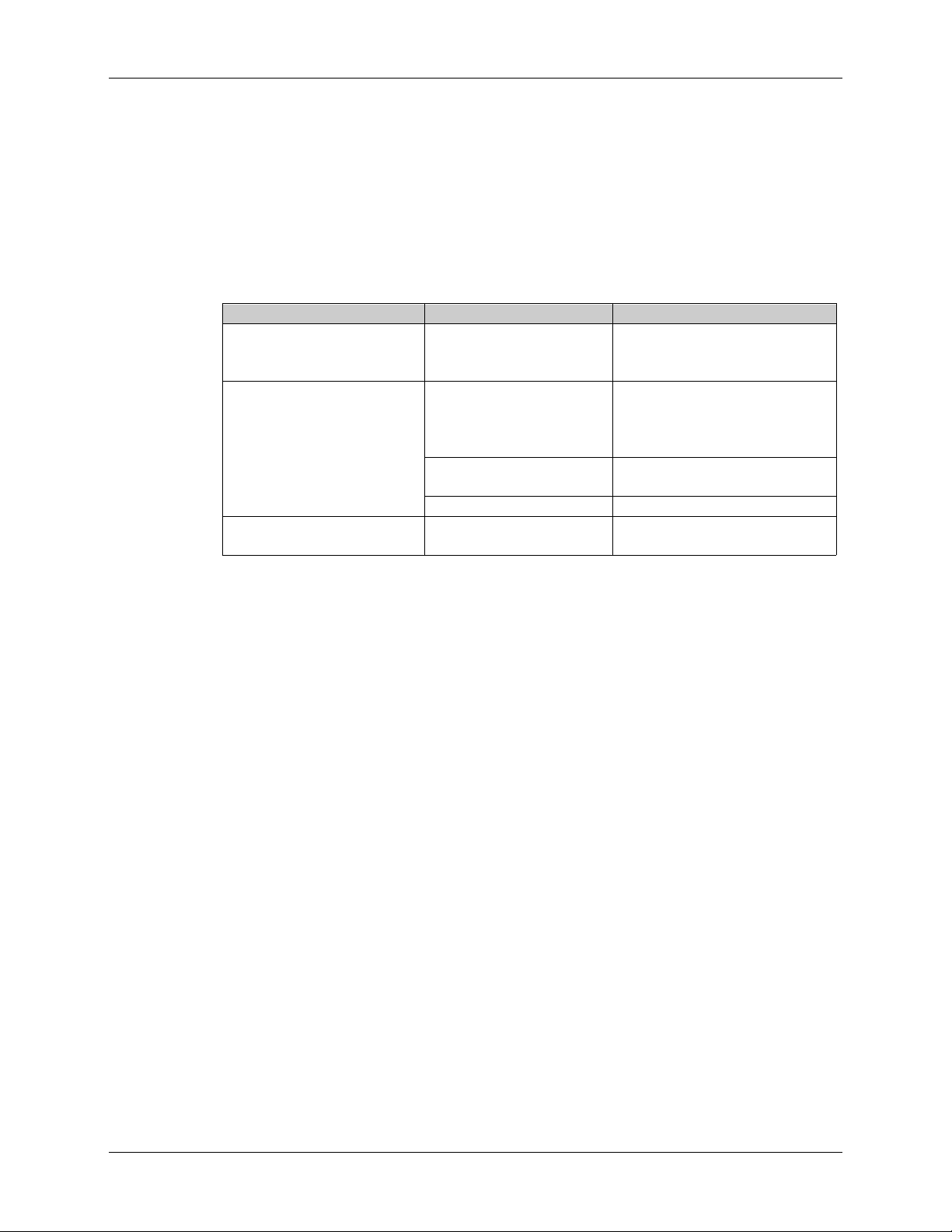
APPENDICES
Appendix I: Troubleshooting
If you are experience problems while operating the AxSys 212, please use
the following table to locate possible causes and solutions before
contacting Line 6 customer service for assistance.
Symptom Cause Solution
The display does not light
when the POWER switch
is turned on.
No sound. Speakers are not
Control Knobs wonÕt
change parameter settings.
No power. Check that the power cable is
connected to amp.
Bad cable. Check your guitar cables;
Volume is turned down. Raise the MASTER knob.
Compare mode is turned
on (C appears in display)
Appendices
plugged in properly.
Connect the speaker cables to
the rear panel LEFT
SPEAKER and RIGHT
SPEAKER jacks
replace if necessary.
Press COMPARE to exit
Compare mode.
Appendix II: Maintenance & Service
Cleaning
Disconnect the AC cord, then use a damp cloth to clean the ampÕs metal
and plastic surfaces. For heavy dirt, use a non-abrasive household cleaner
such as Formula 409 or Fantastik. DO NOT SPRAY THE CLEANER
DIRECTLY ONTO THE FRONT OF THE UNIT AS IT MAY DAMAGE
THE LUBRICANTS USED IN THE SWITCHES AND CONTROLS! Spray
onto a cloth, then use the cloth to clean the unit.
Maintenance
Here are some tips for preventive maintenance.
¥ Periodically check the AC cord for signs of fraying or damage.
¥ Place a dust cover over the AxSys 212 when it is not in use.
Refer All Servicing to Line 6
We believe that the AxSys 212 is one of the most reliable amps that can be
made using current technology, and should provide years of trouble-free
use. However, should problems occur, DO NOT attempt to service the
amp yourself. The full AC line voltage, as well as high voltage/high
current DC voltages, are present at several points within the chassis.
Service on this product should be performed only by qualified technicians.
THERE ARE NO USER-SERVICEABLE PARTS INSIDE.
AxSys 212 UserÕs Manual 39
Page 40

Appendices
Obtaining Repair Service
Before contacting Line 6, check over all your connections, and make sure
youÕve read the manual.
Customers in the USA:
If the problem persists, call Line 6 at (310) 390-5956 and request the
Product Support department. Talk the problem over with one of our
technicians; if necessary, you will be given a Return Authorization (RA)
number and instructions on how to return the unit. All units must be
shipped prepaid and COD shipments will not be accepted.
For prompt service, indicate the RA number on the shipping label. If you
do not have the original packing, ship the amp in a sturdy carton, with
shock-absorbing materials such as styrofoam pellets (the kind without
CFCs, please) or Òbubble-packÓ surrounding the unit. Shipping damage
caused by inadequate packing is not covered by the Line 6 warranty.
Tape a note to the top of the unit describing the problem, include your
name and a phone number where Line 6 can contact you if necessary, as
well as instructions on where you want the product returned. Line 6 will
pay for standard one-way shipping back to you on any repair covered
under the terms of this warranty. Next day service is available for a
surcharge.
Field repairs are not normally authorized during the warranty period, and
repair attempts by unqualified personnel may invalidate the warranty.
Service address for customers in the USA:
Line 6 Product Support
11260 Playa Court
Culver City, CA 90230
Customers outside the USA:
Contact your local Line 6 dealer for warranty assistance. The Line 6
Limited Warranty applies only to products sold to users in the USA and
Canada. Customers outside of the USA and Canada are not covered by
this Limited Warranty and may or may not be covered by an independent
distributor warranty in the country of sale. Do not return products to the
factory unless you have been given specific instructions to do so.
40 AxSys 212 UserÕs Manual
Page 41

Appendix III: Tube Replacement Schedule
Yeah, right!! You gotta be kidding!!!
Appendix IV: About Audio Cables
The connection between your electric guitar and the AxSys are your
musicÕs lifeline, so use only high quality cables. These should be lowcapacitance shielded cables with a stranded (not solid) internal conductor
and a low-resistance shield. Although quality cables cost more, they do
make a difference. Observe the following precautions:
¥ Do not place audio cable on or near AC power cords.
¥ Avoid running audio cable near sources of electromagnetic
interference such as transformers, monitors, computers, etc.
¥ Do not place cable where it can be stepped on. Stepping on a cable may
not cause immediate damage, but it can compress the insulation
between the center conductor and shield (degrading performance) or
reduce the cableÕs reliability.
Appendices
¥ Avoid twisting the cable or having it make sharp, right angle turns.
¥ Never unplug a cable by pulling on the wire itself. Always unplug by
firmly grasping the body of the plug, pulling directly outward.
¥ Although Line 6 does not endorse any specific product, chemicals such
as Tweak and Cramolin, when applied to electrical connectors, are
claimed to improve the electrical contact.
Appendix V: Using External Speaker Cabinets
As an alternative to the AxSysÕ built in pair of 12" speakers, you may
connect external speakers to the rear panel
SPEAKER jacks. These jacks are designed for use with 8 ohm speakers only.
LEFT SPEAKER and RIGHT
AxSys 212 UserÕs Manual 41
Page 42

Appendices
Appendix VI: Specifications
Guitar Input Effects: Noise Gate; Hum Canceller; Compressor; Wah;
Auto-Wah; Rando-Wah; Sample/Hold Wah;
Volume Pedal; Distortion Box Type
Preamp: Bright Switch; 3-Band Pre EQ; Drive; Preamp
Type Select (Clean, Tweed, British, Hybrid,
Acoustic Simulator); Preamp Model Select; 5Band Graphic EQ; Bass/Middle/Treble Tone
Controls; Presence
Effects Processor: Auto-Volume; Mono/Stereo Chorus;
Mono/Stereo Flange; Phasor; Stereo Rotary
Speaker; Mono/Stereo Tremolo; Mono/Stereo
Ping-Pong and Multi-Tap Delay; Dynamic
Delay, Tap Tempo Delay; Room, Hall and
physically modeled Spring Reverb; Stereo
Spread; Amp Gain; Cabinet Simulator; Built-in
Guitar Tuner.
Aux Input: Aux Level; Bass EQ; Treble EQ: Reverb
Amount
Converters: Dual 20-bit Linear 64 times oversampling A/D
Dual 20-bit Linear 8 times oversampling D/A
DSP: Dual DSP architecture with True 24-Bit Stereo
Processing at 48 MIPS (millions of instructions
per second)
Connections: Guitar input; Aux input; Wah pedal input;
Volume pedal input; Input for optional remote
pedal; Stereo line out/headphone; Left and
Right speaker outputs; MIDI In/Out
Memory: 128 Presets, 128 User Sounds in battery-backed
RAM
Power Amplifiers: 100 Watts Ð Stereo, 50 Watts RMS per channel
Speakers: Dual custom designed 12" Eminence Speakers
Dimensions: 21-1/2" H x 28-1/2" W x 11" D
(546mm H x 724mm W x 279mm D)
Weight: 56 lbs. (25.4 Kg)
42 AxSys 212 UserÕs Manual
Page 43
Appendices
Appendix VII: MIDI Implementation Chart
Function Transmitted Recognized Remarks
Basic
Channel
Mode
Note
Number True Voice
Velocity Note On
After
Touch
Pitch Bender XX
Control Change OOWah=3, Volume=7
Prog
Change True #
System Exclusive OO
System
Common
System
Realtime
Aux
Messages
Notes
Default
Changed
Default
Messages
Altered
Note Off
KeyÕs
ChÕs
Song Pos
Song Sel
Tune
Clock
Commands
Local On/Off
All Notes Off
Active Sense
Reset
GM On
1 Ñ 16
* * * * * * * *
X
X
* * * * * * * *
X
* * * * * * * *
X
X
X
X
0 Ñ 127
* * * * * * * *
X
X
X
X
X
X
X
X
X
X
1 Ñ 16
* * * * * * * *
X
X
X
X
X
X
X
X
Bank Select=0
0 Ñ 127
0 Ñ 127
X
X
X
X
X
X
X
X
X
X
O : Yes
X : No
AxSys 212 UserÕs Manual 43
Page 44

Appendices
Appendix VIII: MIDI Program Change Chart
The following chart can be used to identify the exact Sound that will be
recalled for any of the 128 different MIDI program change numbers that
can be received by the AxSys 212.
The Sound that is recalled will be from either the Preset Bank or the User
Bank, depending on which is selected at the time.
Note: If sending MIDI program change commands from a device or
software program which begins with the number 0 instead of 1, subtract 1
from the number in the MIDI PROGRAM CHANGE column to locate the
correct AxSys Sound that will be recalled.
MIDI
Program
Change
AxSys
Sound
MIDI
Program
Change
AxSys
Sound
MIDI
Program
Change
AxSys
Sound
MIDI
Program
Change
1 01A 33 09A 65 17A 97 25A
2 01B 34 09B 66 17B 98 25B
3 01C 35 09C 67 17C 99 25C
4 01D 36 09D 68 17D 100 25D
5 02A 37 10A 69 18A 101 26A
6 02B 38 10B 70 18B 102 26B
7 02C 39 10C 71 18C 103 26C
8 02D 40 10D 72 18D 104 26D
9 03A 41 11A 73 19A 105 27A
10 03B 42 11B 74 19B 106 27B
11 03C 43 11C 75 19C 107 27C
12 03D 44 11D 76 19D 108 27D
13 04A 45 12A 77 20A 109 28A
14 04B 46 12B 78 20B 110 28B
15 04C 47 12C 79 20C 111 28C
16 04D 48 12D 80 20D 112 28D
17 05A 49 13A 81 21A 113 29A
18 05B 50 13B 82 21B 114 29B
19 05C 51 13C 83 21C 115 29C
20 05D 52 13D 84 21D 116 29D
21 06A 53 14A 85 22A 117 30A
22 06B 54 14B 86 22B 118 30B
23 06C 55 14C 87 22C 119 30C
24 06D 56 14D 88 22D 120 30D
25 07A 57 15A 89 23A 121 31A
26 07B 58 15B 90 23B 122 31B
27 07C 59 15C 91 23C 123 31C
28 07D 60 15D 92 23D 124 31D
29 08A 61 16A 93 24A 125 32A
30 08B 62 16B 94 24B 126 32B
31 08C 63 16C 95 24C 127 32C
32 08D 67 16D 96 24D 128 32D
AxSys
Sound
44 AxSys 212 UserÕs Manual
Page 45

INDEX
Index
AC ........................................................ 6, 22
Acoustic Simulator ................................ 28
Audio Cables .......................................... 41
Auto Volume .......................................... 26
Aux ............................................................ 9
Aux Input ........................................... 7, 18
Bass .................................................... 36
Level .................................................. 22
Mix ..................................................... 36
Reverb ............................................... 36
Treble ................................................ 36
Aux Per Sound ................................. 18, 38
Cabinet Spread ...................................... 35
Cabinet Type .......................................... 35
Capture ................................................. 5, 6
Chorus ..................................................... 32
Depth ................................................. 32
Feedback ........................................... 32
Level .................................................. 32
Shape ................................................. 32
Speed ................................................. 32
Type ................................................... 32
Cleaning .................................................. 39
Clip LED ......................................... 5, 9, 22
Compare ........................................... 16, 20
Compressor ............................................ 23
Control Knob ......... 5, 6, 12, 13, 14, 15, 21
Delay ....................................................... 30
Delay Time Offset ..................... 30, 31
Dynamic Delay .......................... 30, 32
Feedback ........................................... 30
Level .................................................. 30
Main Delay Time ............................. 30
Tap Tempo ....................................... 31
Type ................................................... 30
Mono Delay ................................ 30
Multi Tap Delay ......................... 30
Ping Pong Delay ........................ 30
Stereo Delay ............................... 30
Delay On/Off ................................... 30, 35
Digital Tuner .......................................... 10
DISTORTION BOX ............................... 23
Distortion Box On/Off ................... 24, 35
Drive On/Off ................................... 26, 35
DSP .......................................................... 19
Edit Row ..................................... 12, 14, 15
Effect Tables ........................................... 13
EQ On/Off ....................................... 29, 35
External Speakers .................................. 41
Flange ...................................................... 33
FX On/Off .............................................. 35
Gain ......................................................... 10
Gate/Hum Per Sound .................... 23, 38
Global Controls ...................................... 37
01A to 32d ......................................... 37
Aux Per Sound ................................. 37
Gate/Hum Per Sound .................... 37
MIDI Channel .................................. 37
Transmit Sounds ............................. 37
Graphic EQ ............................................. 28
Guitar ........................................................ 9
Guitar Input ......................................... 5, 7
Guitar Knob .............................................. 5
Headphone ............................................... 7
Hum Canceller ....................................... 22
Input Controls ........................................ 21
Input Level Settings ................................ 6
Main Controls ............................ 12, 14, 21
Maintenance ........................................... 39
Master ................................................. 9, 22
Master Knob ............................................. 5
Mid .......................................................... 10
MIDI .................................................. 18, 23
Implementation Chart .................... 43
Program Change Chart .................. 44
MIDI Channel ........................................ 37
Mod Assign ............................................ 24
Noise Gate .............................................. 22
Decay ................................................. 22
Threshold .......................................... 22
Overdrive ............................................... 19
Parameter ............................................... 21
Pedal ................................................. 1 7, 17
Pedal ................................................. 2 7, 17
AxSys 212 UserÕs Manual 45
Page 46

Index
Phase ....................................................... 33
Power ........................................................ 5
Preamp..................................................... 26
Bass .................................................... 26
Bright Switch .............................. 26, 28
Drive .................................................. 26
Middle ............................................... 26
Output Level .................................... 26
Presence ...................................... 26, 28
Treble ................................................ 26
Type ............................................. 26, 27
Acoustic Sim .............................. 28
Preset Bank ............................................. 21
Preset Sounds ........................................... 5
Remote ................................................ 7, 17
Reverb ...................................................... 34
Diffusion ........................................... 34
Type ................................................... 34
Speed ................................................. 29
Type ................................................... 29
Mono Tremolo ........................... 29
Stereo Tremolo at 180° .............. 29
Stereo Tremolo at 90° ................ 29
Troubleshooting .................................... 39
Tube Replacement ................................. 41
TubeTone ................................................ 19
User Banks ......................................... 16,20
Volume Levels ......................................... 9
Volume Pedal ............................. 17, 18, 23
Wah .................................................... 17,24
Auto-Wah ......................................... 24
Mod Assign ................................ 24, 25
Rando-Wah ...................................... 24
Sample/Hold ................................... 24
Wah Depth ....................................... 24
Wah Pedal ........................................ 24
Bright Hall .................................. 34
Bright Room ............................... 34
Dark Hall .................................... 34
Dark Room ................................. 34
Spring .......................................... 34
Reverb On/Off ................................ 34, 35
Rotary ...................................................... 33
Row Select .............................................. 15
Servicing ................................................. 39
Signal Path .............................................. 13
Sound .......................................... 11, 19, 20
A, B, C and D ................................... 11
Banks ................................................. 11
Buffer ................................................. 20
Edited ................................................ 20
Sound Banks ........................................ 5,11
Sound Buffer .......................................... 20
Speaker ...................................................... 7
Speaker Emulator .................................... 8
Specifications ......................................... 42
Stereo Line Out ........................................ 8
Store ......................................................... 16
Tap Tempo ............................................. 31
Transmit Sounds ................................... 37
Trem/Chorus On/Off .............. 29, 32, 35
Tremolo ................................................... 29
Depth ................................................. 29
Shape ................................................. 29
46 AxSys 212 UserÕs Manual
Page 47

LINE 6 LIMITED WARRANTY INFORMATION
It’s important to LINE 6 that we take care of our customers. Sending in your warranty
allows us to register key information so that we may handle problems faster and inform
you of advance information, upgrades, and applications. Thank you in advance for
filling out your warranty card and sending it to us. Good luck in your music!
LINE 6, a division of Fast Forward Designs, Inc., warrants this product when purchased at an Authorized LINE 6
Dealer in the United States of America, to be free of defects in materials and workmanship for a period of one year
from the date of original purchase only upon completion and return of the LINE 6 Warranty Registration form
within 30 days from date of purchase.
During the warranty period LINE 6 shall, at its option, either repair or replace any product that proves to be
defective upon inspection by LINE 6.
LINE 6 reserves the right to update any unit returned for repair, and reserves the right to change or improve the
design of the product at any time without notice.
This warranty is extended to the original retail purchaser and to anyone who may subsequently purchase this
product within the applicable warranty period. Final determination of warranty coverage lies solely with LINE 6.
This is your sole warranty. LINE 6 does not authorize any third party, including any dealer or sales representative, to
assume any liability on behalf of LINE 6 or to make any warranty for LINE 6.
LINE 6 may, at its option, require proof of the original date of purchase in the form of a dated copy of the original
authorized dealer’s invoice or sales receipt.
Service and repairs of LINE 6 products are to be performed only at the factory (see below) unless otherwise
authorized in advance by the LINE 6 Service Department. Unauthorized service, repair or modification will void this
warranty.
To obtain factory service:
Contact LINE 6 at (310) 390-5956, 9AM to 5:30 PM Monday through Friday (Pacific Time) and request the
Product Support department. If necessary, you will be given a return authorization (RA) number .
Products returned without an RA number will be refused.
Pack the product in its original shipping carton and attach a description of the problem along with your
name and a phone number where LINE 6 can contact you if necessary. Ship the product insured and
freight prepaid to:
LINE 6 Product Support
11260 Playa Court
Culver City, CA 90230
DISCLAIMER AND LIMITATION OF WARRANTY
THE FORGOING WARRANTY IS THE ONLY WARRANTY GIVEN BY LINE 6 AND IS IN LIEU OF ALL
OTHER WARRANTIES. ALL IMPLIED WARRANTIES, INCLUDING WARRANTIES OF MERCHANTABILITY
AND FITNESS FOR ANY PARTICULAR PURPOSE, ARE HEREBY EXCLUDED. UPON EXPIRATION OF THE
APPLICABLE EXPRESSED WARRANTY PERIOD (1 YEAR), LINE 6 SHALL HAVE NO FURTHER WARRANTY
OBLIGATION OF ANY KIND, EXPRESSED OR IMPLIED. LINE 6 SHALL IN NO EVENT BE OBLIGATED FOR
ANY INCIDENTAL OR CONSEQUENTIAL DAMAGES THAT MAY RESULT FROM ANY DEFECT OR
WARRANTY CLAIM, EXPRESSED OR IMPLIED. Some states do not allow the exclusion or limitation of
incidental or consequential damages or limitation on how long implied warranties last, so some of the above
limitation or exclusion may not apply to you. This warranty gives you specific legal rights, and you may also have
other rights which vary from state to state. This warranty only applies to products sold and used in the United
States of America.
LINE 6 shall not be liable for damages or loss resulting from the negligent or intentional acts of the shipper or his
contract affiliates. You should contact the shipper for proper claims procedures in the event of damage or loss
resulting from shipment.
Page 48
Sound Notes:
MAIN DELAY/REVERBGAINTREBLEMIDBASSDRIVE
FX ON/OFF DISTORTION BOX ON/OFF DRIVE ON/OFF EQ ON/OFF TREM/CHORUS ON/OFF DELAY ON/OFF REVERB ON/OFF
REVERB REVERB TYPE PREDELAY REVERB DECAY REVERB TONE REVERB DIFFUSION REVERB LEVEL
CHORUS CHORUS TYPE CHORUS SPEED CHORUS DEPTH CHORUS FEEDBACK CHORUS SHAPE CHORUS LEVEL
DELAY DELAY TYPE MAIN DELAY TYPE DELAY TIME OFFSET DELAY FEEDBACK DYNAMIC DELAY DELAY LEVEL
TREMOLO/CAB TREMOLO TYPE TREMOLO SPEED TREMOLO DEPTH TREMOLO SHAPE CABINET TYPE CABINET STEREO SPREAD
GRAPHIC EQ 80Hz 240Hz 750Hz 2200Hz 6600Hz PRESENCE
COMP/PEDALS COMPRESSION LEVEL VOLUME PEDAL ON/OFF DISTORTION BOX WAH TYPE WAH DEPTH AUTO-VOLUME ATTACK
PREAMP PREAMP TYPE PREAMP BASS PREAMP MIDDLE PREAMP TREBLE BRIGHT SWITCH PREAMP OUTPUT LEVEL
NOISE GATE NOISE GATE ON/OFF NOISE GATE THRESHOLD NOISE GATE DECAY HUM CANCELLER GATE/HUM PER SOUND AUX PER SOUND
AUX/MIDI AUX INPUT MIX AUX INPUT BASS AUX INPUT TREBLE AUX INPUT REVERB MIDI CHANNEL TRANSMIT SOUNDS
AxSys 212 Sound Sheet Sound Name:
(NOT SAVED)
(NOT SAVED)
(NOT SAVED)
(NOT SAVED)
 Loading...