


Lifecycle 9500HR/9100 Series Recumbent Exercise Bikes
Customer Support Services
SERVICE MANUAL

Lifecycle 9500HR / 9100 Series Recumbent Exercise Bikes
INTRODUCTION
HOW TO USE SERVICE MANUAL AND CONTACT CUSTOMER SUPPORT SERVICES
This service manual is applicable to Lifecycle Model 9500HR (heart rate function via Lifepulse and Telemetry) and
Lifecycle Model 9100 (heart rate function via Telemetry) belt-drive recumbent exercise bikes.
Note: Information represents typical configuration and may differ slightly from actual equipment.
The Service Manual provides recommendations of safe and efficient approaches to problem situations. This
manual is separated into six sections.
INTRODUCTION
THEORY OF OPERATION
TABLE OF CONTENTS
Section I
G TROUBLESHOOTING GUIDES
Section II
G DIAGNOSTIC MODE
Section III
G "How To..." SERVICE AND REPAIR GUIDES
Section IV
G ELECTRONICS OVERVIEW
G WIRING BLOCK DIAGRAMS
Section V
G PARTS IDENTIFICATION
Section VI
G MISCELLANEOUS INFORMATION
Refer to TABLE OF CONTENTS for section topics.
When an operating problem occurs, refer to trouble shooting guides and diagnostic mode to isolate cause . When
applicable, guides are listed by problem symptom followed with suggestions of probable cause(s) .
Once source of problem is identified, consult "How To..." guides for recommended repair procedures. "How To..."
sub-sections are organized by replaceable part or assembly name. For convenience, sub-section lists
recommended “Tools Required” to complete specific function.
Refer to PARTS IDENTIFICATION to identify proper name and number of part to order for repair of equipment.
A reproducible FAX order claim form is given in COMMUNICATING BY TELEFACSIMILE for convenient ordering of
service parts.
To order, contact Life Fitness Customer Support Services.
Via FAX - 24 hrs. /day, 7 days/week.
Via telephone - Monday through Friday from 8:00 AM to 6:00 PM ( CST).
Via post - At address cited.
To speed Life Fitness Customer Support Services response to your needs, please provide the following information.
1. Model number
2. Serial number
3. Symptom of problem
4. Part name and number to order (if known)
Before installing part, review "How To..." and follow step by step procedures recommended to install part safely and
efficiently.

Lifecycle 9500HR / 9100 Series Recumbent Exercise Bikes
THEORY OF OPERATION
The Lifecycle recumbent bikes are stationary exercise bicycles that provide a scientific method of improving body
fitness and endurance through its unique “12 or 24 MINUTE RIDE TO VIGOROUS HEALTH.”
Computerized state-of-the-art electronics have been engineered to satisfy a range of personalized fitness needs of
the beginner to the needs of the most advanced fitness enthusiast.
The Lifecycle concept is based on the self-motivational principle of INTERVAL TRAINING WITH PROGRESSIVE
OVERLOAD. During the HILL and RANDOM exercise programs, the workload against which you are pedaling is
periodically changed by the built-in computer resulting in an automatic increase or decrease in pedal resistance.
This simulates riding up and down virtual “hills,” which are visualized on the display console with columns of “lights”
that move from right to left.
With features like the RACE program, Fit Test, level 1 through 20 resistance - almost 25% easier than the level 1
found on earlier editions of the classic Lifecycle exercise bike and much more challenging for the experienced rider.
Also a seat adjustment which allows a wider range of selection to accommodate most anyone.
The ability to select a program to match your particular needs is what distinguishes Lifecycle bikes as the world’s
most popular physical conditioning device. Its user-flexibility means that you will never outgrow the innumerable
challenges the Lifecycle exercise bike has to offer.
The beginner starts with basic programs, then improves his level of fitness at his own rate while constantly
challenging himself to the next level. For well-conditioned individuals, the advanced programs offer more difficult
modes of training. In fact, many world-class athletes use Lifecycle bikes to maintain peak levels of conditioning.
If you have questions or comments please telephone, FAX or, write us. We are:
LIFE FITNESS - CUSTOMER SUPPORT SERVICES
10601 Belmont Avenue; Franklin Park, IL 60131; U.S.A.
Telephone: 847.451.0036 Toll-free: 800.351.3737
FAX: 847.288.3702 Toll-free: 800.216.8893

Lifecycle 9500HR / 9100 Series Recumbent Exercise Bikes
TABLE OF CONTENTS
SECTION I TROUBLESHOOTING GUIDES PAGE
NO POWER ...............................................................................................................................................2
DISPLAY CONSOLE INITIALIZES THEN FAILS ......................................................................................2
ERRATIC DISPLAY CONSOLE LEDs.......................................................................................................3
DISPLAY CONSOLE LEDs REMAIN ILLUMINATED................................................................................3
PROMPT PERSISTS AND INFORMATION ENTRY NOT ALLOWED......................................................4
PROMPT GOES OFF WHEN START KEY IS RELEASED
AND INFORMATION ENTRY NOT ALLOWED ......................................................................................4
DISPLAY CONSOLE KEYS DO NOT FUNCTION ....................................................................................4
EXCESSIVE RESISTANCE LOAD AT START OF PROGRAM................................................................5
EXCESSIVE RESISTANCE LOAD DURING PROGRAM .........................................................................5
RESISTANCE VARIES DURING MANUAL PROGRAM ...........................................................................6
RESISTANCE CONSTANT DURING RANDOM OR HILL PROGRAMS...................................................6
DIFFICULT OR NO PEDALING MOVEMENT ...........................................................................................7
PEDALING TOO EASY..............................................................................................................................7
BATTERY OVER-HEATING ......................................................................................................................8
EXERCISE BIKE NOT STABLE ................................................................................................................8
EMITTING LOAD NOISE ...........................................................................................................................9
SEAT WOBBLES.......................................................................................................................................9
ALTERNATOR VOLTAGE TEST...............................................................................................................9
NO HEART RATE OR DISPLAY READS NO HEART RATE (LIFEPULSE) .............................................10
HANDLEBAR/LIFEPULSE GRIPS LOOSE ...............................................................................................10
NO HEART RATE OR DISPLAY READS NO HEART RATE (TELEMETRY)...........................................10
NOTES.......................................................................................................................................................11
SECTION II DIAGNOSTIC MODES
DISPLAY CONSOLE LAYOUT ..................................................................................................................2
HOW TO ENTER DIAGNOSTIC MODES..................................................................................................3
DIAGNOSTICS STATE 1 - ALL LEDS and KEYPAD TEST ...................................................................... 4
DIAGNOSTICS STATE 2 - INDIVIDUAL LED TEST ................................................................................. 5
DIAGNOSTICS STATE 3 - VERSION#: RPM, HR, and LOAD TESTS..................................................... 6
DIAGNOSTICS STATE 3 - VERSION#: RPM, NETWORK STATUS,
and LOAD TESTS (Integrated PCB Only) ............................................................................................. 7
DIAGNOSTICS STATE 4 - LIFEPULSE and NETWORK STATUS TESTS .............................................. 8
DIAGNOSTICS STATE 4 - LIFEPULSE TESTS (Integrated PCB Only) ................................................... 9
DIAGNOSTICS STATE 5 - LOOPBACK TEST......................................................................................... 10
DIAGNOSTICS STATE 5 - CVA ENABLE/DISABLE (Integrated PCB Only) ........................................... 11
DIAGNOSTICS STATE 6 - MAXIMUM PROGRAM DURATION .............................................................. 12
DIAGNOSTICS STATE 7 - TELEMETRY ENABLE/DISABLE.................................................................. 13
DIAGNOSTICS STATE 8 - ENGLISH/METRIC UNITS ............................................................................ 14
DIAGNOSTICS STATE 9 - MODEL SELECTION..................................................................................... 15
DIAGNOSTICS STATE 10 - WATTS PROGRAM ENABLE/DISABLE..................................................... 16
DIAGNOSTICS STATE 11- METS PROGRAM ENABLE/DISABLE......................................................... 17
DIAGNOSTICS STATE 12- POWER SUPPLY CONFIGURATION.......................................................... 18
DIAGNOSTICS STATE 13 - TOTAL HOURS and STATISTICS .............................................................. 19
DIAGNOSTICS STATE 14 - NUMERIC KEYS CONFIGURATION .......................................................... 20
DIAGNOSTICS STATE 15 - PHOTO SHOOT .......................................................................................... 21
DIAGNOSTICS STATE 15 - PROGRAMS ENABLE/DISABLE (Integrated PCB Only)............................ 22
DIAGNOSTICS STATE 16 - LANGUAGE SELECTION (Integrated PCB Only)....................................... 23
DIAGNOSTICS STATE 17 - EEPROM TEST (Integrated PCB Only)....................................................... 24
DIAGNOSTICS STATE 18 - PHOTO SHOOT (Integrated PCB Only)...................................................... 25
NOTES ..................................................................................................................................................... 26

Lifecycle 9500HR / 9100 Series Recumbent Exercise Bikes
TABLE OF CONTENTS (continued)
SECTION III How To… REPLACE THE…
ALTERNATOR ...........................................................................................................................................2
ALTERNATOR BELT ................................................................................................................................3
FREE-WHEEL PULLEY ASSEMBLY ........................................................................................................5
POWER GRIP BELT..................................................................................................................................7
SEAT LOCKING MECHANISM..................................................................................................................9
CRANK ARM AND BEARINGS .................................................................................................................10
SEAT ASSEMBLY AND EXTRUSION.......................................................................................................12
MAIN WIRE HARNESS .............................................................................................................................13
SEAT ROLLER ADJUSTMENT .................................................................................................................14
BATTERY (LC9500HR) .............................................................................................................................15
BATTERY (LC9100)...................................................................................................................................16
CONSOLE AND HANDLEBAR ASSEMBLY .............................................................................................17
ALTERNATOR CONTROL BOARD...........................................................................................................18
FOOT STRAP ............................................................................................................................................19
FRONT WHEEL .........................................................................................................................................20
DIGITAL HEART RATE SENSORS (LC9500HR)......................................................................................21
DIGITAL HEART RATE PC BOARD (LC9500HR).....................................................................................23
SIDE SHROUDS........................................................................................................................................24
PEDALS.....................................................................................................................................................25
SEAT BACK...............................................................................................................................................26
STABILIZER BAR .....................................................................................................................................27
TELEMETRY RECEIVER ..........................................................................................................................28
SEAT PAD AND HANDLEBAR ASSEMBLY .............................................................................................29
LOCKING RACK ........................................................................................................................................30
ACCESSORY TRAY ..................................................................................................................................31
NOTES.......................................................................................................................................................32
SECTION IV ELECTRONICS OVERVIEW
LC9100 AND LC9500HR DISPLAY CONSOLE BOARD (DSP Heart Rate)..............................................2
LC9100 AND LC9500HR DISPLAY CONSOLE BOARD (Integrated PCB Only) ......................................4
LC9100 ALTERNATOR CONTROL BOARD .............................................................................................6
LC9500HR ALTERNATOR CONTROL BOARD........................................................................................7
ALTERNATOR ...........................................................................................................................................8
WIRING BLOCK DIAGRAM LC9100 .........................................................................................................9
WIRING BLOCK DIAGRAM LC9500HR (Integrated PCB) ........................................................................10
WIRING BLOCK DIAGRAM LC9500HR (DSP Heart Rate Board) ............................................................11
NOTES.......................................................................................................................................................12
SECTION V PARTS IDENTIFICATION
LC91R-0100-26 (SN 476098-UP) ..............................................................................................................2
LC91R-0100-29..........................................................................................................................................5
LC95R-0100-26 (SN 638144-UP) ..............................................................................................................8
LC95R-0100-29..........................................................................................................................................11
NOTES.......................................................................................................................................................14
SECTION VI MISCELLANEOUS INFORMATION
MODEL IDENTIFICATION AND SERIAL NUMBER LOCATION...............................................................2
PREVENTATIVE MAINTAINENCE TIPS...................................................................................................3
UNPACKING INSTRUCTIONS..................................................................................................................4
COMMUNICATING BY FAX ......................................................................................................................5
FAX FORM.................................................................................................................................................6
NOTES.......................................................................................................................................................7

Zone Trainer and Heart Rate Zone Training are trademarks of Brunswick Corporation. Any use of these trademarks, without the express
©2001 Brunswick Corporation. All rights reserved. Life Fitness is a registered trademark of Brunswick Corporation.
written consent of Brunswick Corporation, is forbidden.
M051-00K51-D008
4-01

Lifecycle 9500HR / 9100 Series Recumbent Exercise Bikes
SECTION I
TROUBLESHOOTING
GUIDES
Section I
1
Lifecycle 9500HR / 9100 Series Recumbent Exercise Bikes
TROUBLESHOOTING GUIDE
Malfunction Probable Cause Corrective Action
No Power. Display Console
LEDs do not illuminate.
Pedaling too slowly. Pedal faster than 45 RPM then press the
START button.
Insufficient battery voltage. LC95R battery voltage output should be: 5.8 -
6.3 VDC. LC91R battery voltage output should
be: 9.0 VDC.
Loose connections at the
alternator Power Control Board
(PCB) and/or at the Alternator
Terminals. Damaged wiring
harness.
Malfunctioning Display
Console.
Malfunctioning Alternator
Control Board (ACB).
Make sure that all connections are secure.
Remove connectors at the PCB then
reconnect, and at the alternator terminals,
make sure terminal nuts are tight. Inspect
wiring harness for damage. Replace as
necessary.
Test with known good Display Console.
Replace malfunctioning Display Console.
Test with known good ACB. Replace
malfunctioning ACB.
Display Console initializes
then fails.
Malfunctioning Alternator. Test with known good Alternator. Replace
malfunctioning Alternator.
Loose connections at the
alternator Power Control Board
(PCB) and/or at the Alternator
Terminals. Damaged wiring
harness.
Malfunctioning Alternator
Control Board.
Malfunctioning Alternator. Test Alternator output or, test with known good
Make sure that all connections are secure.
Remove connectors at the PCB then
reconnect, and at the alternator terminals,
make sure terminal nuts are tight. Inspect
wiring harness for damage. Replace as
necessary.
Test with known good Alternator Control
Board. Replace malfunctioning board.
Alternator. Replace malfunctioning Alternator.
2
Lifecycle 9500HR / 9100 Series Recumbent Exercise Bikes
TROUBLESHOOTING GUIDE
Malfunction Probable Cause Corrective Action
Erratic Display Console
LEDs.
Pedaling too slowly. Pedal faster than 45 RPM.
Insufficient battery voltage. LC95R battery voltage output should be: 5.8 -
6.3 VDC. LC91R battery voltage output should
be: 9.0 VDC.
Loose connections at the
alternator Power Control Board
(PCB) and/or at the Alternator
Terminals. Damaged wiring
harness.
Malfunctioning Display
Console.
Malfunctioning Alternator
Control Board.
Make sure that all connections are secure.
Remove connectors at the PCB then
reconnect, and at the alternator terminals,
make sure terminal nuts are tight. Inspect
wiring harness for damage. Replace as
necessary.
Test with known good Display Console.
Replace malfunctioning Display Console.
Test with known good Alternator Control
Board. Replace malfunctioning board.
Section I
Display Console LEDs
remain illuminated.
Malfunctioning Alternator. Test Alternator output, or test with known good
Alternator. Replace malfunctioning Alternator.
Malfunctioning Display
Console.
Loose connections at the
alternator Power Control Board
(PCB) and/or at the Alternator
Terminals. Damaged wiring
harness.
Malfunctioning Alternator
Control Board.
Inspect for damage or depression at START
key. Test with known good Display Console.
Replace malfunctioning Display Console.
Make sure that all connections are secure.
Remove connectors at the PCB then
reconnect, and at the alternator terminals,
make sure terminal nuts are tight.
Inspect wiring harness for damage. Replace as
necessary.
Test with known good Alternator Control
Board. Replace defective board.
3

Lifecycle 9500HR / 9100 Series Recumbent Exercise Bikes
TROUBLESHOOTING GUIDE
Malfunction Probable Cause Corrective Action
Prompt persists and
information entry not
allowed.
Prompt goes OFF when the
START key is released and
information entry not
allowed.
Display Console keys
(except START key) do not
function.
Attempting to enter improper
duration of time.
Malfunctioning Display
Console.
Malfunctioning Display
Console.
Malfunctioning Alternator
Control Board.
Malfunctioning Alternator. Test Alternator output, or test with known good
Attempting to enter program
not available.
Refer to Operation Manual for time duration
requirements.
Test with known good Display Console.
Replace malfunctioning Display Console.
Test with known good Display Console.
Replace malfunctioning Display Console.
Test with known good ACB. Replace defective
Alternator Control Board.
Alternator. Replace malfunctioning Alternator.
Refer to Operation Manual for program
availability.
Display Console connection
loose.
Malfunctioning Display
Console.
Numeric keys disabled. Refer to Diagnostic State 14 to enable numeric
Make sure that the connections at the Display
Console are secure. Remove, then reinstall.
Test with substitute Display Console. Replace
malfunctioning Display Console.
keys.
4
Lifecycle 9500HR / 9100 Series Recumbent Exercise Bikes
TROUBLESHOOTING GUIDE
Malfunction Probable Cause Corrective Action
Excessive resistance load
at start of program.
Excessive resistance load
during program.
Pedaling too slowly. Pedal faster than 45 RPM.
Loose connections at the
alternator Power Control Board
(PCB) and/or at the Alternator
Terminals. Damaged wiring
harness.
Malfunctioning Display
Console.
Malfunctioning Alternator
Control Board.
Malfunctioning Alternator. Test Alternator output, or test with known good
Pedaling too slowly. Pedal faster than 45 RPM.
Make sure that all connections are secure.
Remove connectors at the PCB then
reconnect, and at the alternator terminals,
make sure terminal nuts are tight. Inspect
wiring harness for damage. Replace as
necessary.
Test with known good Display Console.
Replace malfunctioning Display Console.
Test with known good Alternator Control
Board. Replace malfunctioning board.
Alternator. Replace malfunctioning Alternator.
Section I
Loose connections at the
alternator Power Control Board
(PCB) and/or at the Alternator
Terminals. Damaged wiring
harness.
Malfunctioning Display
Console.
Malfunctioning Alternator
Control Board (ACB).
Malfunctioning Alternator. Test Alternator output, or test with known good
Defective load resistor. Test with known good resistor. Replace
Make sure that all connections are secure.
Remove connectors at the PCB then
reconnect, and at the alternator terminals,
make sure terminal nuts are tight. Inspect
wiring harness for damage. Replace as
necessary.
Test with known good Display Console.
Replace malfunctioning Display Console.
Test with known good ACB. Replace
malfunctioning ACB.
Alternator. Replace malfunctioning Alternator.
defective resistor.
5
Lifecycle 9500HR / 9100 Series Recumbent Exercise Bikes
TROUBLESHOOTING GUIDE
Malfunction Probable Cause Corrective Action
Resistance varies during
manual program.
Pedaling too slowly. Pedal faster than 45 RPM.
Loose connections at the
alternator Power Control Board
(PCB) and/or at the Alternator
Terminals. Damaged wiring
harness.
Malfunctioning Display
Console.
Malfunctioning Alternator
Control Board.
Malfunctioning Alternator. Test Alternator output, or test with known good
Defective load resistor. Test with known good resistor. Replace
Make sure that all connections are secure.
Remove connectors at the PCB then
reconnect, and at the alternator terminals,
make sure terminal nuts are tight. Inspect
wiring harness for damage. Replace as
necessary.
Test with known good Display Console.
Replace malfunctioning Display Console.
Test with known good Alternator Control
Board. Replace defective board.
Alternator. Replace malfunctioning Alternator.
defective resistor.
Resistance is constant
during random or hill
programs.
NOTE: In RANDOM and HILL programs, resistance variation may be normal. Test for resistance variation in
MANUAL program.
Loose connections at the
alternator Power Control Board
(PCB) and/or at the Alternator
Terminals. Damaged wiring
harness.
Malfunctioning Display
Console.
Malfunctioning Alternator
Control Board.
Malfunctioning Alternator. Test Alternator output, or test with known good
Make sure that all connections are secure.
Remove connectors at the PCB then
reconnect, and at the alternator terminals,
make sure terminal nuts are tight. Inspect
wiring harness for damage. Replace as
necessary.
Test with known good Display Console.
Replace malfunctioning Display Console.
Test with known good Alternator Control
Board. Replace defective board.
Alternator. Replace malfunctioning Alternator.
6
Lifecycle 9500HR / 9100 Series Recumbent Exercise Bikes
TROUBLESHOOTING GUIDE
Malfunction Probable Cause Corrective Action
Difficult or no pedaling
movement.
Malfunctioning Pulley Clutch
assembly.
Inspect Pulley for free backward and forward
rotation. Replace malfunctioning Pulley.
Pedaling too easy.
Alternator belt excessively
tight.
Left side Crank Nut
excessively tight.
Crank Bearings worn or
corroded.
Seat incorrectly adjusted. Adjust Seat. Refer to Operation Manual.
Pedaling too slowly. Pedal faster than 45 RPM.
Loose connections at the
alternator Power Control Board
(PCB) and/or at the Alternator
Terminals. Damaged wiring
harness.
Malfunctioning Display
Console.
Inspect belt deflection. Adjust as necessary.
Alternator belt deflection: 1/4 inch (6mm).
Loosen nut 1/16 of a turn.
Replace Crank Bearings.
Make sure that all connections are secure.
Remove connectors at the PCB then
reconnect, and at the alternator terminals,
make sure terminal nuts are tight. Inspect
wiring harness for damage. Replace as
necessary.
Test with known good Display Console.
Replace malfunctioning Display Console.
Section I
Malfunctioning Alternator
Control Board.
Malfunctioning Alternator. Test Alternator output, or test with known good
Alternator Belt loose.
Power grip belt damaged or off
crank pulley.
Test with known good Alternator Control
Board. Replace defective board.
Alternator. Replace malfunctioning Alternator.
Adjust Alternator Belt to 1/4 inch (6mm)
deflection.
Replace belt if damaged.
7

Lifecycle 9500HR / 9100 Series Recumbent Exercise Bikes
TROUBLESHOOTING GUIDE
Malfunction Probable Cause Corrective Action
Battery over-heating.
Exercise bike not stable.
Reverse polarity. RED wire to positive (+) lead and BLACK wire
to negative (-) lead.
Battery cable insulation worn
and contacting frame.
Malfunctioning Display
Console.
Malfunctioning Alternator
Control Board.
Defective or damaged main
wire harness.
Stabilizer foot pads. Adjust Foot Pads.
Floor surface not level. Position bike on level surface.
Inspect Wires and replace as necessary.
Test with known good Display Console.
Replace malfunctioning Display Console.
Test with known good Alternator Control
Board. Replace defective board.
Inspect Main wire harness, and replace if
necessary.
Stabilizer bar not attached
firmly to frame.
Wheel(s) damaged. Replace damaged wheel(s).
Frame damaged. Contact Life Fitness Customer Support
Tightened hardware.
Services.
8
Lifecycle 9500HR / 9100 Series Recumbent Exercise Bikes
TROUBLESHOOTING GUIDE
Malfunction Probable Cause Corrective Action
Emitting loud noise.
Non-carpeted, hard floor. Place bike on softer surface floor or carpeted
area to deaden sound.
Leaning excessively to either
side.
Crank bearings not adjusted
properly or worn.
Alternator belt loose. Inspect belt deflection. Adjust the Alternator
Alternator Belt worn. Replace Belt..
Malfunctioning Alternator. While operating the unit, listen for excessive
Free-wheel Pulley not rotating
freely.
Do not lean.
Inspect, adjust, and/or replace as necessary.
Belt to 1/4 inch (6mm) deflection.
noise from Alternator. Replace Alternator as
necessary.
Inspect Pulley, and replace pulley as
necessary.
Section I
Seat wobbles.
Alternator voltage test.
Seat rollers out of adjustment
or excessively worn.
Malfunctioning Alternator. 1. Check the alternator voltage using a DC
Inspect, adjust, or replace worn rollers as
necessary.
voltmeter. Attach the positive (+) probe of the
voltmeter to the alternator RED lead, and the
negative (-) probe of the voltmeter to alternator
BLACK lead.
2. Pedal above 45 RPM.
3. Press the START key.
4. Voltmeter reading should be 9-11 VDC.
9
Lifecycle 9500HR / 9100 Series Recumbent Exercise Bikes
TROUBLESHOOTING GUIDE
Malfunction Probable Cause Corrective Action
No heart rate or display
reads no heart rate
(Lifepulse).
Heart rate digital signal
processor (DSP) board.
Faulty cable connection. Verify heart-rate cable is properly connected,
Handlebar/Lifepulse Grip
Assembly worn or damaged.
Life Pulse handlebar. Using an ohmmeter, verify continuity between
Moisture on Handlebar
/Lifepulse Grip Assembly.
Loose or malfunctioning heart
rate lead connection at Display
Console.
Heart-rate (DSP) Board. Verify that the heart-rate (DSP) board is
Verify that the DSP board is communicating.
Execute the diagnostic Mode.
then verify for continuity using an ohmmeter.
Replace Handlebar/Lifepulse Assembly.
Lifepulse sensor and cable connection.
Dry wipe sensors.
Secure connection. If necessary, replace
malfunctioning Handlebar/Lifepulse Grip
Assembly.
communicating, and replace if necessary.
Handlebar/Lifepulse grips
loose.
Lifepulse sensor molding
loose.
No heart rate or display
reads no heart rate
(Telemetry).
Malfunctioning Display
Console.
Excessive wear or damage to
grip.
Improper cleaning solution that
contains an acid or ammonia
base.
No heart rate reading. Executive Diagnostic Mode to verify
Faulty cable connection. Verify Telemetry cable is properly connected.
Faulty receiver connection. Verify receiver is plugged into jack properly.
Defective transmitter (strap). Test transmitter with a known good unit.
Test with known good Display Console.
Replace malfunctioning Display Console.
Replace the handlebar assembly.
Replace the Lifepulse Sensor Kit.
performance of heart rate function.
Replace strap if necessary.
10

Lifecycle 9500HR / 9100 Series Recumbent Exercise Bikes
NOTES:
Section I
11

Lifecycle 9500 / 9100 Series Recumbent Exercise Bikes
SECTION II
DIAGNOSTICS
Section II
1
Lifecycle 9500 / 9100 Series Recumbent Exercise Bikes
0
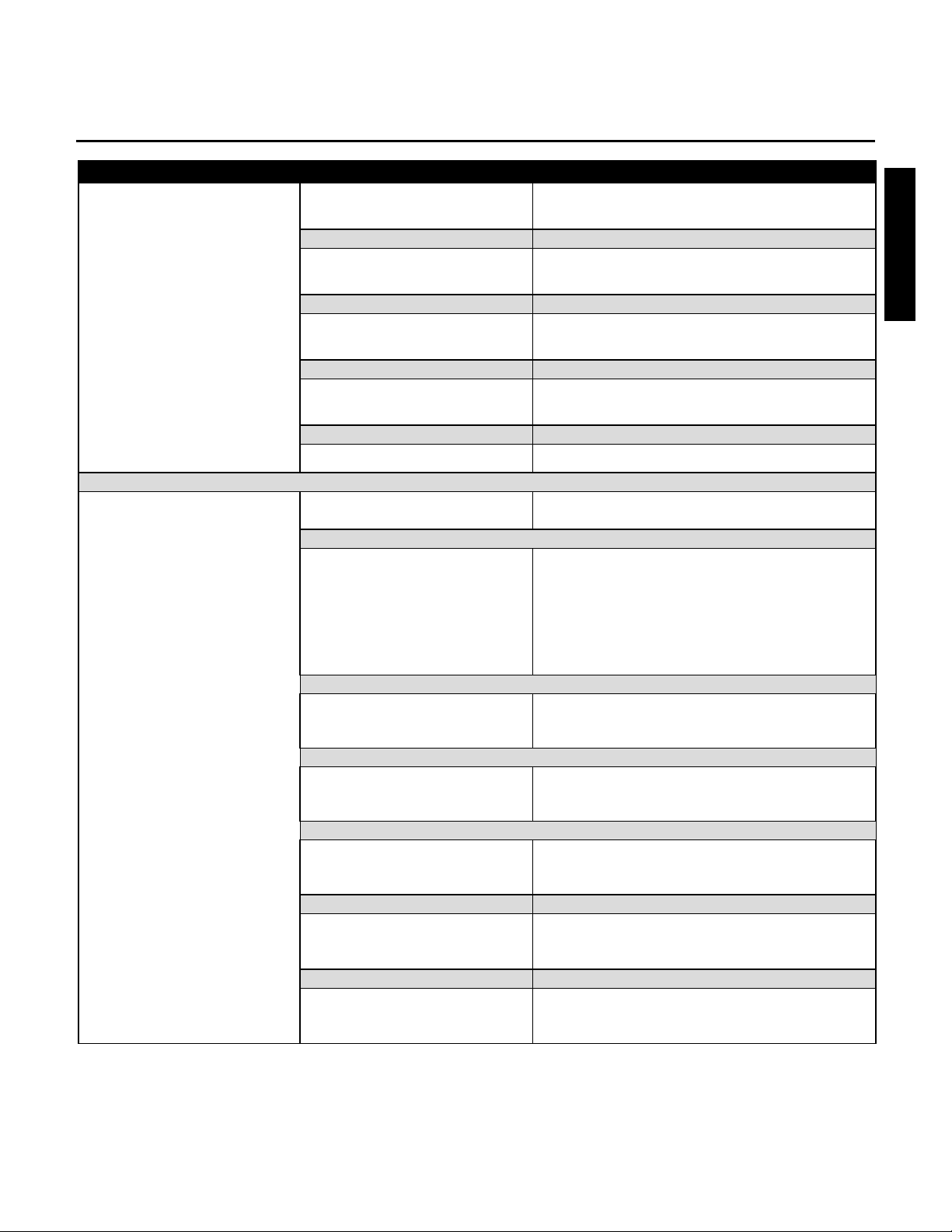
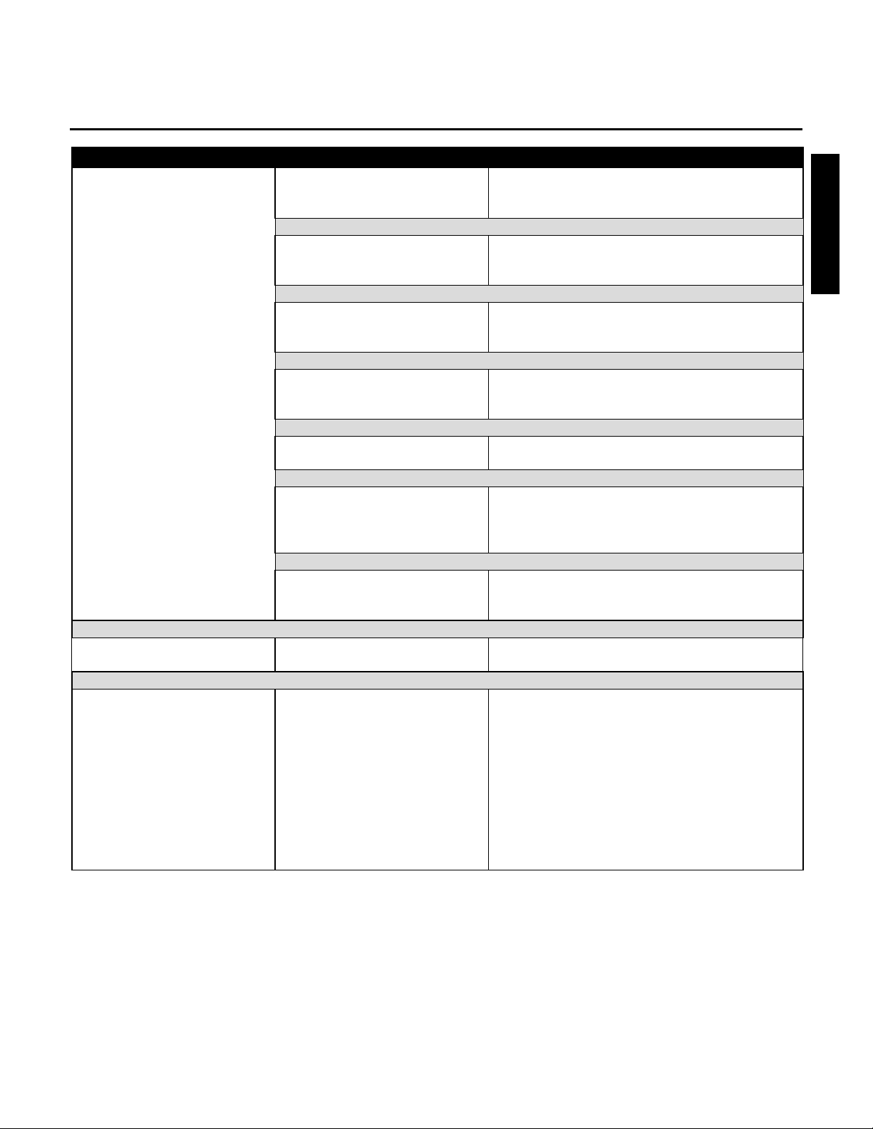
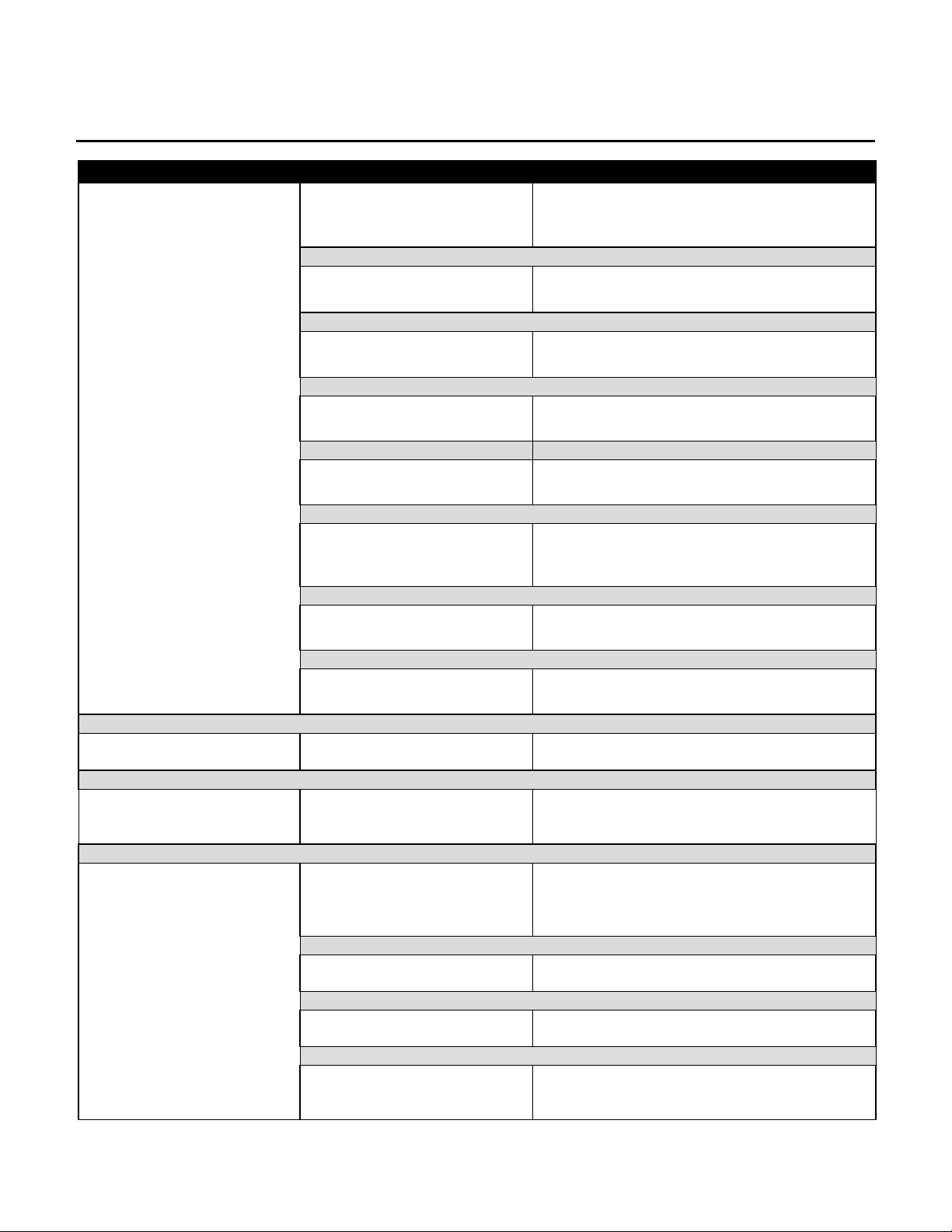
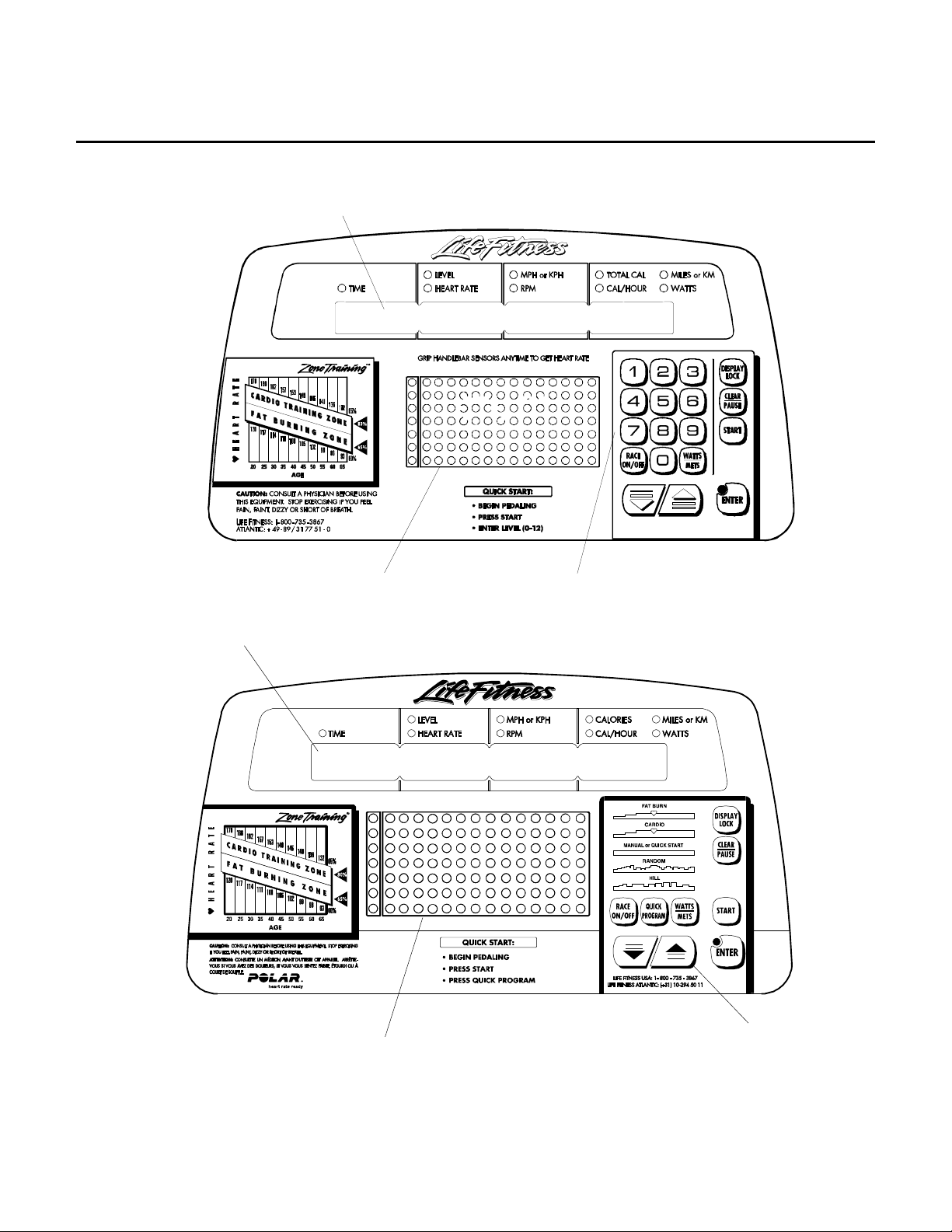
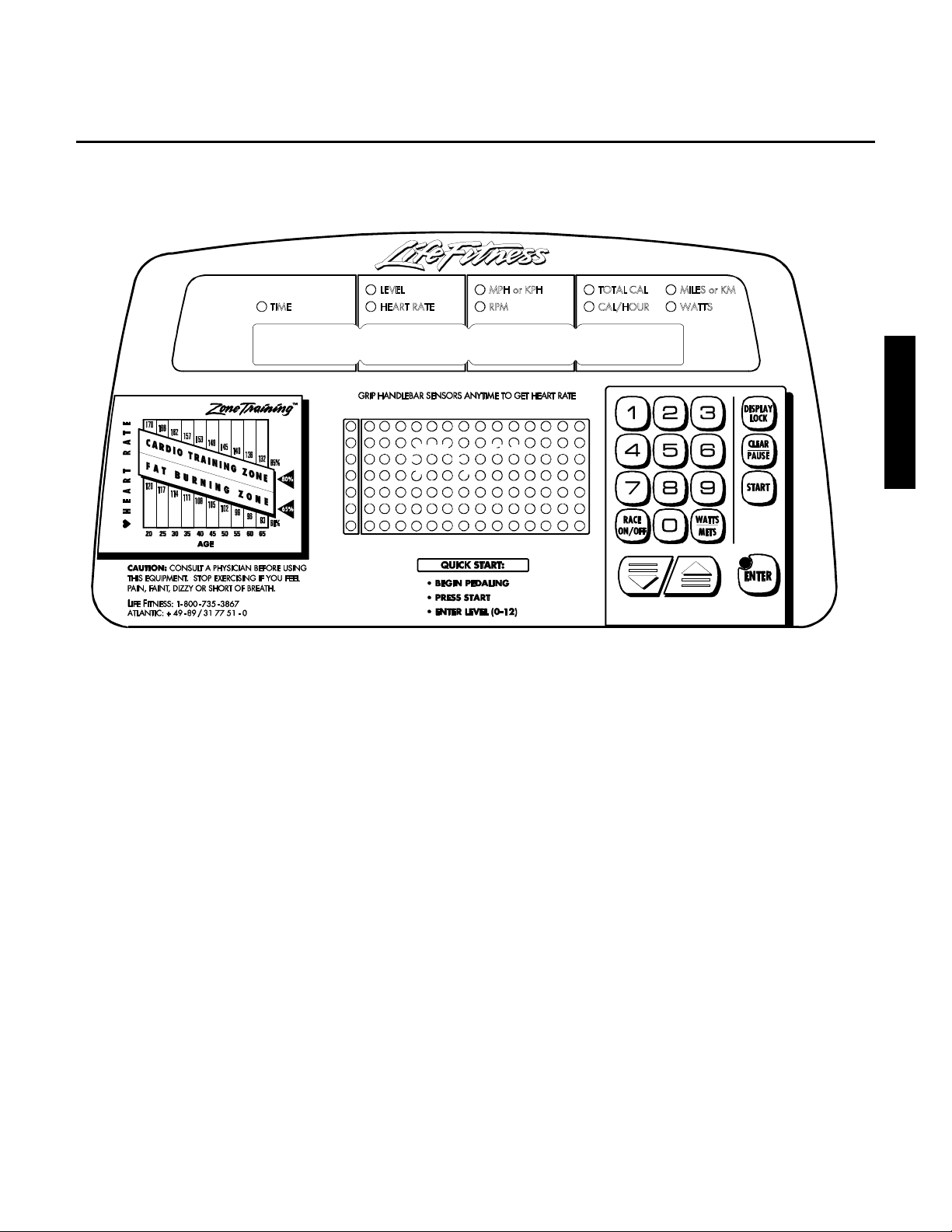
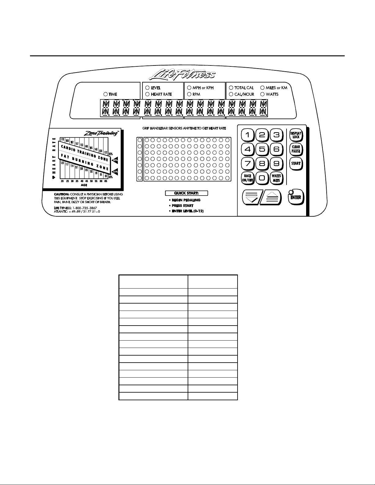
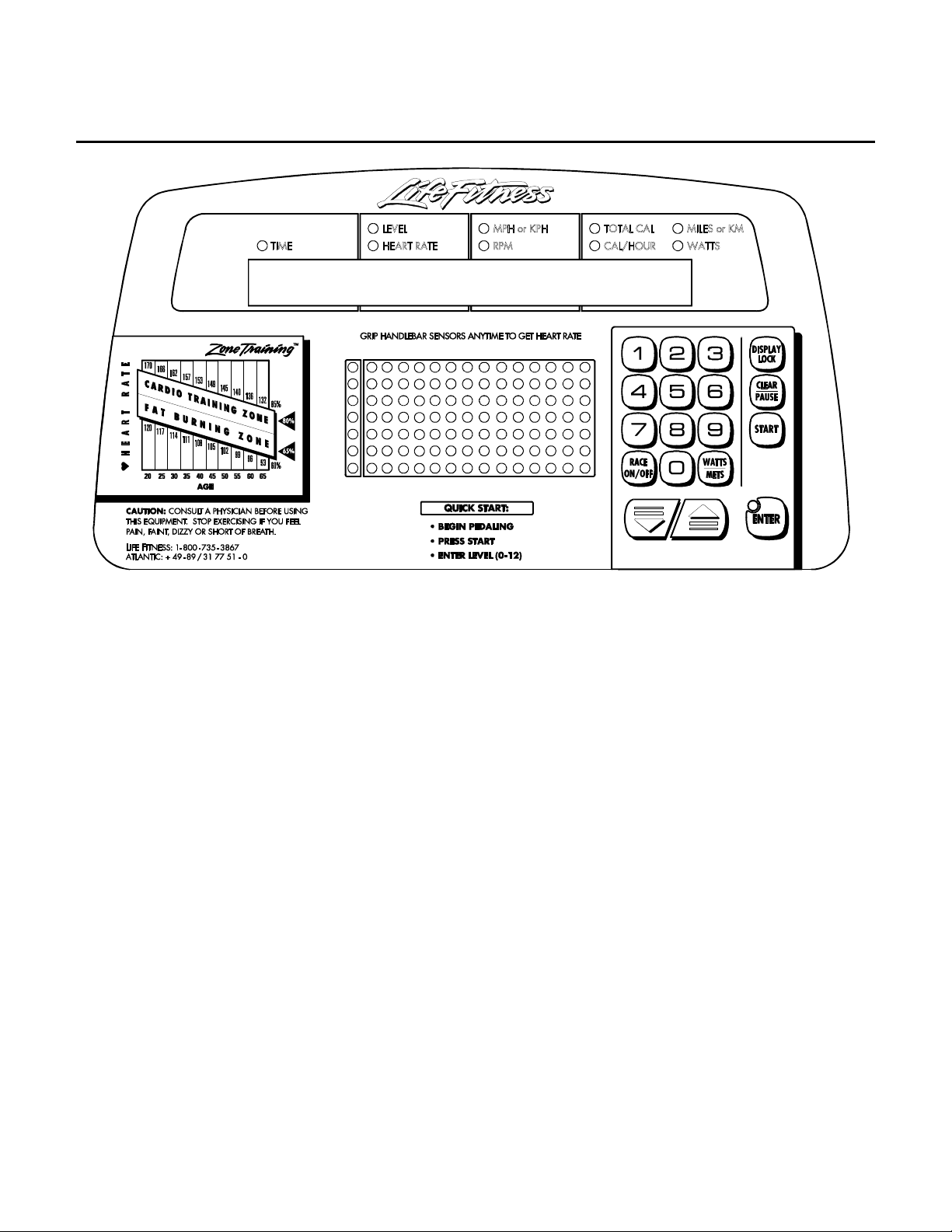
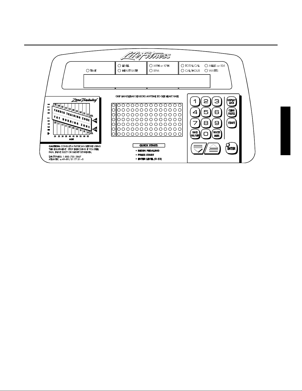
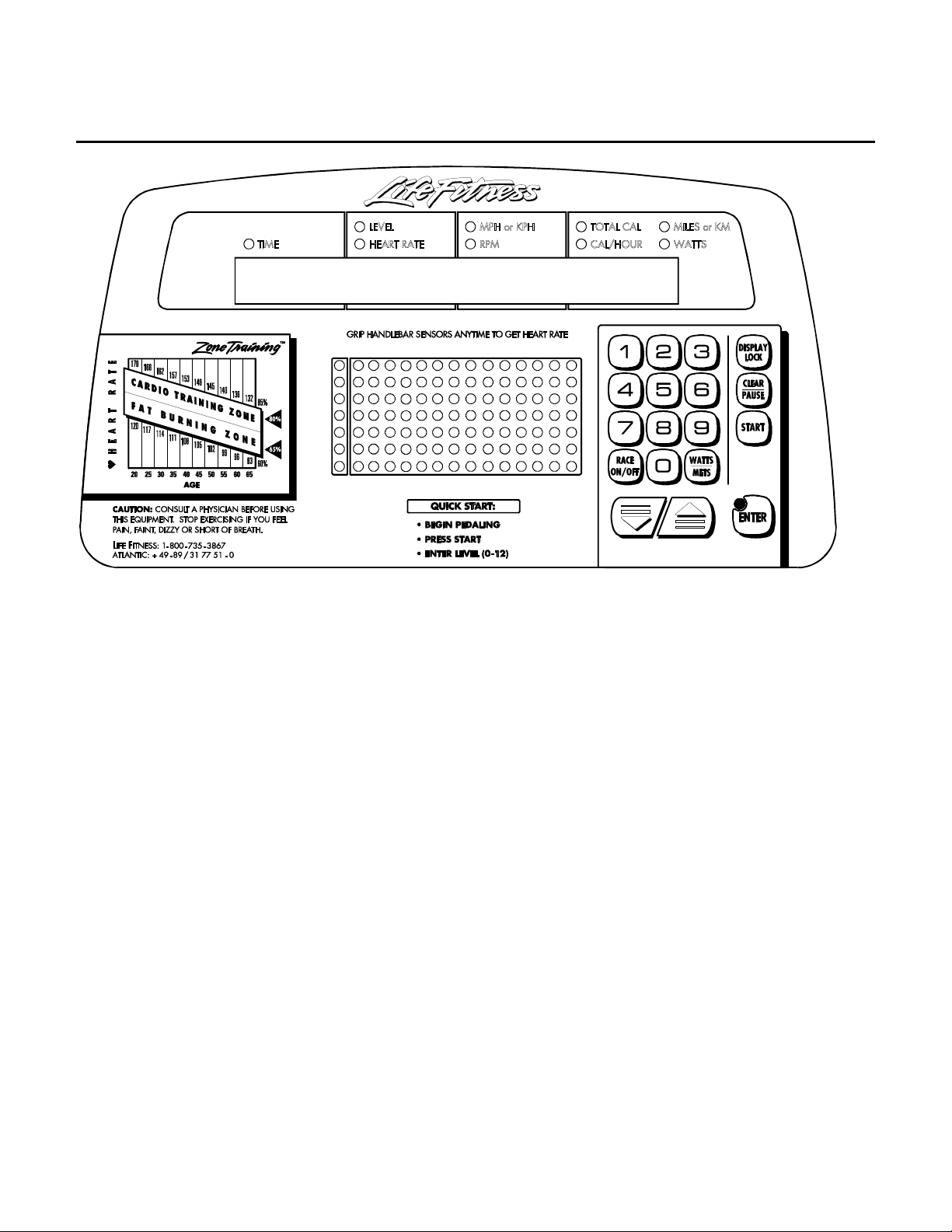
Display Console Layout
L950
C
Message Center
Message Center
Profile Window
Numeric Keypad
L 9100C
Profile Window
2
Arrow Keys
Lifecycle 9500 / 9100 Series Recumbent Exercise Bikes
HOW TO ENTER DIAGNOSTIC MODES
LC9500 While pedaling the bike over 45 RPMs, diagnostics can be entered by holding the 5
key or the down ARROW key and pressing the START key.
Section II
LC9100 While pedaling the bike over 45 RPMs, diagnostics can be entered by holding the
‘DOWN ARROW’ key and pressing the ‘START’ key.
3
Lifecycle 9500 / 9100 Series Recumbent Exercise Bikes
DIAGNOSTICS
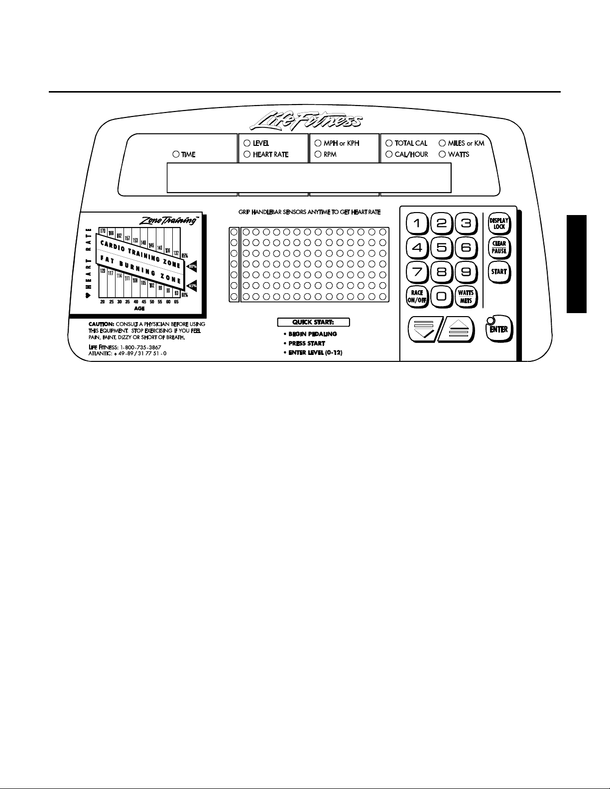
DIAGNOSTICS STATE 1 - ALL LEDS and KEYPAD TEST
Diagnostics is entered by holding the ‘DOWN ARROW’ key and depressing the ‘Start’ key while pedaling 45 RPM or
faster. On entry to this state, all of the LEDs will turn on.
Pressing keys will result in a beep sound and, for all but the START/ENTER’ and ‘CLEAR\PAUSE’ keys, a character
repeated across the message center display.
KEYS DISPLAYED
CHARACTER
0‘0’
1‘1’
2‘2’
3‘3’
4‘4’
5‘5’
6‘6’
7‘7’
8‘8’
9‘9’
DISPLAY LOCK ‘L’
RACE MODE ‘R’
WATTS/METS MODE ‘W’
UP ‘U’
DOWN ‘D’
Press the ‘CLEAR/PAUSE’ key to abort DIAGNOSTICS and return to the ‘PRESS START TO BEGIN’ state.
Press the ‘START/ENTER’ key to advance to DIAGNOSTICS STATE 2.
4
Lifecycle 9500 / 9100 Series Recumbent Exercise Bikes
DIAGNOSTICS
Section II
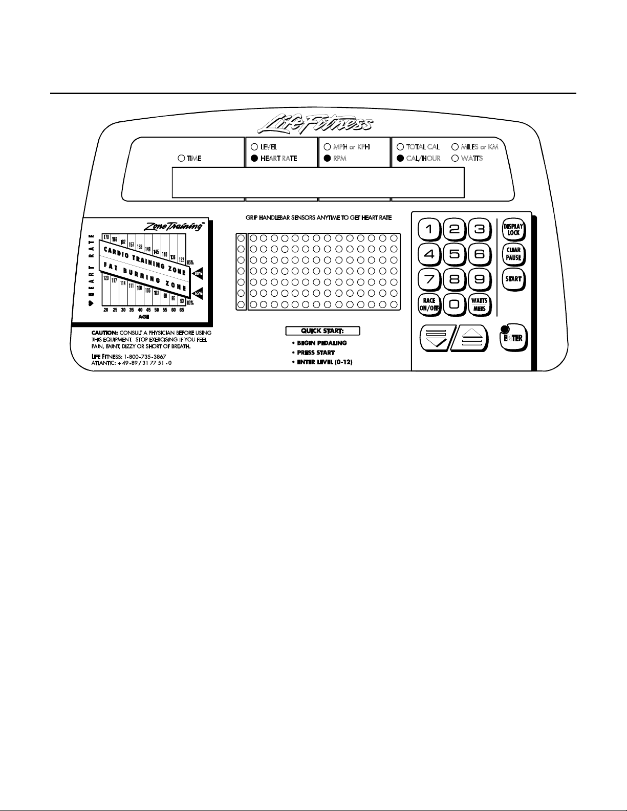
DIAGNOSTICS STATE 2: INDIVIDUAL LED TEST
On entry to this state, the individual LEDs and display segments will be tested.
Indicator LEDs, message center segments, and profile LEDs will all animate independently.
Press the ‘CLEAR/PAUSE’ key to return to DIAGNOSTICS STATE 1.
Press the ‘START/ENTER’ key to advance to DIAGNOSTICS STATE 3.
5
Lifecycle 9500 / 9100 Series Recumbent Exercise Bikes
DIAGNOSTICS
P1.31 HR 52 0
P1.31 HR 52 0
P1.31 HR 52 0P1.31 HR 52 0
DIAGNOSTICS STATE 3 - VERSION#: RPM, HR, and LOAD TESTS
The PROGRAM VERSION NUMBER (ex. P1.01) will be displayed in the ELAPSED TIME window.
The present RPM will be displayed in the RPM window.
The HEART RATE, if present, will be displayed in the LEVEL/HEART RATE window.
The present LOAD DUTY CYCLE applied to the alternator will be displayed in the CALORIES/HOUR window if the
LIFEPULSE GAIN display has not been selected. LOAD duty cycle ranges from 0-415 for 9V battery products, 0250 for all others in order of increasing load. This value can be adjusted using the UP/DOWN keys to decrement
and increment the LOAD duty cycle.
Pressing the DISPLAY LOCK key will disable the LOAD DUTY CYCLE display if enabled, turn off the
CALORIES/HR, and display the LIFEPULSE GAIN if HANDS ON LIFEPULSE sensors. Pressing the DISPLAY
LOCK key again will re-enable the LOAD DUTY CYCLE display.
Pressing the WATTS/METS key will toggle the display of the LIFEFITNESS PART # of the console software.
Press the ‘CLEAR/PAUSE’ key to return to DIAGNOSTICS STATE 2.
Press the ‘START/ENTER’ key to advance to DIAGNOSTICS STATE 4.
6

Lifecycle 9500 / 9100 Series Recumbent Exercise Bikes
DIAGNOSTICS
PX.XX 62 NONE 0
Section II
DIAGNOSTICS STATE 3 - VERSION#: RPM, NETWORK STATUS, AND LOAD TESTS
(Integrated PCB Only)
The PROGRAM VERSION NUMBER (ex. P1.01) will be displayed in the ELAPSED TIME window.
The present RPM will be displayed in the LEVEL and HEART RATE windows.
The NETWORK STATUS will be displayed in the RPM window.
The present LOAD DUTY CYCLE applied to the alternator will be displayed in the CALORIES/HOUR window. LOAD
DUTY CYCLE ranges from 0-415 for 9V battery products, 0-250 for all others in order of increasing load. This value
can be adjusted using the UP/DOWN arrow keys to increase or decrease the LOAD duty cycle. The LOAD DUTY
CYCLE can also be adjusted down or up in units of 25 using the 4 and 6 keys.
Pressing the WATTS/METS key will toggle the display of the Life Fitness part number of the console software.
Pressing the RACE key will toggle the tone ON or OFF.
Press the 'CLEAR/PAUSE' key to return to DIAGNOSTICS STATE 2.
Press the 'START/ENTER' key to advance to DIAGNOSTICS STATE 4.
7
Lifecycle 9500 / 9100 Series Recumbent Exercise Bikes
DIAGNOSTICS
P 1. 80 P3.90 OFF
DIAGNOSTICS STATE 4 - LIFEPULSE and NETWORK STATUS TESTS
The PROGRAM VERSION NUMBER of the HEART RATE DSP board ‘05 software (ex. P1.60, if present) will be
displayed in the ELAPSED TIME window.
The PROGRAM VERSION NUMBER of the HEART RATE DSP board DSP software (ex. P3.80, if present) will be
displayed in the HEART RATE window.
The status of the LIFELINK board and LIFE CENTER connection will be displayed in the CALORIES/HOUR
window. The following conditions will be reported.
‘NONE’ - No LIFELINK board detected.
‘NULL’ - Board detected but not communicating.
‘ON ‘ - ONLINE status with LIFE CENTER
‘OFF ‘ - OFFLINE status with LIFE CENTER.
Press the ‘CLEAR/PAUSE’ key to return to DIAGNOSTICS STATE 3.
Press the ‘START/ENTER’ key to advance to DIAGNOSTICS STATE 5.
8
Lifecycle 9500 / 9100 Series Recumbent Exercise Bikes
DIAGNOSTICS
HR C-0
L
DIAGNOSTICS STATE 4 - LIFEPULSE TESTS (Integrated PCB Only)
Upon entry to this diagnostic state, the LIFEPULSE software version number is displayed for 2 seconds. After this ,
the LP Comm Status is displayed for 2 seconds, which will either display 'LP PC COMM ON' or 'LP PC COMM
OFF'. Make sure 'LP PC COMM OFF' appears, or CSAFE will not function correctly. The LP Comm Status can be
toggled by pressing the 5 key during the 2 seconds when the LP Comm Status message is being displayed, and
does not normally need to be adjusted.
After these messages are done displaying, the LifePulse test information comes up.
G99
R
Section II
With both hands placed on the LifePulse sensors, the ELAPSED TIME begins counting in the TIME window. This
counter will stop counting as soon as a heart rate is displayed.
The GAIN is displayed in the RPM window.
The CONFIDENCE LEVEL between 0-9 is displayed in the CALORIES/HOUR window, with 0 indicating the lowest
confidence and 9 indicating the highest.
The profile window will display and 'L' when the left LifePulse sensor is being held. An 'R' when the right LifePulse
sensor is being held, and 'L' and 'R' when both sensors are being held.
Press the ‘CLEAR/PAUSE’ key to return to DIAGNOSTICS STATE 3.
Press the ‘START/ENTER’ key to advance to DIAGNOSTICS STATE 5.
9
Lifecycle 9500 / 9100 Series Recumbent Exercise Bikes
DIAGNOSTICS
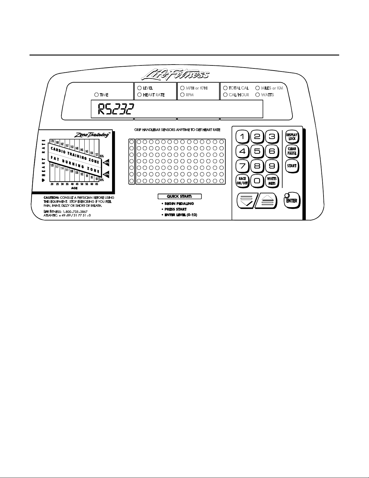
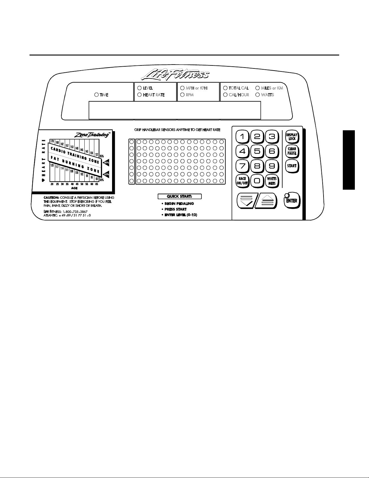
OFF
DIAGNOSTICS STATE 5 - LOOPBACK TEST
Within this state, the RS232 port is tested. A shorting jumper must be connected for the result of this test to be
correct.
If functioning correctly, “RS232 PASS” will be displayed.
If not-functioning correctly , “RS232 OFF” will be displayed.
Press the ‘CLEAR/PAUSE’ key to return to DIAGNOSTICS STATE 4.
Press the ‘START/ENTER’ key to advance to DIAGNOSTICS STATE 6.
10
Lifecycle 9500 / 9100 Series Recumbent Exercise Bikes
DIAGNOSTICS
CVA ENABLED
Section II
DIAGNOSTICS STATE 5 - CVA ENABLE/DISABLE (Integrated PCB Only)
Within this state, CVA support can be turned ON or OFF.
The "UP" and "DOWN" arrow keys toggle between CVA ENABLED and CVA DISABLED.
The ENTER key LED will indicated when the value is at the default setting of CVA DISABLED.
This value is stored in EEROM and is kept when the LifeCycle is not in use.
Press the ‘CLEAR/PAUSE’ key to return to DIAGNOSTICS STATE 4.
Press the ‘START/ENTER’ key to advance to DIAGNOSTICS STATE 6.
11
Lifecycle 9500 / 9100 Series Recumbent Exercise Bikes
DIAGNOSTICS
M A X D U R A T I O N 60
DIAGNOSTICS STATE 6 - MAXIMUM PROGRAM DURATION
Within this state, the MAXIMUM PROGRAM DURATION is displayed and can be adjusted from a range of 10-99
minutes.
The ‘DOWN ARROW’ will decrease the value by 1 minute. The key will Auto-Repeat if held.
The ‘UP ARROW’ will increase the value by 1 minute. The key will Auto-Repeat if held.
The ENTER key LED indicates when the value is at the default of 60 minutes. This value is stored in EEROM and is
kept when the unit is not in use.
To RESET the configuration items in the EEPROM to their default settings, hold the DISPLAY LOCK key down
while pressing the ENTER key.
Press the ‘CLEAR/PAUSE’ key to return to DIAGNOSTICS STATE 5.
Press the ‘START/ENTER’ key to advance to DIAGNOSTICS STATE 7.
12

Lifecycle 9500 / 9100 Series Recumbent Exercise Bikes
DIAGNOSTICS
T E L E M E T R Y O N
Section II
DIAGNOSTICS STATE 7 - TELEMETRY ENABLE/DISABLE
Within this state, the TELEMETRY can be turned ON or OFF. If a telemetry heart rate is detected, it will be
displayed when telemetry is set to ON. The Heart Rate LED will also be flashed every time a telemetry pulse is
received.
By default, the LifeCycles will have TELEMETRY ON.
The ‘DOWN ARROW’ will turn off the telemetry.
The ‘UP ARROW’ will turn on the telemetry and display a heart shape in the program profile window.
The ENTER key LED indicates when the value is at the default setting of TELEMETRY ON. This value is stored in
EEROM and is kept when the unit is not in use.
Press the ‘CLEAR/PAUSE’ key to return to DIAGNOSTICS STATE 6.
Press the ‘START/ENTER’ key to advance to DIAGNOSTICS STATE 8.
13

Lifecycle 9500 / 9100 Series Recumbent Exercise Bikes
DIAGNOSTICS
E N G L I S H U N I T S
DIAGNOSTICS STATE 8 - ENGLISH/METRIC UNITS
Within this state, ENGLISH or METRIC units can be selected.
The ‘DOWN ARROW’ will select METRIC units.
The ‘UP ARROW’ will select ENGLISH units.
The ENTER key LED indicates when the value is at the default setting of ENGLISH UNITS.
This value is stored in EEROM and is kept when the unit is not in use.
Press the ‘CLEAR/PAUSE’ key to return to DIAGNOSTICS STATE 7.
Press the ‘START/ENTER’ key to advance to DIAGNOSTICS STATE 9.
14

Lifecycle 9500 / 9100 Series Recumbent Exercise Bikes
R
DIAGNOSTICS
E C U M B E N T
Section II
DIAGNOSTICS STATE 9 - MODEL SELECTION
Within this state, configuration as an upright or a recumbent LifeCycle can be selected.
The ‘DOWN ARROW’ will configure as a Recumbent.
The ‘UP ARROW’ will configure as a Upright.
The ENTER key LED indicates when the value is at the default setting of UPRIGHT.
This value is stored in EEROM and is kept when the unit is not in use.
Press the ‘CLEAR/PAUSE’ key to return to DIAGNOSTICS STATE 8.
Press the ‘START/ENTER’ key to advance to DIAGNOSTICS STATE 10.
15

Lifecycle 9500 / 9100 Series Recumbent Exercise Bikes
DIAGNOSTICS
WATT P R O G R A M ON
DIAGNOSTICS STATE 10 - WATTS PROGRAM ENABLE/DISABLE
Within this state, WATTS can be turned ON or OFF.
By default, the LifeCycle will have the WATTS PROGRAM ON.
The ‘DOWN ARROW’ will turn OFF the WATTS PROGRAM.
The ‘UP ARROW’ will turn ON the WATTS PROGRAM.
The ENTER key LED indicates when the value is at the default setting of WATTS PROGRAM ON.
The value is stored in EEROM and is kept when the bike is not in use.
Press the ‘CLEAR/PAUSE’ key to return to DIAGNOSTICS STATE 9.
Press the ‘START/ENTER’ key to advance to DIAGNOSTICS STATE 11.
16

Lifecycle 9500 / 9100 Series Recumbent Exercise Bikes
DIAGNOSTICS
METS P R O G R A M ON
Section II
DIAGNOSTICS STATE 11 - METS PROGRAM ENABLE/DISABLE
Within this state, METS PROGRAM can be turned ON or OFF.
By default, the LifeCycle will have the METS PROGRAM ON.
The ‘DOWN ARROW’ will turn OFF the WATTS PROGRAM.
The ‘UP ARROW’ will turn ON the WATTS PROGRAM.
The ENTER key LED indicates when the value is at the default of METS PROGRAM ON.
This value is stored in EEROM and is kept when the bike is not in use.
Press the ‘CLEAR/PAUSE’ key to return to DIAGNOSTICS STATE 10.
Press the ‘START/ENTER’ key to advance to DIAGNOSTICS STATE 12.
17

Lifecycle 9500 / 9100 Series Recumbent Exercise Bikes
DIAGNOSTICS
6 V B A T T E R Y
DIAGNOSTICS STATE 12 - POWER SUPPLY CONFIGURATION
Within this state, the power supply selection can be made.
The arrow keys will scroll through the selections of '6 VOLT BATTERY', 'EXTERNAL SUPPLY', or '9 VOLT
BATTERY'.
NOTE: LC9100 uses a 9 volt battery. LC9500 uses a 6 volt battery.
The ENTER key LED indicates when the value is the default of 6V battery.
This value is stored in EEROM and is kept when the unit is not in use.
Press the ‘CLEAR/PAUSE’ key to return to DIAGNOSTICS STATE 11.
Press the ‘START/ENTER’ key to advance to DIAGNOSTICS STATE 13.
18

Lifecycle 9500 / 9100 Series Recumbent Exercise Bikes
DIAGNOSTICS
H O U R S =
12
DIAGNOSTICS STATE 13 - TOTAL HOURS and STATISTICS
Upon entry to this state, TOTAL HOURS are displayed.
STATISTICS can be displayed using the UP and DOWN arrow keys.
The ‘UP ARROW’ allows scrolling through the available programs and shows the number of times each program
has been selected. The ‘DOWN ARROW’ backs up through the list of available programs and back to the total
hours displayed.
Section II
To clear the statistics in the EEPROM, hold the DISPLAY LOCK key down while pressing the ENTER key.
The Programs are:
HOUR
HILL
RANDOM
MANUAL
FAT
CARDIO
FIT
WATTS
METS
QUICK
HRT HILL
HRT INT
HRT EXT
SPRT TRN
Pressing the ‘CLEAR/PAUSE’ key will return to DIAGNOSTICS STATE 12.
Pressing the ‘START/ENTER’ key will advance to DIAGNOSTICS STATE 14.
19

Lifecycle 9500 / 9100 Series Recumbent Exercise Bikes
DIAGNOSTICS
N U M E R I C
DIAGNOSTICS STATE 14- NUMERIC KEYS CONFIGURATION
Within this state, the unit can be configured as to the presence of numeric keys.
The ‘DOWN ARROW’ will display “NUMERICS OFF”.
The ‘UP ARROW’ will display “NUMERICS ON”.
K E Y S
ON
The ENTER key LED indicates when the value is at the default of NUMERIC KEYS ON.
This value is stored in EEROM and is kept when the unit is not in use.
Press the ‘CLEAR/PAUSE’ key to return to DIAGNOSTICS STATE 13.
Press the ‘START/ENTER’ key to advance to DIAGNOSTICS STATE 15.
20

Lifecycle 9500 / 9100 Series Recumbent Exercise Bikes
2
DIAGNOSTICS
8:45 135
DIAGNOSTICS STATE 15 PHOTO SHOOT
This state is solely intended to be used for PHOTO SHOOTS.
None of the data items displayed are real.
Press the ‘CLEAR/PAUSE’ key to return to DIAGNOSTICS STATE 14.
Press the ‘START/ENTER’ key to advance to DIAGNOSTICS STATE 16.
82
725
Section II
21

Lifecycle 9500 / 9100 Series Recumbent Exercise Bikes
DIAGNOSTICS
DIAGNOSTICS STATE 15 PROGRAMS ENABLE/DISABLE (Integrated PCB Only)
Enable or disable HEART RATE HILL, HEART RATE INTERVAL, HEART RATE EXTREME, or REAL WORLD
BIKE.
The DOWN ARROW will display PROGRAMS OFF.
The UP ARROW will display PROGRAMS ON.
The ENTER key LED indicates when the value is set to default of PROGRAMS OFF.
This value is stored in EEROM and is kept when the unit is not in use.
Press the ‘CLEAR/PAUSE’ key to return to DIAGNOSTICS STATE 14.
Press the ‘START/ENTER’ key to advance to DIAGNOSTICS STATE 16.
22

Lifecycle 9500 / 9100 Series Recumbent Exercise Bikes
DIAGNOSTICS
Section II
DIAGNOSTICS STATE 16 LANGUAGE SELECTION (ntegrated PCB Only)
Within this state, the LANGUAGE can be changed to nay one of 7 languages, including English, German, French,
Italian, Dutch, Spanish or Portuguese.
The UP ARROW will display the next language in the list.
The DOWN ARROW will display the previous language in the list.
The ENTER key LED indicates when the language is set to the default of ENGLISH.
This value is stored in EEROM and is kept when the unit is not in use.
Press the ‘CLEAR/PAUSE’ key to return to DIAGNOSTICS STATE 15.
Press the ‘START/ENTER’ key to advance to DIAGNOSTICS STATE 17.
23

Lifecycle 9500 / 9100 Series Recumbent Exercise Bikes
DIAGNOSTICS
DIAGNOSTICS STATE 17 EEPROM TEST (Integrated PCB Only)
Within this state, EEPROM can be tested.
This diagnostic state tests the Display Console EEPROM by reading, writing, and replacing all used locations in the
Display Console EEPROM. The EEPROM location being tested will appear in the display message center. Pressing
the DOWN ARROW will initiate the EEPROM test. If the test completes successfully, the message EEPROM
GOOD will appear. If the test fails, the message EEPROM BAD AT XX will display with the bad EEPROM location.
Press the ‘CLEAR/PAUSE’ key to return to DIAGNOSTICS STATE 16.
Press the ‘START/ENTER’ key to advance to DIAGNOSTICS STATE 18.
24

Lifecycle 9500 / 9100 Series Recumbent Exercise Bikes
2
DIAGNOSTICS
8:45 135
DIAGNOSTICS STATE 18 PHOTO SHOOT (Integrated PCB Only)
This state is solely intended to be used for PHOTO SHOOTS.
None of the data items displayed are real.
Press the ‘CLEAR/PAUSE’ key to return to DIAGNOSTICS STATE 17.
82
725
Section II
25

Lifecycle 9500 / 9100 Series Recumbent Exercise Bikes
NOTES:
26

Lifecycle 9500HR / 9100 Series Recumbent Exercise Bikes
SECTION III
How To...
SERVICE AND REPAIR GUIDES
Section III
1

Lifecycle 9500HR / 9100 Series Recumbent Exercise Bikes
y
.
w
.
How To...REPLACE THE ALTERNATOR
Tools Required: Combination wrenches, belt tension gage, and Phillips screwdriver
1. See “How To…Replace Shrouds” in this
section.
2. Disconnect all terminal wires noting their colors
and tagging their locations.
3. Mark the ALTERNATOR position at the
TENSIONING BOLT BRACKET, then remove
the TENSIONING BOLT.
4. Remove the PIVOT BOLT and hardware from
the ALTERNATOR.
5. Remove the ALTERNATOR from the unit.
NOTICE: If only the alternator is being replaced,
then remove the ALTERNATOR PULLEY.
6. Install the new alternator in the reverse order.
Make sure that the ALTERNATOR BELT is
properly aligned to the LARGE PULLEY as
shown otherwise damage to the belt can occur.
Alternator Tensioning Bolt
Orange
Torque
25-30 IN. LBS.
Pivot Bolt
Yello
Red
Torque
25-30 IN. LBS
Black
Black/White
7. Locate the alternator at the marked area on the
alternator bracket. Alternator belt tension should
be from 60-70 lbs.
Alternator Belt
Large Pulley
Alternator Pulle
Alternator Belt
Alternator
Mounting
Bracket
Tensioning Bolt
Torque 18-20 FT. LBS
Alternator
Assembly
Nut/Washer
Pivot Bolt
Torque 30-35 FT. LBS.
2

Lifecycle 9500HR / 9100 Series Recumbent Exercise Bikes
How To...REPLACE THE ALTERNATOR BELT
Tools Required: Combination wrenches, pliers, screwdrivers, e-ring tool, center punch, and belt tensioning gage
1. See “How To…Replace Shrouds” in this
section.
2. Mark the position of the ALTERNATOR
TENSIONING BOLT at the MOUNTING
BRACKET, then remove TENSIONING
BOLT.
3. Loosen the ALTERNATOR PIVOT BOLT
and push the ALTERNATOR forward to
slacken the ALTERNATOR BELT.
4. Mark the position of the IDLER BRACKET,
Remove and loosen MOUNTING BOLTS
as illustrated.
5. Loosen the TENSION BOLT and move the
IDLER BRACKET forward to slacken the
POWER GRIP BELT.
Alternator
Mounting
Bracket
Idler Bracket
Tensioning Bolt
Torque 5-7 FT. LBS.
Mounting Bolt (Loosen)
Torque 27-33 IN. LBS.
Mounting Bolt (Remove)
Torque 27-33 IN. LBS.
Alternator
Tensioning Bolt
Torque 18-20 FT. LBS.
Alternator Pivot Bolt
Torque 30-35 FT. LBS.
Alternator Belt
Section III
Powe r Grip Belt
3

Lifecycle 9500HR / 9100 Series Recumbent Exercise Bikes
y
How To...REPLACE THE ALTERNATOR BELT (Continued)
6. Remove the RETAINER BOLT and
RETAINER from the end of the
PULLEY shaft.
7. Remove the left E-RING from the left
side of the PULLEY first, then remove
the right E-RING.
8. From the belt side, tap out the SHAFT
from the unit.
9. Remove the ALTERNATOR BELT.
Pulley Shaft
Retainer Bolt
E-Ring
10. Install the new alternator in the reverse order. Make sure
that the ALTERNATOR BELT is properly aligned to the
LARGE PULLEY as shown otherwise damage to the belt
can occur.
11. Locate the alternator at the marked area on the alternator
bracket. Alternator belt tension should be from 60-70 lbs.
and the POWER GRIP BELT from 35-55 lbs.
Washer
Freewheel
Large Pulley
Washer
Washer
Pulley
Alternator Belt
Alternator Pulle
Retainer
E-Ring
4

Lifecycle 9500HR / 9100 Series Recumbent Exercise Bikes
How To...REPLACE THE FREEWHEEL/PULLEY ASSEMBLY
Tools Required: Combination wrenches, pliers, screwdrivers, e-ring tool, center punch, and belt tensioning gage
1. See “How To…Replace Shrouds” in
this section.
2. Mark the position of the
ALTERNATOR TENSIONING BOLT
at the MOUNTING BRACKET, then
remove TENSIONING BOLT.
3. Loosen the ALTERNATOR PIVOT
BOLT and push the ALTERNATOR
forward to slacken the
ALTERNATOR BELT.
4. Mark the position of the IDLER
BRACKET, Remove and loosen
MOUNTING BOLTS as illustrated.
5. Loosen the TENSION BOLT and
move the IDLER BRACKET forward
to slacken the POWER GRIP BELT.
Idler Bracket
Tensioning Bolt
Torque 5-7 FT. LBS.
Mounting Bolt (Loosen)
Torque 27-33 IN. LBS.
Mounting Bolt (Remove)
Torque 27-33 IN. LBS.
Alternator
Mounting
Bracket
Alternator
Tensioning Bolt
Torque 18-20 FT. LBS.
Section III
Alternator Belt
Alternator Pivot Bolt
Torque 30-35 FT. LBS.
Power Gri p Belt
5

Lifecycle 9500HR / 9100 Series Recumbent Exercise Bikes
y
How To...REPLACE THE FREEWHEEL/PULLEY ASSEMBLY (Continued)
6. Remove the RETAINER BOLT and
RETAINER from the end of the SHAFT.
7. Remove the left E-RING from the left
side of the PULLEY first, then remove
the right E-RING.
8. From the belt side, tap out the SHAFT
from the unit.
9. Pull the FREEWHEEL/PULLEY
ASSEMBLY forward and out of the
10. Slide the FREEWHEEL off the SHAFT
noting location of washers.
bike.
Pulley Shaft
Retainer Bolt
E-Ring
11. Install the new alternator in the reverse order. Make sure
that the ALTERNATOR BELT is properly aligned to the
LARGE PULLEY as shown otherwise damage to the belt
can occur.
12. Locate the alternator at the marked area on the alternator
bracket. Alternator belt tension should be from 60-70 lbs.
and the POWER GRIP BELT from 35-55 lbs.
Washer
Freewheel
Large Pulley
Washer
Washer
Pulley
Alternator Belt
Alternator Pulle
Retainer
E-Ring
6

Lifecycle 9500HR / 9100 Series Recumbent Exercise Bikes
How To...REPLACE THE POWER GRIP BELT
Tools Required: Combination wrenches, pliers, screwdrivers, e-ring tool, center punch, and belt tensioning gage
1. See “How To…Replace Shrouds” in this
section.
2. Mark the position of the ALTERNATOR
TENSIONING BOLT at the MOUNTING
BRACKET, then remove TENSIONING
BOLT.
Idler Bracket
Tensioning Bolt
Torque 5-7 FT. LBS.
3. Loosen the ALTERNATOR PIVOT BOLT
and push the ALTERNATOR forward to
slacken the ALTERNATOR BELT.
4. Mark the position of the IDLER
BRACKET, Remove and loosen
MOUNTING BOLTS as illustrated.
5. Loosen the TENSION BOLT and move
the IDLER BRACKET forward to slacken
the POWER GRIP BELT.
Alternator
Mounting
Bracket
Alternator
Tensioning Bolt
Torque 18-20 FT. LBS.
Mounting Bolt (Loosen)
Torque 27-33 IN. LBS.
Mounting Bolt (Remove)
Torque 27-33 IN. LBS.
Alternator Pivot Bolt
Torque 30-35 FT. LBS.
Section III
Alternator Belt
Power Grip Belt
7

Lifecycle 9500HR / 9100 Series Recumbent Exercise Bikes
A
y
How To...REPLACE THE POWER GRIP BELT (Continued)
6. Remove the RETAINER BOLT and
RETAINER from the end of the
SHAFT.
7. Remove the left E-RING from the left
side of the PULLEY first, then remove
the right E-RING.
8. From the belt side, tap out the SHAFT
from the unit.
9. Pull the FREEWHEEL/PULLEY
ASSEMBLY forward and out of the bike
and remove the POWER GRIP BELT.
Pulley Shaft
Retainer Bolt
E-Ring
10. Install the new alternator in the reverse order. Make
sure that the ALTERNATOR BELT is properly aligned
to the LARGE PULLEY as shown otherwise damage to
the belt can occur.
11. Locate the alternator at the marked area on the
alternator bracket. Alternator belt tension should be
from 60-70 lbs. and the POW ER GRIP BELT from 3555 lbs.
Washer
Washer
Freewheel
Alternator Belt
Large Pulley
Pulley
Washer
E-Ring
Retainer
lternator Pulle
8

Lifecycle 9500HR / 9100 Series Recumbent Exercise Bikes
How To...REPLACE THE SEAT LOCKING MECHANISM ASSEMBLY
Tools Required: 5/32 inch hex key wrench
1. Disengage the LOCKING
MECHANISM and slide the seat
to its most forward position.
2. Remove the two 5/32 inch hex
key screws from the LOCKING
MECHANISM.
3. Remove the LOCKING
MECHANISM.
4. Install new LOCKING
MECHANISM in reverse order.
Locking
Mechanism
Bolts
Section III
9

Lifecycle 9500HR / 9100 Series Recumbent Exercise Bikes
g
How To... REPLACE THE CRANK ARM BEARINGS
Tools Required: Special crank arm wrench required (available from Life Fitness), FT LBS. torque wrench, standard
screwdriver, hex key set, and clean rag.
Bearing Retaining Screw
1. See “How To…Replace Shrouds” in
this section.
Bearing Retaining Screw
2. Loosen the POWER GRIP BELT. See
“How To…Replace Power Grip Belt.”
3. Remove the left BEARING RETAINER
SCREWS (2).
4. In a clockwise rotation, remove the
LEFT CRANK NUT bearing Assembly.
5. Unbend the tabs of the TAB
WASHER. Remove and discard.
6. In a clockwise rotation, remove the
LEFT BEARING NUT from the
CRANK ARM.
7. Through the ACCESS HOLE in the
crank arm PULLEY, remove the right
BEARING RETAINER SCREWS (2).
8. Remove the CRANKARM out of the bike frame from its right side.
9. Remove the right crank arm BEARING NUT and slide it off the CRANKARM.
10. Install new crankarm bearings in reverse order. Before assembling, use a clean rag to thoroughly clean out the
crank arm bearing area.
Left Crank Arm
Left Crank Nut
Tab Washer
Left Bearing Nut
Bearing Retaining Screw
Left Bearing
Access Hole
Right Bearing Nut
Right Bearing
Bearing Retainin
Screw
Right Crank Arm
11. Install the RIGHT BEARING NUT assembly onto the right CRANKARM and hand thread (clockwise). Finalize
tightening to a torque value between 20-30 ft lbs.
12. Install the CRANK ARM through the right side of the frame seating the right crank bearing in place.
10

Lifecycle 9500HR / 9100 Series Recumbent Exercise Bikes
How To... REPLACE THE CRANK ARM BEARINGS (Cont.)
13. Install the LEFT BEARING NUT assembly over the left CRANKARM, and hand-thread (counterclockwise).
Using torque wrench, initially tighten 9-12 FT. LBS. seating torque, then back off the bearing nut and re-torque
to 4 FT. LBS.
14. Install a new TAB WASHER on the left crank arm. Make sure that the inner tab aligns with the groove in the
crank arm, and that the outer pre-bent tab is positioned against the center of the bearing nut flat. If it is not,
slightly back off the bearing nut (clockwise) until this tab is positioned in the center of the bearing nut flat, then
secure it against the bearing nut flat with a hammer.
CLOCKWISE ROTATION
Left Bearing Nut
Pre-Bent Tab
at center flat
Left Bearing
Frame
Inner Tab
Straight Tab
at center flat
INCORRECT
TAB POSITION
15. Install the CRANK ARM NUT and hand-thread (counterclockwise) against the TAB WASHER. With the special
wrench, tighten to a torque of 4 FT. LBS. Now bend the remaining tab up against the center flat of the crank
arm nut. If necessary, back off this nut (clockwise) until the tab is positioned in the center of the bearing nut flat
before securing.
16. Install the BEARING RETAINER SCREWS (4).
17. Re-install the DRIVE BELTS, SHROUDS, and PEDALS.
CORRECT
TAB POSITION
(align with
groove in
crank arm)
Section III
11

Lifecycle 9500HR / 9100 Series Recumbent Exercise Bikes
How To... REPLACE THE SEAT ASSEMBLY and EXTRUSION
Tools Required: 1/2 inch wrench, Standard screwdriver, and 5/32 inch Hex key wrench
1. See “How To…Replace Shrouds” in this section.
2.
Remove the SEAT STOP in front of the seat support
by removing two screws from the top and front of the
seat assembly.
3. From under the EXTRUSION, disconnect the FLAT
FLEX CABLE 4-Pin Connector from the Main Cable,
unhook the FLAT FLEX CABLE from the clip, remove
two torx screws holding the retainer bracket for the
FLAT FLEX CABLE, and remove the grommet.
4. Disengage the LOCKING MECHANISM and carefully
back the SEAT ASSEMBLY off the EXTRUSION
while guiding the flat flex cable out from the seat
extrusion.
Top Screw
5. If necessary to replace the EXTRUSION, remove the
FLAT FLEX CABLE in the EXTRUSION, then
remove four mounting bolts located under the ends
of the EXTRUSION. Replace EXTRUSION and
torque four MOUNTING BOLTS 200-220 IN. LBS.
6. Install the new SEAT ASSEMBLY in the reverse
order and adjust SEAT ROLLERS. “See “How
To…Adjust Seat Roller Adjustment” in this section.
Front Screw
Seat Stop
Seat Locking
Mechanism
Extrusion
12
Mounting Bolts
(4 places)
Torque 200-220 IN.LBS.
Flat Flex Cable

Lifecycle 9500HR / 9100 Series Recumbent Exercise Bikes
How To...REPLACE THE MAIN WIRE HARNESS
Tools Required: 1/4, 5/16, and 3/8 inch wrenches, side cutters, and standard screwdriver
1. Refer to “How To…Replace Display
Console and Handle Bar” in this section to
remove the HANDLEBAR ASSEMBLY
and disconnect the MAIN WIRE
HARNESS connectors.
2. Refer to “How To…Replace Shrouds” in
this section to remove the right SHROUD.
3. For the LC9500HR only, disconnect the
BLACK (neg) wire from the (-) post on the
BATTERY, then the RED (pos) wire from
the (+) post.
4. Disconnect the MAIN WIRE HARNESS
(P1) at the ALTERNATOR CONTROL
BOARD.
5. Note the location of the CABLE TIES on
frame, then cut them off.
6. Route the MAIN WIRE HARNESS out
through the bottom FRAME TUBE and
secure with new cable ties.
7. Install the new MAIN WIRE HARNESS in the reverse order of the above steps.
Frame Tube
Main Wire Harness
(in handle bar)
Main Wire Harness
(in frame tube)
Tie
Strap
Section III
13

Lifecycle 9500HR / 9100 Series Recumbent Exercise Bikes
How To...ADJUST SEAT ROLLER ADJUSTMENT
Tools Required: Two torque wrenches, combination wrench set
1. The SEAT ROLLERS are adjusted to a specified
resistance load. If the seat moves too freely with
excessive side-to-side movement, then the seat
rollers must be adjusted as follows.
2. Using a ½ inch wrench, loosen all four(4) SEAT
ROLLER CLAMP NUTS, then retighten by hand.
3. Make initial adjustments to the SEAT ROLLERS on the
right side of the unit first. This is done to ensure that
the two right guide rollers are properly seated in the Vchannel of the seat extrusion. Once the SEAT
ROLLERS on the right side are adjusted, then proceed
to adjust the seat rollers on the left side of the unit.
Right Side
NOTE: Step 4 requires use of two inch pound torque
wrenches. One to maintain a resistance load against the
TAKE-UP ROLLER and the other to torque the ROLLER
CLAMP NUT.
4. Starting with the right side SEAT ROLLERS, adjust the
first TAKE-UP ROLLER NUT to 60-65 in. lbs. in a
clockwise direction. Observe that the ROLLER CLAMP
NUT will move up. This indicates that the seat roller is
being forced up against the extrusion. Continue to
maintain the 60-65 in. lbs. resistance load on the takeup roller, and secure the seat roller position by
tightening the ROLLER CLAMP NUT from 100-120 in.
lbs. Repeat this procedure for other remaining right
roller. Once the right side is adjusted, repeat this
procedure for the left side. Always set the right side
seat rollers first. Failure to do so, will result in side-toside seat movement.
5. With all SEAT ROLLERS adjusted, test operation of the
seat assembly for a 15-25 lbs. pulling force and to
insure that no side-to-side movement exists. Repeat
this procedure as required.
Seat Roller
Clamp Nut
Take-Up
Roller Nut
Right SideLeft Side
Seat Roller
Clamp Nut
Seat Locking
Mechanism
Guide Roller
V-Channel
(right side
of seat extrusion)
Take-Up
Roller Nut
14

Lifecycle 9500HR / 9100 Series Recumbent Exercise Bikes
How To... REPLACE THE BATTERY(LC9500HR)
Tools Required: Standard screwdriver
1. Tilt the bike on its side.
2. Disconnect the BLACK (neg) wire from the (-)
post on the BATTERY then the RED (pos) wire
from the (+) post.
Battery
3. Remove the two SCREWS securing the
BATTERY to the bracket. Remove the
BATTERY and discard.
4. Install new BATTERY and secure with the two
SCREWS.
5. Reconnect the BLACK (neg) wire to the (-) post
on the BATTERY, and the RED (pos) wire to
the (+) post. Carefully tuck the BATTERY
WIRES back into the HOUSING.
6. Lift the bike to its upright position, and test all
operations.
Bracket
6V battery
Screws
32-35 IN. LBS.
Section III
15

Lifecycle 9500HR / 9100 Series Recumbent Exercise Bikes
How To... REPLACE THE BATTERY(LC9100)
Tools Required: Phillips screwdriver
1. Locate and remove the SCREW from the
BATTERY DOOR located on the rear of
the CONSOLE.
2. Disconnect the 9 VOLT ALKALINE
BATTERY from the WIRE HARNESS and
replace with a new 9 VOLT ALKALINE
BATTERY.
3. Carefully insert 9 VOLT ALKALINE
BATTERY and WIRE HARNESS into the
back of the display console.
4. Reinstall the BATTERY DOOR and
secure with SCREW.
Console
9 Volt Alkaline Battery
Screw
Wire Harness
Battery Door
16

Lifecycle 9500HR / 9100 Series Recumbent Exercise Bikes
How To... REPLACE THE CONSOLE AND HANDLEBAR ASSEMBLY
Tools Required: Phillips screwdriver and Allen wrench set
1. Remove four PHILLIPS SCREWS from
the SUPPORT BRACKET.
2. Lift the DISPLAY CONSOLE off the
support bracket to view wiring cables,
then disconnect the MAIN CABLE,
LIFEPULSE CABLE (LC9500HR), and
TELEMETRY CABLE from the back of
the DISPLAY CONSOLE.
3. Remove two HEX SCREWS from the
front of the HANDLE BAR COLUMN.
4. Lift off the HANDLE BAR Assembly
from the column while carefully guiding
the wire harnesses out.
5. Install the new DISPLAY CONSOLE in
the reverse order. Make sure not to
pinch the cables or over-tighten the
display console mounting screws.
6. Test operation of the Lifecycle to
ensure its operation.
Phillips Screws
Support Bracket
Main Wire Harness
Hex Screws
Column
Handle Bar
Telemetr y
Receiver
Section III
17

Lifecycle 9500HR / 9100 Series Recumbent Exercise Bikes
How To... REPLACE THE ALTERNATOR CONTROL BOARD
Tools Required: Standard screwdriver
1. Remove the right SHROUD. Refer to See
How To...Replace Shrouds” in this section.
2. Note the WIRE HARNESS position and
disconnect the ALTERNATOR (P2) and
MAIN WIRE HARNESSES (P1) from the
ALTERNATOR CONTROL BOARD.
3. Remove four mounting SCREWS securing
the ALTERNATOR CONTROL BOARD to its
mounting bracket.
4. Install new Alternator Control Board in
reverse order.
Alternator
Control
Board
Control Board
Mounting Screws(4)
Alternator Wire
Harness
Main Wire
Harness
Alternator Control Board
Mounting Bracket
18

Lifecycle 9500HR / 9100 Series Recumbent Exercise Bikes
How To... REPLACE THE FOOT STRAP
Tools Required: None
NOTE: THE STRAP HAS BEEN INITIALED “L” FOR LEFT AND “R” FOR RIGHT
TO SHOW PEDAL LOCATION.
1. Grasp the outside of the worn STRAP and pull AWAY and DOWN from the
knob on the PEDAL.
2. Grasp the inside of the worn STRAP and pull AWAY and DOWN from the knob
on the PEDAL.
3. Insert the outside of the new STRAP with the slit on the outside knob of the
PEDAL. Pull the STRAP UP until it locks in place.
4. Insert the inside of the new STRAP with the slit on the inside knob of the
PEDAL. Pull the STRAP UP until it locks in place.
Section III
19

Lifecycle 9500HR / 9100 Series Recumbent Exercise Bikes
How To... REPLACE THE FRONT WHEEL
Tools Required: Phillips screwdriver
1. Remove the SCREW and
WASHER at the end of the
WHEEL.
2. Remove and discard WHEEL.
3. Install new wheel in reverse order.
4. If the wheel inserts require
replacement, remove the two
INSERT SCREWS and slide
INSERT out and replace with new
INSERT.
Insert Screws
Insert
Wheel
Washer
Screw
20-25 IN. LBS.
20

Lifecycle 9500HR / 9100 Series Recumbent Exercise Bikes
How To... REPLACE THE DIGITAL HEART RATE SENSORS (LC9500HR)
Tools Required: Phillips screwdriver, standard screwdriver, 5/64” hex key wrench KIT # GK20-00002-0002
NOTE: The kit you have received will come equipped with either 5/64” hex key button head screws or
Phillips head pan screws. Either can be used for sensor replacement procedures on all models of Life
Fitness exercise equipment equipped with Lifepulse
shown in the photographs are for demonstration purposes only. Replacement procedures as listed will
remain the same for all applications. ALWAYS REPLACE BOTH SETS OF SENSORS PROVIDED IN THE KIT.
digital heart rate sensors. The treadmill handlebar
Removing the existing Lifepulse digital heart rate sensors:
1. Using a standard flat screwdriver, pry off the stainless steel sensor
furthest away from you as if you were the user gripping the Lifepulse
heart rate monitoring sensors (if screw access holes are already provided
in the sensor you wish to replace, simply remove the two screws and
continue to Step 2). This will be the sensor on which your fingertips rest
during use. This sensor will be referred to as the “ground sensor” (black
or green wire) hereafter in these instructions. The sensor closest to the
user, on which the palm rests, will be referred to as the “signal output
sensor” (red or white wire).
2. Pull the ground sensor gently away from the molded plastic
housing, to which it was attached, to reveal a wire harness (black
or green wire) with a Faston connector attached to the back of
the sensor. Unplug the Faston connector from the ground
sensor.
3. Loosen and remove the two screws securing the two sensor
molded plastic housings to each other on the assembly. Lift the
molded plastic housings away from each other and unplug the
Faston connector attached to the back of the signal output
sensor (red or white wire).
Section III
21

Lifecycle 9500HR / 9100 Series Recumbent Exercise Bikes
How To... REPLACE THE DIGITAL HEART RATE SENSORS (continued)
Installing the new Lifepulse digital heart rate sensors:
4. Plug the Faston connector (red or white wire) to the back of the new, pre-assembled signal output sensor
assembly (this will be the assembly without the screw access holes in the sensor) and locate it into position.
This sensor will be the sensor on which the palm rests during use.
5. Plug the Faston connector (black or green wire) to the back of the new, pre-assembled ground sensor
assembly (this will be the assembly with the screw access holes in the sensor) and locate it into position. This is
the sensor on which the fingertips rest during use.
6. Install the two screws through the access holes in the ground sensor and torque to 5 - 7 in. Lb. .
7. Repeat Steps 1 through 6 to remove and replace the second set of sensors included in the kit.
22

Lifecycle 9500HR / 9100 Series Recumbent Exercise Bikes
How To... REPLACE THE DIGITAL HEART RATE PC BOARD (LC9500HR)
Tools Required: Phillips screwdriver, pliers
1. Remove the four SCREWS securing the DISPLAY CONSOLE to the DISPLAY CONSOLE BRACKET.
2. Unplug the 10-PIN CONNECTOR, 4-PIN CONNECTOR, and the 3-PIN CONNECTOR from the back of the
DISPLAY CONSOLE.
3. Remove the SCREWS securing the back of the DISPLAY CONSOLE to the OVERLAY FACE-PLATE. Set the
OVERLAY face down on a non-abrasive, flat surface.
4. Ground yourself to the machine by attaching one end of a DISPOSABLE ANTI-STATIC GROUNDING STRAP
to your wrist and the other to a suitable grounding point on the exercise bike (e.g.: the metal part of the pedal
crankshaft).
Display Console model
shown for reference only.
5. Use the pliers to squeeze the tips of the five SPACERS, one at a time, to allow removal of the HEART RATE
PC BOARD. Before lifting the HEART RATE PC BOARD from position, be aware that an 8-PIN
CONNECTOR is also securing the back of the board in place.
6. Replace any damaged SPACERS with those included in the kit.
7. Reverse Steps 1 through 5 to replace all parts in their proper positions.
Section III
23

Lifecycle 9500HR / 9100 Series Recumbent Exercise Bikes
How To... REPLACE SIDE SHROUDS
Tools Required: 5/8 inch open-end wrench, standard screwdriver, torx wrench set
1. Remove the LEFT PEDAL in a
clockwise rotation.
2. Remove the 2 screws securing the
ENDCAP and remove.
3. Remove 7 screws from the RIGHT
SHROUD.
4. Remove the RIGHT SHROUD.
Position the right crankarm at the 2
o’clock position and guide the
SHROUD up and over the crankarm.
5. Inside the LEFT SHROUD, remove
the left shroud screw (see illustration)
from the center of the IDLER
BRACKET.
6. From the outside of the LEFT
SHROUD, remove 4 outer screws.
7. Position the left crankarm to a 10 o’clock position and carefully guide the LEFT SHROUD up and over the left
crankarm and pedal.
8. Replace the SHROUDS and ENDCAP in reverse order.
Right Shroud
Torque Shroud Screws
6-10 IN. LBS.
Left Shroud Screw
(Inside Shroud)
End Cap
Left Shroud
Left Pedal
24

Lifecycle 9500HR / 9100 Series Recumbent Exercise Bikes
How To... REPLACE THE PEDALS
Tools Required: 5/8 inch open end wrench
1. To remove the LEFT PEDAL, place a 5/8
inch open end wrench on the PEDAL BOLT
and turn the wrench clockwise.
2. To remove the RIGHT PEDAL, place a 5/8
inch open end wrench on the PEDAL BOLT
and turn the wrench counterclockwise.
3. Install the new PEDALS onto the CRANK
ARMS. To tighten the PEDALS, place a 5/8
inch open end wrench on the PEDAL BOLT.
Move the wrench counterclockwise for the
LEFT PEDAL and clockwise for the RIGHT
PEDAL.
Left Pedal
Clockwise to Remove
Counterclockwise to Install
Right Pedal
Counterclockwise to Remove
Clockwise to Install
Section III
25

Lifecycle 9500HR / 9100 Series Recumbent Exercise Bikes
How To... REPLACE THE SEAT BACK
Tools Required: 5/32 inch hex key wrench
1. Remove the four SCREWS from the
SEAT BACK and remove the seat back.
Seat Back
2. Position the new SEAT BACK against
the SEAT FRAME and secure with four
mounting SCREWS.
NOTE: MAKE SURE THE SEAT IS
PROPERLY SECURE BEFORE RIDING.
Seat Frame
Washers(4)
Screws(4)
26

Lifecycle 9500HR / 9100 Series Recumbent Exercise Bikes
How To... REPLACE THE STABILIZER BAR
Tools Required: 1/2 inch wrench, short length of 2x4 board or a small box of same size to support bike
1. Raise the rear of the bike and support it with a piece of
2x4 board under the rear of the bike and in front of the
STABILIZER BAR.
2. Remove the two STABILIZER BOLTS from the bottom of
the STABILIZER BAR. Remove the STABILIZER BAR
from the bike frame.
3. Install the new STABILIZER BAR and tighten the bolts to
a torque of 200 to 220 INCH LBS. Make sure the
STABILIZER BAR is mounted flush against the rear
frame of the bike.
4. If the bike is not level, turn the two LEVELERS as
necessary to eliminate all rocking motion.
Stabilizer Bar
Stabilizer Bolts
Torque 200-220 IN. LBS.
Section III
27

Lifecycle 9500HR / 9100 Series Recumbent Exercise Bikes
How To... REPLACE THE TELEMETRY RECEIVER
Tools Required: Phillips Screwdriver
1. Remove LABEL from front of cover.
2. Remove the two SCREWS and
COVER under the HANDLEBAR.
3. Disconnect TELEMETRY RECEIVER
from the wire cable. Removing the
receiver from foam insulator.
INSTALL NEW TELEMETRY RECEIVER
IN REVERSE ORDER.
Cable
Receiver Unit
Foam Protector
Cover
Screws
6-8 IN. LBS.
28

Lifecycle 9500HR / 9100 Series Recumbent Exercise Bikes
How To... REPLACE THE SEAT PAD and HANDLEBAR ASSEMBLY
Tools Required: Allen wrench set, Torx wrench set, and torque wrench
1. Remove the four ALLEN SCREWS and
WASHERS securing the SEAT PAD to the
SEAT ASSEMBLY.
2. Remove the SEAT PAD from the SEAT
ASSEMBLY.
3. Replace the SEAT PAD and secure with
ALLEN SCREWS and WASHERS. Torque
ALLEN SCREWS to 55-60 IN. LBS.
4. Remove the four TORX SCREWS and
WASHERS securing the HANDLEBAR
ASSEMBLY to the SEAT ASSEMBLY.
5. Remove the HANDLEBAR ASSEMBLY.
Disconnect HR CABLE (LC9500HR ONLY)
6. Install new HANDLEBAR ASSEMBLY and
secure with TORX SCREWS and
WASHERS. Reconnect HR cable
(LC9500HR ONLY). Torque TORX SCREWS
to 32-34 IN. LBS.
7. Replace the SEAT PAD and secure with ALLEN SCREWS and WASHERS. Torque ALLEN SCREWS to 5560 IN. LBS.
Handlebar Assembly
Torx Screws
160-180 IN. LBS.
Washers
Seat Assembly
Seat Pad
Heart Rate
Cable
Washer(4)
Allen Screws(4)
55-60 IN. LBS.
Section III
29

Lifecycle 9500HR / 9100 Series Recumbent Exercise Bikes
How To... REPLACE THE LOCKING RACK
Tools Required: Allen wrench set, torque wrench
1. Disengage LOCKING MECHANISM and
slide SEAT ASSEMBLY to the rear of the
EXTRUSION.
2. Remove ALLEN SCREW from the front of the
LOCKING RACK.
3. Disengage LOCKING MECHANISM and
carefulley slide SEAT ASSEMBLY to the front
of the EXTRUSION.
4. Remove ALLEN SCREW from the rear of the
LOCKING RACK and remove LOCKING
RACK.
5. Replace LOCKING RACK in the reverse
order of the above steps. Torque Allen
screws to 50-55 IN. LBS.
Seat
Assembly
Locking Mechanism
Locking Rack
Allen screw
Extrusion
30

Lifecycle 9500HR / 9100 Series Recumbent Exercise Bikes
How To... REPLACE THE ACCESSORY TRAY
Tools Required: Phillips screwdriver and 5/32” Hex Key wrench
Recumbent Models Kit Required
9500HR AK51-00072-0000
9100, 5500HR, 4500 AK51-00074-0000
1. Using a Hex Key wrench remove the four SCREWS (A) and WASHERS (B) securing the SEAT BACK (C).
Remove the SEAT BACK and set it aside.
2. Slide the ACCESSORY TRAY (D) over the user right SEAT BACK POST (E) and down to make contact with the
SEAT HANDLEBAR (F).
3. Position the UNDERSIDE CLAMP BRACKET (G) around the SEAT HANDLEBAR (F) and tighten the two
CLAMP SCREWS and WASHERS (H).
NOTE: BE CAREFUL NOT TO OVER-TIGHTEN
THE SCREWS (H).
4. Align the four holes in the SEAT BACK (B) with
those in the SEAT BACK POSTS. Insert the four
SCREWS (A) and WASHERS (B) through the
backside of the SEAT BACK POSTS (E) and into
the SEAT BACK. Tighten the four SCREW S
securely.
NOTE: BE CAREFUL NOT TO OVER-TIGHTEN THE
SCREWS (A).
D
E
B
A
C
F
Section III
G
H
31

Lifecycle 9500HR / 9100 Series Recumbent Exercise Bikes
NOTES
32

Lifecycle 9500HR / 9100 Series Recumbent Exercise Bikes
SECTION IV
ELECTRONICS OVERVIEW
AND
WIRING BLOCK DIAGRAMS
Section IV
1

Lifecycle 9500HR / 9100 Series Recumbent Exercise Bikes
ELECTRONICS OVERVIEW - LC9100 AND LC9500HR DISPLAY CONSOLE BOARD
(Equipped with DSP Heart Rate PCB)
Functional Description
The Display Console Board is designed
to work in conjunction with the
Alternator Control Board. It reads the
keypad input for changes or updates by
the user, and refreshes the status
LEDs, data display, and profile display
matrix.
Display EPROM
Connector P5
Connector P7
Connector P2
Connectors and Pin Descriptions
Connector Location Pin Functional Description
P1 is a 17 pin, ribbon connector
that connects to the Overlay
Board
P2 is a 10 pin connects to the
Alternator Control Board
1 Ground
2 Strobe
3 Strobe
4 Return
5 Strobe
6 Return
7 Strobe
8 Return
9 Strobe
10 Return
11 Ground
12 Start
13 Strobe
14 Return
15 Strobe
16 Return
17 Ground
1 VSYS – POWER CONTROL (7-8VDC)
2 RPM (0-7.5 VDC)
3 GROUND
4 LOAD
5 VBAT – (6 VDC)
6 ALTREGLO (7-8 VDC)
7 FLDCMD
8 START
9 VBAT – (6VDC)
10 VBAT – (6VDC)
Connector P1
2

Lifecycle 9500HR / 9100 Series Recumbent Exercise Bikes
ELECTRONICS OVERVIEW – LC91 AND LC95HR DISPLAY CONSOLE (Equipped
with DSP Heart Rate PCB)
Connector Location Pin Functional Description
P5 is an 8 pin connector that
connects the Life Pulse Board to
the Console Board. Equipped for
LC9500HR only.
P7 is a 3 pin connector that
comes from the Polar connector
1 HR-ENABLE (3.8 VDC)
2 KEY
3 VSYS (7-8 VDC)
4 VSYS (7-8 VDC)
5 GROUND
6 GROUND
7 HR-D0 (4.5 VDC)
8 HR-D1 (4.5 VDC)
1 +VCC (5VDC)
2 POLAR SIGNAL
3 GROUND
Section IV
3

W
Lifecycle 9500HR / 9100 Series Recumbent Exercise Bikes
ELECTRONICS OVERVIEW - DISPLAY CONSOLE BOARD
(Equipped with Integrated PCB)
Functional Description
The Display Console Board is designed to work in
conjunction with the Alternator Control Board. It
reads the keypad input for changes or updates by the
user, and refreshes the status LEDs, data display,
and profile display matrix.
P6
Connector P2
Connectors and Pin Descriptions
Connector Location Pin Functional Description
P1 is a 17 pin, ribbon connector
that connects to the Overlay
Board
P2 is a 10 pin connects to the
Alternator Control Board
1 Ground
2 Strobe
3 Return
4 Strobe
5 Strobe
6 Return
7 Strobe
8 Return
9 Strobe
10 Return
11 Ground
12 Strobe
13 Strobe
14 Return
15 Strobe
16 Return
17 Ground
1 VSYS – POWER CONTROL (7-8VDC)
2 RPM (0-7.5 VDC)
3 GROUND
4 LOAD
5 VBAT – (6 VDC)
6 ALTREGLO (7-8 VDC)
7 FLDCMD
8 START
9 VBAT – (6VDC)
10 VBAT – (6VDC)
P9 and P10
G
B
LifePulse
Connector P1
4

Lifecycle 9500HR / 9100 Series Recumbent Exercise Bikes
ELECTRONICS OVERVIEW - DISPLAY CONSOLE BOARD
(Equipped with Integrated PCB)
Connector Location Pin Functional Description
Heart rate connector
P9 and P10 are 8 pin connectors
that connect to the CSAFE and
Cardio Theater interface
P7 is a 3 pin connector that
connects the polar receiver to
the console
1 Right +
2 Right -
3 Left -
4 Left +
1 N/U - not used
2 N/U - not used
3 Receive Data
4 Transmit Data
5 +8 Vdc
6 CTS
7 Ground
8 N/U - not used
1 +VCC (5VDC)
2 POLAR SIGNAL
3 GROUND
Section IV
5

Lifecycle 9500HR / 9100 Series Recumbent Exercise Bikes
ELECTRONICS OVERVIEW - LC9100 ALTERNATOR CONTROL BOARD
Functional Description
The Alternator Control Board is
designed to regulate the alternator
voltage by modulating the field
current. It regulates the pass
current (RPM signal) from the
Alternator to the Console, and the
pass current from the alternator to
the load resistor while providing
supply voltage for the console while
charging the system battery.
P1
Connectors and Pin
Connections
Connector Location Pin Functional Description
P1 is a Molex 9 pin connector
that connects to the Console
P2 is a 14 pin connector that
connects to the Alternator and
Power Resistor
1 RPM (0-7.5 VDC)
2 VBAT (9VDC)
3 NOT USED (BLANK)
4 LOAD
5 START
6 GROUND
7 GROUND
8 ALTREGLO (9-11 VDC)
9 VSYS (7-8 VDC)
1 FLD RTN
2 FIELD (1-4 VDC)
3 VALT (10 VDC)
4 LOAD
5 LOAD
6 GROUND
7 GROUND
8 RPM (0-7.5VDC)
9 VALT
10 LOAD
11 LOAD
12 GROUND
13 GROUND
14 GROUND
P2
6

Lifecycle 9500HR / 9100 Series Recumbent Exercise Bikes
ELECTRONICS OVERVIEW - LC9500HR ALTERNATOR CONTROL BOARD
Functional Description
The Alternator Control Board is
designed to regulate the alternator
voltage by modulating the field
current. It regulates the pass
current (RPM signal) from the
Alternator to the Console, and the
pass current from the alternator to
the load resistor while providing
supply voltage for the console
while charging the system battery.
P2
Connectors and Pin Connections
Connector Location Pin Functional Description
P1 is a Molex 11 pin connector
that connects to the Console
P2 is a 12 pin connector that
connects to the Alternator and
Power Resistor
1 GROUND - BLACK
2 GROUND – BATTERY
3 NOT USED (BLANK)
4 VSYS (7-8VDC)
5 ALTREGLO (9-11 VDC)
6 LOADCMD
7 RPM (0-7.5VDC)
8 START (7-8VDC)
9 VBAT – (6VDC)
10 GROUND – BATTERY
11 GROUND
1 GROUND – ALTERNATOR
2 GROUND – ALTERNATOR
3 GROUND – ALTERNATOR
4 RPM (5VDC)
5 GROUND – ALTERNATOR
6 FIELD (1-4 VDC)
7 LOAD
8 LOAD
9 LOAD
10 VALT (10VDC)
11 VALT (10VDC)
12 LOAD
P1
Section IV
7

Lifecycle 9500HR / 9100 Series Recumbent Exercise Bikes
A
ELECTRONICS OVERVIEW - ALTERNATOR
Functional Description
The 12 volt, 35 amp Alternator is designed to provide electrical power to the product, supply load
resistance while providing electrical power, and provide the RPM signal from the AC TAP to the Alternator
Control Board.
C TAP TERMINAL
OUTPUT TERMINAL
X
E
FIELD TERMINALS
GROUND TERMINAL
N
O
I
T
A
T
I
C
N
R
U
T
E
R
8

Lifecycle 9500HR / 9100 Series Recumbent Exercise Bikes
WIRING BLOCK DIAGRAM FOR LC9100
(#8 RING TERMINALS)
GND
OUTPUT
(1/4" RING TERMINALS)
NOT TO SCALE
KORE A
MANDO
MANDO ALTERNATOR
AC TAP
(#8 RING TE RMINAL)
(M5 RING TERMINAL )
FIELD RETURN
FIELD EXCI TATION
(M5 RING TERMINAL)
RED (2)
0.5 OHM
5%
240 W.
VALT
VFLD
GND
ALTERNATOR
ACTAP
VFLDRT N
1234567
P3
TX
RX
NETWORK
TX
RX
2
4
3
1
P2
CTS
VDC
VDC
CTS
567
RED
3
P2
MOD PLUG
8 POS.
8
10 POS.
MOLEX MINI- FIT JR.
GND
GND
SCK
MOSI
MISO
NETSEL~
NETOFF~
10
VSYS
GND
81 2 457
P1
8
8 POS.
MOD PLUG
*BLACK
8
P6
GND
9100
ONLY
MODEL
OPTION FOR
*ORANGE
*RED
VSYS
*BROWN
*GREEN
*WHITE
NETOFF~
*BLUE6
MOLEX MINI -FIT JR.
8 POS.
35214
SCK
MISO
MOSI
NETSEL~
VALT
CONTROL
9RED
9VDC ALKALINE BATTERY
**BLACK
BLACK12
8ORANGE
1BLACK/WHITE
VALT
RPM
GND
FLD RTN
KEY
3
P1
P2
**RED
VBAT
GND
BLACK
BLACK
BLACK
7
6BLACK
14
13
GND
GND
GND
GND
GND
ALTREGLO
GND
6*WHIT E
8
7
*BLAC K
*RED
8
6
3
1 *BRO WN 9
VSYS VSYS
GND
GND
ALTREGLO
GREEN10
YELLO W
2
4GREEN
5GREEN
11 GREEN
MOLEX MIN I-FIT JR.
14 POS.
FIELD
LOAD~
LOAD~
LOAD~
LOAD~
LOA D
FLDCMD
VBAT
RPM
1
5
2
*GREE N
*YELLOW
*BLUE 4
7
4
9
LOA D
FLDCMD
CON9S156K3MOLEX MINI -FIT JR.
*ORAN GE
2
10 POS.
RPM
VBAT
Section IV
CONSOLE
POLAR
GND
+VCC
DISPLAY LOCK
91675
1011131215
START
WATTS/METS
CLEAR /PAUSE
QUICK PROGRAM
14
16
17
RACE
UP
ENTER
DOWN
CON17LIF
3
2
1
P7
*BLACK
*WHITE
*RED
POLAR RECEIVER
P1
3 POS.
MOLEX MINI- FIT JR.
KEYPAD
9

Lifecycle 9500HR / 9100 Series Recumbent Exercise Bikes
WIRING BLOCK DIAGRAM FOR LC9500HR (Integrated PCB)
0.5 OHM
5%
240 W.
(#8 RING TERMINALS)
GND
OUTPUT
(1/4" RING TERMINALS)
(M5 RING TERMINAL)
NOT TO SCALE
KOREA
MANDO
MANDO ALTER NATOR
AC TAP
(#8 RING TERMINAL)
FIELD RETURN
FIELD EXCITATION
(M5 RING TERMINAL)
RED (2)
VALT
VFLD
GND
ALTERNATOR
VFLDRTN
ACTAP
*BLACK*BLACK
(TOP)
*RED
RED
P2
10
VALT
KEY
CONTROL
3
P1
P2
BLACK2
4ORANGE
1BLACK/WHITE
11 RED
VALT
RPM
GND
GND
START
VBAT
RPM
7*ORA NGE
8
9
*GRE EN
*YELLO W
7
2
9
4 *B LUE 6
RPM
VBAT
LO AD LO AD C MD ~
FLDCMD
CONSOLE
GREEN
GREEN
BLACK
BLACK
6YELLOW
7
8
5
3
GND
GND
GND
GND
1
4
*BLAC K
*BLK/W HT 1 1
*BROW N
1
8
3
GND
GND
9GREEN
MNL
12 POS.
FIELD
LOAD ~
LOAD ~
LOAD ~
VSYS
ALTREGLO
GND
GND
2
5
10
CON11S156K3
*BLK/VLT5
*BLK/VLT10
FAS TON25 0FASTON187
*BRN/ WHT
*RED
*RED
6
VSYS
MOLEX
MINI-FIT JR.
10 POS.
VBAT
VBAT
CON8S156K2
ALTREGLO
LEFT RIGHT
*BLACK
*RED
(TOP)
*RED
123
4
.100 C ENTER LINE
6VDC SLA BATTERY
123
4 POS.
4
44
112233
*GREE N
MOLEX MINI-FIT JR.
RED
GREEN
*WHIT E
4 POS.
1342
4 POS.
.100 CENT ERLINE
*RED
*BLAC K
WHITE
*BLACK
2431
10
POLAR
GND
+VCC
12
321
3
2
1
P7
*BLACK
*WHITE
*RED
POLAR RECEIVER
P1
3 POS.
MOLEX MINI-FIT JR.
5
DSPLY1 2 3
CLR/PAUSE
6
5
4
117910846
N/U
9
8
7
1716151413
CON17L IF
START
ENTER
WATTS/METS
UPDOWN
0
RACE

Lifecycle 9500HR / 9100 Series Recumbent Exercise Bikes
WIRING BLOCK DIAGRAM FOR LC9500HR (DSP Heart Rate Board)
0.5 O HM
5%
240 W.
(#8 RING TERMINALS)
GND
RED (2)
VALT
VFLD
GND
ALTERNATOR
VFLDRTN
ACTAP
*BLACK*BLACK
(TOP)
*RED
BLACK
BLACK
RED
P2
10
VALT
KEY
3
P1
P2
BLACK2
4ORANGE
1BLACK/WHITE
11 RED
VALT
RPM
GND
GND
RPM
START
VBAT
7*O RANGE
8
9
*GRE EN
*YELLO W
2
7
9
4 *BLUE 6
RPM
VBAT
LOA D LOA DC MD~
FLDCMD
GREEN
GREEN
4
*BROW N
1
6YELLOW
FIELD
VSYS
VSYS
9GREEN
7
8
LOAD~
LOAD~
GND
ALTREGLO
2
5
10
*BLK/ VLT5
*BLK/ VLT10
*BRN/W HT
*RED
*RED
6
VBAT
ALTREGLO
12 POS .
MNL
LOAD~
GND
CON11S156K3
FAS TON25 0FASTON187
MINI-FI T JR.
10 POS.
MOLEX
VBAT
CON8S156K2
HR-DO
HR-DI
GND
GND
VSYS
VSYS
KEY
HR-ENABLE
13465872
LEFT RIGHT
(TOP)
*RED
6VDC SLA BATTERY
MOLEX MINI -FIT JR.
LIFEPULSE
GND
LEFT
RIGHT
GND
4 POS.
*GREEN
1342
*WHITE
*RED
*BLACK
2431
5
3
GND
GND
GND
GND
1
*BLAC K
*BLK/WH T 11
3
8
GND
GND
1234567
P3
RX
NETWORK
RX
2
3
1
P2
TX
TX
4
CTS
VDC
VDC
CTS
567
MANDO ALTER NATOR
8
GND
SCK
MOSI
MISO
NETSEL~
NETOFF~
VSYS
GND
GND
8
NOT TO SCALE
OUTPUT
(1/4" RING TERMINALS)
(M5 RING TERMINAL)
FIELD RETURN
KOREA
MANDO
AC TAP
FIELD EXCITATION
(#8 RING TERMINAL)
MOD PL UG
8 POS.
10 POS.
MOLEX MINI-FIT JR.
(M5 RING TERMINAL)
OPTIONAL
CONTROL
10
81 2 457
P1
8 POS.
*BLAC K
MOD PLUG
8
P6
GND
*ORAN GE
*RED
VSYS
*BROW N
*GREE N
*WHI TE
NETOFF~
*BLUE6
MOLEX MINI-FIT JR.
8 POS.
35214
SCK
MISO
MOSI
NETSEL~
CONSOLE
*BLACK
*RED
123
123
112233
*GREEN
*WHITE
4
.100 C ENTERLI NE
4 POS.
4
44
4 POS.
.100 CENTER LINE
*RED
*BLACK
Section IV
POLAR
GND
+VCC
12
321
3
2
1
P7
*BLACK
*WHITE
*RED
POLAR RECEIVER
P1
3 POS.
MOLEX MINI -FIT JR.
5
DSPLY1 2 3
CLR/PAUSE
6
5
4
117910846
N/U
9
8
7
1716151413
CON17L IF
START
ENTER
WATTS/METS
UPDOWN
0
RACE
11

Lifecycle 9500HR / 9100 Series Recumbent Exercise Bikes
NOTES:
12

Lifecycle 9500HR / 9100 Series Recumbent Exercise Bikes
SECTION V
PARTS IDENTIFICATION
Section V
1

Lifecycle 9100 Series Recumbent Exercise Bikes
LC91R-0100-26 SN 476098-Up
Display Console
SK51-00073-0001(R) Eng/Met
Battery Cover(Black)
OK36-01035-0006
AK51-00073-0003 Ger/Met
AK51-00073-0004 Spn/Met
AK51-00073-0007 Frn/Met
AK51-00073-0008 Itl/Met
AK51-00073-0009 Dut/Met
Overlay Bezel
SK51-00035-0001Eng/Met
AK51-00035-0003 Ger/Met
AK51-00035-0004 Spn/Met
AK51-00035-0007 Frn/Met
AK51-00035-0008 Itl/Met
AK51-00035-0009 Dut/Met
Console Case(Black)
OK36-01034-0006
Seat Back Assembly
OK51-01056-0000
End Cap
SK51-00058-0000
End Cap Decal
OK51-01048-0000
Polar HR Kit
SK40-00045-0001
Pedal w/Strap(L)
AK17-00026-0015
Seat Bottom
OK51-01054-0000
Grips
OK14-01124-0000
Console Post Assembly
SK51-00022-0000
Tube Gasket
OK51-01045-0000
Pedal w/Strap(R)
AK17-00026-0015
Tray Assembly
SK51-00074-0000
Stabilizer Bar
SK18-00017-0000
Levelers(2) w/Pads
SK18-00021-0000
2

Lifecycle 9100 Series Recumbent Exercise Bikes
LC91R-0100-26 SN 4763098-Up
Bearing w/ Cranknut (LT)
AK18-00029-0001
Extruded Tube Assembly
SK51-00036-0000
Tabbed Lockwasher
OK18-01280-0001
Left Cranknut
OK18-01059-0002
Bearing Retainer Screw
0017-00101-1615
Grip
OK14-01124-0000
Locking Rack
OK51-01013-0000
Idler Arm Bracket
OK51-01022-0000
Crankarm
OK18-01281-0000
Crankarm Bearing(RT)
w/Cranknut
AK18-00116-0001
Crank Bearing Set
GK51-00002-0001
Console Wire harness
AK51-00060-0000
Crank Arm w/Pulley
SK51-00024-0000
Alternator Control Board
SK51-00052-0000
Alternator Pulley Assembly
SK17-00106-0000
Alternator Cable Assembly
AK51-00061-0000
Pulley Clutch Assembly
AK46-00016-0000
Poly V -Belt
0017-00009-1021
Idler Pulley w/Bushing
OK46-01008-0002
Pulley Shaft
OK51-01015-0000
Shaft Retainer
OK51-01028-0000
Crank Arm Pulley
OK51-01009-0000
Power Grip Belt
OK46-01009-0000
Timing pulley
SK51-00028-0000
Section V
3

Lifecycle 9100 Series Recumbent Exercise Bikes
W
LC91R-0100-26 SN 476098-Up
End Cap
OK19-01208-0000
Seat Assembly w/o Back
SK51-00027-0000
Locking Mechanism
SK51-00053-0000
Roller Guard
OK51-01059-0000
Front Stop Bracket
OK51-01062-0000
Plastic Shield
OK19-01185-0000
Shroud Bracket
OK51-01027-0000
Shroud w/ Decal(RT)
SK51-00059-0001
Shroud Decal(RT)
OK51-01051-0000
Shroud Screw(11)
0017-00101-0991
Wheel Assembly
SK51-00054-0000
heel Bearing Assembly
SK18-00016-0000
Wheel Inserts
OK51-01017-0000
Wheel Washers
OK17-01029-0000
Wheel Screw
0017-00101-1611
Shroud w/ Decal(LT)
SK51-00059-0002
Shroud Decal(LT)
OK51-01051-0000
Insert Screw
0017-00101-1611
4

Lifecycle 9100 Series Recumbent Exercise Bikes
A
LC91R-0100-29
Battery Cover(Black)
OK36-01035-0006
Display Console
AK51-00081-0001
Overlay Bezel
K49-00033-0001Eng/Met
AK49-00033-0003 Ger/Met
AK49-00033-0004 Spn/Eur
AK49-00033-0005 Spn/Met
AK49-00033-0007 Frn/Met
AK49-00033-0008 Itl/Met
AK49-00033-0009 Dut/Met
AK49-00033-0010 Frn/Met
Console Case(Black)
OK36-01034-0006
Seat Back Assembly
OK51-01056-0000
End Cap
AK51-00084-0000
End Cap Decal
0K51-01087-0000
Polar HR Kit
SK40-00045-0001
Pedal w/Strap(L)
AK17-00026-0015
Seat Bottom
OK51-01054-0000
Grips
OK14-01124-0000
Console Post Assembly
SK51-00022-0000
Tube Gasket
OK51-01045-0000
Pedal w/Strap(R)
AK17-00026-0015
Tray Assembly
AK51-00074-0000
Section V
Stabilizer Bar
SK18-00017-0000
Levelers(2) w/Pads
SK18-00021-0000
5

Lifecycle 9100 Series Recumbent Exercise Bikes
LC91R-0100-29
Bearing Kit
GK51-00002-0001
Bearing w/Cranknut (LT)
AK18-00029-0001
Extruded Tube Assembly
SK51-00014-0000
Tabbed Lockwasher
OK18-01280-0001
Left Cranknut
OK18-01059-0002
Bearing Retainer Screw
0017-00101-1615
Heart Rate Electrode Kit
GK20-00002-0002
Locking Rack
OK51-01013-0000
Idler Arm Bracket
OK51-01022-0000
Idler Pulley w/Bushing
OK46-01008-0002
Crankarm
OK18-01281-0000
Crankarm Bearing(RT)
w/Cranknut
AK18-00116-0001
Crank Bearing Set
GK51-00002-0001
Console Wire harness
AK51-00013-0000
Crank Arm w/Pulley
AK51-00024-0000
Crank Arm Pulley
SK51-01009-0000
Flat Flex Cable
AK19-00082-0001
Alternator Control Board
SK51-00051-0000
Alternator Pulley Assembly
SK17-00106-0000
Alternator Cable Assembly
AK51-00061-0000
6
Pulley Clutch Assembly
AK46-00016-0000
Poly V -Belt
0017-00009-1021
Power Grip Belt
0K46-01009-0000
Timing pulley
SK51-00028-0000
Pulley Shaft
OK51-01015-0000
Shaft Retainer
OK51-01028-0000

Lifecycle 9100 Series Recumbent Exercise Bikes
W
LC91R-0100-29
End Cap
0K19-01208-0000
Seat Assembly w/o Back
SK51-00011-0000
Locking Mechanism
SK51-00053-0000
Roller Guard
0K51-01059-0000
Front Stop Bracket
0K51-01062-0000
Plastic Shield
0K19-01185-0000
Shroud Bracket
0K51-01027-0000
Shroud w/ Decal(RT)
AK51-00085-0001
Shroud Decal(RT)
0K51-01087-0000
Shroud Screw(11)
0017-00101-0991
Wheel Assembly
SK51-00054-0000
heel Bearing Assembly
SK18-00016-0000
Wheel Inserts
0K51-01017-0000
Wheel Washers
0K17-01029-0000
Wheel Screw
0017-00101-1611
Shroud w/ Decal(LT)
AK51-00085-0002
Shroud Decal(LT)
OK51-01087-0000
Insert Screw
0017-00101-1611
Section V
7

Lifecycle 9500HR Series Recumbent Exercise Bikes
e
LC95R-0100-26 SN 638144-Up
Display Consol
Battery Cover(Black)
OK36-01035-0006
SK51-00010-0001(R) Eng/Met
SK51-00010-0003 Ger/Met
AK51-00010-0004 Spn/Eur
AK51-00010-0005 Spn/Met
AK51-00010-0006 Jap/Met
AK51-00010-0007 Frn/Eur
AK51-00010-0008 Itl/Met
AK51-00010-0009 Dut/Met
AK51-00010-0010 Frn/Met
Overlay Bezel
SK51-00069-0001Eng/Met
AK51-00069-0003 Ger/Met
AK51-00069-0004 Spn/Eur
AK51-00069-0005 Spn/Met
AK51-00069-0007 Frn/Eur
AK51-00069-0008 Itl/Met
AK51-00069-0009 Dut/Met
AK51-00069-0010 Frn/Met
Console Case(Black)
OK36-01034-0006
Seat Back Assembly
OK51-01055-0000
End Cap
SK51-00058-0000
End Cap Decal
OK51-01048-0000
Polar HR Kit
SK40-00045-0001
Pedal w/Strap(L)
AK17-00026-0015
Seat Bottom
OK51-01054-0000
DSP Board
SK51-00071-0000
Grips
OK14-01124-0000
Console Post Assembly
SK51-00022-0000
Tube Gasket
OK51-01045-0000
Pedal w/Strap(R)
AK17-00026-0015
Tray Assembly
SK51-00072-0000
Stabilizer Bar
SK18-00017-0000
Levelers(2) w/Pads
SK18-00021-0000
8

Lifecycle 9500HR Series Recumbent Exercise Bikes
LC95R-0100-26 SN 638144-Up
Bearing Kit
GK51-00002-0001
Bearing w/ Cranknut (LT)
AK18-00029-0001
Tabbed Lockwasher
OK18-01280-0000
Left Cranknut
OK18-01059-0002
Bearing Retainer Screw
0017-00101-1615
Crankarm
OK18-01281-0000
Crankarm Bearing(RT)
w/Cranknut
AK18-00116-0001
Crank Bearing Kit
GK51-00002-0001
Extruded Tube Assembly
SK51-00014-0000
Flat Flex Cable
AK19-00082-0001
Alternator Control Board
SK51-00051-0000
Alternator Pulley Assembly
SK17-00106-0000
Heart Rate Electrode Kit
GK20-00002-0002
Handle Bar w/Inser
SK19-00108-0000
Idler Arm Bracket
OK51-01022-0000
Locking Rack
OK51-01013-0000
Idler Pulley w/Bushing
OK46-01008-0002
Console Wire harness
AK51-00013-0000
Crank Arm w/Pulley
AK51-00024-0000
Crank Arm Pulley
SK51-01009-0000
Power Grip Belt
OK46-01009-0000
Timing pulley
SK51-00028-0000
Section V
Alternator Cable Assembly
AK51-00019-0000
Pulley Clutch Assembly
AK46-00016-0000
Poly V -Belt
0017-00009-1021
6 Volt Battery
0017-00003-0685
Pulley Shaft
OK51-01015-0000
Pulley Shaft Retainer
OK51-01028-0000
9

Lifecycle 9500HR Series Recumbent Exercise Bikes
W
LC95R-0100-26 SN 638144-Up
End Cap
OK19-01208-0000
Roller Guard
OK51-01059-0000
Shroud w/ Decal(RT)
SK51-00015-0001
Shroud Decal(RT)
OK51-01041-0000
Shroud Screw(11)
0017-00101-0991
Seat Assembly w/o Back
SK51-00011-0000
Locking Mechanism
SK51-00053-0000
HR Wire Harness
AK19-00081-0001
Wheel Assembly
SK51-00054-0000
heel Bearing Assembly
SK18-00016-0000
Wheel Inserts
OK51-01017-0000
Wheel Washers
OK17-01029-0000
Wheel Screw
0017-00101-1611
Front Stop Bracket
OK51-01062-0000
Plastic Shield
OK19-01185-0000
Shroud Bracket
OK51-01027-0000
Shroud w/ Decal(LT)
SK51-00015-0002
Shroud Decal(LT)
OK51-01041-0000
Insert Screw
0017-00101-1611
10

Lifecycle 9500HR Series Recumbent Exercise Bikes
A
LC95R-0100-29
Display Console
AK51-00087-0001(R) Eng/Met
AK51-00087-0003 Ger/Met
AK51-00087-0004 Spn/Eur
Battery Cover(Black)
OK36-01035-0006
Console Case(Black)
OK36-01187-0008
Pedal w/Strap(L)
AK17-00026-0015
Seat Back Assembly
OK51-01055-0000
AK51-00087-0005 Spn/Met
AK51-00087-0006 Jap/Met
AK51-00087-0007 Frn/Eur
AK51-00087-0008 Itl/Met
AK51-00087-0009 Dut/Met
AK51-00087-0010 Frn/Met
Polar HR Kit
SK40-00045-0001
Seat Bottom
OK51-01054-0000
Overlay Bezel
K51-00069-0001Eng/Met
AK51-00069-0003 Ger/Met
AK51-00069-0004 Spn/Eur
AK51-00069-0005 Spn/Met
AK51-00069-0007 Frn/Eur
AK51-00069-0008 Itl/Met
AK51-00069-0009 Dut/Met
AK51-00069-0010 Frn/Met
Grips
OK14-01124-0000
Console Post Assembly
SK51-00022-0000
Tube Gasket
OK51-01045-0000
End Cap
SK51-00058-0000
End Cap Decal
OK51-01048-0000
Pedal w/Strap(R)
AK17-00026-0015
Tray Assembly
SK51-00072-0000
Section V
Stabilizer Bar
SK18-00017-0000
Levelers(2) w/Pads
SK18-00021-0000
11

Lifecycle 9500HR Series Recumbent Exercise Bikes
LC95R-0100-29
Bearing Kit
GK51-00002-0001
Bearing w/ Cranknut (LT)
AK18-00029-0001
Tabbed Lockwasher
OK18-01280-0000
Left Cranknut
OK18-01059-0002
Bearing Retainer Screw
0017-00101-1615
Crankarm
OK18-01281-0000
Crankarm Bearing(RT)
w/Cranknut
AK18-00116-0001
Crank Bearing Kit
GK51-00002-0001
Extruded Tube Assembly
SK51-00014-0000
Flat Flex Cable
AK19-00082-0001
Alternator Control Board
SK51-00051-0000
Alternator Pulley Assembly
SK17-00106-0000
Heart Rate Electrode Kit
GK20-00002-0002
Handle Bar w/Inser
SK19-00108-0000
Idler Arm Bracket
OK51-01022-0000
Locking Rack
OK51-01013-0000
Idler Pulley w/Bushing
OK46-01008-0002
Console Wire harness
AK51-00013-0000
Crank Arm w/Pulley
AK51-00024-0000
Crank Arm Pulley
SK51-01009-0000
Power Grip Belt
OK46-01009-0000
Timing pulley
SK51-00028-0000
12
Alternator Cable Assembly
AK51-00019-0000
Pulley Clutch Assembly
AK46-00016-0000
Poly V -Belt
0017-00009-1021
6 Volt Battery
0017-00003-0685
Pulley Shaft
OK51-01015-0000
Pulley Shaft Retainer
OK51-01028-0000

Lifecycle 9500HR Series Recumbent Exercise Bikes
W
LC95R-0100-29
End Cap
OK19-01208-0000
Roller Guard
OK51-01059-0000
Shroud w/ Decal(RT)
SK51-00015-0001
Seat Assembly w/o Back
SK51-00011-0000
Locking Mechanism
SK51-00053-0000
HR Wire Harness
AK19-00081-0001
Front Stop Bracket
OK51-01062-0000
Plastic Shield
OK19-01185-0000
Shroud Bracket
OK51-01027-0000
Shroud Decal(RT)
OK51-01041-0000
Shroud Screw(11)
0017-00101-0991
Wheel Assembly
SK51-00054-0000
heel Bearing Assembly
SK18-00016-0000
Wheel Inserts
OK51-01017-0000
Wheel Washers
OK17-01029-0000
Wheel Screw
0017-00101-1611
Shroud w/ Decal(LT)
SK51-00015-0002
Shroud Decal(LT)
OK51-01041-0000
Insert Screw
0017-00101-1611
Section V
13
 Loading...