

Life Fitness 880 User Manual
880 GYM SYSTEM
PART # 7183101
REV . C
USER’S GUIDE
1
1CLASS H
WARNING:
Read and follow all directions
for each step to insure proper
assembly of this product.
Version: 880102
Revision: 1/29/02
j
TABLE OF CONTENTS
Safety Statement.............2
General Notes..................3
Tools Required................3
Gym Layout.....................4
Parts list..........................5-6
Assembly Instructions.....7-44
General Maintenance........45
W arranty Statement..........46
Product Services..............47
Insert-Registration Card
IMPORTANT SAFETY INFORMATION
THERE IS A RISK ASSUMED BY INDIVIDUALS WHO USE THIS TYPE OF
EQUIPMENT. TO MINIMIZE RISK FOLLOW THESE RULES!
1. Before using, read all the warnings and instructions
on the use of this machine. Use only for intended
exercise. DO NOT modify the machine.
2. Obtain a medical exam before beginning any
exercise program.
3. Keep body and clothing free of all moving objects.
4. Inspect the machine before use. DO NOT use it if it
appears damaged. DO NOT attempt to fix a broken or
ammed machine. Notify your authorized ParaBody
dealer before use and have repairs made by an
authorized service technician.
6. Never pin the weights or prop plate into an elevated
position. DO NOT use the machine if found in this
condition. DO NOT attempt to fix. Notify your
authorized ParaBody dealer.
7. Inspect cables and their connections before using
machine. Pay particular attention to the cable ends.
DO NOT attempt to fix. Notify your authorized
ParaBody dealer before use and have repairs made by
an authorized service technician.
8. Make sure all spring loaded pull pins are fully
engaged in the adjustment position and fully tighten
thumbscrew before use.
5. Be certain that weight pin is completely inserted.
Use only the pin provided by the manufacturer. If
unsure, call your authorized ParaBody dealer.
9. Children must not be allowed near this machine.
Supervise teenagers.
.
NOTE: In a continual effort to improve our products, specifications are subject to change
2001 Life Fitness, a division of Brunswick Corporation. All rights reserved.
©
ParaBody is a trademark of Brunswick Corporation
www.parabody.com
2
IMPORTANT NOTES
Please note:
* Thank you for purchasing the ParaBody 880 Gym System. Please read these instructions
thoroughly and keep them for future reference.
* This product must be assembled on a flat, level surface to assure its proper function.
* Do not securely tighten any frame connections until the entire frame has been assembled
unless otherwise specified.
T ools Required for Assembly
* Rubber mallet or hammer
* 3/4” wrench
* 9/16” wrench
* Ratchet with 3/4” and 9/16” sockets
* 5/32” Allen wrench
* Adjustable wrench
* T ape measure
* Scissors
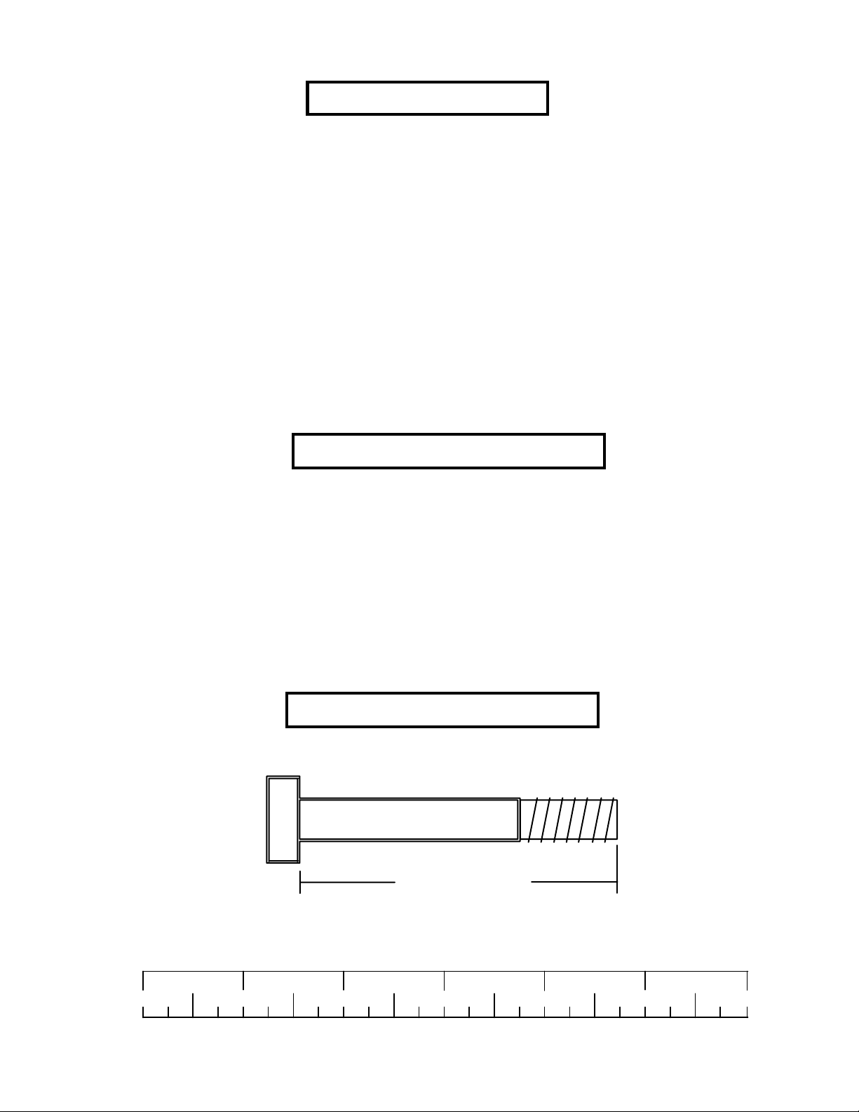
Bolt Length Ruler
NOTE: BOL T LENGTH IS MEASURED FROM THE UNDERSIDE OF THE HEAD OF THE BOLT.
BOLT LENGTH
BOL T LENGTH RULER:
1/2 1/2 1/2 1/2 1/2 1/2
0
1
2
345
3
6
1’
2’
3’
4’
5’
6’
9’1’ 2’ 3’ 4’ 5’ 6’ 7’ 8’
10’ 11’
7’
8’
9’
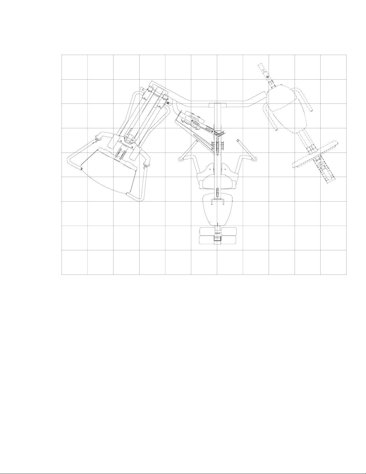
1 Square = 1’ X 1’
Minimum Required Usable Space
Length = 98 inches (250 cm) 8’ 2”
Width = 98 inches (250 cm) 8’ 2”
Height = 84 inches (213.5 cm) 7”
Dimensions Including Leg Press (optional)
Length = 98 inches (250 cm) 8’ 2”
Width = 130 inches (330 cm) 10’ 10”
4

PARTS LIST
KEY
1
2
3
4
5
6
7
8
9
10
11
12
13
14
15
16
17
18
19
20
21
22
23
24
25
26
27
28
29
30
31
32
33
34
35
36
37
38
39
40
41
42
43
44
45
46
47
PA R T #
7139708
7139808
6994721
7145002
6523401
7139908
6940808
7140108
7140208
7129508
7075808
7149308
7061608
7061308
7061808
7076208
7140302
7140402
6549301
7012102
6773802
6995708
7141608
7141708
7136108
7141802
7141902
7142002
71370
7135602
71366
7141008
7141108
7141202
7141308
7133402
7133708
7133808
7245908
7141508
7149808
7149908
3116101
3116201
6993701
6389701
7165902
DESCRIPTION
FRAME
LEG PEDEST AL
PEC ST A TION P AD
SEA T ADJUST
GUIDE ROD
REAR UPRIGHT
PULLEY PLATE
BOOM BRACKET
BASE FRAME
BOOM PLA TE
BASE PLA TE
16-1/4” TUBE
RIGHT PEC ARM
LEFT PEC ARM
PEC PLA TE
FLOA TING PULLEY BRACKET
RIGHT PEC HANDLE
LEFT PEC HANDLE
3/4” X 17” TUBE
WEIGHT ST ACK SP ACERS
LA T BAR
BOTTOM PULLEY PLATE
BENCH FRAME
BENCH FOOT
ROCKER PIVOT
BACK P AD SUPPOR T
BENCH ROCKER
BENCH SEA T ADJUST
BENCH SEA T PAD
BENCH BRACKET
BENCH BACK P AD
PRESS FRAME
PRESS EXTERIOR ADJUST
PRESS INTERIOR ADJUST
PRESS PIVOT
FOOT PLA TE
PRESS ADJUST BRACKET
PRESS ARM
RIGHT PRESS HANDLE
LEFT PRESS HANDLE
RIGHT SQUA T ARM
LEFT SQUA T ARM
4-1/2” PULLEY
3-1/2” PULLEY
4-1/2” V -GROOVE PULLEY
LOW ROW BAR
PRESS/LEG CABLE
QTY
1
1
2
1
2
1
4
1
1
1
2
1
1
1
1
1
1
1
3
2
1
3
1
1
1
1
1
1
1
1
1
1
1
1
1
1
2
1
1
1
1
1
3
20
1
1
1
48
49
50
51
52
53
54
55
56
57
58
59
60
61
62
63
64
65
66
67
68
69
70
71
72
73
74
75
76
77
78
79
80
81
82
83
84
85
86
87
88
89
90
91
92
93
94
PART #
7041802
7156002
6535603
6953702
3103801
3104901
6020601
6480301
6480302
6122701
6122702
3103302
3105401
6075906
6972201
3108901
6866601
6866801
3116001
3108002
6140701
6817101
6375801
6382301
6409101
6416601
6892501
7095701
3221702
7143401
7115201
3102503
3102501
3102507
3102802
3102807
3102801
3102804
3110001
3102909
3102924
3102903
3102922
3102904
3102915
3102905
3102906
3/8 X 9/16” FLANGE SPACER
3/8 X 1-1/16” FLANGE SPACER
1-1/4” SQ RUBBER BUMPER
1-5/8” X 5-1/2” NON-SKID STRIP
WEIGHT PLATE BUSHING (10CT)
3/8” LOW HEIGHT LOCK NUT
1/2” LOW HEIGHT LOCK NUT
KEY
5
DESCRIPTION
WEIGHT ST ACK CABLE
LA T CABLE
PEC CABLE
HEAD PLA TE
SNAP LINK
3/4” FLANGE BEARING
1/2” FLANGE BEARING
3/8 X 1” SPACER
3/8 X 1/2” SPACER
13/16” SHAFT COLLAR
3/4” ST ARLOCK
12 LINK CHAIN
WEIGHT SELECTOR PIN
2” PLASTIC WASHER
BLACK RH CAP
1/2” RH WASHER
WEIGHT ST ACK CUSHION
1” SQ. GLIDE
AB CRUNCH STRAP
ANKLE STRAP
P ARAGLIDE (QTY 8)
FLOOR ROLLER WHEEL
WEIGHT PLA TE SHAFT
3/4” E-RING,
PLUNGER PIN
SPRING PIN ASSEMBLY
3/4” FLA T WASHER
3/8” FLA T WASHER
1/2” FLA T WASHER
3/8” LOCK NUT
1/2” LOCK NUT
5/16” ROLL PIN
3/8 X 1” BOLT,
3/8 X 1-3/4” BOLT
3/8 X 2-1/2” BOLT
3/8 X 2-3/4” BOLT
3/8 X 3” BOLT
3/8 X 3-1/4” BOLT
3/8 X 3-3/4” BOLT
3/8 X 4” BOLT
QTY
1
1
1
1
3
14
8
2
4
12
2
2
8
1
1
4
2
2
1
2
6
1
1
3
1
2
2
1
1
2
2
2
26
8
43
10
3
7
4
2
15
2
14
2
2
18
5
PARTS LIST
KEY
95
96
97
98
99
100
101
102
103
104
105
106
107
108
PART #
3102917
3102937
3102911
3102963
7128202
7128203
3232101
3231501
3231601
3232001
6533501
7149501
7245601
3221703
DESCRIPTION
1/2 X 4” BOLT
1/2 X 4-1/2” BOLT
1/2 X 6” BOLT
1/2 X 11” BOLT
3/4 X 6” SHAFT
3/4 X 3-5/16” SHAFT
10/32” SET SCREW
1/4” X 1-1/2” CAP SCREW
1/2” EXT. RETAINING RING
1/2” CLEVIS PIN
CABLE RET AINING CLIP
PRESS ADJUST HANDLE
REMOTE HANDLE RET AINER
3/16” EXTERNAL E-RING
QTY
1
1
4
2
1
2
2
1
3
2
3
1
1
1
KEY
7149701
109
6686301
110
6406401
111
3110006
112
3232801
113
ACU-7308601
114
6939202
115
6016401
116
6194601
117
7159801
118
3221902
119
3221903
120
3102907
121
7150001
122
PART #
DESCRIPTION
HANDLE PIVOT PIN
1/2” U PIN
HINGE T AB
1/8” ROLL PIN
BUMPER CAP
WEIGHT ST ACK LABELS
WEIGHT PLA TES
PRESS ROLLER P AD
LEG ROLLER P AD
THREADED HOUSING
2” NYLON SP ACER
3” NYLON SP ACER
3/8 X 6” BOLT
PUSH-PULL CABLE
QTY
1
1
2
1
1
1
15
2
6
1
2
2
1
1
6
6
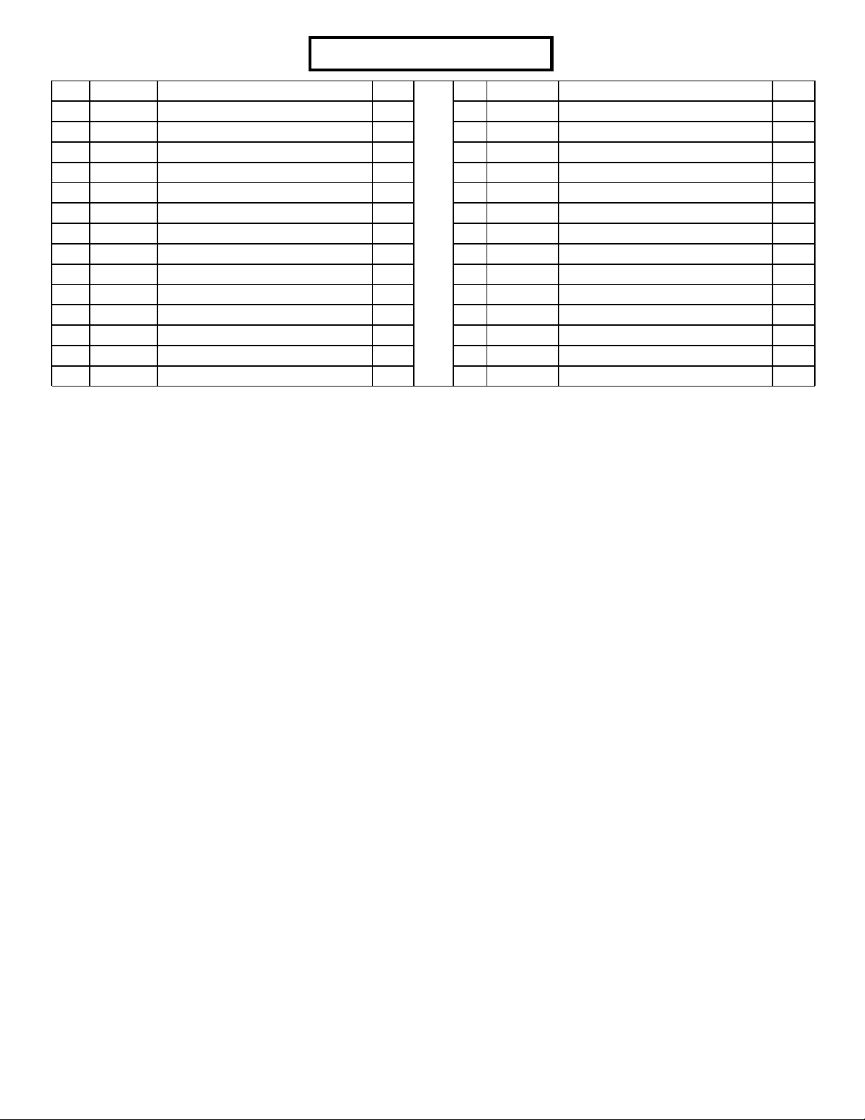
93 3/8 X 3-3/4”
94 3/8 X 4”
9
3/8 X 4” 94
80
82
FIGURE 1
STEP 1:
• SECURELY assemble the REAR UPRIGHT (6) to the BASE FRAME (9) using two 3/8 X 3-3/4” BOLTS (93), two 3/8 X 4”
BOLTS (94), six 3/8” WASHERS (80) and four 3/8” LOCK NUTS (82) as shown in FIGURE 1.
1/2 1/2 1/2 1/2 1/2 1/2
0
1
2
345
6
7
82
11
3/8 X 3-3/4” 93
6
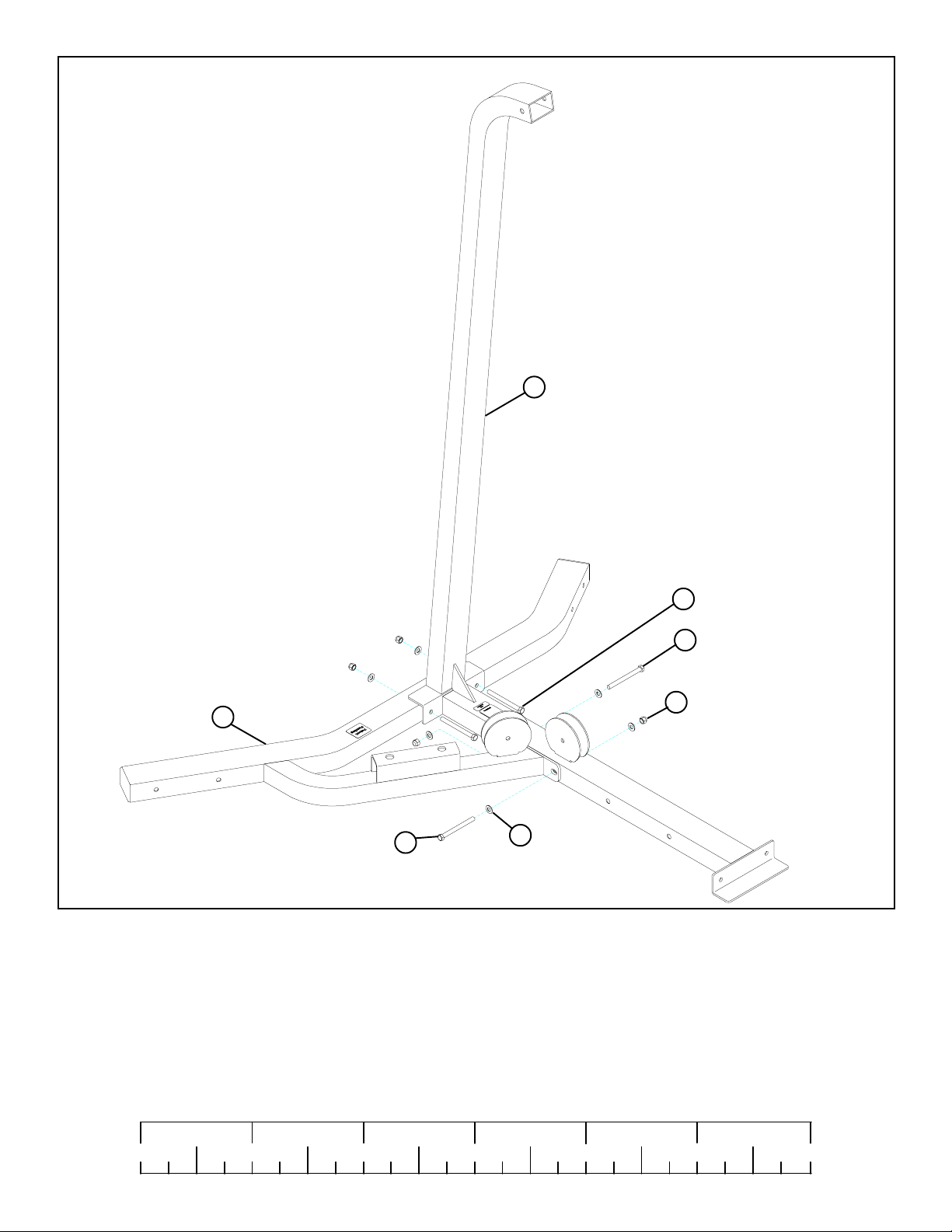
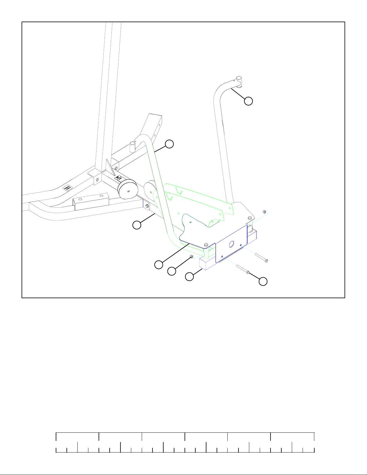
FIGURE 2
STEP 2:
• LOOSELY assemble two BASE PLATES (1 1) to the REAR UPRIGHT (6) using two 3/8 X 3-3/4” BOLTS (93) and two 3/8” LOCK
NUTS (82). See FIGURE 2.
1/2 1/2 1/2 1/2 1/2 1/2
0
1
2
345
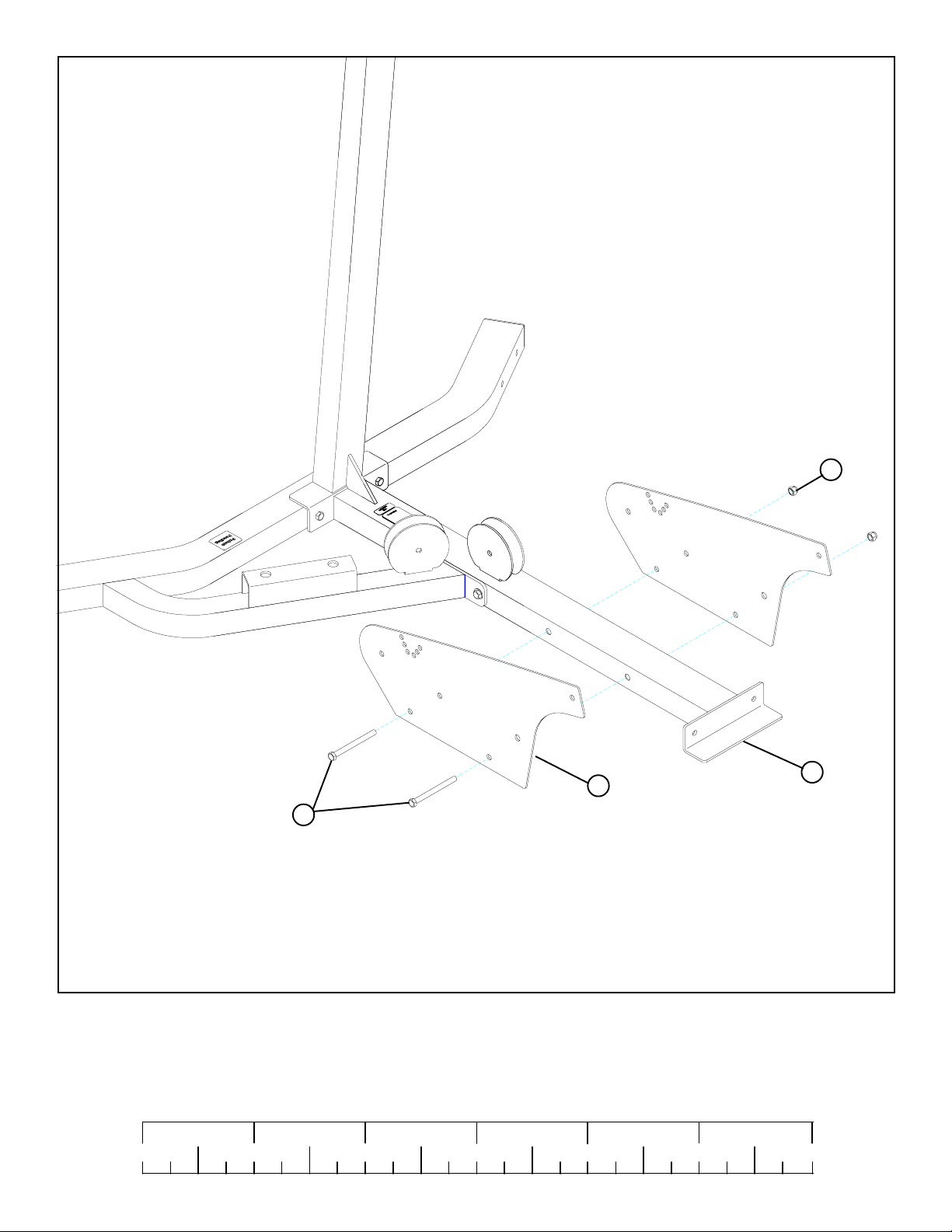
8
6
13
LOW HEIGHT 85
14
15
53
100
68
53
12
81
97 1/2 X 6”
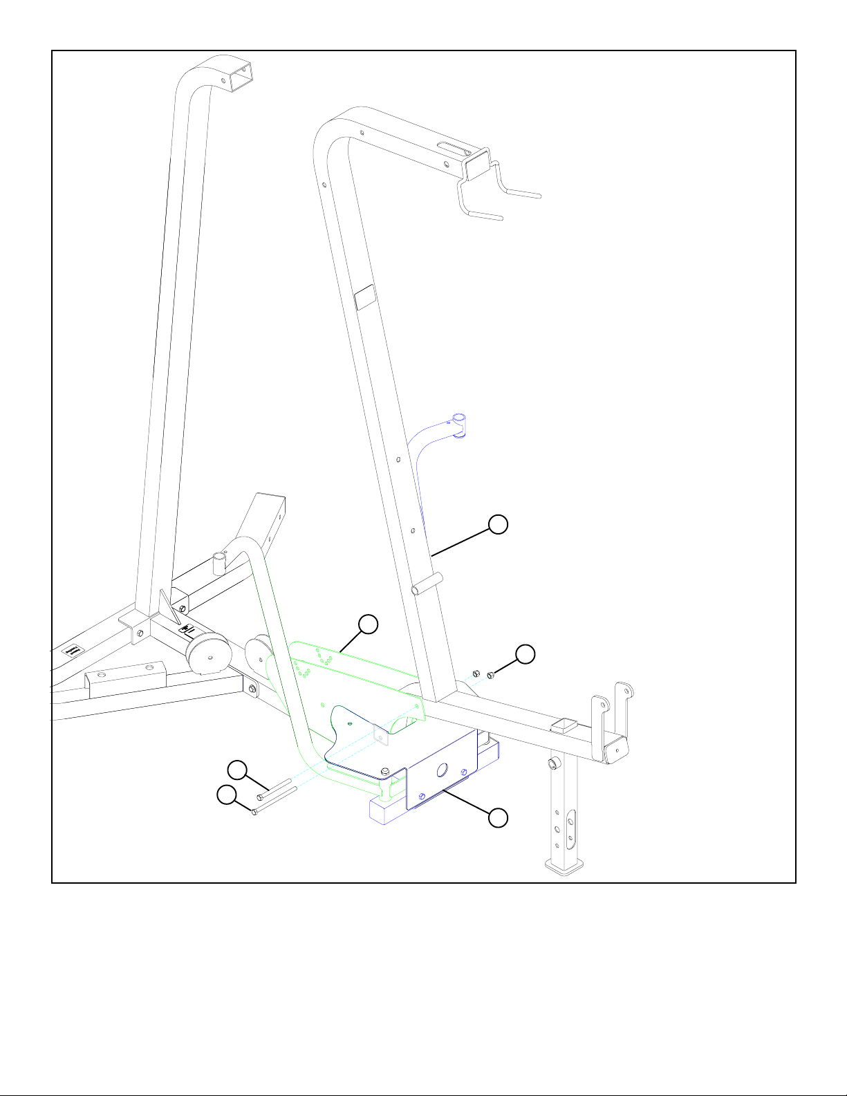
FIGURE 3
STEP 3:
• Assemble one 1” SQ. GLIDE (68) to the RIGHT PEC ARM (13) and one 1” SQ. GLIDE (68) to the LEFT PEC ARM (14) as shown
in FIGURE 3.
• Assemble the RIGHT PEC ARM (13) and LEFT PEC ARM (14) to the 16-1/4” TUBE (12) and PEC PLATE (15) using two 1/2
X 6” BOLTS (97), two 1/2” WASHERS (81), four 3/4” FLANGE BEARINGS (53), two 3/4” X 3-5/16” SHAFTS (100) and two
1/2” LOW HEIGHT LOCK NUTS (85) as shown in FIGURE 3.
9
6
14
13
15
82
12
3/8 X 2-3/4” 90
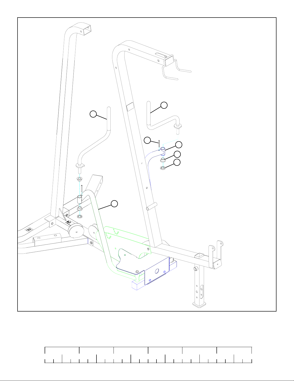
FIGURE 4
STEP 4:
• SECURELY assemble the PEC PLATE (15) and the 16-1/4” TUBE (12) to the REAR UPRIGHT (6) using two 3/8 X 2-3/4”
BOLTS (90) and two 3/8” LOCK NUTS (82) as shown in FIGURE 4.
1/2 1/2 1/2 1/2 1/2 1/2
0
1
2
345
10
6
1
11
82
3/8 X 3-3/4” 93
3/8 X 4” 94
15
FIGURE 5
STEP 5:
• SECURELY assemble the PEC PLATE (15) and the BASE PLATES (11) to the FRAME (1) using one 3/8 X 3-3/4” BOLT (93),
one 3/8 X 4” BOLT (94) and two 3/8” LOCK NUTS (82) as shown in FIGURE 5.
11
17
18
13
86
14
53
60
FIGURE 6
STEP 6:
• Assemble the LEFT PEC ARM (14) to the LEFT PEC HANDLE (18) using two 3/4” FLANGE BEARINGS (53), one STARLOCK
COLLAR (60) and one 5/16” ROLL PIN (86) as shown in FIGURE 6.
• Repeat the previous steps to assemble the RIGHT PEC HANDLE (17) and the RIGHT PEC ARM (13) as shown in FIGURE 6.
1/2 1/2 1/2 1/2 1/2 1/2
0
1
2
345
12
6
71
115
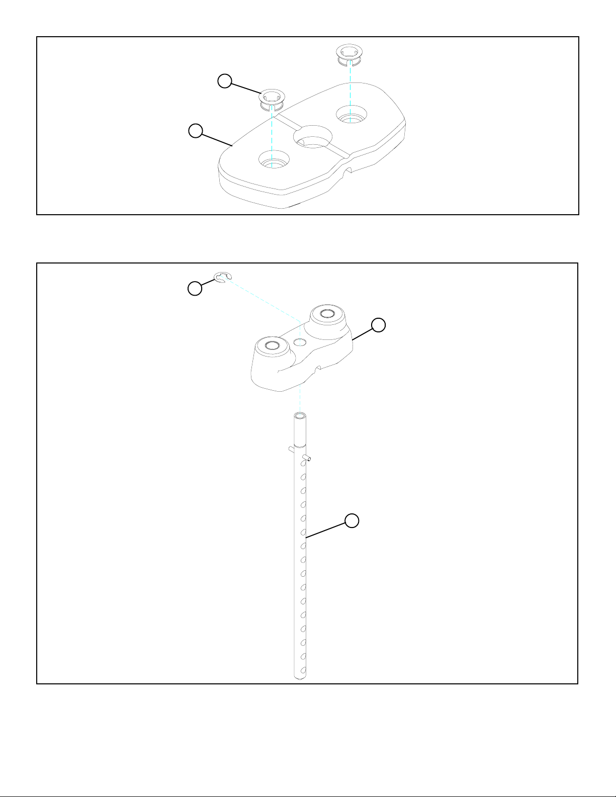
FIGURE 7
STEP 7:
• Insert two WEIGHT PLATE BUSHINGS (71) into each of the fifteen WEIGHT PLATES (115) as shown in FIGURE 7.
76
51
75
FIGURE 8
STEP 8:
• Slide the WEIGHT PLATE SHAFT (75) thru the hole in the HEAD PLATE (51), and lock in place using one E-RING (76) as shown
in FIGURE 8.
13
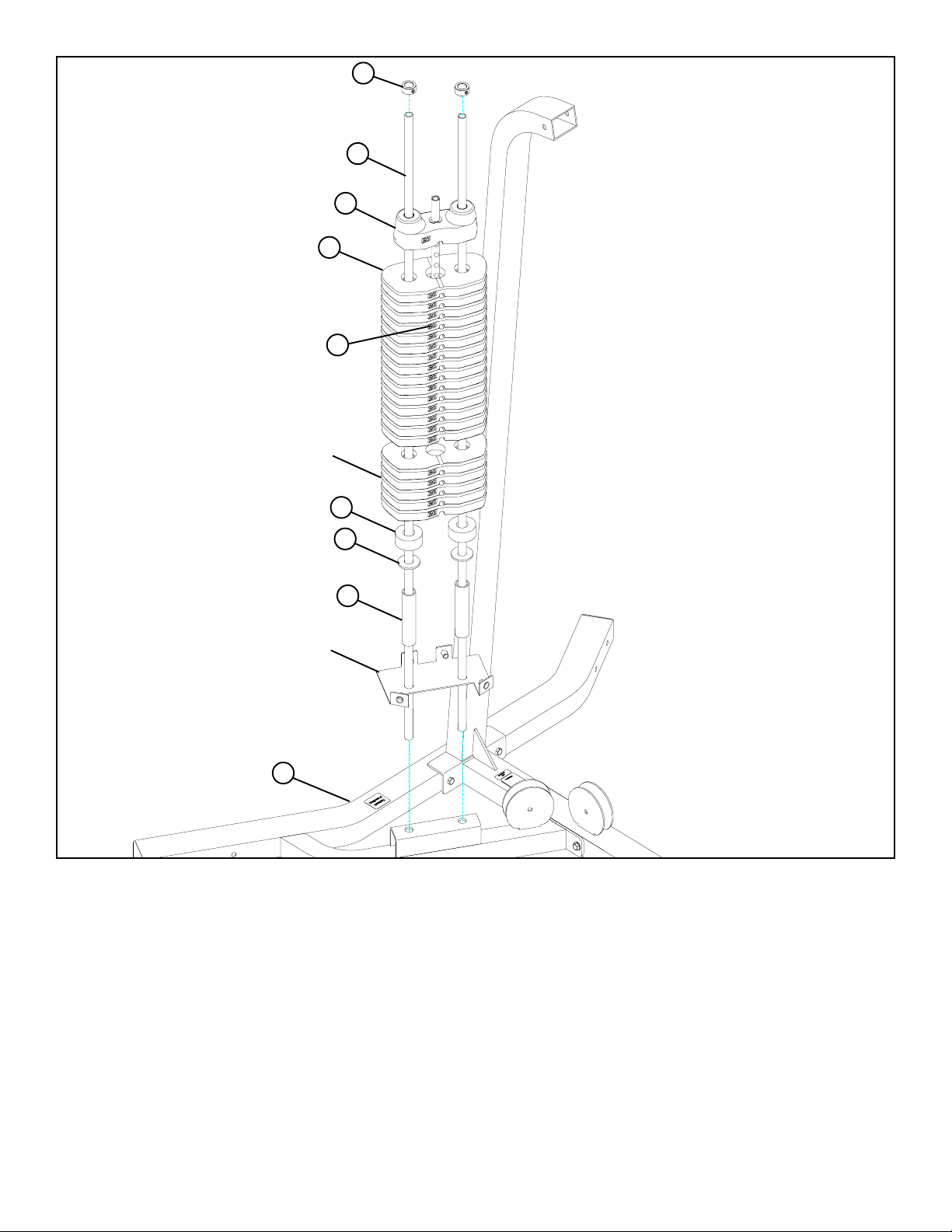
FIGURE 9
59
5
51
115
114
OPTIONAL 50
LB. ADD-ON KIT
67
79
20
880 SHROUD
OPTION ONL Y!
9
STEP 9:
• Insert two GUIDE RODS (5) into the BASE FRAME (9) as shown on FIGURE 4. (NOTE: If the 880 SHROUD OPTION was
purchased, place the GUIDE RODS (5) through the BOTTOM SHROUD BRACKET (found in SHROUD OPTION box)
and into the BASE FRAME (9) as shown in FIGURE 9.
• (NOTE: Lubricate GUIDE RODS (5) with silicon or teflon spray available at most hardware stores.)
• Slide two WEIGHT STACK SPACERS (20), two 3/4” FLAT WASHERS (79), and two WEIGHT STACK CUSHIONS (67) down
over the GUIDE RODS (5).
• Using EXTREME CARE slide all fifteen WEIGHT PLATES (1 15) (NOTE: If 50-LB. ADD-ON KIT was pur chased, slide twenty
WEIGHT PLA TES and discard two WEIGHT STACK SPACERS (20), two 3/4” FLAT WASHERS (79) use the 50 LB. ADDON HEAD PLATE and refer to the 50 LB. ADD-ON Kit instructions) down over the GUIDE RODS (5) on to the WEIGHT
STACK CUSHIONS (67). Make sure that the WEIGHT PLATES (115) are all facing as shown.
• Slide the head plate assembly down over the GUIDE RODS (5) onto the weight stack.
• Slide two SHAFT COLLARS (59) over the GUIDE RODS (5) as shown in FIGURE 9.
• Apply WEIGHT STACK LABELS (114) to WEIGHT PLATES (115) and HEAD PLATE (51) as shown in FIGURE 9. Begin with
number one at the HEAD PLATE (51) with larger numbers in consecutive order towards bottom of weight stack.
14
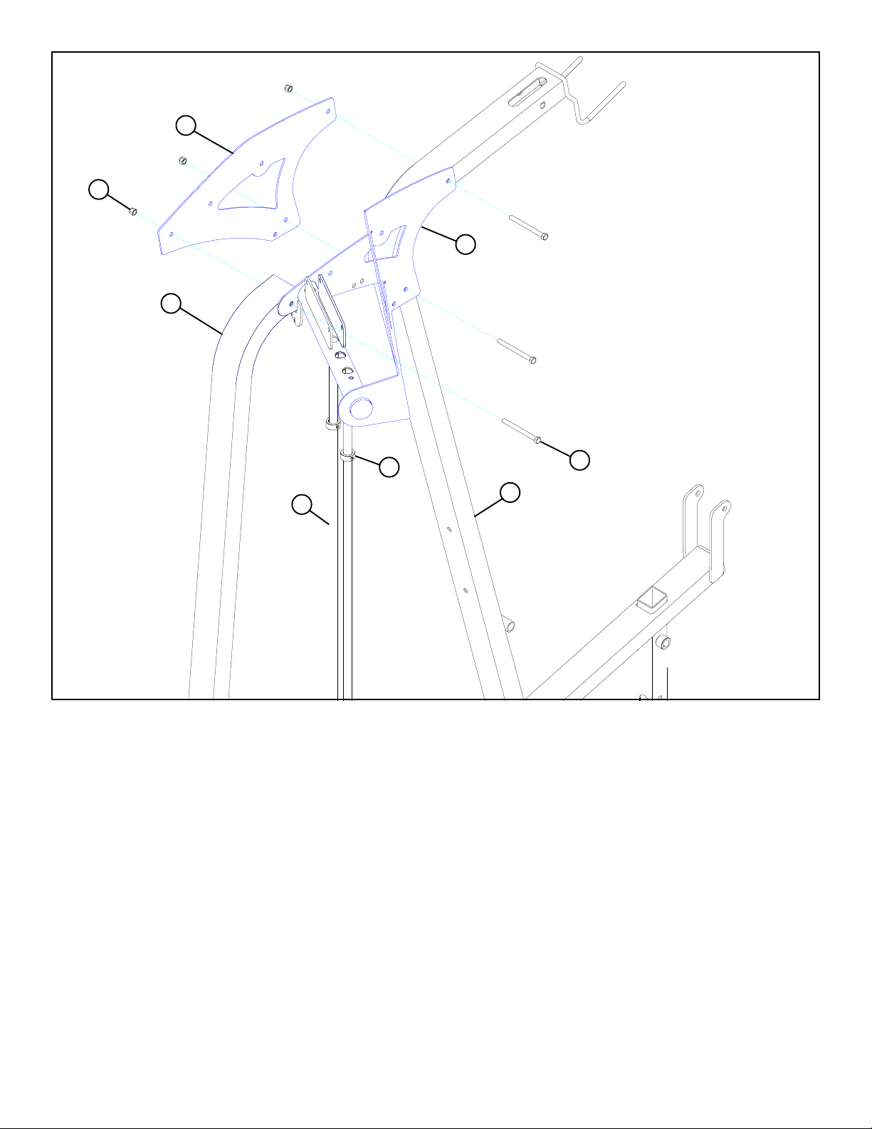
FIGURE 10
82
6
10
8
59
1
5
STEP 10:
• Swing the GUIDE RODS (5) into the guide rod bushings in the BOOM BRACKET (8) as shown in FIGURE 10.
• LOOSELY assemble the BOOM BRACKET (8) and the BOOM PLATE (10) to the REAR UPRIGHT (6) and the FRAME (1) using
three 3/8 X 3-3/4” BOLTS (93) and three 3/8” LOCK NUTS (82). See FIGURE 10.
93 3/8 X 3-3/4”
15
 Loading...