

Page 1
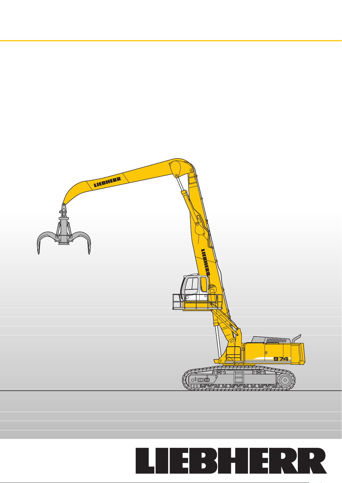
Machine for Industrial Applications
Operating Weight: 110,300 – 120,600 kg
Engine Output: 400 kW / 543 HP
R 974 C
li tr on ic
`
Page 2
Technical Data
Engine
Rating per ISO 9249
�������������������������������
Model
��������������������������������
Type
Bore/Stroke
Displacement
Engine operation
�����������������������������
Cooling
Air cleaner
Fuel tank
Electrical system
Voltage
Batteries
Starter
Alternator
�������������������������
���������������������������
�������������
������������������
����������������
�����������������
�����������������������
����������������������
������������������������
���������������������
Hydraulic System
Hydraulic pumps
for attachment and
travel drive
Max. flow
Max. hydr. pressure
Pump control
Hydraulic pump
for swing drive
Max. flow
Max. hydr. pressure
Hydraulic tank
Hydraulic system
Hydraulic oil filter
Cooler
MODE selection
ECO
POWER
LIFT
FINE
RPM adjustment
Menu for auxiliary functions
�������������������
���������������������
���������������������
���������������������
������������������������������
���������������������������
�����������������������
���������������������������
��������������������������
��������
��������������
��������
��������������������
�����������������
�����������������
������������������
�����������������
400 kW (543 HP) at 1,800 RPM
Liebherr D 9508
8 cylinder V-engine
128/157 mm
16.16 l
4-stroke diesel
Common-rail-injection
turbo-charged
after-cooled
reduced emissions
water-cooled
dry-type air cleaner with pre-cleaner, primary and
safety elements, automatic dust discharge
1,460 l
24 V
2 x 170 Ah/12 V
24 V/7.8 kW
three phase current 28 V/80 A
2 Liebherr variable flow swash plate pumps
2 x 496 l/min.
350 bar
electro-hydraulic with electronic engine speed
sensing regulation over entire RPM range,
pressure compensation, flow compensation
automatic oil flow optimizer, flow summation
1 reversible swash plate pump, closed-loop
circuit
315 l/min.
350 bar
745 l
1,350 l
2 full flow filters in return line with integrated fine
filter area (5 µm), 1 high pressure filter for each
main pump
radiator, consisting of cooling unit for coolant and
after-cooler as well as 2nd cooler for hydraulic oil
with hydrostatically regulated fan drive
adjustment of machine performance and the
hydraulics via a mode selector to match applica-
tion
for especially economical and environmentally
friendly operation
for maximum digging power and heavy duty jobs
for lifting
for precision work and lifting through very sensi-
tive movements
stepless adjustment of engine output via the rpm
at each selected mode
����
4 fixed adjustable oil flow parameters for optional
working tools
Swing Drive
����������������������������
Drive by
Transmission
Swing ring
Swing speed
Swing torque
Holding brake
Option
����������������������
�������������������������
����������������������
����������������������
���������������������
������������������������������
Uppercarriage
������������������������������
Design
Attachment mounting
���������������������������
Catwalks
�����������
Operator’s Cab
���������������������������������
Cab
Operator’s seat
Joysticks
Monitoring
Heating system
Noise emission
ISO 6396
2000/14/EC
�������������������
���������������������������
�������������������������
�������������������
���������������������������
������������������������
Undercarriage
����������������������������������
EW
��������������������������������
Drive
Transmission
Travel speed
Drawbar pull max.
Track components
Track rollers/Carrier rollers
Track pads
Digging locks
Brake valves
����������������������
����������������������
����������������
���������������
������������������������
���������������������
����������������������
Liebherr swash plate motor with integrated brake
valves
Liebherr compact planetary reduction gear
Liebherr, sealed single race ball bearing swing
ring, internal teeth
0 – 5.9 RPM stepless
295 kNm
wet multi-disc (spring applied, pressure released)
pedal controlled positioning brake
torque resistant modular design upper frame
parallel length girders
on both sides
profiles and deep drawn technology, resiliently
mounted, sound insulated, tinted windows. Front
window armored glass, door with sliding window
shock absorbing suspension, adjustable to
operator’s weight, 6-way adjustable seat
integrated into adjustable seat consoles
menu driven query of current operating condi-
tions via the LCD display. Automatic monitoring,
display, warning (acoustical and optical signal)
and saving machine malfunction data, for exam-
ple, engine overheating, low engine oil pressure
or low hydraulic oil level
standard automatic air conditioning, combined
cooler/heater, additional dust filter in fresh air/
recirculated
LpA (inside cab) = 72 dB(A)
LWA (surround noise) = 109 dB(A)
heavy version, long undercarriage, extra wide
Liebherr swash plate motors with integrated
brake valves on both sides
Liebherr planetary reduction gears
low range – 2.1 km/h
high range – 3.6 km/h
867 kN
D 9 G, maintenance-free
�����
11/2
double-grouser beveled or flat pads
wet multi-discs (spring applied, pressure
released)
integrated into travel motor
Hydraulic Controls
Power distribution
Flow summation
Closed-loop circuit
Activation
Attachment and swing
Travel
Additional functions
2 R 974 C Litronic Machine for Industrial Applications
����������������
������������
��������������������������
�������������������������
���������
�����
��������������
via control valves in single block with integrated
safety valves
to boom stick and bucket cylinders
for uppercarriage swing drive
electro-hydraulic control
proportional via joystick levers
proportional via foot pedals or removable hand
levers
via foot pedals or joystick toggle switch
Attachment
��������������������������������
Type
Hydraulic cylinders
�������������������������������
Pivots
Pivots bucket-to-stick
bucket-to-link
Lubrication
Hydraulic connections
���������������
���������������������
������������������������
box-type, combination of resistant steel plates
and cast steel components
Liebherr cylinders with special seal-system,
shock absorbed
sealed, low maintenance
O-ring sealed and completely enclosed
automatic central lubrication system
�����������
pipes and hoses equipped with SAE split-flange
connections
Page 3
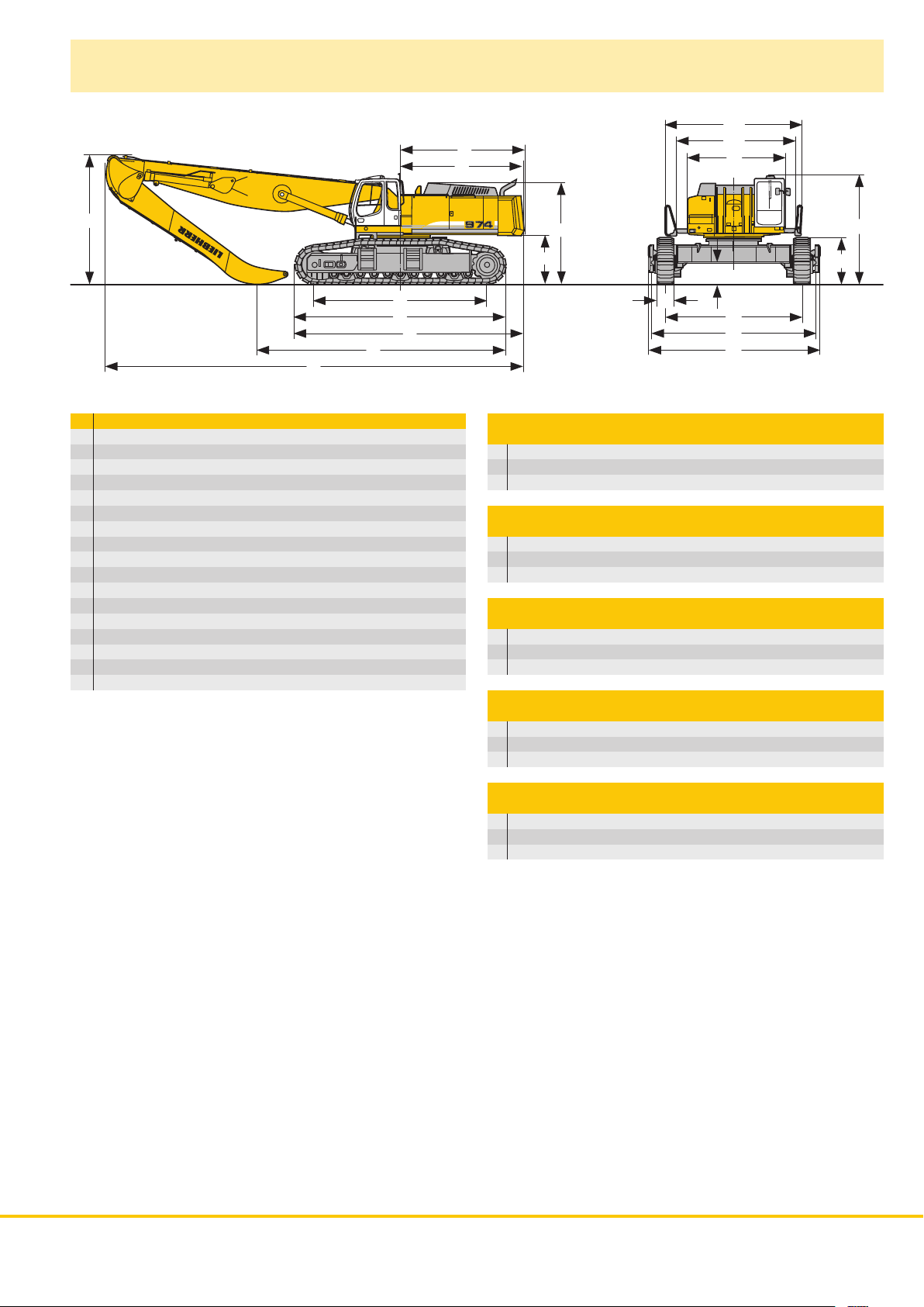
Dimensions
A2
E
D
A1
A
W
L
U
Z
V
X
mm
A 3,605
A1 4,365
A2 5,000
C 3,995
D 4,500
E 4,540
H 3,710
K 1,790
L 6,320
P 1,680
Q 780
S 5,000
U 7,720
N 600 750 1,000
B 6,000 6,000 6,000
G 6,290 6,290 6,290
Z 8,370
H
K
Q
N
S
B
G
C
P
Industrial-Type Straight Boom 10.00 m
and Industrial Stick 7.50 m mm
V 9,050
W 4,750
X 15,250
Industrial-Type Straight Boom 12.00 m
and Industrial Stick 9.00 m mm
V 10,000
W 6,250
X 17,100
Industrial-Type Gooseneck Boom 12.00 m
and Industrial Stick 9.00 m mm
V 9,250
W 4,750
X 17,250
Industrial-Type Straight Boom 14.00 m
and Industrial Stick 10.50 m mm
V 10,900
W 7,700
X 18,850
Industrial-Type Gooseneck Boom 14.00 m
and Industrial Stick 10.50 m mm
V 10,000
W 5,450
X 19,200
R 974 C Litronic Machine for Industrial Applications 3
Page 4
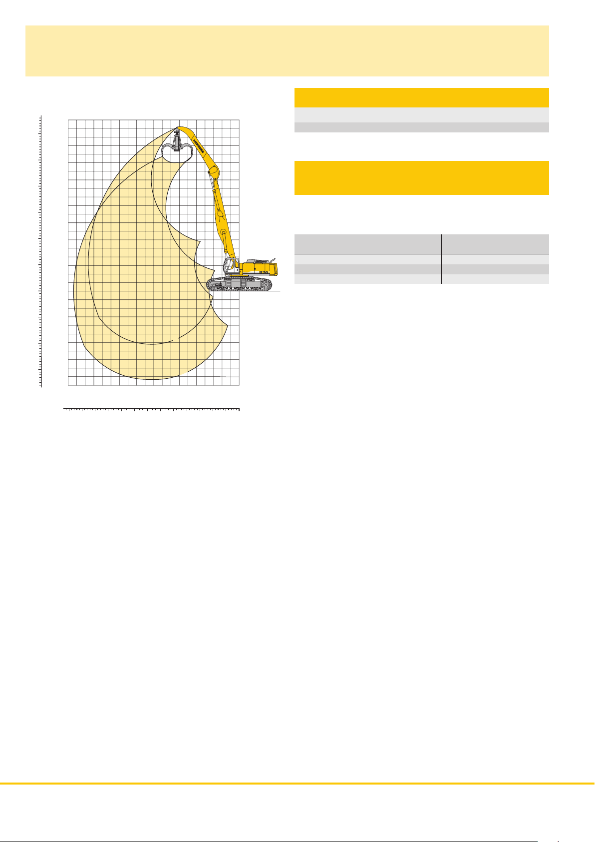
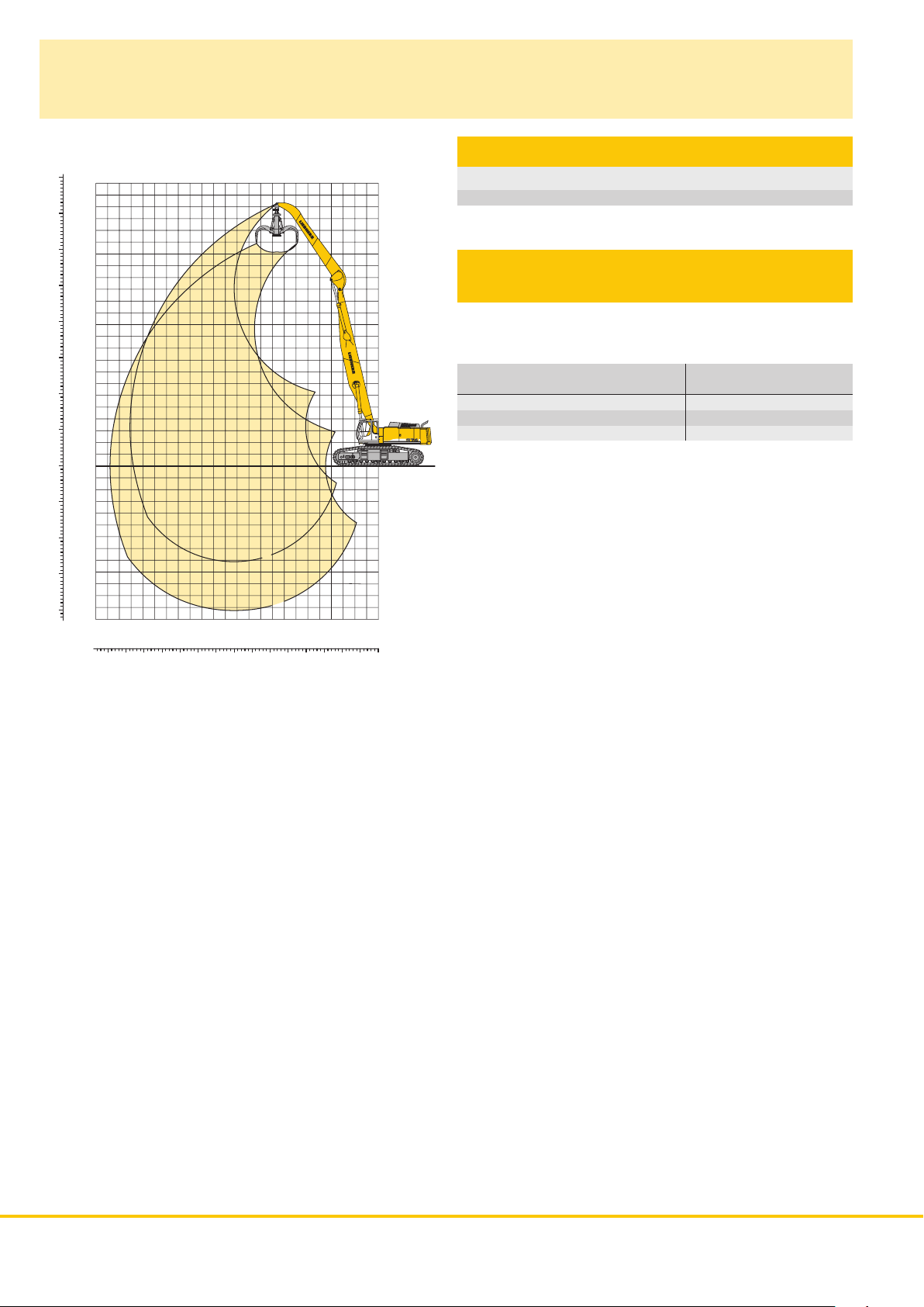
Industrial Attachment
with Industrial-Type Straight Boom 10.00 m
ft
m
Attachment Envelope
60
50
40
30
20
10
-10
-20
-30
20
18
16
14
12
10
8
6
4
2
0
0
-2
-4
-6
-8
-10
1
2
02468101214161820
m
1 with industrial stick 7.50 m
2 with industrial stick 7.50 m and grapple model 75 B
Operating Weight
and Ground Pressure
The operating weight includes basic machine with counterweight
18.0 t, industrial-type straight boom 10.00 m, industrial stick 7.50 m
and grapple model 75 B with 5 open tines 3.00 m
Undercarriage EW
Pad width mm 600 750 1,000*
Weight kg 110,300 111,800 117,200
Ground pressure kg/cm
* flat pads
2
1.45 1.18 0.93
3
.
ft
0102030405060
4 R 974 C Litronic Machine for Industrial Applications
Page 5
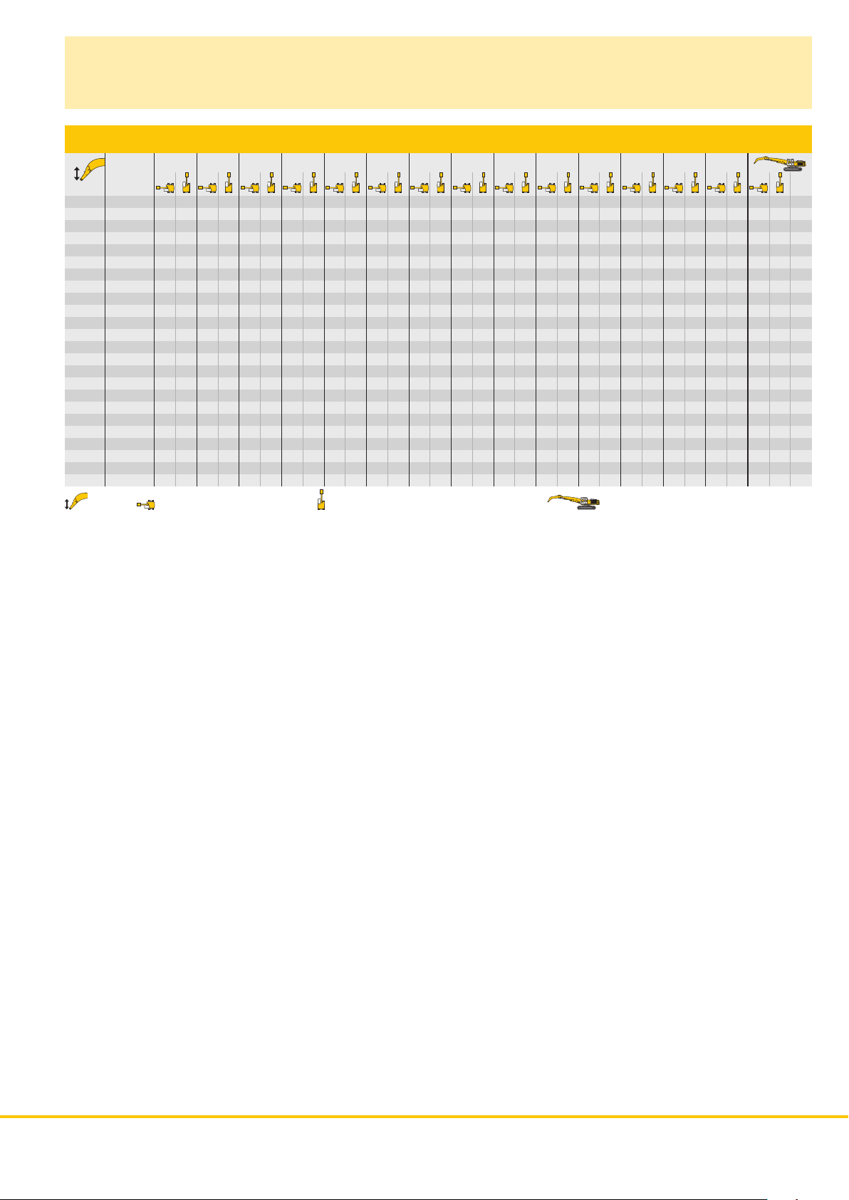
Lift Capacities
with Industrial-Type Straight Boom 10.00 m
Industrial Stick 7.50 m
4.5 m 6.0 m 7.5 m 9.0 m 10.5 m 12.0 m 13.5 m 15.0 m 16.5 m 18.0 m 19.5 m 21.0 m 22.5 m 24.0 m
Under m carriage m
24.0 EW
22.5 EW
21.0 EW
19.5 EW
18.0 EW
16.5 EW
15.0 EW
13.5 EW
12.0 EW
10.5 EW
9.0 EW
7.5 EW
6.0 EW
4.5 EW
3.0 EW
1.5 EW
0 EW
– 1.5 EW
– 3.0 EW
– 4.5 EW
– 6.0 EW
– 7.5 EW
– 9.0 EW
– 10.5 EW
17.9* 17.9* 16.0* 16.0* 9.42
18.0* 18.0* 13.8* 13.8* 11.52
18.2* 18.2* 17.4* 17.4* 12.6* 12.6* 13.09
17.8* 17.8* 17.2* 17.2* 16.1* 16.1* 11.8* 11.8* 14.33
17.9* 17.9* 17.1* 17.1* 16.5* 16.5* 13.4* 13.4* 11.3* 11.3* 15.32
18.3* 18.3* 17.4* 17.4* 16.6* 16.6* 16.0* 16.0* 10.9* 10.9* 16.10
19.1* 19.1* 17.9* 17.9* 16.9* 16.9* 16.1* 16.1* 12.4* 12.4* 10.8* 10.8* 16.70
22.2* 22.2* 20.2* 20.2* 18.6* 18.6* 17.4* 17.4* 16.2 16.3* 13.8 15.4* 10.7* 10.7* 17.15
33.8* 33.8* 28.0* 28.0* 24.2* 24.2* 21.5* 21.5* 19.5* 19.5* 17.9* 17.9* 16.0 16.7* 13.7 15.6* 10.7* 10.7* 17.45
39.6* 39.6* 31.4* 31.4* 26.3* 26.3* 22.9* 22.9* 20.4* 20.4* 18.4 18.6* 15.7 17.1* 13.6 15.8* 10.8* 10.8* 17.62
29.2* 29.2* 34.4* 34.4* 28.3* 28.3* 24.2* 24.2* 21.3* 21.3* 18.0 19.1* 15.4 17.4* 13.4 15.9* 11.0* 11.0* 17.65
16.4* 16.4* 36.7* 36.7* 29.9* 29.9* 25.3 25.3* 20.9 22.0* 17.7 19.6* 15.2 17.6* 13.3 15.9* 11.3* 11.3* 17.56
6.5* 6.5* 15.1* 15.1* 35.9* 35.9* 30.8 30.8* 24.7 26.0* 20.5 22.5* 17.4 19.8* 15.0 17.7* 13.2 15.6* 11.8* 11.8* 17.33
9.4* 9.4* 16.5* 16.5* 31.8* 31.8* 30.2 31.1* 24.3 26.2* 20.2 22.6* 17.2 19.8* 14.9 17.4* 13.2 14.9* 12.4* 12.4* 16.96
12.5* 12.5* 18.9* 18.9* 32.0* 32.0* 30.0 30.5* 24.1 25.8* 20.0 22.2* 17.1 19.2* 14.9 16.6* 13.2* 13.2* 16.44
21.8* 21.8* 34.4* 34.4* 29.0* 29.0* 24.1 24.6* 20.0 21.1* 17.2 18.0* 14.9* 14.9* 14.7* 14.7* 15.07
26.4* 26.4* 22.5* 22.5* 19.0* 19.0* 18.9* 18.9* 12.06
Height Can be slewed through 360° In longitudinal position of undercarriage Max. reach * Limited by hydr. capacity
The lift capacities are stated in metric tonnes (t) on the lifting gear’s stick tip, and can be lifted 360° on firm, level supporting surface. Capacities
are valid for 600 mm wide double grouser pads. Indicated loads are based on ISO 10567 standard and do not exceed 75 % of tipping or 87 % of
hydraulic capacity (indicated via *). Lifting capacity of the excavator is limited by machine stability, hydraulic capacity and maximum permissible
load of the load hook.
According to European Standard, EN 474-5: In the European Union excavators have to be equipped with an overload warning device, a load
diagram and automatic check valves on the hoist cylinders, when they are used for lifting operations which require the use of lifting accessories.
R 974 C Litronic Machine for Industrial Applications 5
Page 6
Industrial Attachment
with Industrial-Type Straight Boom 12.00 m
ft
80
70
60
50
40
30
20
10
-10
-20
-30
-40
m
24
22
20
18
16
14
12
10
8
6
4
2
0
0
-2
-4
-6
-8
-10
-12
1
2
024681012141618202224
m
Attachment Envelope
1 with industrial stick 9.00 m
2 with industrial stick 9.00 m and grapple model 75 B
Operating Weight
and Ground Pressure
The operating weight includes basic machine with counterweight
18.0 t, industrial-type straight boom 12.00 m, industrial stick 9.00 m
and grapple model 75 B with 5 open tines 2.50 m
Undercarriage EW
Pad width mm 600 750 1,000*
Weight kg 111,900 113,400 118,800
Ground pressure kg/cm
* flat pads
3
.
2
1.48 1.20 0.94
ft
010203040506070
6 R 974 C Litronic Machine for Industrial Applications
Page 7

Lift Capacities
with Industrial-Type Straight Boom 12.00 m
Industrial Stick 9.00 m
4.5 m 6.0 m 7.5 m 9.0 m 10.5 m 12.0 m 13.5 m 15.0 m 16.5 m 18.0 m 19.5 m 21.0 m 22.5 m 24.0 m
Under m carriage m
24.0 EW
22.5 EW
21.0 EW
19.5 EW
18.0 EW
16.5 EW
15.0 EW
13.5 EW
12.0 EW
10.5 EW
9.0 EW
7.5 EW
6.0 EW
4.5 EW
3.0 EW
1.5 EW
0 EW
– 1.5 EW
– 3.0 EW
– 4.5 EW
– 6.0 EW
– 7.5 EW
– 9.0 EW
– 10.5 EW
14.9* 14.9* 13.1* 13.1* 11.08
15.0* 15.0* 11.5* 11.5* 13.26
14.7* 14.7* 14.1* 14.1* 10.5* 10.5* 14.96
13.7* 13.7* 13.2* 13.2* 9.8* 9.8* 16.34
13.5* 13.5* 13.0* 13.0* 12.6* 12.6* 9.3* 9.3* 17.47
13.5* 13.5* 12.9* 12.9* 12.4* 12.4* 10.9* 10.9* 9.0* 9.0* 18.41
14.5* 14.5* 13.7* 13.7* 13.0* 13.0* 12.4* 12.4* 12.0* 12.0* 8.8* 8.8* 19.18
15.0* 15.0* 14.0* 14.0* 13.2* 13.2* 12.5* 12.5* 12.0* 12.0* 10.3 10.3* 8.6* 8.6* 19.80
17.1* 17.1* 15.7* 15.7* 14.5* 14.5* 13.5* 13.5* 12.8* 12.8* 11.9 12.1* 10.2 11.5* 8.6* 8.6* 20.30
20.5* 20.5* 18.2* 18.2* 16.4* 16.4* 15.0* 15.0* 13.9* 13.9* 13.0* 13.0* 11.7 12.2* 10.1 11.6* 8.5* 8.5* 20.66
32.9* 32.9* 26.4* 26.4* 22.3* 22.3* 19.4* 19.4* 17.3* 17.3* 15.7* 15.7* 14.4* 14.4* 13.3 13.3* 11.5 12.4* 10.0 11.7* 8.6* 8.6* 20.92
29.3* 29.3* 24.1* 24.1* 20.7* 20.7* 18.2* 18.2* 16.3* 16.3* 14.8* 14.8* 12.9 13.6* 11.2 12.6* 9.8 11.8* 8.7 9.1* 8.6 8.7* 21.05
31.8* 31.8* 25.8* 25.8* 21.8* 21.8* 19.0* 19.0* 16.9* 16.9* 14.5 15.2* 12.6 13.9* 11.0 12.8* 9.7 11.8* 8.6 9.5* 8.6 8.8* 21.08
6.2* 6.2* 18.7* 18.7* 27.1* 27.1* 22.8* 22.8* 19.5 19.7* 16.5 17.4* 14.1 15.6* 12.3 14.1* 10.8 12.9* 9.6 11.8* 8.6 9.0* 8.6 9.0* 21.00
6.7* 6.7* 15.2* 15.2* 27.9* 27.9* 22.7 23.4* 18.8 20.2* 16.0 17.7* 13.8 15.8* 12.0 14.3* 10.6 12.9* 9.5 11.7* 8.7 9.3* 20.81
4.4* 4.4* 8.2* 8.2* 14.9* 14.9* 27.4 28.2* 22.1 23.7* 18.4 20.4* 15.6 17.9* 13.5 15.9* 11.8 14.2* 10.5 12.8* 9.4 11.4* 8.8 9.7* 20.51
6.7* 6.7* 10.0* 10.0* 15.9* 15.9* 27.0 27.1* 21.7 23.6* 18.0 20.3* 15.4 17.8* 13.3 15.7* 11.7 14.0* 10.4 12.5* 9.4 10.8* 9.1 9.9* 20.08
12.1* 12.1* 17.5* 17.5* 26.9 27.0* 21.5 23.0* 17.9 19.9* 15.2 17.4* 13.2 15.3* 11.7 13.5* 10.5 11.8* 9.6 9.6* 19.48
19.4* 19.4* 25.5* 25.5* 21.6 21.9* 17.9 19.0* 15.3 16.6* 13.3 14.5* 11.7 12.6* 10.6 10.6* 10.5* 10.5* 18.06
23.3* 23.3* 20.2* 20.2* 17.6* 17.6* 15.3* 15.3* 13.2* 13.2* 12.5* 12.5* 15.55
Height Can be slewed through 360° In longitudinal position of undercarriage Max. reach * Limited by hydr. capacity
The lift capacities are stated in metric tonnes (t) on the lifting gear’s stick tip, and can be lifted 360° on firm, level supporting surface. Capacities
are valid for 600 mm wide double grouser pads. Indicated loads are based on ISO 10567 standard and do not exceed 75 % of tipping or 87 % of
hydraulic capacity (indicated via *). Lifting capacity of the excavator is limited by machine stability, hydraulic capacity and maximum permissible
load of the load hook.
According to European Standard, EN 474-5: In the European Union excavators have to be equipped with an overload warning device, a load
diagram and automatic check valves on the hoist cylinders, when they are used for lifting operations which require the use of lifting accessories.
R 974 C Litronic Machine for Industrial Applications 7
Page 8

Industrial Attachment
with Industrial-Type Gooseneck Boom 12.00 m
ft
m
Attachment Envelope
60
50
40
30
20
10
-10
-20
-30
-40
20
18
16
14
12
10
8
6
4
2
0
0
-2
-4
-6
-8
-10
-12
-14
1
2
0246810121416182022
m
1 with industrial stick 9.00 m
2 with industrial stick 9.00 m and grapple model 75 B
Operating Weight
and Ground Pressure
The operating weight includes basic machine with counterweight
18.0 t, industrial-type gooseneck boom 12.00 m, industrial stick
9.00 m and grapple model 75 B with 5 open tines 2.50 m
Undercarriage EW
Pad width mm 600 750 1,000*
Weight kg 112,200 113,700 119,100
Ground pressure kg/cm
* flat pads
2
1.48 1.20 0.94
3
.
ft
010203040506070
8 R 974 C Litronic Machine for Industrial Applications
Page 9

Lift Capacities
with Industrial-Type Gooseneck Boom 12.00 m
Industrial Stick 9.00 m
4.5 m 6.0 m 7.5 m 9.0 m 10.5 m 12.0 m 13.5 m 15.0 m 16.5 m 18.0 m 19.5 m 21.0 m 22.5 m 24.0 m
Under m carriage m
24.0 EW
22.5 EW
21.0 EW
19.5 EW
18.0 EW
16.5 EW
15.0 EW
13.5 EW
12.0 EW
10.5 EW
9.0 EW
7.5 EW
6.0 EW
4.5 EW
3.0 EW
1.5 EW
0 EW
– 1.5 EW
– 3.0 EW
– 4.5 EW
– 6.0 EW
– 7.5 EW
– 9.0 EW
– 10.5 EW
10.9* 10.9* 12.66
12.4* 12.4* 10.0* 10.0* 14.44
11.7* 11.7* 9.4* 9.4* 15.86
11.5* 11.5* 10.9* 10.9* 9.1* 9.1* 17.03
11.4* 11.4* 11.2* 11.2* 8.8* 8.8* 17.99
11.9* 11.9* 11.5* 11.5* 11.2* 11.2* 11.0* 11.0* 8.7* 8.7* 18.78
12.3* 12.3* 11.8* 11.8* 11.3* 11.3* 11.0* 11.0* 8.6* 8.6* 19.42
13.7* 13.7* 12.8* 12.8* 12.1* 12.1* 11.6* 11.6* 11.1* 11.1* 10.3 10.4* 8.5* 8.5* 19.92
15.9* 15.9* 14.5* 14.5* 13.5* 13.5* 12.6* 12.6* 11.9* 11.9* 11.3* 11.3* 10.2 10.9* 8.6* 8.6* 20.29
23.1* 23.1* 19.7* 19.7* 17.3* 17.3* 15.5* 15.5* 14.2* 14.2* 13.1* 13.1* 12.3* 12.3* 11.6 11.6* 10.1 11.1* 8.7* 8.7* 20.55
34.1* 34.1* 26.3* 26.3* 21.7* 21.7* 18.7* 18.7* 16.5* 16.5* 14.9* 14.9* 13.7* 13.7* 12.7* 12.7* 11.3 11.9* 9.9 11.2* 8.8* 8.8* 20.69
14.1* 14.1* 29.3* 29.3* 23.7* 23.7* 20.1* 20.1* 17.5* 17.5* 15.7* 15.7* 14.2* 14.2* 12.7 13.1* 11.1 12.2* 9.7 11.4* 8.8 9.1* 20.72
9.9* 9.9* 24.0* 24.0* 25.4* 25.4* 21.3* 21.3* 18.4* 18.4* 16.3* 16.3* 14.3 14.7* 12.4 13.5* 10.8 12.4* 9.6 11.6* 8.8 9.4* 20.64
4.8* 4.8* 9.7* 9.7* 18.8* 18.8* 26.7* 26.7* 22.3* 22.3* 19.0 19.2* 16.1 16.9* 13.9 15.2* 12.1 13.8* 10.6 12.6* 9.5 11.6* 8.8 9.7* 20.44
6.7* 6.7* 10.6* 10.6* 17.6* 17.6* 27.5* 27.5* 22.2 23.0* 18.4 19.8* 15.7 17.4* 13.5 15.5* 11.9 14.0* 10.5 12.7* 9.4 11.6* 9.0 10.2* 20.13
8.6* 8.6* 12.0* 12.0* 18.0* 18.0* 27.0 27.8* 21.7 23.3* 18.1 20.1* 15.4 17.6* 13.3 15.6* 11.7 14.1* 10.4 12.7* 9.4 11.3* 9.3 10.9* 19.70
10.5* 10.5* 13.7* 13.7* 19.0* 19.0* 26.8 27.6* 21.5 23.3* 17.9 20.1* 15.2 17.6* 13.2 15.6* 11.6 13.9* 10.4 12.4* 9.7 11.2* 19.13
15.3* 15.3* 20.5* 20.5* 26.9 26.9* 21.5 22.9* 17.8 19.8* 15.2 17.3* 13.2 15.3* 11.7 13.5* 10.5 11.7* 10.2 11.1* 18.43
22.3* 22.3* 25.6* 25.6* 21.6 21.9* 17.9 19.0* 15.3 16.6* 13.3 14.5* 11.8 12.6* 11.0* 11.0* 17.56
23.6* 23.6* 20.4* 20.4* 17.6* 17.6* 15.3* 15.3* 13.1* 13.1* 13.0* 13.0* 15.13
Height Can be slewed through 360° In longitudinal position of undercarriage Max. reach * Limited by hydr. capacity
The lift capacities are stated in metric tonnes (t) on the lifting gear’s stick tip, and can be lifted 360° on firm, level supporting surface. Capacities
are valid for 600 mm wide double grouser pads. Indicated loads are based on ISO 10567 standard and do not exceed 75 % of tipping or 87 % of
hydraulic capacity (indicated via *). Lifting capacity of the excavator is limited by machine stability, hydraulic capacity and maximum permissible
load of the load hook.
According to European Standard, EN 474-5: In the European Union excavators have to be equipped with an overload warning device, a load
diagram and automatic check valves on the hoist cylinders, when they are used for lifting operations which require the use of lifting accessories.
R 974 C Litronic Machine for Industrial Applications 9
Page 10

Industrial Attachment
with Industrial-Type Straight Boom 14.00 m
ft
80
70
60
50
40
30
20
10
-10
-20
-30
-40
m
26
24
22
20
18
16
14
12
10
8
6
4
2
0
0
-2
-4
-6
-8
-10
-12
-14
1
2
02468101214161820222426
m
Attachment Envelope
1 with industrial stick 10.50 m
2 with industrial stick 10.50 m and grapple model 75 B
Operating Weight
and Ground Pressure
The operating weight includes basic machine with counterweight
18.0 t, industrial-type straight boom 14.00 m, industrial stick 10.50 m
and grapple model 75 B with 5 open tines 2.00 m
Undercarriage EW
Pad width mm 600 750 1,000*
Weight kg 113,400 114,900 120,300
Ground pressure kg/cm
* flat pads
3
.
2
1.50 1.21 0.95
ft
0102030405060708090
10 R 974 C Litronic Machine for Industrial Applications
Page 11

Lift Capacities
with Industrial-Type Straight Boom 14.00 m
Industrial Stick 10.50 m
4.5 m 6.0 m 7.5 m 9.0 m 10.5 m 12.0 m 13.5 m 15.0 m 16.5 m 18.0 m 19.5 m 21.0 m 22.5 m 24.0 m
Under m carriage m
24.0 EW
22.5 EW
21.0 EW
19.5 EW
18.0 EW
16.5 EW
15.0 EW
13.5 EW
12.0 EW
10.5 EW
9.0 EW
7.5 EW
6.0 EW
4.5 EW
3.0 EW
1.5 EW
0 EW
– 1.5 EW
– 3.0 EW
– 4.5 EW
– 6.0 EW
– 7.5 EW
– 9.0 EW
– 10.5 EW
12.6* 12.6* 11.0* 11.0* 12.75
12.5* 12.5* 9.7* 9.7* 14.98
12.0* 12.0* 11.4* 11.4* 9.7* 9.7* 8.9* 8.9* 16.78
11.1* 11.1* 10.6* 10.6* 9.2* 9.2* 8.3* 8.3* 18.27
10.9* 10.9* 10.4* 10.4* 9.9* 9.9* 8.0* 8.0* 7.9* 7.9* 19.53
10.9* 10.9* 10.3* 10.3* 9.8* 9.8* 9.4* 9.4* 7.6* 7.6* 20.59
10.9* 10.9* 10.3* 10.3* 9.8* 9.8* 9.3* 9.3* 8.9 9.0* 7.4* 7.4* 21.50
11.0* 11.0* 10.4* 10.4* 9.8* 9.8* 9.3* 9.3* 8.9* 8.9* 7.2* 7.2* 22.26
12.1* 12.1* 11.2* 11.2* 10.5* 10.5* 9.9* 9.9* 9.4* 9.4* 8.9 8.9* 7.6 8.5* 7.1* 7.1* 22.90
13.6* 13.6* 12.4* 12.4* 11.5* 11.5* 10.7* 10.7* 10.0* 10.0* 9.4* 9.4* 8.8 9.0* 7.6 8.5* 6.8 7.0* 23.43
14.2* 14.2* 12.9* 12.9* 11.8* 11.8* 10.9* 10.9* 10.2* 10.2* 9.6* 9.6* 8.6 9.0* 7.5 8.5* 6.5 7.0* 23.84
19.2* 19.2* 16.7* 16.7* 14.8* 14.8* 13.3* 13.3* 12.2* 12.2* 11.2* 11.2* 10.4* 10.4* 9.7* 9.7* 8.5 9.1* 7.4 8.6* 6.4 7.7* 6.3 7.0* 24.15
25.0* 25.0* 20.7* 20.7* 17.7* 17.7* 15.5* 15.5* 13.9* 13.9* 12.5* 12.5* 11.5* 11.5* 10.6* 10.6* 9.5 9.8* 8.3 9.2* 7.2 8.6* 6.3 8.0* 6.1 7.0* 24.37
27.2* 27.2* 22.1* 22.1* 18.7* 18.7* 16.2* 16.2* 14.4* 14.4* 12.9* 12.9* 11.8* 11.8* 10.5 10.8* 9.2 10.0* 8.0 9.3* 7.1 8.7* 6.2 8.0* 6.0 7.1* 24.49
12.3* 12.3* 23.3* 23.3* 19.6* 19.6* 16.9* 16.9* 14.8* 14.8* 13.3* 13.3* 11.7 12.0* 10.2 11.0* 8.9 10.1* 7.8 9.4* 6.9 8.7* 6.2 8.0* 5.9 7.2* 24.51
8.0* 8.0* 21.2* 21.2* 20.3* 20.3* 17.4* 17.4* 15.1 15.2* 12.9 13.6* 11.2 12.2* 9.8 11.1* 8.6 10.2* 7.6 9.4* 6.8 8.7* 6.1 7.9* 5.9 7.4* 24.44
7.3* 7.3* 15.7* 15.7* 20.3 20.7* 16.9 17.8* 14.4 15.5* 12.4 13.8* 10.8 12.4* 9.5 11.2* 8.4 10.3* 7.5 9.4* 6.7 8.6* 6.1 7.7* 6.0 7.4* 24.28
4.0* 4.0* 7.8* 7.8* 14.2* 14.2* 19.5 20.9* 16.3 17.9* 13.9 15.7* 12.0 13.9* 10.5 12.5* 9.2 11.3* 8.2 10.2* 7.3 9.3* 6.6 8.4* 6.1 7.3* 6.1 7.3* 24.02
3.4* 3.4* 5.5* 5.5* 8.8* 8.8* 14.2* 14.2* 19.0 20.8* 15.8 17.9* 13.5 15.7* 11.7 13.9* 10.2 12.4* 9.0 11.2* 8.1 10.1* 7.3 9.1* 6.6 8.1* 6.2 7.1* 23.66
7.1* 7.1* 10.1* 10.1* 14.9* 14.9* 18.7 20.4* 15.6 17.6* 13.2 15.5* 11.5 13.7* 10.1 12.2* 8.9 11.0* 8.0 9.9* 7.2 8.8* 6.6 7.6* 6.4 6.9* 23.19
8.7* 8.7* 11.5* 11.5* 16.1* 16.1* 18.7 19.6* 15.4 17.1* 13.1 15.0* 11.4 13.3* 10.0 11.9* 8.9 10.6* 8.0 9.4* 7.3 8.3* 6.7* 6.7* 22.49
13.1* 13.1* 17.5* 17.5* 18.6* 18.6* 15.5 16.3* 13.1 14.3* 11.4 12.7* 10.0 11.3* 8.9 10.0* 8.1 8.8* 7.4* 7.4* 7.3* 7.3* 21.06
17.1* 17.1* 15.1* 15.1* 13.3 13.3* 11.5 11.8* 10.1 10.4* 9.1 9.1* 8.4* 8.4* 18.76
Height Can be slewed through 360° In longitudinal position of undercarriage Max. reach * Limited by hydr. capacity
The lift capacities are stated in metric tonnes (t) on the lifting gear’s stick tip, and can be lifted 360° on firm, level supporting surface. Capacities
are valid for 600 mm wide double grouser pads. Indicated loads are based on ISO 10567 standard and do not exceed 75 % of tipping or 87 % of
hydraulic capacity (indicated via *). Lifting capacity of the excavator is limited by machine stability, hydraulic capacity and maximum permissible
load of the load hook.
According to European Standard, EN 474-5: In the European Union excavators have to be equipped with an overload warning device, a load
diagram and automatic check valves on the hoist cylinders, when they are used for lifting operations which require the use of lifting accessories.
R 974 C Litronic Machine for Industrial Applications 11
Page 12

Industrial Attachment
with Industrial-Type Gooseneck Boom 14.00 m
ft
-10
-20
-30
-40
-50
m
80
24
22
70
20
60
18
16
50
14
40
12
10
30
8
6
20
4
10
2
0
0
-2
-4
-6
-8
-10
-12
-14
-16
1
2
0 246810 1214161820 22 2426
m
Attachment Envelope
1 with industrial stick 10.50 m
2 with industrial stick 10.50 m and grapple model 75 B
Operating Weight
and Ground Pressure
The operating weight includes basic machine with counterweight
18.0 t, industrial-type gooseneck boom 14.00 m, industrial stick
10.50 m and grapple model 75 B with 5 open tines 2.00 m
Undercarriage EW
Pad width mm 600 750 1,000*
Weight kg 113,700 115,200 120,600
Ground pressure kg/cm
* flat pads
3
.
2
1.50 1.22 0.95
ft
0 1020304050607080
12 R 974 C Litronic Machine for Industrial Applications
Page 13

Lift Capacities
with Industrial-Type Gooseneck Boom 14.00 m
Industrial Stick 10.50 m
4.5 m 6.0 m 7.5 m 9.0 m 10.5 m 12.0 m 13.5 m 15.0 m 16.5 m 18.0 m 19.5 m 21.0 m 22.5 m 24.0 m
Under m carriage m
24.0 EW
22.5 EW
21.0 EW
19.5 EW
18.0 EW
16.5 EW
15.0 EW
13.5 EW
12.0 EW
10.5 EW
9.0 EW
7.5 EW
6.0 EW
4.5 EW
3.0 EW
1.5 EW
0 EW
– 1.5 EW
– 3.0 EW
– 4.5 EW
– 6.0 EW
– 7.5 EW
– 9.0 EW
– 10.5 EW
9.2* 9.2* 14.27
9.8* 9.8* 8.5* 8.5* 16.15
9.2* 9.2* 8.0* 8.0* 17.69
9.0* 9.0* 8.7* 8.7* 7.6* 7.6* 18.99
8.9* 8.9* 8.6* 8.6* 8.4* 8.4* 7.4* 7.4* 20.08
8.9* 8.9* 8.5* 8.5* 8.3* 8.3* 7.3* 7.3* 7.2* 7.2* 21.01
9.0* 9.0* 8.6* 8.6* 8.3* 8.3* 8.1* 8.1* 7.1* 7.1* 21.80
9.1* 9.1* 8.7* 8.7* 8.3* 8.3* 8.1* 8.1* 7.0* 7.0* 22.45
9.9* 9.9* 9.4* 9.4* 8.9* 8.9* 8.5* 8.5* 8.1* 8.1* 7.7 7.9* 7.0* 7.0* 22.98
11.1* 11.1* 10.3* 10.3* 9.6* 9.6* 9.1* 9.1* 8.6* 8.6* 8.2* 8.2* 7.6 7.9* 6.9 7.0* 23.40
12.9* 12.9* 11.7* 11.7* 10.7* 10.7* 10.0* 10.0* 9.3* 9.3* 8.8* 8.8* 8.4* 8.4* 7.5 8.0* 6.6 7.1* 23.72
21.7* 21.7* 18.0* 18.0* 15.5* 15.5* 13.7* 13.7* 12.3* 12.3* 11.2* 11.2* 10.3* 10.3* 9.6* 9.6* 9.0* 9.0* 8.4 8.5* 7.3 8.1* 6.4 7.1* 23.94
14.0* 14.0* 24.3* 24.3* 19.7* 19.7* 16.7* 16.7* 14.5* 14.5* 12.9* 12.9* 11.7* 11.7* 10.7* 10.7* 9.9* 9.9* 9.2* 9.2* 8.1 8.7* 7.1 8.2* 6.3 7.5* 6.2 7.3* 24.06
6.0* 6.0* 18.2* 18.2* 21.2* 21.2* 17.8* 17.8* 15.3* 15.3* 13.5* 13.5* 12.1* 12.1* 11.0* 11.0* 10.2* 10.2* 9.0 9.4* 7.9 8.8* 7.0 8.3* 6.2 7.8* 6.1 7.4* 24.09
4.8* 4.8* 11.7* 11.7* 22.5* 22.5* 18.7* 18.7* 16.1* 16.1* 14.1* 14.1* 12.6* 12.6* 11.4 11.4* 9.9 10.4* 8.7 9.6* 7.7 9.0* 6.8 8.4* 6.1 7.7* 6.1 7.6* 24.02
5.2* 5.2* 10.2* 10.2* 19.3* 19.3* 19.5* 19.5* 16.7* 16.7* 14.6 14.6* 12.5 13.0* 10.9 11.7* 9.6 10.7* 8.5 9.8* 7.5 9.1* 6.7 8.4* 6.1 7.9* 23.85
3.7* 3.7* 6.1* 6.1* 10.1* 10.1* 17.0* 17.0* 19.6 20.1* 16.4 17.2* 14.0 15.0* 12.1 13.3* 10.6 11.9* 9.3 10.8* 8.2 9.9* 7.3 9.2* 6.6 8.4* 6.1 7.9* 23.59
5.2* 5.2* 7.4* 7.4* 10.8* 10.8* 16.4* 16.4* 19.1 20.4* 15.9 17.5* 13.5 15.2* 11.7 13.5* 10.3 12.1* 9.1 11.0* 8.1 10.0* 7.2 9.2* 6.5 8.4* 6.3 7.9* 23.22
6.7* 6.7* 8.7* 8.7* 11.7* 11.7* 16.6* 16.6* 18.7 20.4* 15.5 17.6* 13.2 15.3* 11.5 13.6* 10.1 12.2* 8.9 11.0* 8.0 10.0* 7.2 9.1* 6.6 8.1* 6.5 8.0* 22.74
8.2* 8.2* 10.0* 10.0* 12.8* 12.8* 17.3* 17.3* 18.5 20.2* 15.4 17.5* 13.1 15.3* 11.3 13.5* 9.9 12.1* 8.8 10.9* 7.9 9.8* 7.2 8.8* 6.7 8.0* 22.15
11.3* 11.3* 14.0* 14.0* 18.4* 18.4* 18.6 19.7* 15.3 17.1* 13.0 15.0* 11.3 13.3* 9.9 11.9* 8.8 10.6* 8.0 9.5* 7.3 8.3* 7.1 7.9* 21.44
15.3* 15.3* 19.7* 19.7* 18.7 18.9* 15.5 16.5* 13.1 14.5* 11.3 12.8* 10.0 11.4* 8.9 10.1* 8.1 8.9* 7.7 7.8* 20.59
20.4* 20.4* 17.7* 17.7* 15.5* 15.5* 13.3 13.7* 11.5 12.1* 10.2 10.6* 9.1 9.3* 8.5* 8.5* 18.85
Height Can be slewed through 360° In longitudinal position of undercarriage Max. reach * Limited by hydr. capacity
The lift capacities are stated in metric tonnes (t) on the lifting gear’s stick tip, and can be lifted 360° on firm, level supporting surface. Capacities
are valid for 600 mm wide double grouser pads. Indicated loads are based on ISO 10567 standard and do not exceed 75 % of tipping or 87 % of
hydraulic capacity (indicated via *). Lifting capacity of the excavator is limited by machine stability, hydraulic capacity and maximum permissible
load of the load hook.
According to European Standard, EN 474-5: In the European Union excavators have to be equipped with an overload warning device, a load
diagram and automatic check valves on the hoist cylinders, when they are used for lifting operations which require the use of lifting accessories.
R 974 C Litronic Machine for Industrial Applications 13
Page 14

Choice of Cab Elevations
and Cab Protections
C2
B2
C1
B1
D
Rigid Cab Elevation
Height mm 800 1,200 2,000
B mm 4,160 4,560 5,360
C
B
D2
D1
C mm 4,790 5,190 5,990
D mm 817 817 817
Additional weight with rigid cab elevation 800 mm: 550 kg
Additional weight with rigid cab elevation 1,200 mm: 850 kg
Additional weight with rigid cab elevation 2,000 mm: 1,300 kg
Hydraulic Cab Elevation
Parallelogram
B1 3,809 mm
B2 7,375 mm
C1 4,441 mm
C2 8,007 mm
D1 2,791 mm
D2 2,941 mm
Additional weight with hydraulic cab elevation parallelogram: 2,700 kg
Upper Cab Guard Front Cab Guard
14 R 974 C Litronic Machine for Industrial Applications
Page 15

Variety of Tools
Shells for Loose Material Clamshell Model 25 B (with suspension)
Cutting width mm 1,500 1,700 1,700 2,000
Capacity m
Weight kg 3,400 3,650 3,450 3,750
Multiple Tine Grapples open tines semi-closed tines closed tines
Grapple Model 75 B Capacity m3 2.00 2.50 3.00 2.00 2.50 3.00 2.00 2.50 3.00
(with suspension) Weight kg 3,800 3,900 4,000 4,350 4,500 4,650 4,700 4,850 5,000
3
2.00 2.30 2.80 3.00
Crane hook with suspension
Max. load t 32
Weight kg 180
Electro-magnets with suspension
Generator up to 33 kW
For further information see color brochure “Add-on tools for material-handling technology”. To operate a magnet the installation of a generator is
required; please contact your Liebherr dealer or the factory for further information.
R 974 C Litronic Machine for Industrial Applications 15
Page 16

Component Dimensions and Weights
L
Basic Machine
Track pads mm 600 750 1,000*
Weight with EW-Undercarriage kg 88,100 89,600 95,000
* flat pads
L
Rigid Cab Elevation 800 mm
L Length mm 1,820
H Height mm 930
H
Width mm 1,370
Weight kg 550
Rigid Cab Elevation 1,200 mm 2,000 mm
L Length mm 2,300 2,300
H Height mm 1,350 2,150
H
Width mm 1,800 1,800
Weight kg 850 1,300
Hoist Cylinders (two)
L
H
L Length mm 3,140
H Height mm 550
Width mm 400
Weight kg 2 x 1,250
Industrial-Type Straight Boom
Stick length m 10.00 12.00 14.00
L
L Length mm 10,350 12,350 14,350
H Height mm 1,850 1,750 1,700
H
Width mm 1,550 1,550 1,550
Weight kg 11,400 12,600 13,800
Industrial-Type Gooseneck Boom
Stick length m 12.00 14.00
L
L Length mm 12,350 14,350
H Height mm 1,650 1,750
H
Width mm 1,550 1,550
Weight kg 12,900 14,100
Industrial Stick
Stick length m 7.50 9.00 10.50
L
L
H
L Length mm 7,850 9,350 10,850
H Height mm 1,400 1,400 1,400
Width mm 1,500 1,500 1,500
H
Weight kg 4,300 4,750 5,200
Counterweight
L Length mm 965
H Height mm 1,445
Width mm 3,360
Weight kg 18,000
16 R 974 C Litronic Machine for Industrial Applications
Page 17

Equipment
Undercarriage
Three track guide per track •
Integrated travel drive •
Digging locks •
Protection on idler end •
Lubricated tracks •
Different track pad width with double-grouser or flat pads +
Uppercarriage
Engine hood with lift help •
Lockable tool box •
Handrails, non slip surfaces •
Tool kit •
Maintenance-free swing brake lock •
Maintenance-free HD-batteries •
Sound insulation •
Electric fuel tank filler pump +
Pedal controlled positioning swing brake +
Customized paint – compl. machine +
Protection for front working light +
Hydraulics
Electronic pump regulation •
Stepless work mode selector •
Pressure storage for controlled lowering of attachments with
engine turned off •
Hydraulic tank shut-off valve •
Pressure compensation •
Flow compensation •
Filter with integrated fine filter area (5 µm) •
Pressure test ports •
Bio-degradable hydraulic oils +
Filter for secondary circuit +
High lift circuit +
Extra hydr. control for hydr. swivel +
Hydraulic drive for generator +
Operator’s Cab
Profile and deep drawn component •
Tinted side windows •
Armored windshield •
Door with sliding window •
Washer-wiper for front and roof window •
6-way adjustable cloth suspension seat •
Seat and consoles independently adjustable •
Coat hook •
Air conditioning •
Dome light •
Sun blinds •
Radio installation prep-kit •
Removable handle for travel pedals •
Cigar lighter and ashtray •
Removable custom floor mat •
Storage and literature tray •
Digital instrumentation •
Digital instruments for oil temp. engine RPM and oil pressure •
Digital hour meter visible from outside •
AM/FM stereo radio w/cassette +
Electric cool box +
Air power seat adjustment with heating +
Warning beacon +
Additional headlights on cabin roof (front and rear) +
Upper protection screen (FOPS) +
Front guard tiltable +
Electric drive away lock +
Extinguisher +
Attachment
Cylinders with shock absorber •
Sealed pivots •
Two flood lights on the boom •
Automatic central lubrication system •
Regeneration plus •
Safety check valves •
Overload warning device +
Hydraulic quick change tool adapter for grapple +
Liebherr equipment program +
Cylinder – rod protection +
Engine
Common rail injection •
Turbo charger •
Air filter with pre-cleaner, main and safety element •
Air filter with automatic dust ejector •
Automatic idling •
Main switch for electric circuit •
Cold start aid •
Conform with standard level IIIA / Tier 3 •
Fuel pre-heater +
Reversible radiator fan +
• = Standard, + = Option
Options and/or special attachments, supplied by vendors other than Liebherr, are only to be installed with the
knowledge and approval of Liebherr to retain warranty.
R 974 C Litronic Machine for Industrial Applications 17
Page 18

Liebherr-France SAS
2, avenue Joseph Rey, B.P. 90287, F-68005 Colmar Cedex
+33 389 21 30 30, Fax +33 389 21 37 93
www.liebherr.com, E-Mail: info.lfr@liebherr.com
Printed in Germany by Typodruck RG-BK LFR/SP 10488484-2-01.10_enGB All illustrations and data may differ from standard equipment. Subject to change without notice. All indicated loads are based in accordance with ISO 9248.
 Loading...