

Page 1
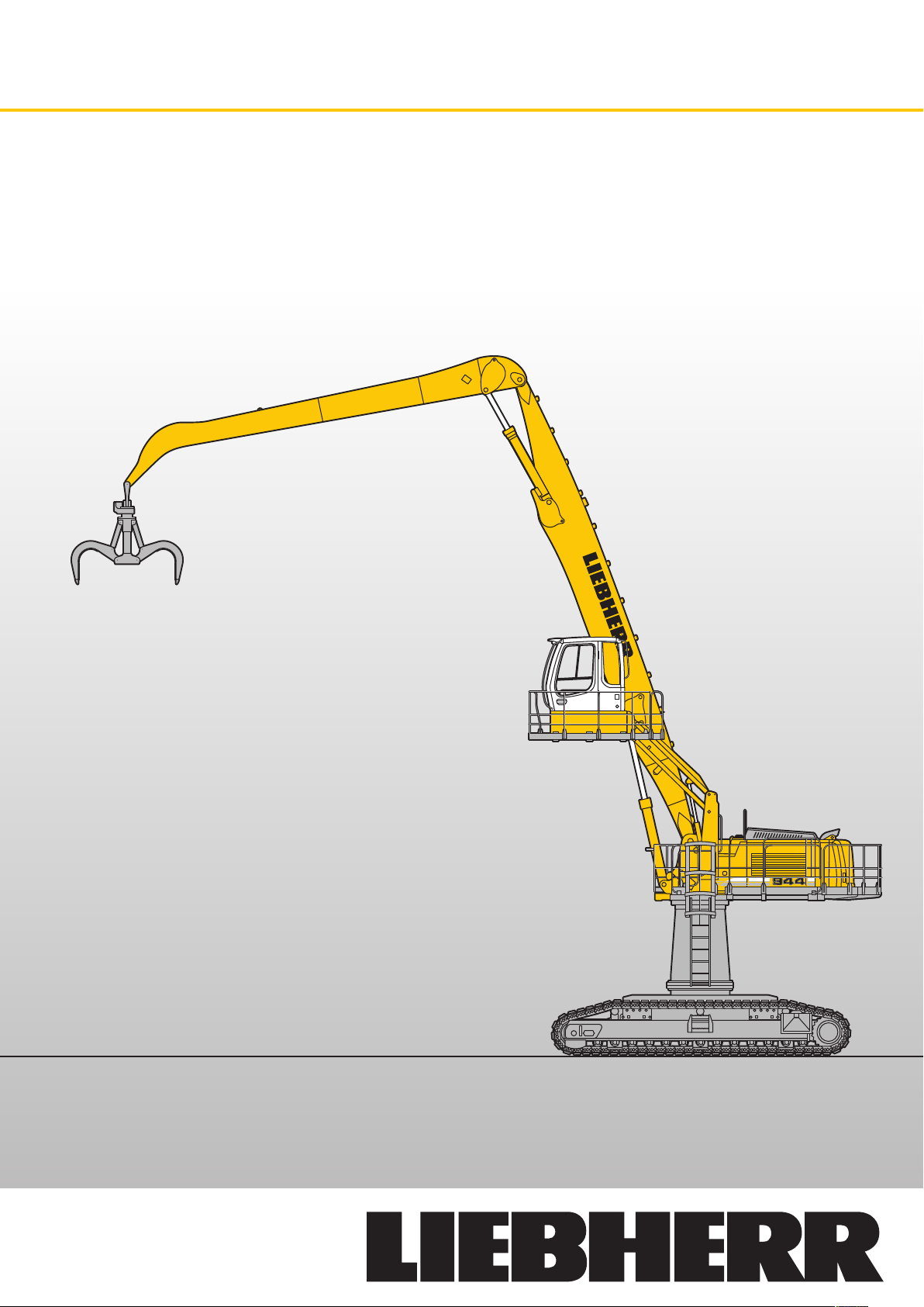
Machine for Industrial Applications
Operating Weight: 71,600 – 73,700 kg
Engine Output: 190 kW / 258 HP
Electric Motor Output: 200 kW / 272 HP
R 944 C
li tr on ic
`
High Rise
Page 2
Technical Data
Engine
Rating per ISO 9249
�������������������������������
Model
��������������������������������
Type
Bore/Stroke
Displacement
Engine operation
�����������������������������
Cooling
Air cleaner
Fuel tank
Standard
Electrical system
Voltage
Batteries
Starter
Alternator
�������������������������
���������������������������
���������������������������
�������������
������������������
����������������
�����������������
�����������������������
����������������������
������������������������
���������������������
190 kW (258 HP) at 1,800 RPM
Liebherr D 936 L
6 cylinder in-line
122/150 mm
10,5 l
4-stroke diesel
unit pump system
turbo-charged and after-cooled
reduced emissions
water-cooled and integrated motor oil cooler
dry-type air cleaner with pre-cleaner, primary and
safety elements, automatic dust discharge
660 l
sensor controlled engine idling
24 V
2 x 170 Ah/12 V
24 V/6,6 kW
three phase current 28 V/80 A
Hydraulic System
Hydraulic pump
for attachment and
travel drive
Max. flow
Max. pressure
Pump regulation
Hydraulic pump
for swing drive
Max. flow
Max. pressure
Hydraulic tank
Hydraulic system
Hydraulic oil filter
Hydraulic oil cooler
MODE selection
ECO
POWER
LIFT
FINE
RPM adjustment
Liebherr Tool Control
�������������������
���������������������
���������������
������������������
���������������
���������������������
���������������
��������������������
�����������������
�����������������
���������������
������������������
���������������������������
�����������������������
���������������������������
��������������������������
�����������������
������������
two Liebherr variable flow, swash plate pumps
2 x 303 l/min.
350 bar
electro-hydraulic with electronic engine speed
sensing regulation, pressure compensation, flow
compensation, automatic oil flow optimizer
reversible, variable flow, swash plate pump,
closed-loop circuit
205 l/min.
370 bar
460 l
710 l
2 full flow filters in return line with inte grated fine
filter area (5 µm)
cooler unit, consisting of radiator for engine
coolant with after-cooler core, for hydraulic fluid
with hydrostatically controlled fan drive
adjustment of machine performance and the
hydraulics via a mode selector to match applica-
tion
for especially economical and environ mentally
friendly operation
for maximum digging power and heavy duty jobs
for lifting
for precision work and lifting through very sensi-
tive movements
stepless adjustment of engine output via the rpm
at each selected mode
ten preadjustable pump flows and pressures for
add on tools (option)
Hydraulic Controls
Power distribution
Flow summation
Closed-loop circuit
Servo circuit
Attachment and swing
Travel
– speed pre-selection
Additional functions
���������������
������������
���������
�������������������������
�����
��������������
via monoblock control valve with integrated
safety valves
to boom and stick
for uppercarriage swing drive
proportional via joystick levers
– proportional via foot pedals or removable hand
levers
via foot pedals or joystick toggle switch
Swing Drive
����������������������������
Drive by
Transmission
Swing ring
Swing speed
Swing torque
Holding brake
Option
����������������������
�������������������������
����������������������
����������������������
���������������������
������������������������������
Operator’s Cab
���������������������������������
Cab
Operator’s seat
Joysticks
Monitoring
Heating system
Noise emission
ISO 6396
2000/14/EC
�������������������
���������������������������
�������������������������
�������������������
���������������������������
������������������������
Undercarriage
Version HR
��������������������������������
Drive
Transmission
Travel speed
Drawbar pull max.
Track components
Track rollers/Carrier rollers
Tracks
Track pads
Digging locks
Brake valves
����������������������
����������������������
����������������
���������������
������������������������������
�������������������������
���������������������
����������������������
Attachment
��������������������������������
Type
Hydraulic cylinders
�������������������������������
Pivots
Lubrication
VarioLiftPlus
���������������
������������������������
�����������������������
Liebherr swash plate motor
Liebherr compact planetary reduction gear
Liebherr, sealed single race ball bearing swing
ring, internal teeth
0 – 8 RPM stepless
125 kNm
wet multi-disc (spring applied, pressure released)
pedal controlled positioning brake
built from deep drawn components, resil iently
mounted, sound insulated, tinted windows, front
window stores overhead, door with sliding
window
shock absorbing suspension, adjustable to
operator’s weight, 6-way adjustable seat
integrated into adjustable seat consoles
menu driven query of current operating condi-
tions via the LCD display. Automatic monitoring,
display, warning (acoustical and optical signal)
and saving machine malfunction data, for exam-
ple, engine overheating, low engine oil pressure
or low hydraulic oil level
standard air conditioning, combined cooler/
heater, additional dust filter in fresh air/recircu-
lated
LpA (inside cab) = 75 dB(A)
LWA (surround noise) = 105 dB(A)
Liebherr swash plate motors with inte grated
brake valves on both sides
Liebherr planetary reduction gears
low range – 3.0 km/h
high range – 3.8 km/h
320 kN
D 7 G, maintenance-free
�����
13/3
sealed and greased
flat pad
wet multi-discs (spring applied, pressure
released)
integrated into travel motor
high-strength steel plates at highly-stressed
points for the toughest requirements. Complex
and stable mountings of attachment and cylin-
ders. Unrivalled strength, even at high loads
Liebherr cylinders with special seal system.
Shock absorption
sealed, low maintenance
Liebherr semi-automatic central lubrication
system
variable boom mounting positions for optimized
lift capacities
2 R 944 C Litronic High Rise
Page 3
Version with Electric Motor
Electric Motor
�������������������������������
Motor
Power rating
(as per CEI 34-1)
Rated voltage
Number of poles
Design type
Standard degree of protection
Insulation
Starter star/delta
Heat protection for windings
Heat protection for bearings
Anti-condensation heating system resistors
�����������������
���������������������
������������������
������������������������
��������������������������
asynchronous three-phase, cage rotor enclosed
in cast iron envelope, special Liebherr design
200 kW (272 HP) at 1,485 RPM
400 V – 50 Hz *
4
horizontal axle B35
axle height 315 mm
painting: RAL 7031
��
IP55 – steel flange FF600
class F, thermal loading: Class B,
ambient temperature 40 °C
Electric System
The 400 V electrical cabinet provides a degree of protection to IP55.
This houses the following components:
– Main motorised isolator, controlled from the cab
– Star/delta starter for motor
– Outlets for supplying auxiliary elements: heating, climate control
– Various heat protection devices
– Resistors for controlling the temperature of the cabinet
– Booster pump integrated in the cabinet: Cabinet air filtered (option)
– Transformers – rectifier for 24 V control circuit
– Motor protection attachment
– Auxiliary batteries: 2 x 135 Ah/12 V: secured functions: lighting for excavator/
attachment position (option)
Hydraulic System
Hydraulic pump
for attachment and
travel drive
Max. flow
Max. pressure
Pump regulation
Hydraulic pump
for swing drive
Max. flow
Max. pressure
Hydraulic tank
Hydraulic system
Hydraulic oil filter
Hydraulic oil cooler
Liebherr Tool Control
�������������������
���������������������
���������������
������������������
���������������
���������������������
���������������
��������������������
�����������������
�����������������
���������������
������������
two Liebherr variable flow, swash plate pumps
2 x 305 l/min.
350 bar
electro-hydraulic with electronic engine speed
sensing regulation, pressure compensation, automatic oil flow optimizer
reversible, variable flow, swash plate pump,
closed-loop circuit
205 l/min.
370 bar
460 l
710 l
2 full flow filters in return line with inte grated fine
filter area (5 µm)
radiator equipped with hydrostatic drive fan for
cooling the hydraulic oil and climate control
condenser
ten preadjustable pump flows and pressures for
add on tools (option)
Hydraulic Controls
Power distribution
Flow summation
Closed-loop circuit
Servo circuit
Attachment and swing
Travel
– speed pre-selection
Additional functions
���������������
������������
���������
�������������������������
�����
��������������
via monoblock control valve with integrated
safety valves
to boom and stick
for uppercarriage swing drive
proportional via joystick levers
– proportional via foot pedals or removable hand
levers
via foot pedals or joystick toggle switch
Swing Drive
����������������������������
Drive by
Transmission
Swing ring
Swing speed
Swing torque
Holding brake
Option
����������������������
�������������������������
����������������������
����������������������
���������������������
������������������������������
Operator’s Cab
���������������������������������
Cab
Operator’s seat
Joysticks
Monitoring
Heating system
�������������������
���������������������������
�������������������������
�������������������
Undercarriage
Version HR
��������������������������������
Drive
Transmission
Travel speed
Drawbar pull max.
Track components
Track rollers/Carrier rollers
Tracks
Track pads
Digging locks
Brake valves
����������������������
����������������������
����������������
���������������
������������������������������
�������������������������
���������������������
����������������������
Attachment
��������������������������������
Type
Hydraulic cylinders
�������������������������������
Pivots
Lubrication
VarioLiftPlus
���������������
������������������������
�����������������������
Liebherr hydraulic motor with integrated brake
valves
Liebherr compact planetary reduction gear
Liebherr, sealed single race ball bearing swing
ring, internal teeth
0 – 7.9 RPM stepless
119 kNm
wet multi-disc (spring applied, pressure released)
pedal controlled positioning brake
built from deep drawn components, resil iently
mounted, sound insulated, tinted windows, front
window stores overhead, door with sliding
window
shock absorbing suspension, adjustable to
operator’s weight, 6-way adjustable seat
integrated into adjustable seat consoles
menu driven digital display of current operating
conditions. Automatic monitoring, display,
warning (audible and visual signal) and saving
of machine malfunction data, such as overheating
of windings, motor bearings, or low hydraulic oil
level
standard air conditioning, combined cooler/
heater, additional dust filter in fresh air/recircu-
lated
Liebherr hydraulic motor with integrated brake
valves on both sides
Liebherr planetary reduction gears
low range – 3.0 km/h
high range – 3.8 km/h
320 kN
D 7 G, maintenance-free
�����
13/3
sealed and greased
flat pad
wet multi-discs (spring applied, pressure
released)
integrated into travel motor
high-strength steel plates at highly-stressed
points for the toughest requirements. Complex
and stable mountings of attachment and cylin-
ders. Unrivalled strength, even at high loads
Liebherr cylinders with special seal system.
Shock absorption
sealed, low maintenance
Liebherr semi-automatic central lubrication
system
variable boom mounting positions for optimized
lift capacities
* Other voltages and frequencies possible on request.
R 944 C Litronic High Rise 3
Page 4
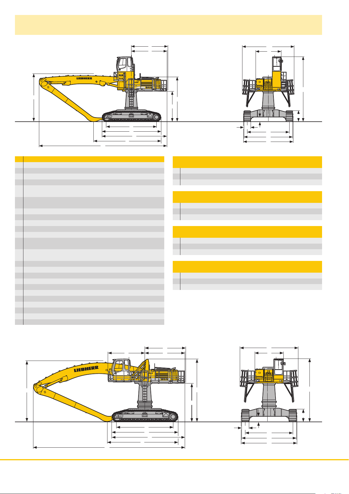
Dimensions
E
D
W
L
U
Z
X
V
mm
A 6,150
A1 3,050
C with Rigid Cab Elevation 2 m 7,700
C* with Rigid Cab Elevation 2 m 8,160
C with Hydraulic Cab Elevation Parallelogram
+ Intermediate Piece 0,5 m 6,170
C* with Hydraulic Cab Elevation Parallelogram
+ Intermediate Piece 0,5 m 6,630
D 4,250
E 4,350
F 4,100
H with Rigid Cab Elevation 2 m 5,300
H* with Rigid Cab Elevation 2 m 5,760
H with Hydraulic Cab Elevation Parallelogram
+ Intermediate Piece 0,5 m 6,170
H* with Hydraulic Cab Elevation Parallelogram
+ Intermediate Piece 0,5 m 6,630
K 3,600
K* 4,060
L 6,000
P 1,280
Q 555
S 5,000
U 7,000
Z 7,750
N 750
B 5,830
G 5,860
E = Tail radius
* = with Elevation
A1
A
C
H
K
Q
N
S
B
G
P
Industrial-Type Straight Boom 9.50 m
and Industrial Stick m 7.30 7.30* 8.80 8.80*
V mm 8,850 8,350 7,000 7,300
W mm 5,700 6,160 5,700 6,160
X mm 14,300 14,300 14,300 14,300
Industrial-Type Straight Boom 10.50 m
and Industrial Stick m 8.80 8.80* 9.50 9.50*
V mm 8,000 8,300 7,150 7,400
W mm 5,700 6,160 5,700 6,160
X mm 15,250 15,250 15,250 15,250
Industrial-Type Straight Boom 11.50 m
and Industrial Stick m 9.50 9.50* 12.00 12.00*
V mm 8,150 8,450 ** **
W mm 5,700 6,160 5,700 6,160
X mm 16,250 16,250 16,250 16,250
Industrial-Type Gooseneck Boom 11.50 m
and Industrial Stick m 9.50 9.50* 12.00 12.00*
V mm 7,400 7,500 ** **
W mm 5,950 6,400 5,950 6,400
X mm 16,100 16,100 16,100 16,100
** = without Stick
W
4 R 944 C Litronic High Rise
E
F
L
U
V
X
D
H
K
N
Z
A1
A
C
Q
S
B
G
P
Page 5

VarioLiftPlus
Variable Boom Mounting Positions for Optimized Lift Capacities
with the same working range with a different working range
Hole A
Hole B
Hole 3
Hole 2
Version 2A
2A
2A
3B
3B
3A
Kinematic variant 2A:
Increased lift capacities above ground level
Kinematic variant 3B:
Increased lift capacities below ground level
and when working at large outreach
with a different working range
Kinematic variant 3A:
Altered range curve with additional reach
depth, e.g. for unloading from ships
Hole C
Hole D
Hole 3
Hole 2
Version 3D
3D
3D
Kinematic variant 3D:
Increased lift capacities below ground level
and when working at large outreach
3C
Kinematic variant 3C:
Altered range curve with additional reach
depth, e.g. for unloading from ships
R 944 C Litronic High Rise 5
Page 6

Industrial Attachment
with Industrial-Type Straight Boom 9.50 m
ft m
70
60
50
40
30
20
10
0
-10
-20
22
20
18
16
14
12
10
8
6
4
2
0
-2
-4
-6
-8
1
3
2
4
024 68101214161820
0mft102030405060
Kinematic variant 2A
1 with industrial stick 7.30 m
2 with industrial stick 8.80 m
3 with industrial stick 7.30 m and grapple model 70 C
4 with industrial stick 8.80 m and grapple model 70 C
Operating Weight
and Ground Pressure
Operating weight includes basic machine with hydraulic cab elevation
parallelogram + intermediate piece 0.5 m, counterweight 11.0 t, industrial-type straight boom 9.50 m, industrial stick 7.30 m and grapple
model 70 C with 5 semi-closed tines 1.10 m
Undercarriage HR
Pad width mm 750
Weight kg 71,600
Ground pressure kg/cm
Operating weight includes basic machine with hydraulic cab elevation
parallelogram + intermediate piece 0.5 m, counterweight 11.0 t, industrial-type straight boom 9.50 m, industrial stick 8.80 m and grapple
model 70 C with 5 semi-closed tines 1.10 m
Undercarriage HR
Pad width mm 750
Weight kg 71,900
Ground pressure kg/cm
3
.
2
0.80
3
.
2
0.80
Attachment Envelope
6 R 944 C Litronic High Rise
Page 7
Lift Capacities
with Industrial-Type Straight Boom 9.50 m
Industrial Stick 7.30 m (Variant 2A)
4.5 m 6.0 m 7.5 m 9.0 m 10.5 m 12.0 m 13.5 m 15.0 m 16.5 m 18.0 m 19.5 m 21.0 m 22.5 m
Under m carriage m
25.5 HR
24.0 HR
22.5 HR
21.0 HR
19.5 HR
18.0 HR
16.5 HR
15.0 HR
13.5 HR
12.0 HR
10.5 HR
9.0 HR
7.5 HR
6.0 HR
4.5 HR
3.0 HR
1.5 HR
0 HR
– 1.5 HR
– 3.0 HR
– 4.5 HR
– 6.0 HR
– 7.5 HR
– 9.0 HR
11.6* 11.6* 10.0* 10.0*
11.5* 11.5* 9.3* 9.3* 8.3* 8.3*
12.4* 12.4* 11.2* 11.2* 9.2* 9.2* 7.4* 7.4*
12.9* 12.9* 11.5* 11.5* 10.3* 10.3* 8.7* 8.7* 6.9* 6.9*
13.0* 13.0* 11.5* 11.5* 10.3* 10.3* 9.3* 9.3* 7.5* 7.5* 6.6* 6.6*
13.2* 13.2* 11.6* 11.6* 10.3* 10.3* 9.3* 9.3* 8.3* 8.3* 6.4* 6.4*
13.6* 13.6* 11.8* 11.8* 10.4* 10.4* 9.3* 9.3* 8.3* 8.3* 7.3* 7.3* 6.4* 6.4*
15.4* 15.4* 14.2* 14.2* 12.2* 12.2* 10.6* 10.6* 9.4* 9.4* 8.3* 8.3* 7.3* 7.3* 6.3* 6.3*
17.9* 17.9* 18.2* 18.2* 14.8* 14.8* 12.5* 12.5* 10.8* 10.8* 9.4* 9.4* 8.3* 8.3* 7.2* 7.2* 6.2* 6.2*
26.0* 26.0* 19.3* 19.3* 15.4* 15.4* 12.8* 12.8* 10.9* 10.9* 9.4* 9.4* 8.2* 8.2* 7.0* 7.0* 5.8* 5.8*
9.7* 9.7* 19.8* 19.8* 15.6* 15.6* 12.8* 12.8* 10.8* 10.8* 9.3* 9.3* 8.0* 8.0* 6.7* 6.7* 5.4* 5.4*
6.3* 6.3* 19.3* 19.3* 15.3* 15.3* 12.6* 12.6* 10.6* 10.6* 9.0* 9.0* 7.6* 7.6* 6.3* 6.3* 4.9* 4.9*
6.5* 6.5* 14.3* 14.3* 14.5* 14.5* 12.0* 12.0* 10.0* 10.0* 8.4* 8.4* 7.0* 7.0* 5.6* 5.6* 4.3* 4.3*
7.7* 7.7* 13.6* 13.6* 13.0* 13.0* 10.9* 10.9* 9.1* 9.1* 7.6* 7.6* 6.2* 6.2* 4.5* 4.5* 4.4* 4.4*
12.5* 12.5* 10.9* 10.9* 9.3* 9.3* 7.8* 7.8* 6.3* 6.3* 5.1* 5.1*
6.91
9.50
11.31
12.69
13.78
14.62
15.28
15.76
16.09
16.27
16.31
16.22
15.98
15.11
13.31
Industrial Stick 8.80 m (Variant 2A)
4.5 m 6.0 m 7.5 m 9.0 m 10.5 m 12.0 m 13.5 m 15.0 m 16.5 m 18.0 m 19.5 m 21.0 m 22.5 m
Under m carriage m
25.5 HR
24.0 HR
22.5 HR
21.0 HR
19.5 HR
18.0 HR
16.5 HR
15.0 HR
13.5 HR
12.0 HR
10.5 HR
9.0 HR
7.5 HR
6.0 HR
4.5 HR
3.0 HR
1.5 HR
0 HR
– 1.5 HR
– 3.0 HR
– 4.5 HR
– 6.0 HR
– 7.5 HR
– 9.0 HR
Height Can be slewed through 360° In longitudinal position of undercarriage Max. reach * Limited by hydr. capacity
The lift capacities are stated in metric tonnes (t) on the lifting gear’s stick tip, and can be lifted 360° on firm, level supporting surface. Capacities
are valid for 750 mm track flat pads. Indicated loads are based on ISO 10567 standard and do not exceed 75 % of tipping or 87 % of hydraulic
capacity (indicated via *). Lifting capacity of the excavator is limited by machine stability, hydraulic capacity and maximum permissible load of the
load hook.
According to European Standard, EN 474-5: In the European Union excavators have to be equipped with an overload warning device, a load diagram and automatic check valves on the hoist cylinders, when they are used for lifting operations which require the use of lifting accessories.
10.3* 10.3* 8.6* 8.6*
10.0* 10.0* 8.4* 8.4* 7.0* 7.0*
9.6* 9.6* 8.3* 8.3* 6.2* 6.2*
10.2* 10.2* 9.3* 9.3* 8.0* 8.0* 5.7* 5.7*
10.5* 10.5* 9.6* 9.6* 8.8* 8.8* 7.4* 7.4* 5.4* 5.4*
10.6* 10.6* 9.6* 9.6* 8.7* 8.7* 8.0* 8.0* 6.4* 6.4* 5.2* 5.2*
10.7* 10.7* 9.6* 9.6* 8.7* 8.7* 8.0* 8.0* 7.2* 7.2* 5.1* 5.1*
11.0* 11.0* 9.8* 9.8* 8.8* 8.8* 8.0* 8.0* 7.2* 7.2* 6.0* 6.0* 5.0* 5.0*
11.7* 11.7* 11.3* 11.3* 10.0* 10.0* 8.9* 8.9* 8.0* 8.0* 7.2* 7.2* 6.3* 6.3* 5.0* 5.0*
11.5* 11.5* 13.5* 13.5* 11.8* 11.8* 10.3* 10.3* 9.1* 9.1* 8.1* 8.1* 7.2* 7.2* 6.3* 6.3* 5.0* 5.0*
13.4* 13.4* 16.7* 16.7* 14.5* 14.5* 12.2* 12.2* 10.5* 10.5* 9.2* 9.2* 8.1* 8.1* 7.1* 7.1* 6.1* 6.1* 5.1* 5.1*
25.6* 25.6* 19.0* 19.0* 15.1* 15.1* 12.5* 12.5* 10.6* 10.6* 9.2* 9.2* 8.0* 8.0* 6.9* 6.9* 5.9* 5.9* 4.7* 4.7*
11.5* 11.5* 19.4* 19.4* 15.3* 15.3* 12.6* 12.6* 10.6* 10.6* 9.1* 9.1* 7.8* 7.8* 6.7* 6.7* 5.5* 5.5* 4.4* 4.4*
7.9* 7.9* 18.9* 18.9* 15.0* 15.0* 12.3* 12.3* 10.3* 10.3* 8.8* 8.8* 7.5* 7.5* 6.3* 6.3* 5.0* 5.0* 3.9* 3.9*
7.8* 7.8* 15.3* 15.3* 14.1* 14.1* 11.6* 11.6* 9.7* 9.7* 8.2* 8.2* 6.9* 6.9* 5.6* 5.6* 4.2* 4.2* 3.6* 3.6*
8.5* 8.5* 14.3* 14.3* 12.7* 12.7* 10.5* 10.5* 8.8* 8.8* 7.4* 7.4* 6.1* 6.1* 4.7* 4.7* 3.9* 3.9*
12.4* 12.4* 10.6* 10.6* 8.9* 8.9* 7.5* 7.5* 6.1* 6.1* 4.8* 4.8* 4.6* 4.6*
7.15
9.90
11.85
13.34
14.53
15.48
16.24
16.83
17.27
17.57
17.74
17.78
17.69
17.47
16.98
15.76
13.70
R 944 C Litronic High Rise 7
Page 8

Industrial Attachment
with Industrial-Type Straight Boom 9.50 m
ft m
70
60
50
40
30
20
10
0
-10
-20
22
20
18
16
14
12
Attachment Envelope
Kinematic variants 3A/3B
1 with industrial stick 7.30 m (3B)
2 with industrial stick 7.30 m and grapple model 70 C (3B)
3 with industrial stick 7.30 m (3A)
4 with industrial stick 7.30 m and grapple model 70 C (3A)
Operating Weight
10
8
6
4
2
0
-2
-4
-6
-8
1
3
2
4
024 681012141618
and Ground Pressure
Operating weight includes basic machine with hydraulic cab elevation
parallelogram + intermediate piece 0.5 m, counterweight 11.0 t, industrial-type straight boom 9.50 m, industrial stick 7.30 m and grapple
model 70 C with 5 semi-closed tines 1.10 m
Undercarriage HR
Pad width mm 750
Weight kg 71,600
Ground pressure kg/cm
3
.
2
0.80
ft m
70
60
50
40
30
20
10
0
-10
-20
-30
0mft102030405060
Attachment Envelope
22
20
18
16
14
12
10
8
6
4
2
0
-2
-4
-6
-8
1
3
2
4
024 681012141620 18
Kinematic variants 3A/3B
1 with industrial stick 8.80 m (3B)
2 with industrial stick 8.80 m and grapple model 70 C (3B)
3 with industrial stick 8.80 m (3A)
4 with industrial stick 8.80 m and grapple model 70 C (3A)
Operating Weight
and Ground Pressure
Operating weight includes basic machine with hydraulic cab elevation
parallelogram + intermediate piece 0.5 m, counterweight 11.0 t, industrial-type straight boom 9.50 m, industrial stick 8.80 m and grapple
model 70 C with 5 semi-closed tines 1.10 m
Undercarriage HR
Pad width mm 750
Weight kg 71,900
Ground pressure kg/cm
3
.
2
0.80
8 R 944 C Litronic High Rise
0mft102030405060
Page 9

Lift Capacities
with Industrial-Type Straight Boom 9.50 m
Industrial Stick 7.30 m (Variant 3A)
4.5 m 6.0 m 7.5 m 9.0 m 10.5 m 12.0 m 13.5 m 15.0 m 16.5 m 18.0 m 19.5 m 21.0 m 22.5 m
Under m carriage m
25.5 HR
24.0 HR
22.5 HR
21.0 HR
19.5 HR
18.0 HR
16.5 HR
15.0 HR
13.5 HR
12.0 HR
10.5 HR
9.0 HR
7.5 HR
6.0 HR
4.5 HR
3.0 HR
1.5 HR
0 HR
– 1.5 HR
– 3.0 HR
– 4.5 HR
– 6.0 HR
– 7.5 HR
– 9.0 HR
8.1* 8.1*
9.7* 9.7* 7.3* 7.3*
9.5* 9.5* 8.9* 8.9* 6.9* 6.9*
9.4* 9.4* 8.8* 8.8* 8.2* 8.2* 6.6* 6.6*
9.6* 9.6* 8.9* 8.9* 8.3* 8.3* 6.4* 6.4*
9.8* 9.8* 9.0* 9.0* 8.3* 8.3* 7.8* 7.8* 6.4* 6.4*
11.4* 11.4* 10.2* 10.2* 9.2* 9.2* 8.5* 8.5* 7.8* 7.8* 6.3* 6.3*
17.0* 17.0* 14.0* 14.0* 12.0* 12.0* 10.6* 10.6* 9.5* 9.5* 8.6* 8.6* 7.8* 7.8* 6.4* 6.4*
25.8* 25.8* 19.0* 19.0* 15.2* 15.2* 12.7* 12.7* 11.0* 11.0* 9.7* 9.7* 8.7* 8.7* 7.9* 7.9* 6.5* 6.5*
7.5* 7.5* 20.5* 20.5* 16.1* 16.1* 13.3* 13.3* 11.4* 11.4* 9.9* 9.9* 8.8* 8.8* 7.8* 7.8* 6.7* 6.7*
5.6* 5.6* 16.2* 16.2* 16.6* 16.6* 13.7* 13.7* 11.6* 11.6* 10.0* 10.0* 8.8* 8.8* 7.7* 7.7* 6.6* 6.6*
6.2* 6.2* 13.0* 13.0* 16.7* 16.7* 13.7* 13.7* 11.6* 11.6* 9.9* 9.9* 8.6* 8.6* 7.4* 7.4* 6.3* 6.3*
7.5* 7.5* 12.9* 12.9* 16.1* 16.1* 13.3* 13.3* 11.3* 11.3* 9.6* 9.6* 8.2* 8.2* 6.8* 6.8* 6.0* 6.0*
9.0* 9.0* 13.8* 13.8* 15.0* 15.0* 12.5* 12.5* 10.6* 10.6* 8.9* 8.9* 7.5* 7.5* 5.8* 5.8*
13.2* 13.2* 11.2* 11.2* 9.4* 9.4* 7.8* 7.8* 6.9* 6.9*
9.93
11.67
13.00
14.05
14.87
15.49
15.95
16.26
16.43
16.45
16.33
16.08
15.67
14.92
12.90
Industrial Stick 8.80 m (Variant 3A)
4.5 m 6.0 m 7.5 m 9.0 m 10.5 m 12.0 m 13.5 m 15.0 m 16.5 m 18.0 m 19.5 m 21.0 m 22.5 m
Under m carriage m
25.5 HR
24.0 HR
22.5 HR
21.0 HR
19.5 HR
18.0 HR
16.5 HR
15.0 HR
13.5 HR
12.0 HR
10.5 HR
9.0 HR
7.5 HR
6.0 HR
4.5 HR
3.0 HR
1.5 HR
0 HR
– 1.5 HR
– 3.0 HR
– 4.5 HR
– 6.0 HR
– 7.5 HR
– 9.0 HR
Height Can be slewed through 360° In longitudinal position of undercarriage Max. reach * Limited by hydr. capacity
The lift capacities are stated in metric tonnes (t) on the lifting gear’s stick tip, and can be lifted 360° on firm, level supporting surface. Capacities
are valid for 750 mm track flat pads. Indicated loads are based on ISO 10567 standard and do not exceed 75 % of tipping or 87 % of hydraulic
capacity (indicated via *). Lifting capacity of the excavator is limited by machine stability, hydraulic capacity and maximum permissible load of the
load hook.
According to European Standard, EN 474-5: In the European Union excavators have to be equipped with an overload warning device, a load diagram and automatic check valves on the hoist cylinders, when they are used for lifting operations which require the use of lifting accessories.
6.9* 6.9*
6.6* 6.6* 6.1* 6.1*
8.2* 8.2* 6.1* 6.1* 5.7* 5.7*
8.0* 8.0* 7.6* 7.6* 5.4* 5.4*
8.0* 8.0* 7.6* 7.6* 6.8* 6.8* 5.2* 5.2*
8.0* 8.0* 7.6* 7.6* 7.2* 7.2* 5.1* 5.1*
8.2* 8.2* 7.7* 7.7* 7.2* 7.2* 6.5* 6.5* 5.0* 5.0*
9.2* 9.2* 8.5* 8.5* 7.9* 7.9* 7.3* 7.3* 6.8* 6.8* 5.0* 5.0*
10.9* 10.9* 9.7* 9.7* 8.8* 8.8* 8.0* 8.0* 7.4* 7.4* 6.8* 6.8* 5.0* 5.0*
13.6* 13.6* 11.7* 11.7* 10.2* 10.2* 9.1* 9.1* 8.3* 8.3* 7.5* 7.5* 6.8* 6.8* 5.1* 5.1*
25.4* 25.4* 18.6* 18.6* 14.8* 14.8* 12.4* 12.4* 10.7* 10.7* 9.4* 9.4* 8.4* 8.4* 7.6* 7.6* 6.8* 6.8* 5.2* 5.2*
9.2* 9.2* 20.2* 20.2* 15.8* 15.8* 13.0* 13.0* 11.1* 11.1* 9.7* 9.7* 8.5* 8.5* 7.6* 7.6* 6.7* 6.7* 5.4* 5.4*
7.2* 7.2* 17.5* 17.5* 16.3* 16.3* 13.4* 13.4* 11.3* 11.3* 9.8* 9.8* 8.5* 8.5* 7.5* 7.5* 6.5* 6.5* 5.6* 5.6*
7.4* 7.4* 14.1* 14.1* 16.3* 16.3* 13.4* 13.4* 11.3* 11.3* 9.7* 9.7* 8.4* 8.4* 7.3* 7.3* 6.1* 6.1* 5.4* 5.4*
8.3* 8.3* 13.6* 13.6* 15.8* 15.8* 13.0* 13.0* 11.0* 11.0* 9.4* 9.4* 8.0* 8.0* 6.8* 6.8* 5.3* 5.3* 5.1* 5.1*
9.4* 9.4* 14.1* 14.1* 14.7* 14.7* 12.2* 12.2* 10.3* 10.3* 8.7* 8.7* 7.3* 7.3* 5.9* 5.9* 5.3* 5.3*
12.9* 12.9* 10.9* 10.9* 9.1* 9.1* 7.6* 7.6* 6.4* 6.4*
10.35
12.22
13.67
14.82
15.74
16.47
17.04
17.46
17.74
17.89
17.92
17.81
17.57
17.20
16.69
15.53
13.24
R 944 C Litronic High Rise 9
Page 10

Lift Capacities
with Industrial-Type Straight Boom 9.50 m
Industrial Stick 7.30 m (Variant 3B)
4.5 m 6.0 m 7.5 m 9.0 m 10.5 m 12.0 m 13.5 m 15.0 m 16.5 m 18.0 m 19.5 m 21.0 m 22.5 m
Under m carriage m
25.5 HR
24.0 HR
22.5 HR
21.0 HR
19.5 HR
18.0 HR
16.5 HR
15.0 HR
13.5 HR
12.0 HR
10.5 HR
9.0 HR
7.5 HR
6.0 HR
4.5 HR
3.0 HR
1.5 HR
0 HR
– 1.5 HR
– 3.0 HR
– 4.5 HR
– 6.0 HR
– 7.5 HR
– 9.0 HR
12.1* 12.1* 9.6* 9.6*
11.0* 11.0* 10.0* 10.0* 8.1* 8.1*
10.3* 10.3* 9.6* 9.6* 9.1* 9.1* 7.3* 7.3*
9.4* 9.4* 8.8* 8.8* 8.4* 8.4* 6.9* 6.9*
9.3* 9.3* 8.8* 8.8* 8.3* 8.3* 7.9* 7.9* 6.6* 6.6*
10.4* 10.4* 9.6* 9.6* 8.9* 8.9* 8.3* 8.3* 7.9* 7.9* 6.4* 6.4*
11.0* 11.0* 10.0* 10.0* 9.2* 9.2* 8.5* 8.5* 7.9* 7.9* 7.5* 7.5* 6.4* 6.4*
13.8* 13.8* 11.9* 11.9* 10.6* 10.6* 9.5* 9.5* 8.7* 8.7* 8.1* 8.1* 7.5* 7.5* 6.3* 6.3*
19.4* 19.4* 15.8* 15.8* 13.1* 13.1* 11.3* 11.3* 10.0* 10.0* 9.0* 9.0* 8.3* 8.3* 7.6* 7.6* 6.4* 6.4*
24.3* 24.3* 17.9* 17.9* 14.3* 14.3* 12.1* 12.1* 10.5* 10.5* 9.4* 9.4* 8.5* 8.5* 7.7* 7.7* 6.5* 6.5*
7.5* 7.5* 19.7* 19.7* 15.4* 15.4* 12.8* 12.8* 11.0* 11.0* 9.6* 9.6* 8.6* 8.6* 7.8* 7.8* 6.7* 6.7*
5.6* 5.6* 16.2* 16.2* 16.2* 16.2* 13.3* 13.3* 11.3* 11.3* 9.8* 9.8* 8.7* 8.7* 7.7* 7.7* 6.8* 6.8*
6.2* 6.2* 13.0* 13.0* 16.5* 16.5* 13.6* 13.6* 11.5* 11.5* 9.9* 9.9* 8.7* 8.7* 7.6* 7.6* 6.7* 6.7*
7.5* 7.5* 12.9* 12.9* 16.4* 16.4* 13.5* 13.5* 11.4* 11.4* 9.8* 9.8* 8.4* 8.4* 7.2* 7.2* 7.1* 7.1*
15.7* 15.7* 13.0* 13.0* 11.0* 11.0* 9.4* 9.4* 8.3* 8.3*
7.49
9.93
11.67
13.00
14.05
14.87
15.49
15.95
16.26
16.43
16.45
16.33
16.08
15.06
13.07
Industrial Stick 8.80 m (Variant 3B)
4.5 m 6.0 m 7.5 m 9.0 m 10.5 m 12.0 m 13.5 m 15.0 m 16.5 m 18.0 m 19.5 m 21.0 m 22.5 m
Under m carriage m
25.5 HR
24.0 HR
22.5 HR
21.0 HR
19.5 HR
18.0 HR
16.5 HR
15.0 HR
13.5 HR
12.0 HR
10.5 HR
9.0 HR
7.5 HR
6.0 HR
4.5 HR
3.0 HR
1.5 HR
0 HR
– 1.5 HR
– 3.0 HR
– 4.5 HR
– 6.0 HR
– 7.5 HR
– 9.0 HR
Height Can be slewed through 360° In longitudinal position of undercarriage Max. reach * Limited by hydr. capacity
The lift capacities are stated in metric tonnes (t) on the lifting gear’s stick tip, and can be lifted 360° on firm, level supporting surface. Capacities
are valid for 750 mm track flat pads. Indicated loads are based on ISO 10567 standard and do not exceed 75 % of tipping or 87 % of hydraulic
capacity (indicated via *). Lifting capacity of the excavator is limited by machine stability, hydraulic capacity and maximum permissible load of the
load hook.
According to European Standard, EN 474-5: In the European Union excavators have to be equipped with an overload warning device, a load diagram and automatic check valves on the hoist cylinders, when they are used for lifting operations which require the use of lifting accessories.
8.7* 8.7* 8.3* 8.3*
8.8* 8.8* 6.9* 6.9*
8.7* 8.7* 8.3* 8.3* 6.6* 6.6* 6.1* 6.1*
8.3* 8.3* 7.9* 7.9* 7.6* 7.6* 6.1* 6.1* 5.7* 5.7*
7.7* 7.7* 7.4* 7.4* 7.2* 7.2* 5.4* 5.4*
7.7* 7.7* 7.4* 7.4* 7.1* 7.1* 6.8* 6.8* 5.2* 5.2*
8.3* 8.3* 7.9* 7.9* 7.5* 7.5* 7.1* 7.1* 6.8* 6.8* 5.1* 5.1*
8.7* 8.7* 8.1* 8.1* 7.7* 7.7* 7.2* 7.2* 6.9* 6.9* 6.5* 6.5* 5.0* 5.0*
10.2* 10.2* 9.3* 9.3* 8.6* 8.6* 7.9* 7.9* 7.4* 7.4* 7.0* 7.0* 6.6* 6.6* 5.0* 5.0*
11.7* 11.7* 11.4* 11.4* 10.1* 10.1* 9.1* 9.1* 8.3* 8.3* 7.6* 7.6* 7.1* 7.1* 6.6* 6.6* 5.0* 5.0*
14.8* 14.8* 15.3* 15.3* 12.7* 12.7* 10.9* 10.9* 9.6* 9.6* 8.7* 8.7* 7.9* 7.9* 7.2* 7.2* 6.7* 6.7* 5.1* 5.1*
23.9* 23.9* 17.5* 17.5* 14.0* 14.0* 11.7* 11.7* 10.2* 10.2* 9.0* 9.0* 8.1* 8.1* 7.4* 7.4* 6.7* 6.7* 5.2* 5.2*
9.2* 9.2* 19.3* 19.3* 15.1* 15.1* 12.5* 12.5* 10.7* 10.7* 9.3* 9.3* 8.3* 8.3* 7.5* 7.5* 6.7* 6.7* 5.4* 5.4*
7.2* 7.2* 17.5* 17.5* 15.9* 15.9* 13.0* 13.0* 11.0* 11.0* 9.6* 9.6* 8.4* 8.4* 7.5* 7.5* 6.6* 6.6* 5.7* 5.7*
7.4* 7.4* 14.1* 14.1* 16.2* 16.2* 13.2* 13.2* 11.2* 11.2* 9.6* 9.6* 8.4* 8.4* 7.4* 7.4* 6.4* 6.4* 6.0* 6.0*
8.3* 8.3* 13.6* 13.6* 16.0* 16.0* 13.2* 13.2* 11.1* 11.1* 9.5* 9.5* 8.2* 8.2* 7.1* 7.1* 6.6* 6.6*
15.3* 15.3* 12.7* 12.7* 10.7* 10.7* 9.1* 9.1* 7.8* 7.8*
7.75
10.35
12.22
13.67
14.82
15.74
16.47
17.04
17.46
17.74
17.89
17.92
17.81
17.57
16.98
15.67
13.41
10 R 944 C Litronic High Rise
Page 11

Industrial Attachment
with Industrial-Type Straight Boom 10.50 m
ft m
70
60
50
40
30
20
10
0
-10
-20
24
22
20
18
16
14
12
10
8
6
4
2
Attachment Envelope
Kinematic variant 2A
1 with industrial stick 8.80 m
2 with industrial stick 9.50 m
3 with industrial stick 8.80 m and grapple model 70 C
4 with industrial stick 9.50 m and grapple model 70 C
Operating Weight
and Ground Pressure
Operating weight includes basic machine with hydraulic cab elevation
parallelogram + intermediate piece 0.5 m, counterweight 11.0 t, industrial-type straight boom 10.50 m, industrial stick 8.80 m and grapple
model 70 C with 5 semi-closed tines 1.10 m
Undercarriage HR
3
.
Pad width mm 750
0
-2
-4
-6
-8
1
3
2
4
024 68101214161820
0mft10203040506070
Weight kg 72,300
Ground pressure kg/cm
2
0.80
Operating weight includes basic machine with hydraulic cab elevation
parallelogram + intermediate piece 0.5 m, counterweight 11.0 t, industrial-type straight boom 10.50 m, industrial stick 9.50 m and grapple
model 70 C with 5 semi-closed tines 1.10 m
3
.
Undercarriage HR
Pad width mm 750
Weight kg 72,500
Ground pressure kg/cm
2
0.81
R 944 C Litronic High Rise 11
Page 12

Lift Capacities
with Industrial-Type Straight Boom 10.50 m
Industrial Stick 8.80 m (Variant 2A)
4.5 m 6.0 m 7.5 m 9.0 m 10.5 m 12.0 m 13.5 m 15.0 m 16.5 m 18.0 m 19.5 m 21.0 m 22.5 m
Under m carriage m
25.5 HR
24.0 HR
22.5 HR
21.0 HR
19.5 HR
18.0 HR
16.5 HR
15.0 HR
13.5 HR
12.0 HR
10.5 HR
9.0 HR
7.5 HR
6.0 HR
4.5 HR
3.0 HR
1.5 HR
0 HR
– 1.5 HR
– 3.0 HR
– 4.5 HR
– 6.0 HR
– 7.5 HR
– 9.0 HR
9.7* 9.7*
9.7* 9.7* 8.0* 8.0* 7.4* 7.4*
9.5* 9.5* 8.1* 8.1* 6.5* 6.5*
10.1* 10.1* 9.2* 9.2* 7.9* 7.9* 5.9* 5.9*
10.4* 10.4* 9.5* 9.5* 8.5* 8.5* 7.5* 7.5* 5.6* 5.6*
10.5* 10.5* 9.4* 9.4* 8.5* 8.5* 7.7* 7.7* 6.7* 6.7* 5.3* 5.3*
10.6* 10.6* 9.4* 9.4* 8.5* 8.5* 7.7* 7.7* 6.9* 6.9* 5.4* 5.4* 5.2* 5.2*
10.8* 10.8* 9.5* 9.5* 8.5* 8.5* 7.7* 7.7* 6.9* 6.9* 6.2* 6.2* 5.1* 5.1*
11.3* 11.3* 11.0* 11.0* 9.7* 9.7* 8.6* 8.6* 7.7* 7.7* 6.9* 6.9* 6.1* 6.1* 5.0* 5.0*
12.6* 12.6* 11.4* 11.4* 9.9* 9.9* 8.7* 8.7* 7.7* 7.7* 6.9* 6.9* 6.1* 6.1* 5.2* 5.2* 5.0* 5.0*
10.6* 10.6* 13.9* 13.9* 13.9* 13.9* 11.7* 11.7* 10.1* 10.1* 8.8* 8.8* 7.8* 7.8* 6.9* 6.9* 6.0* 6.0* 5.1* 5.1* 4.7* 4.7*
24.4* 24.4* 18.1* 18.1* 14.4* 14.4* 12.0* 12.0* 10.2* 10.2* 8.8* 8.8* 7.7* 7.7* 6.8* 6.8* 5.9* 5.9* 5.0* 5.0* 4.4* 4.4*
9.9* 9.9* 18.7* 18.7* 14.7* 14.7* 12.1* 12.1* 10.2* 10.2* 8.8* 8.8* 7.6* 7.6* 6.6* 6.6* 5.7* 5.7* 4.7* 4.7* 4.1* 4.1*
4.9* 4.9* 15.8* 15.8* 14.6* 14.6* 12.0* 12.0* 10.1* 10.1* 8.6* 8.6* 7.4* 7.4* 6.4* 6.4* 5.4* 5.4* 4.3* 4.3* 3.7* 3.7*
4.7* 4.7* 10.7* 10.7* 14.0* 14.0* 11.5* 11.5* 9.7* 9.7* 8.2* 8.2* 7.1* 7.1* 6.0* 6.0* 5.0* 5.0* 3.8* 3.8* 3.3* 3.3*
5.4* 5.4* 9.8* 9.8* 12.8* 12.8* 10.7* 10.7* 9.0* 9.0* 7.7* 7.7* 6.5* 6.5* 5.4* 5.4* 4.4* 4.4* 3.0* 3.0*
6.4* 6.4* 10.1* 10.1* 11.2* 11.2* 9.5* 9.5* 8.1* 8.1* 6.9* 6.9* 5.7* 5.7* 4.7* 4.7* 3.5* 3.5* 3.2* 3.2*
9.1* 9.1* 7.9* 7.9* 6.8* 6.8* 5.7* 5.7* 4.7* 4.7* 3.8* 3.8*
5.93
9.32
11.56
13.26
14.61
15.71
16.59
17.30
17.86
18.27
18.55
18.71
18.75
18.67
18.46
17.98
16.76
14.70
Industrial Stick 9.50 m (Variant 2A)
4.5 m 6.0 m 7.5 m 9.0 m 10.5 m 12.0 m 13.5 m 15.0 m 16.5 m 18.0 m 19.5 m 21.0 m 22.5 m
Under m carriage m
25.5 HR
24.0 HR
22.5 HR
21.0 HR
19.5 HR
18.0 HR
16.5 HR
15.0 HR
13.5 HR
12.0 HR
10.5 HR
9.0 HR
7.5 HR
6.0 HR
4.5 HR
3.0 HR
1.5 HR
0 HR
– 1.5 HR
– 3.0 HR
– 4.5 HR
– 6.0 HR
– 7.5 HR
– 9.0 HR
Height Can be slewed through 360° In longitudinal position of undercarriage Max. reach * Limited by hydr. capacity
The lift capacities are stated in metric tonnes (t) on the lifting gear’s stick tip, and can be lifted 360° on firm, level supporting surface. Capacities
are valid for 750 mm track flat pads. Indicated loads are based on ISO 10567 standard and do not exceed 75 % of tipping or 87 % of hydraulic
capacity (indicated via *). Lifting capacity of the excavator is limited by machine stability, hydraulic capacity and maximum permissible load of the
load hook.
According to European Standard, EN 474-5: In the European Union excavators have to be equipped with an overload warning device, a load diagram and automatic check valves on the hoist cylinders, when they are used for lifting operations which require the use of lifting accessories.
8.3* 8.3* 7.8* 7.8*
8.4* 8.4* 6.6* 6.6* 6.4* 6.4*
9.2* 9.2* 8.2* 8.2* 6.7* 6.7* 5.7* 5.7*
8.9* 8.9* 7.9* 7.9* 6.4* 6.4* 5.3* 5.3*
9.1* 9.1* 8.3* 8.3* 7.5* 7.5* 5.9* 5.9* 5.0* 5.0*
9.1* 9.1* 8.2* 8.2* 7.5* 7.5* 6.8* 6.8* 4.8* 4.8* 4.8* 4.8*
9.1* 9.1* 8.2* 8.2* 7.5* 7.5* 6.8* 6.8* 6.1* 6.1* 4.6* 4.6*
10.1* 10.1* 9.2* 9.2* 8.3* 8.3* 7.5* 7.5* 6.8* 6.8* 6.1* 6.1* 4.7* 4.7* 4.5* 4.5*
10.6* 10.6* 9.4* 9.4* 8.4* 8.4* 7.5* 7.5* 6.8* 6.8* 6.1* 6.1* 5.3* 5.3* 4.5* 4.5*
10.6* 10.6* 11.0* 11.0* 9.6* 9.6* 8.5* 8.5* 7.6* 7.6* 6.8* 6.8* 6.0* 6.0* 5.3* 5.3* 4.5* 4.5*
10.5* 10.5* 12.6* 12.6* 11.4* 11.4* 9.8* 9.8* 8.6* 8.6* 7.6* 7.6* 6.8* 6.8* 6.0* 6.0* 5.2* 5.2* 4.4* 4.4*
13.8* 13.8* 16.8* 16.8* 14.1* 14.1* 11.7* 11.7* 10.0* 10.0* 8.7* 8.7* 7.6* 7.6* 6.7* 6.7* 5.9* 5.9* 5.1* 5.1* 4.1* 4.1*
24.9* 24.9* 18.3* 18.3* 14.5* 14.5* 11.9* 11.9* 10.1* 10.1* 8.7* 8.7* 7.6* 7.6* 6.6* 6.6* 5.7* 5.7* 4.9* 4.9* 3.8* 3.8*
6.6* 6.6* 18.5* 18.5* 14.5* 14.5* 11.9* 11.9* 10.0* 10.0* 8.6* 8.6* 7.4* 7.4* 6.4* 6.4* 5.5* 5.5* 4.6* 4.6* 3.5* 3.5*
5.2* 5.2* 12.6* 12.6* 14.1* 14.1* 11.6* 11.6* 9.7* 9.7* 8.3* 8.3* 7.1* 7.1* 6.1* 6.1* 5.1* 5.1* 4.1* 4.1* 3.1* 3.1*
5.5* 5.5* 10.4* 10.4* 13.2* 13.2* 10.9* 10.9* 9.2* 9.2* 7.8* 7.8* 6.7* 6.7* 5.6* 5.6* 4.6* 4.6* 3.5* 3.5* 2.7* 2.7*
6.3* 6.3* 10.1* 10.1* 11.8* 11.8* 9.9* 9.9* 8.4* 8.4* 7.1* 7.1* 6.0* 6.0* 5.0* 5.0* 3.9* 3.9* 2.9* 2.9*
10.6* 10.6* 10.0* 10.0* 8.5* 8.5* 7.3* 7.3* 6.1* 6.1* 5.1* 5.1* 4.1* 4.1* 3.3* 3.3*
6.7* 6.7* 5.8* 5.8* 4.8* 4.8* 4.4* 4.4*
7.85
10.63
12.64
14.21
15.48
16.52
17.36
18.04
18.57
18.97
19.24
19.40
19.43
19.35
19.16
18.80
17.72
16.04
12.59
12 R 944 C Litronic High Rise
Page 13

Industrial Attachment
with Industrial-Type Straight Boom 10.50 m
ft m
70
60
50
40
30
20
10
0
-10
-20
-30
24
22
20
18
16
14
12
10
8
6
4
2
0
-2
-4
-6
-8
1
3
2
4
024 68101214161820
Attachment Envelope
Kinematic variants 3A/3B
1 with industrial stick 8.80 m (3B)
2 with industrial stick 8.80 m and grapple model 70 C (3B)
3 with industrial stick 8.80 m (3A)
4 with industrial stick 8.80 m and grapple model 70 C (3A)
Operating Weight
and Ground Pressure
Operating weight includes basic machine with hydraulic cab elevation
parallelogram + intermediate piece 0.5 m, counterweight 11.0 t, industrial-type straight boom 10.50 m, industrial stick 8.80 m and grapple
model 70 C with 5 semi-closed tines 1.10 m
Undercarriage HR
Pad width mm 750
Weight kg 72,300
Ground pressure kg/cm
3
.
2
0.80
ft m
70
60
50
40
30
20
10
0
-10
-20
-30
-10
0mft10203040506070
24
22
20
18
16
14
12
10
8
Attachment Envelope
Kinematic variants 3A/3B
1 with industrial stick 9.50 m (3B)
2 with industrial stick 9.50 m and grapple model 70 C (3B)
3 with industrial stick 9.50 m (3A)
4 with industrial stick 9.50 m and grapple model 70 C (3A)
Operating Weight
and Ground Pressure
Operating weight includes basic machine with hydraulic cab elevation
parallelogram + intermediate piece 0.5 m, counterweight 11.0 t, indus-
6
4
2
0
-2
-4
-6
-8
1
3
2
4
024 6810121416182022
trial-type straight boom 10.50 m, industrial stick 9.50 m and grapple
model 70 C with 5 semi-closed tines 1.10 m
3
.
Undercarriage HR
Pad width mm 750
Weight kg 72,500
Ground pressure kg/cm
2
0.81
0mft10203040506070
R 944 C Litronic High Rise 13
Page 14

Lift Capacities
with Industrial-Type Straight Boom 10.50 m
Industrial Stick 8.80 m (Variant 3A)
4.5 m 6.0 m 7.5 m 9.0 m 10.5 m 12.0 m 13.5 m 15.0 m 16.5 m 18.0 m 19.5 m 21.0 m 22.5 m
Under m carriage m
25.5 HR
24.0 HR
22.5 HR
21.0 HR
19.5 HR
18.0 HR
16.5 HR
15.0 HR
13.5 HR
12.0 HR
10.5 HR
9.0 HR
7.5 HR
6.0 HR
4.5 HR
3.0 HR
1.5 HR
0 HR
– 1.5 HR
– 3.0 HR
– 4.5 HR
– 6.0 HR
– 7.5 HR
– 9.0 HR
7.3* 7.3*
6.4* 6.4*
7.9* 7.9* 6.1* 6.1* 5.9* 5.9*
7.7* 7.7* 7.3* 7.3* 5.5* 5.5*
7.7* 7.7* 7.2* 7.2* 6.8* 6.8* 5.3* 5.3*
7.7* 7.7* 7.2* 7.2* 6.8* 6.8* 6.0* 6.0* 5.1* 5.1*
7.8* 7.8* 7.3* 7.3* 6.8* 6.8* 6.3* 6.3* 5.0* 5.0*
8.0* 8.0* 7.4* 7.4* 6.8* 6.8* 6.4* 6.4* 5.2* 5.2* 5.0* 5.0*
9.2* 9.2* 8.3* 8.3* 7.5* 7.5* 6.9* 6.9* 6.4* 6.4* 5.9* 5.9* 5.0* 5.0*
10.9* 10.9* 9.6* 9.6* 8.6* 8.6* 7.7* 7.7* 7.0* 7.0* 6.4* 6.4* 5.9* 5.9* 5.1* 5.1*
23.4* 23.4* 17.3* 17.3* 13.9* 13.9* 11.6* 11.6* 10.0* 10.0* 8.8* 8.8* 7.9* 7.9* 7.1* 7.1* 6.5* 6.5* 5.8* 5.8* 5.1* 5.1*
7.1* 7.1* 18.9* 18.9* 14.8* 14.8* 12.2* 12.2* 10.4* 10.4* 9.1* 9.1* 8.0* 8.0* 7.2* 7.2* 6.5* 6.5* 5.8* 5.8* 5.3* 5.3*
4.3* 4.3* 13.0* 13.0* 15.4* 15.4* 12.6* 12.6* 10.7* 10.7* 9.2* 9.2* 8.1* 8.1* 7.2* 7.2* 6.4* 6.4* 5.6* 5.6* 5.1* 5.1*
4.5* 4.5* 9.7* 9.7* 15.6* 15.6* 12.8* 12.8* 10.8* 10.8* 9.3* 9.3* 8.1* 8.1* 7.1* 7.1* 6.3* 6.3* 5.4* 5.4* 4.9* 4.9*
5.3* 5.3* 9.2* 9.2* 15.3* 15.3* 12.6* 12.6* 10.7* 10.7* 9.2* 9.2* 8.0* 8.0* 6.9* 6.9* 6.0* 6.0* 4.9* 4.9* 4.7* 4.7*
6.4* 6.4* 9.7* 9.7* 14.6* 14.6* 12.2* 12.2* 10.3* 10.3* 8.8* 8.8* 7.6* 7.6* 6.6* 6.6* 5.5* 5.5* 4.4* 4.4*
10.6* 10.6* 13.5* 13.5* 11.3* 11.3* 9.6* 9.6* 8.2* 8.2* 7.0* 7.0* 5.9* 5.9* 4.7* 4.7* 4.5* 4.5*
11.8* 11.8* 10.1* 10.1* 8.6* 8.6* 7.3* 7.3* 6.1* 6.1* 5.3* 5.3*
9.82
11.96
13.61
14.92
15.98
16.84
17.53
18.06
18.46
18.72
18.87
18.89
18.79
18.56
18.21
17.73
16.69
14.55
Industrial Stick 9.50 m (Variant 3A)
4.5 m 6.0 m 7.5 m 9.0 m 10.5 m 12.0 m 13.5 m 15.0 m 16.5 m 18.0 m 19.5 m 21.0 m 22.5 m
Under m carriage m
25.5 HR
24.0 HR
22.5 HR
21.0 HR
19.5 HR
18.0 HR
16.5 HR
15.0 HR
13.5 HR
12.0 HR
10.5 HR
9.0 HR
7.5 HR
6.0 HR
4.5 HR
3.0 HR
1.5 HR
0 HR
– 1.5 HR
– 3.0 HR
– 4.5 HR
– 6.0 HR
– 7.5 HR
– 9.0 HR
Height Can be slewed through 360° In longitudinal position of undercarriage Max. reach * Limited by hydr. capacity
The lift capacities are stated in metric tonnes (t) on the lifting gear’s stick tip, and can be lifted 360° on firm, level supporting surface. Capacities
are valid for 750 mm track flat pads. Indicated loads are based on ISO 10567 standard and do not exceed 75 % of tipping or 87 % of hydraulic
capacity (indicated via *). Lifting capacity of the excavator is limited by machine stability, hydraulic capacity and maximum permissible load of the
load hook.
According to European Standard, EN 474-5: In the European Union excavators have to be equipped with an overload warning device, a load diagram and automatic check valves on the hoist cylinders, when they are used for lifting operations which require the use of lifting accessories.
6.3* 6.3*
7.1* 7.1* 5.6* 5.6*
6.8* 6.8* 5.2* 5.2*
6.9* 6.9* 6.3* 6.3* 4.9* 4.9*
6.9* 6.9* 6.5* 6.5* 5.3* 5.3* 4.7* 4.7*
6.9* 6.9* 6.5* 6.5* 6.1* 6.1* 4.6* 4.6*
7.0* 7.0* 6.5* 6.5* 6.1* 6.1* 5.2* 5.2* 4.5* 4.5*
7.7* 7.7* 7.1* 7.1* 6.6* 6.6* 6.1* 6.1* 5.7* 5.7* 4.5* 4.5*
8.8* 8.8* 7.9* 7.9* 7.3* 7.3* 6.7* 6.7* 6.2* 6.2* 5.7* 5.7* 4.5* 4.5*
10.4* 10.4* 9.2* 9.2* 8.2* 8.2* 7.5* 7.5* 6.8* 6.8* 6.3* 6.3* 5.7* 5.7* 4.5* 4.5*
16.3* 16.3* 13.2* 13.2* 11.1* 11.1* 9.7* 9.7* 8.5* 8.5* 7.7* 7.7* 6.9* 6.9* 6.3* 6.3* 5.7* 5.7* 4.8* 4.8* 4.6* 4.6*
16.0* 16.0* 18.0* 18.0* 14.2* 14.2* 11.8* 11.8* 10.1* 10.1* 8.8* 8.8* 7.8* 7.8* 7.0* 7.0* 6.3* 6.3* 5.7* 5.7* 5.0* 5.0* 4.7* 4.7*
5.5* 5.5* 18.9* 18.9* 15.0* 15.0* 12.3* 12.3* 10.4* 10.4* 9.0* 9.0* 8.0* 8.0* 7.1* 7.1* 6.3* 6.3* 5.6* 5.6* 4.8* 4.8*
4.8* 4.8* 11.1* 11.1* 15.4* 15.4* 12.5* 12.5* 10.6* 10.6* 9.1* 9.1* 8.0* 8.0* 7.1* 7.1* 6.2* 6.2* 5.4* 5.4* 4.6* 4.6*
5.3* 5.3* 9.7* 9.7* 15.3* 15.3* 12.5* 12.5* 10.6* 10.6* 9.1* 9.1* 7.9* 7.9* 6.9* 6.9* 6.0* 6.0* 5.1* 5.1* 4.4* 4.4*
6.2* 6.2* 9.7* 9.7* 14.8* 14.8* 12.2* 12.2* 10.3* 10.3* 8.8* 8.8* 7.7* 7.7* 6.6* 6.6* 5.7* 5.7* 4.6* 4.6* 4.2* 4.2*
7.1* 7.1* 10.3* 10.3* 13.9* 13.9* 11.6* 11.6* 9.8* 9.8* 8.4* 8.4* 7.2* 7.2* 6.1* 6.1* 5.1* 5.1* 4.1* 4.1*
11.2* 11.2* 12.5* 12.5* 10.5* 10.5* 8.9* 8.9* 7.6* 7.6* 6.5* 6.5* 5.4* 5.4* 4.6* 4.6*
7.7* 7.7* 6.5* 6.5* 6.3* 6.3*
11.09
13.02
14.55
15.78
16.79
17.60
18.26
18.78
19.16
19.41
19.55
19.57
19.47
19.26
18.92
18.45
17.66
15.93
12.18
14 R 944 C Litronic High Rise
Page 15

Lift Capacities
with Industrial-Type Straight Boom 10.50 m
Industrial Stick 8.80 m (Variant 3B)
4.5 m 6.0 m 7.5 m 9.0 m 10.5 m 12.0 m 13.5 m 15.0 m 16.5 m 18.0 m 19.5 m 21.0 m 22.5 m
Under m carriage m
25.5 HR
24.0 HR
22.5 HR
21.0 HR
19.5 HR
18.0 HR
16.5 HR
15.0 HR
13.5 HR
12.0 HR
10.5 HR
9.0 HR
7.5 HR
6.0 HR
4.5 HR
3.0 HR
1.5 HR
0 HR
– 1.5 HR
– 3.0 HR
– 4.5 HR
– 6.0 HR
– 7.5 HR
– 9.0 HR
10.2* 10.2* 9.2* 9.2*
10.0* 10.0* 8.5* 8.5* 7.3* 7.3*
8.7* 8.7* 8.1* 8.1* 6.4* 6.4*
8.3* 8.3* 7.8* 7.8* 7.3* 7.3* 6.1* 6.1* 5.9* 5.9*
7.6* 7.6* 7.1* 7.1* 6.8* 6.8* 5.5* 5.5*
7.5* 7.5* 7.1* 7.1* 6.7* 6.7* 6.4* 6.4* 5.3* 5.3*
8.2* 8.2* 7.6* 7.6* 7.1* 7.1* 6.7* 6.7* 6.4* 6.4* 6.0* 6.0* 5.1* 5.1*
8.5* 8.5* 7.8* 7.8* 7.2* 7.2* 6.8* 6.8* 6.4* 6.4* 6.1* 6.1* 5.0* 5.0*
8.9* 8.9* 8.1* 8.1* 7.5* 7.5* 6.9* 6.9* 6.5* 6.5* 6.1* 6.1* 5.2* 5.2* 5.0* 5.0*
10.8* 10.8* 9.5* 9.5* 8.5* 8.5* 7.7* 7.7* 7.1* 7.1* 6.6* 6.6* 6.1* 6.1* 5.7* 5.7* 5.0* 5.0*
11.0* 11.0* 14.2* 14.2* 11.8* 11.8* 10.2* 10.2* 9.0* 9.0* 8.0* 8.0* 7.3* 7.3* 6.7* 6.7* 6.2* 6.2* 5.8* 5.8* 5.1* 5.1*
21.8* 21.8* 16.2* 16.2* 13.0* 13.0* 10.9* 10.9* 9.4* 9.4* 8.4* 8.4* 7.5* 7.5* 6.9* 6.9* 6.3* 6.3* 5.8* 5.8* 5.1* 5.1*
7.1* 7.1* 17.9* 17.9* 14.0* 14.0* 11.6* 11.6* 9.9* 9.9* 8.7* 8.7* 7.7* 7.7* 7.0* 7.0* 6.4* 6.4* 5.8* 5.8* 5.3* 5.3*
4.3* 4.3* 13.0* 13.0* 14.8* 14.8* 12.1* 12.1* 10.3* 10.3* 8.9* 8.9* 7.9* 7.9* 7.1* 7.1* 6.4* 6.4* 5.7* 5.7* 5.3* 5.3*
4.5* 4.5* 9.7* 9.7* 15.3* 15.3* 12.5* 12.5* 10.5* 10.5* 9.1* 9.1* 8.0* 8.0* 7.1* 7.1* 6.3* 6.3* 5.5* 5.5* 5.2* 5.2*
5.3* 5.3* 9.2* 9.2* 15.3* 15.3* 12.6* 12.6* 10.6* 10.6* 9.1* 9.1* 8.0* 8.0* 7.0* 7.0* 6.2* 6.2* 5.2* 5.2*
9.7* 9.7* 15.0* 15.0* 12.4* 12.4* 10.4* 10.4* 9.0* 9.0* 7.8* 7.8* 6.8* 6.8* 5.8* 5.8* 5.7* 5.7*
14.2* 14.2* 11.8* 11.8* 10.0* 10.0* 8.6* 8.6* 7.4* 7.4* 6.8* 6.8*
6.68
9.82
11.96
13.61
14.92
15.98
16.84
17.53
18.06
18.46
18.72
18.87
18.89
18.79
18.56
17.98
16.67
14.41
Industrial Stick 9.50 m (Variant 3B)
4.5 m 6.0 m 7.5 m 9.0 m 10.5 m 12.0 m 13.5 m 15.0 m 16.5 m 18.0 m 19.5 m 21.0 m 22.5 m
Under m carriage m
25.5 HR
24.0 HR
22.5 HR
21.0 HR
19.5 HR
18.0 HR
16.5 HR
15.0 HR
13.5 HR
12.0 HR
10.5 HR
9.0 HR
7.5 HR
6.0 HR
4.5 HR
3.0 HR
1.5 HR
0 HR
– 1.5 HR
– 3.0 HR
– 4.5 HR
– 6.0 HR
– 7.5 HR
– 9.0 HR
Height Can be slewed through 360° In longitudinal position of undercarriage Max. reach * Limited by hydr. capacity
The lift capacities are stated in metric tonnes (t) on the lifting gear’s stick tip, and can be lifted 360° on firm, level supporting surface. Capacities
are valid for 750 mm track flat pads. Indicated loads are based on ISO 10567 standard and do not exceed 75 % of tipping or 87 % of hydraulic
capacity (indicated via *). Lifting capacity of the excavator is limited by machine stability, hydraulic capacity and maximum permissible load of the
load hook.
According to European Standard, EN 474-5: In the European Union excavators have to be equipped with an overload warning device, a load diagram and automatic check valves on the hoist cylinders, when they are used for lifting operations which require the use of lifting accessories.
8.8* 8.8* 7.6* 7.6*
8.7* 8.7* 7.2* 7.2* 6.3* 6.3*
8.2* 8.2* 7.6* 7.6* 7.1* 7.1* 5.6* 5.6*
7.3* 7.3* 6.9* 6.9* 6.6* 6.6* 5.2* 5.2*
7.1* 7.1* 6.7* 6.7* 6.4* 6.4* 6.2* 6.2* 4.9* 4.9*
7.1* 7.1* 6.7* 6.7* 6.4* 6.4* 6.1* 6.1* 5.3* 5.3* 4.7* 4.7*
7.2* 7.2* 6.7* 6.7* 6.4* 6.4* 6.1* 6.1* 5.8* 5.8* 4.6* 4.6*
7.4* 7.4* 6.9* 6.9* 6.5* 6.5* 6.1* 6.1* 5.8* 5.8* 5.2* 5.2* 4.5* 4.5*
8.4* 8.4* 7.7* 7.7* 7.1* 7.1* 6.6* 6.6* 6.2* 6.2* 5.8* 5.8* 5.5* 5.5* 4.5* 4.5*
10.0* 10.0* 8.9* 8.9* 8.1* 8.1* 7.4* 7.4* 6.8* 6.8* 6.3* 6.3* 5.9* 5.9* 5.5* 5.5* 4.5* 4.5*
10.7* 10.7* 11.1* 11.1* 9.6* 9.6* 8.5* 8.5* 7.7* 7.7* 7.0* 7.0* 6.5* 6.5* 6.0* 6.0* 5.6* 5.6* 4.5* 4.5*
16.4* 16.4* 15.1* 15.1* 12.2* 12.2* 10.4* 10.4* 9.0* 9.0* 8.0* 8.0* 7.3* 7.3* 6.6* 6.6* 6.1* 6.1* 5.6* 5.6* 4.8* 4.8* 4.6* 4.6*
16.0* 16.0* 17.0* 17.0* 13.4* 13.4* 11.1* 11.1* 9.5* 9.5* 8.4* 8.4* 7.5* 7.5* 6.8* 6.8* 6.2* 6.2* 5.6* 5.6* 5.0* 5.0* 4.7* 4.7*
5.5* 5.5* 18.4* 18.4* 14.3* 14.3* 11.7* 11.7* 10.0* 10.0* 8.7* 8.7* 7.7* 7.7* 6.9* 6.9* 6.2* 6.2* 5.6* 5.6* 4.9* 4.9*
4.8* 4.8* 11.1* 11.1* 14.9* 14.9* 12.2* 12.2* 10.3* 10.3* 8.9* 8.9* 7.8* 7.8* 7.0* 7.0* 6.2* 6.2* 5.5* 5.5* 4.9* 4.9*
5.3* 5.3* 9.7* 9.7* 15.1* 15.1* 12.4* 12.4* 10.4* 10.4* 9.0* 9.0* 7.8* 7.8* 6.9* 6.9* 6.1* 6.1* 5.4* 5.4* 4.8* 4.8*
6.2* 6.2* 9.7* 9.7* 15.0* 15.0* 12.3* 12.3* 10.4* 10.4* 8.9* 8.9* 7.8* 7.8* 6.8* 6.8* 5.9* 5.9* 5.2* 5.2*
10.3* 10.3* 14.4* 14.4* 11.9* 11.9* 10.1* 10.1* 8.6* 8.6* 7.5* 7.5* 6.5* 6.5* 5.9* 5.9*
9.1* 9.1*
8.45
11.09
13.02
14.55
15.78
16.79
17.60
18.26
18.78
19.16
19.41
19.55
19.57
19.47
19.26
18.82
17.67
15.87
10.91
R 944 C Litronic High Rise 15
Page 16

Industrial Attachment
with Industrial-Type Straight Boom 11.50 m
ft m
80
70
60
50
40
30
20
10
0
-10
-20
-30
-10
26
24
22
20
18
16
14
12
10
8
6
4
2
0
-2
-4
-6
-8
1
3
2
4
024 681012141618202224
0mft1020304050607080
Kinematic variant 2A
1 with industrial stick 9.50 m
2 with industrial stick 12.00 m
3 with industrial stick 9.50 m and grapple model 70 C
4 with industrial stick 12.00 m and grapple model 70 C
Operating Weight
and Ground Pressure
Operating weight includes basic machine with hydraulic cab elevation
parallelogram + intermediate piece 0.5 m, counterweight 11.0 t, industrial-type straight boom 11.50 m, industrial stick 9.50 m and grapple
model 70 C with 5 semi-closed tines 0.80 m
Undercarriage HR
Pad width mm 750
Weight kg 72,800
Ground pressure kg/cm
Operating weight includes basic machine with hydraulic cab elevation
parallelogram + intermediate piece 0.5 m, counterweight 11.0 t, industrial-type straight boom 11.50 m, industrial stick 12.00 m and grapple
model 70 C with 5 semi-closed tines 0.80 m
Undercarriage HR
Pad width mm 750
Weight kg 73,500
Ground pressure kg/cm
3
.
2
0.81
3
.
2
0.82
Attachment Envelope
16 R 944 C Litronic High Rise
Page 17

Lift Capacities
with Industrial-Type Straight Boom 11.50 m
Industrial Stick 9.50 m (Variant 2A)
4.5 m 6.0 m 7.5 m 9.0 m 10.5 m 12.0 m 13.5 m 15.0 m 16.5 m 18.0 m 19.5 m 21.0 m 22.5 m
Under m carriage m
25.5 HR
24.0 HR
22.5 HR
21.0 HR
19.5 HR
18.0 HR
16.5 HR
15.0 HR
13.5 HR
12.0 HR
10.5 HR
9.0 HR
7.5 HR
6.0 HR
4.5 HR
3.0 HR
1.5 HR
0 HR
– 1.5 HR
– 3.0 HR
– 4.5 HR
– 6.0 HR
– 7.5 HR
– 9.0 HR
9.5* 9.5* 8.7* 8.7*
9.3* 9.3* 8.0* 8.0* 6.8* 6.8*
9.0* 9.0* 8.0* 8.0* 6.4* 6.4* 5.9* 5.9*
9.4* 9.4* 8.8* 8.8* 7.8* 7.8* 6.3* 6.3* 5.4* 5.4*
9.1* 9.1* 8.1* 8.1* 7.3* 7.3* 6.0* 6.0* 5.1* 5.1*
9.0* 9.0* 8.1* 8.1* 7.2* 7.2* 6.5* 6.5* 5.2* 5.2* 4.9* 4.9*
9.0* 9.0* 8.1* 8.1* 7.2* 7.2* 6.5* 6.5* 5.9* 5.9* 4.7* 4.7*
9.1* 9.1* 8.1* 8.1* 7.2* 7.2* 6.5* 6.5* 5.8* 5.8* 5.2* 5.2* 4.6* 4.6*
10.4* 10.4* 9.2* 9.2* 8.1* 8.1* 7.3* 7.3* 6.5* 6.5* 5.8* 5.8* 5.2* 5.2* 4.5* 4.5*
10.8* 10.8* 9.3* 9.3* 8.2* 8.2* 7.3* 7.3* 6.5* 6.5* 5.8* 5.8* 5.1* 5.1* 4.4* 4.4* 4.3* 4.3*
11.6* 11.6* 11.0* 11.0* 9.5* 9.5* 8.3* 8.3* 7.3* 7.3* 6.5* 6.5* 5.8* 5.8* 5.1* 5.1* 4.3* 4.3* 4.1* 4.1*
10.0* 10.0* 13.3* 13.3* 13.6* 13.6* 11.3* 11.3* 9.6* 9.6* 8.3* 8.3* 7.3* 7.3* 6.5* 6.5* 5.7* 5.7* 5.0* 5.0* 4.2* 4.2* 3.8* 3.8*
23.9* 23.9* 17.6* 17.6* 13.9* 13.9* 11.5* 11.5* 9.7* 9.7* 8.4* 8.4* 7.3* 7.3* 6.4* 6.4* 5.6* 5.6* 4.9* 4.9* 4.1* 4.1* 3.5* 3.5*
4.9* 4.9* 17.8* 17.8* 14.0* 14.0* 11.5* 11.5* 9.6* 9.6* 8.3* 8.3* 7.2* 7.2* 6.2* 6.2* 5.4* 5.4* 4.7* 4.7* 3.8* 3.8* 3.2* 3.2*
2.9* 2.9* 9.4* 9.4* 13.7* 13.7* 11.2* 11.2* 9.4* 9.4* 8.1* 8.1* 7.0* 7.0* 6.0* 6.0* 5.2* 5.2* 4.4* 4.4* 3.5* 3.5* 2.9* 2.9*
3.1* 3.1* 7.1* 7.1* 13.0* 13.0* 10.7* 10.7* 9.1* 9.1* 7.7* 7.7* 6.6* 6.6* 5.7* 5.7* 4.9* 4.9* 4.0* 4.0* 3.1* 3.1* 2.5* 2.5*
3.8* 3.8* 6.9* 6.9* 11.8* 11.8* 9.9* 9.9* 8.4* 8.4* 7.2* 7.2* 6.2* 6.2* 5.3* 5.3* 4.4* 4.4* 3.5* 3.5* 2.4* 2.4* 2.1* 2.1*
4.8* 4.8* 7.4* 7.4* 10.3* 10.3* 8.8* 8.8* 7.6* 7.6* 6.5* 6.5* 5.5* 5.5* 4.7* 4.7* 3.8* 3.8* 2.9* 2.9* 2.3* 2.3*
8.4* 8.4* 7.4* 7.4* 6.4* 6.4* 5.5* 5.5* 4.7* 4.7* 3.8* 3.8* 3.0* 3.0* 2.6* 2.6*
5.0* 5.0* 4.3* 4.3* 3.6* 3.6* 3.5* 3.5*
6.67
10.03
12.32
14.09
15.52
16.69
17.65
18.44
19.08
19.59
19.97
20.23
20.37
20.41
20.33
20.14
19.80
18.72
17.04
13.59
Industrial Stick 12.00 m (Variant 2A)
4.5 m 6.0 m 7.5 m 9.0 m 10.5 m 12.0 m 13.5 m 15.0 m 16.5 m 18.0 m 19.5 m 21.0 m 22.5 m
Under m carriage m
25.5 HR
24.0 HR
22.5 HR
21.0 HR
19.5 HR
18.0 HR
16.5 HR
15.0 HR
13.5 HR
12.0 HR
10.5 HR
9.0 HR
7.5 HR
6.0 HR
4.5 HR
3.0 HR
1.5 HR
0 HR
– 1.5 HR
– 3.0 HR
– 4.5 HR
– 6.0 HR
– 7.5 HR
– 9.0 HR
Height Can be slewed through 360° In longitudinal position of undercarriage Max. reach * Limited by hydr. capacity
The lift capacities are stated in metric tonnes (t) on the lifting gear’s stick tip, and can be lifted 360° on firm, level supporting surface. Capacities
are valid for 750 mm track flat pads. Indicated loads are based on ISO 10567 standard and do not exceed 75 % of tipping or 87 % of hydraulic
capacity (indicated via *). Lifting capacity of the excavator is limited by machine stability, hydraulic capacity and maximum permissible load of the
load hook.
According to European Standard, EN 474-5: In the European Union excavators have to be equipped with an overload warning device, a load diagram and automatic check valves on the hoist cylinders, when they are used for lifting operations which require the use of lifting accessories.
6.2* 6.2* 5.8* 5.8*
6.3* 6.3* 5.0* 5.0* 4.8* 4.8*
6.9* 6.9* 6.1* 6.1* 5.1* 5.1* 4.2* 4.2*
6.6* 6.6* 5.9* 5.9* 4.9* 4.9* 3.8* 3.8*
6.9* 6.9* 6.4* 6.4* 5.7* 5.7* 4.6* 4.6* 3.6* 3.6*
7.1* 7.1* 6.6* 6.6* 6.0* 6.0* 5.4* 5.4* 4.1* 4.1* 3.4* 3.4*
6.5* 6.5* 5.9* 5.9* 5.4* 5.4* 4.9* 4.9* 3.4* 3.4* 3.3* 3.3*
7.2* 7.2* 6.5* 6.5* 5.9* 5.9* 5.4* 5.4* 4.9* 4.9* 4.3* 4.3* 3.2* 3.2*
7.3* 7.3* 6.6* 6.6* 5.9* 5.9* 5.4* 5.4* 4.9* 4.9* 4.4* 4.4* 3.2* 3.2* 3.1* 3.1*
7.4* 7.4* 6.6* 6.6* 6.0* 6.0* 5.4* 5.4* 4.8* 4.8* 4.3* 4.3* 3.8* 3.8* 3.1* 3.1*
7.5* 7.5* 6.7* 6.7* 6.0* 6.0* 5.4* 5.4* 4.8* 4.8* 4.3* 4.3* 3.8* 3.8* 3.1* 3.1*
8.1* 8.1* 7.6* 7.6* 6.7* 6.7* 6.0* 6.0* 5.4* 5.4* 4.8* 4.8* 4.3* 4.3* 3.7* 3.7* 3.1* 3.1*
8.1* 8.1* 8.8* 8.8* 7.7* 7.7* 6.8* 6.8* 6.0* 6.0* 5.4* 5.4* 4.8* 4.8* 4.2* 4.2* 3.6* 3.6* 3.0* 3.0* 2.9* 2.9*
8.6* 8.6* 10.1* 10.1* 9.0* 9.0* 7.8* 7.8* 6.8* 6.8* 6.0* 6.0* 5.3* 5.3* 4.7* 4.7* 4.1* 4.1* 3.5* 3.5* 2.8* 2.8* 2.6* 2.6*
9.0* 9.0* 12.1* 12.1* 13.2* 13.2* 10.8* 10.8* 9.2* 9.2* 7.9* 7.9* 6.8* 6.8* 6.0* 6.0* 5.3* 5.3* 4.6* 4.6* 4.0* 4.0* 3.4* 3.4* 2.6* 2.6* 2.4* 2.4*
20.5* 20.5* 17.1* 17.1* 13.4* 13.4* 10.9* 10.9* 9.2* 9.2* 7.8* 7.8* 6.8* 6.8* 5.9* 5.9* 5.2* 5.2* 4.5* 4.5* 3.8* 3.8* 3.2* 3.2* 2.4* 2.4* 2.2* 2.2*
5.5* 5.5* 17.0* 17.0* 13.3* 13.3* 10.8* 10.8* 9.1* 9.1* 7.7* 7.7* 6.6* 6.6* 5.7* 5.7* 5.0* 5.0* 4.3* 4.3* 3.6* 3.6* 2.9* 2.9* 2.0* 2.0* 1.9* 1.9*
4.5* 4.5* 9.7* 9.7* 12.8* 12.8* 10.5* 10.5* 8.8* 8.8* 7.4* 7.4* 6.4* 6.4* 5.5* 5.5* 4.7* 4.7* 4.0* 4.0* 3.3* 3.3* 2.5* 2.5* 1.6* 1.6*
4.6* 4.6* 8.1* 8.1* 11.9* 11.9* 9.8* 9.8* 8.3* 8.3* 7.0* 7.0* 6.0* 6.0* 5.1* 5.1* 4.3* 4.3* 3.6* 3.6* 2.9* 2.9* 2.0* 2.0* 1.4* 1.4*
5.1* 5.1* 7.9* 7.9* 10.7* 10.7* 8.9* 8.9* 7.5* 7.5* 6.4* 6.4* 5.4* 5.4* 4.6* 4.6* 3.8* 3.8* 3.1* 3.1* 2.3* 2.3* 1.5* 1.5*
5.7* 5.7* 8.2* 8.2* 9.1* 9.1* 7.7* 7.7* 6.6* 6.6* 5.6* 5.6* 4.7* 4.7* 3.9* 3.9* 3.2* 3.2* 2.4* 2.4* 1.7* 1.7*
7.2* 7.2* 6.2* 6.2* 5.4* 5.4* 4.5* 4.5* 3.8* 3.8* 3.1* 3.1* 2.3* 2.3* 2.1* 2.1*
9.43
12.22
14.32
16.01
17.41
18.58
19.56
20.39
21.08
21.64
22.09
22.42
22.66
22.79
22.82
22.75
22.58
22.31
21.82
20.73
19.20
16.85
R 944 C Litronic High Rise 17
Page 18

Industrial Attachment
with Industrial-Type Straight Boom 11.50 m
ft m
80
70
60
50
40
30
20
10
0
-10
-20
-30
-10
26
24
22
20
18
16
14
12
10
8
6
4
2
0
-2
-4
-6
-8
1
3
2
4
024 6810121416182022
Attachment Envelope
Kinematic variants 3A/3B
1 with industrial stick 9.50 m (3B)
2 with industrial stick 9.50 m and grapple model 70 C (3B)
3 with industrial stick 9.50 m (3A)
4 with industrial stick 9.50 m and grapple model 70 C (3A)
Operating Weight
and Ground Pressure
Operating weight includes basic machine with hydraulic cab elevation
parallelogram + intermediate piece 0.5 m, counterweight 11.0 t, industrial-type straight boom 11.50 m, industrial stick 9.50 m and grapple
model 70 C with 5 semi-closed tines 0.80 m
Undercarriage HR
Pad width mm 750
Weight kg 72,800
Ground pressure kg/cm
3
.
2
0.81
ft m
90
80
70
60
50
40
30
20
10
0
-10
-20
-30
-40
-10
-12
0mft10203040506070
28
26
24
22
20
18
16
14
12
10
8
6
4
2
0
-2
-4
-6
-8
1
3
2
4
024 681012141618202224
Attachment Envelope
Kinematic variants 3A/3B
1 with industrial stick 12.00 m (3B)
2 with industrial stick 12.00 m and grapple model 70 C (3B)
3 with industrial stick 12.00 m (3A)
4 with industrial stick 12.00 m and grapple model 70 C (3A)
Operating Weight
and Ground Pressure
Operating weight includes basic machine with hydraulic cab elevation
parallelogram + intermediate piece 0.5 m, counterweight 11.0 t, industrial-type straight boom 11.50 m, industrial stick 12.00 m and grapple
model 70 C with 5 semi-closed tines 0.80 m
Undercarriage HR
Pad width mm 750
Weight kg 73,500
Ground pressure kg/cm
3
.
2
0.82
18 R 944 C Litronic High Rise
0mft1020304050607080
Page 19

Lift Capacities
with Industrial-Type Straight Boom 11.50 m
Industrial Stick 9.50 m (Variant 3A)
4.5 m 6.0 m 7.5 m 9.0 m 10.5 m 12.0 m 13.5 m 15.0 m 16.5 m 18.0 m 19.5 m 21.0 m 22.5 m
Under m carriage m
25.5 HR
24.0 HR
22.5 HR
21.0 HR
19.5 HR
18.0 HR
16.5 HR
15.0 HR
13.5 HR
12.0 HR
10.5 HR
9.0 HR
7.5 HR
6.0 HR
4.5 HR
3.0 HR
1.5 HR
0 HR
– 1.5 HR
– 3.0 HR
– 4.5 HR
– 6.0 HR
– 7.5 HR
– 9.0 HR
6.7* 6.7* 6.7* 6.7*
6.9* 6.9* 5.9* 5.9*
6.7* 6.7* 5.4* 5.4*
6.7* 6.7* 6.3* 6.3* 5.1* 5.1*
6.6* 6.6* 6.2* 6.2* 5.7* 5.7* 4.8* 4.8*
6.6* 6.6* 6.1* 6.1* 5.8* 5.8* 4.7* 4.7*
6.6* 6.6* 6.2* 6.2* 5.7* 5.7* 5.4* 5.4* 4.6* 4.6*
6.7* 6.7* 6.2* 6.2* 5.8* 5.8* 5.4* 5.4* 4.5* 4.5*
7.5* 7.5* 6.9* 6.9* 6.3* 6.3* 5.8* 5.8* 5.4* 5.4* 4.9* 4.9* 4.5* 4.5*
8.7* 8.7* 7.8* 7.8* 7.0* 7.0* 6.4* 6.4* 5.9* 5.9* 5.4* 5.4* 4.9* 4.9* 4.5* 4.5*
10.5* 10.5* 9.1* 9.1* 8.0* 8.0* 7.2* 7.2* 6.5* 6.5* 5.9* 5.9* 5.4* 5.4* 4.9* 4.9* 4.6* 4.6*
23.1* 23.1* 16.8* 16.8* 13.3* 13.3* 11.0* 11.0* 9.5* 9.5* 8.3* 8.3* 7.3* 7.3* 6.6* 6.6* 6.0* 6.0* 5.4* 5.4* 4.9* 4.9* 4.4* 4.4*
3.6* 3.6* 17.8* 17.8* 14.1* 14.1* 11.5* 11.5* 9.8* 9.8* 8.5* 8.5* 7.5* 7.5* 6.7* 6.7* 6.0* 6.0* 5.4* 5.4* 4.8* 4.8* 4.3* 4.3*
2.6* 2.6* 8.0* 8.0* 14.5* 14.5* 11.8* 11.8* 10.0* 10.0* 8.6* 8.6* 7.5* 7.5* 6.7* 6.7* 6.0* 6.0* 5.3* 5.3* 4.7* 4.7* 4.2* 4.2*
3.0* 3.0* 6.5* 6.5* 14.5* 14.5* 11.9* 11.9* 10.0* 10.0* 8.6* 8.6* 7.5* 7.5* 6.6* 6.6* 5.9* 5.9* 5.2* 5.2* 4.5* 4.5* 4.0* 4.0*
3.8* 3.8* 6.6* 6.6* 12.1* 12.1* 11.7* 11.7* 9.9* 9.9* 8.5* 8.5* 7.4* 7.4* 6.5* 6.5* 5.7* 5.7* 5.0* 5.0* 4.1* 4.1* 3.8* 3.8*
4.7* 4.7* 7.2* 7.2* 11.6* 11.6* 11.3* 11.3* 9.6* 9.6* 8.2* 8.2* 7.2* 7.2* 6.2* 6.2* 5.4* 5.4* 4.6* 4.6* 3.6* 3.6*
5.8* 5.8* 8.0* 8.0* 11.9* 11.9* 10.6* 10.6* 9.0* 9.0* 7.8* 7.8* 6.7* 6.7* 5.8* 5.8* 5.0* 5.0* 4.0* 4.0* 3.4* 3.4*
11.1* 11.1* 9.6* 9.6* 8.2* 8.2* 7.1* 7.1* 6.1* 6.1* 5.2* 5.2* 4.3* 4.3* 3.8* 3.8*
7.1* 7.1* 6.1* 6.1* 5.2* 5.2* 4.9* 4.9*
10.53
12.74
14.45
15.84
16.97
17.91
18.68
19.30
19.79
20.15
20.39
20.52
20.54
20.45
20.25
19.92
19.48
18.79
17.14
13.91
Industrial Stick 12.00 m (Variant 3A)
4.5 m 6.0 m 7.5 m 9.0 m 10.5 m 12.0 m 13.5 m 15.0 m 16.5 m 18.0 m 19.5 m 21.0 m 22.5 m
Under m carriage m
25.5 HR
24.0 HR
22.5 HR
21.0 HR
19.5 HR
18.0 HR
16.5 HR
15.0 HR
13.5 HR
12.0 HR
10.5 HR
9.0 HR
7.5 HR
6.0 HR
4.5 HR
3.0 HR
1.5 HR
0 HR
– 1.5 HR
– 3.0 HR
– 4.5 HR
– 6.0 HR
– 7.5 HR
– 9.0 HR
Height Can be slewed through 360° In longitudinal position of undercarriage Max. reach * Limited by hydr. capacity
The lift capacities are stated in metric tonnes (t) on the lifting gear’s stick tip, and can be lifted 360° on firm, level supporting surface. Capacities
are valid for 750 mm track flat pads. Indicated loads are based on ISO 10567 standard and do not exceed 75 % of tipping or 87 % of hydraulic
capacity (indicated via *). Lifting capacity of the excavator is limited by machine stability, hydraulic capacity and maximum permissible load of the
load hook.
According to European Standard, EN 474-5: In the European Union excavators have to be equipped with an overload warning device, a load diagram and automatic check valves on the hoist cylinders, when they are used for lifting operations which require the use of lifting accessories.
4.7* 4.7*
4.2* 4.2*
5.2* 5.2* 3.8* 3.8*
5.4* 5.4* 4.9* 4.9* 3.6* 3.6*
5.0* 5.0* 4.4* 4.4* 3.4* 3.4*
4.9* 4.9* 4.6* 4.6* 3.7* 3.7* 3.3* 3.3*
4.9* 4.9* 4.6* 4.6* 4.3* 4.3* 3.2* 3.2*
4.9* 4.9* 4.6* 4.6* 4.3* 4.3* 3.6* 3.6* 3.1* 3.1*
5.3* 5.3* 5.0* 5.0* 4.6* 4.6* 4.3* 4.3* 4.0* 4.0* 3.1* 3.1*
5.4* 5.4* 5.0* 5.0* 4.7* 4.7* 4.4* 4.4* 4.0* 4.0* 3.1* 3.1*
6.1* 6.1* 5.6* 5.6* 5.1* 5.1* 4.7* 4.7* 4.4* 4.4* 4.0* 4.0* 3.3* 3.3* 3.1* 3.1*
7.0* 7.0* 6.3* 6.3* 5.7* 5.7* 5.2* 5.2* 4.8* 4.8* 4.4* 4.4* 4.0* 4.0* 3.6* 3.6* 3.1* 3.1*
8.2* 8.2* 7.3* 7.3* 6.5* 6.5* 5.9* 5.9* 5.3* 5.3* 4.9* 4.9* 4.4* 4.4* 4.0* 4.0* 3.6* 3.6* 3.1* 3.1*
12.1* 12.1* 10.1* 10.1* 8.6* 8.6* 7.5* 7.5* 6.7* 6.7* 6.0* 6.0* 5.4* 5.4* 4.9* 4.9* 4.4* 4.4* 4.0* 4.0* 3.5* 3.5* 3.2* 3.2*
11.6* 11.6* 16.7* 16.7* 13.0* 13.0* 10.6* 10.6* 9.0* 9.0* 7.8* 7.8* 6.8* 6.8* 6.1* 6.1* 5.5* 5.5* 4.9* 4.9* 4.4* 4.4* 4.0* 4.0* 3.4* 3.4* 3.2* 3.2*
4.7* 4.7* 13.7* 13.7* 13.6* 13.6* 11.0* 11.0* 9.3* 9.3* 8.0* 8.0* 7.0* 7.0* 6.2* 6.2* 5.5* 5.5* 4.9* 4.9* 4.4* 4.4* 3.9* 3.9* 3.2* 3.2* 3.1* 3.1*
4.2* 4.2* 8.6* 8.6* 13.8* 13.8* 11.2* 11.2* 9.4* 9.4* 8.0* 8.0* 7.0* 7.0* 6.2* 6.2* 5.4* 5.4* 4.8* 4.8* 4.3* 4.3* 3.7* 3.7* 3.0* 3.0*
4.4* 4.4* 7.6* 7.6* 13.8* 13.8* 11.2* 11.2* 9.4* 9.4* 8.0* 8.0* 6.9* 6.9* 6.1* 6.1* 5.3* 5.3* 4.7* 4.7* 4.1* 4.1* 3.4* 3.4* 2.8* 2.8*
5.0* 5.0* 7.6* 7.6* 12.6* 12.6* 10.9* 10.9* 9.2* 9.2* 7.8* 7.8* 6.8* 6.8* 5.9* 5.9* 5.2* 5.2* 4.5* 4.5* 3.8* 3.8* 3.0* 3.0* 2.6* 2.6*
5.6* 5.6* 7.9* 7.9* 12.1* 12.1* 10.4* 10.4* 8.8* 8.8* 7.5* 7.5* 6.5* 6.5* 5.6* 5.6* 4.8* 4.8* 4.1* 4.1* 3.3* 3.3* 2.5* 2.5*
6.3* 6.3* 8.5* 8.5* 11.5* 11.5* 9.6* 9.6* 8.1* 8.1* 7.0* 7.0* 6.0* 6.0* 5.1* 5.1* 4.3* 4.3* 3.5* 3.5* 2.8* 2.8*
10.0* 10.0* 8.5* 8.5* 7.2* 7.2* 6.2* 6.2* 5.3* 5.3* 4.4* 4.4* 3.6* 3.6* 3.3* 3.3*
12.69
14.72
16.36
17.72
18.87
19.83
20.64
21.31
21.85
22.28
22.60
22.82
22.94
22.95
22.87
22.69
22.40
22.01
21.51
20.79
19.29
17.00
R 944 C Litronic High Rise 19
Page 20

Lift Capacities
with Industrial-Type Straight Boom 11.50 m
Industrial Stick 9.50 m (Variant 3B)
4.5 m 6.0 m 7.5 m 9.0 m 10.5 m 12.0 m 13.5 m 15.0 m 16.5 m 18.0 m 19.5 m 21.0 m 22.5 m
Under m carriage m
25.5 HR
24.0 HR
22.5 HR
21.0 HR
19.5 HR
18.0 HR
16.5 HR
15.0 HR
13.5 HR
12.0 HR
10.5 HR
9.0 HR
7.5 HR
6.0 HR
4.5 HR
3.0 HR
1.5 HR
0 HR
– 1.5 HR
– 3.0 HR
– 4.5 HR
– 6.0 HR
– 7.5 HR
– 9.0 HR
8.3* 8.3*
8.4* 8.4* 6.7* 6.7* 6.7* 6.7*
8.3* 8.3* 7.6* 7.6* 6.9* 6.9* 5.9* 5.9*
7.3* 7.3* 6.7* 6.7* 6.3* 6.3* 5.4* 5.4*
7.1* 7.1* 6.6* 6.6* 6.2* 6.2* 5.8* 5.8* 5.1* 5.1*
7.0* 7.0* 6.5* 6.5* 6.1* 6.1* 5.7* 5.7* 5.5* 5.5* 4.8* 4.8*
7.1* 7.1* 6.5* 6.5* 6.1* 6.1* 5.7* 5.7* 5.4* 5.4* 4.7* 4.7*
7.2* 7.2* 6.6* 6.6* 6.1* 6.1* 5.7* 5.7* 5.4* 5.4* 5.1* 5.1* 4.6* 4.6*
8.2* 8.2* 7.4* 7.4* 6.8* 6.8* 6.2* 6.2* 5.8* 5.8* 5.4* 5.4* 5.1* 5.1* 4.5* 4.5*
8.6* 8.6* 7.7* 7.7* 7.0* 7.0* 6.4* 6.4* 5.9* 5.9* 5.5* 5.5* 5.1* 5.1* 4.8* 4.8* 4.5* 4.5*
10.5* 10.5* 9.1* 9.1* 8.0* 8.0* 7.2* 7.2* 6.6* 6.6* 6.0* 6.0* 5.6* 5.6* 5.2* 5.2* 4.8* 4.8* 4.5* 4.5*
10.6* 10.6* 14.1* 14.1* 11.5* 11.5* 9.7* 9.7* 8.4* 8.4* 7.5* 7.5* 6.7* 6.7* 6.1* 6.1* 5.6* 5.6* 5.2* 5.2* 4.8* 4.8* 4.6* 4.6*
21.5* 21.5* 15.7* 15.7* 12.4* 12.4* 10.3* 10.3* 8.9* 8.9* 7.8* 7.8* 6.9* 6.9* 6.3* 6.3* 5.7* 5.7* 5.2* 5.2* 4.8* 4.8* 4.5* 4.5*
3.6* 3.6* 17.1* 17.1* 13.3* 13.3* 10.9* 10.9* 9.3* 9.3* 8.0* 8.0* 7.1* 7.1* 6.4* 6.4* 5.8* 5.8* 5.3* 5.3* 4.8* 4.8* 4.4* 4.4*
2.6* 2.6* 8.0* 8.0* 13.9* 13.9* 11.3* 11.3* 9.6* 9.6* 8.3* 8.3* 7.3* 7.3* 6.5* 6.5* 5.8* 5.8* 5.3* 5.3* 4.7* 4.7* 4.3* 4.3*
3.0* 3.0* 6.5* 6.5* 14.2* 14.2* 11.6* 11.6* 9.8* 9.8* 8.4* 8.4* 7.4* 7.4* 6.5* 6.5* 5.8* 5.8* 5.2* 5.2* 4.6* 4.6* 4.2* 4.2*
3.8* 3.8* 6.6* 6.6* 12.1* 12.1* 11.7* 11.7* 9.8* 9.8* 8.4* 8.4* 7.4* 7.4* 6.5* 6.5* 5.8* 5.8* 5.1* 5.1* 4.4* 4.4* 4.2* 4.2*
7.2* 7.2* 11.6* 11.6* 11.5* 11.5* 9.7* 9.7* 8.3* 8.3* 7.3* 7.3* 6.4* 6.4* 5.6* 5.6* 4.9* 4.9* 4.5* 4.5*
11.9* 11.9* 11.0* 11.0* 9.4* 9.4* 8.1* 8.1* 7.0* 7.0* 6.1* 6.1* 5.3* 5.3* 5.1* 5.1*
7.7* 7.7*
7.39
10.53
12.74
14.45
15.84
16.97
17.91
18.68
19.30
19.79
20.15
20.39
20.52
20.54
20.45
20.25
19.82
18.67
16.87
11.88
Industrial Stick 12.00 m (Variant 3B)
4.5 m 6.0 m 7.5 m 9.0 m 10.5 m 12.0 m 13.5 m 15.0 m 16.5 m 18.0 m 19.5 m 21.0 m 22.5 m
Under m carriage m
25.5 HR
24.0 HR
22.5 HR
21.0 HR
19.5 HR
18.0 HR
16.5 HR
15.0 HR
13.5 HR
12.0 HR
10.5 HR
9.0 HR
7.5 HR
6.0 HR
4.5 HR
3.0 HR
1.5 HR
0 HR
– 1.5 HR
– 3.0 HR
– 4.5 HR
– 6.0 HR
– 7.5 HR
– 9.0 HR
Height Can be slewed through 360° In longitudinal position of undercarriage Max. reach * Limited by hydr. capacity
The lift capacities are stated in metric tonnes (t) on the lifting gear’s stick tip, and can be lifted 360° on firm, level supporting surface. Capacities
are valid for 750 mm track flat pads. Indicated loads are based on ISO 10567 standard and do not exceed 75 % of tipping or 87 % of hydraulic
capacity (indicated via *). Lifting capacity of the excavator is limited by machine stability, hydraulic capacity and maximum permissible load of the
load hook.
According to European Standard, EN 474-5: In the European Union excavators have to be equipped with an overload warning device, a load diagram and automatic check valves on the hoist cylinders, when they are used for lifting operations which require the use of lifting accessories.
6.5* 6.5* 5.6* 5.6*
6.5* 6.5* 5.4* 5.4* 4.7* 4.7*
5.9* 5.9* 5.3* 5.3* 4.2* 4.2*
5.7* 5.7* 5.3* 5.3* 5.1* 5.1* 3.8* 3.8*
5.5* 5.5* 5.2* 5.2* 4.9* 4.9* 4.7* 4.7* 3.6* 3.6*
5.1* 5.1* 4.8* 4.8* 4.6* 4.6* 4.4* 4.4* 3.4* 3.4*
5.0* 5.0* 4.8* 4.8* 4.5* 4.5* 4.3* 4.3* 3.7* 3.7* 3.3* 3.3*
5.0* 5.0* 4.8* 4.8* 4.5* 4.5* 4.3* 4.3* 4.1* 4.1* 3.2* 3.2*
5.4* 5.4* 5.1* 5.1* 4.8* 4.8* 4.5* 4.5* 4.3* 4.3* 4.0* 4.0* 3.6* 3.6* 3.1* 3.1*
5.6* 5.6* 5.2* 5.2* 4.9* 4.9* 4.6* 4.6* 4.3* 4.3* 4.1* 4.1* 3.8* 3.8* 3.1* 3.1*
5.8* 5.8* 5.4* 5.4* 5.0* 5.0* 4.6* 4.6* 4.4* 4.4* 4.1* 4.1* 3.8* 3.8* 3.1* 3.1*
6.6* 6.6* 6.1* 6.1* 5.6* 5.6* 5.1* 5.1* 4.7* 4.7* 4.4* 4.4* 4.1* 4.1* 3.9* 3.9* 3.3* 3.3* 3.1* 3.1*
8.0* 8.0* 7.1* 7.1* 6.4* 6.4* 5.8* 5.8* 5.3* 5.3* 4.9* 4.9* 4.5* 4.5* 4.2* 4.2* 3.9* 3.9* 3.6* 3.6* 3.1* 3.1*
8.8* 8.8* 8.6* 8.6* 7.5* 7.5* 6.7* 6.7* 6.0* 6.0* 5.4* 5.4* 5.0* 5.0* 4.6* 4.6* 4.2* 4.2* 3.9* 3.9* 3.6* 3.6* 3.1* 3.1*
11.3* 11.3* 13.8* 13.8* 11.2* 11.2* 9.3* 9.3* 8.0* 8.0* 7.0* 7.0* 6.2* 6.2* 5.6* 5.6* 5.1* 5.1* 4.7* 4.7* 4.3* 4.3* 3.9* 3.9* 3.5* 3.5* 3.2* 3.2*
11.6* 11.6* 15.6* 15.6* 12.1* 12.1* 9.9* 9.9* 8.4* 8.4* 7.3* 7.3* 6.5* 6.5* 5.8* 5.8* 5.2* 5.2* 4.7* 4.7* 4.3* 4.3* 3.9* 3.9* 3.5* 3.5* 3.3* 3.3*
4.7* 4.7* 13.7* 13.7* 12.9* 12.9* 10.5* 10.5* 8.8* 8.8* 7.6* 7.6* 6.6* 6.6* 5.9* 5.9* 5.3* 5.3* 4.8* 4.8* 4.3* 4.3* 3.9* 3.9* 3.4* 3.4* 3.3* 3.3*
4.2* 4.2* 8.6* 8.6* 13.3* 13.3* 10.8* 10.8* 9.0* 9.0* 7.7* 7.7* 6.8* 6.8* 6.0* 6.0* 5.3* 5.3* 4.8* 4.8* 4.3* 4.3* 3.8* 3.8* 3.2* 3.2*
4.4* 4.4* 7.6* 7.6* 13.5* 13.5* 11.0* 11.0* 9.2* 9.2* 7.8* 7.8* 6.8* 6.8* 6.0* 6.0* 5.3* 5.3* 4.7* 4.7* 4.2* 4.2* 3.6* 3.6* 3.2* 3.2*
5.0* 5.0* 7.6* 7.6* 12.6* 12.6* 10.9* 10.9* 9.1* 9.1* 7.8* 7.8* 6.8* 6.8* 5.9* 5.9* 5.2* 5.2* 4.6* 4.6* 4.0* 4.0* 3.5* 3.5*
5.6* 5.6* 7.9* 7.9* 12.1* 12.1* 10.6* 10.6* 8.9* 8.9* 7.6* 7.6* 6.6* 6.6* 5.8* 5.8* 5.0* 5.0* 4.4* 4.4* 3.9* 3.9*
12.2* 12.2* 10.1* 10.1* 8.5* 8.5* 7.3* 7.3* 6.3* 6.3* 5.4* 5.4* 4.7* 4.7* 4.7* 4.7*
10.02
12.69
14.72
16.36
17.72
18.87
19.83
20.64
21.31
21.85
22.28
22.60
22.82
22.94
22.95
22.87
22.69
22.40
21.83
20.69
19.07
16.54
20 R 944 C Litronic High Rise
Page 21

Industrial Attachment
with Industrial-Type Gooseneck Boom 11.50 m
ft m
70
60
50
40
30
20
10
0
-10
-20
-30
-10
-12
22
20
18
16
14
12
10
8
6
4
2
Attachment Envelope
Kinematic variants 3C/3D
1 with industrial stick 9.50 m (3D)
2 with industrial stick 9.50 m and grapple model 70 C (3D)
3 with industrial stick 9.50 m (3C)
4 with industrial stick 9.50 m and grapple model 70 C (3C)
Operating Weight
and Ground Pressure
Operating weight includes basic machine with hydraulic cab elevation
parallelogram + intermediate piece 0.5 m, counterweight 11.0 t, industrial-type gooseneck boom 11.50 m, industrial stick 9.50 m and
grapple model 70 C with 5 semi-closed tines 0.80 m
3
.
Undercarriage HR
0
-2
-4
-6
-8
1
3
2
4
024 6810121416182022
Pad width mm 750
Weight kg 73,000
Ground pressure kg/cm
2
0.81
ft m
80
70
60
50
40
30
20
10
0
-10
-20
-30
-40
-10
-12
-14
0mft10203040506070
24
22
20
18
16
14
12
10
8
6
4
2
0
-2
-4
-6
-8
1
3
2
4
024 6810121416182024 22
Attachment Envelope
Kinematic variants 3C/3D
1 with industrial stick 12.00 m (3D)
2 with industrial stick 12.00 m and grapple model 70 C (3D)
3 with industrial stick 12.00 m (3C)
4 with industrial stick 12.00 m and grapple model 70 C (3C)
Operating Weight
and Ground Pressure
Operating weight includes basic machine with hydraulic cab elevation
parallelogram + intermediate piece 0.5 m, counterweight 11.0 t, industrial-type gooseneck boom 11.50 m, industrial stick 12.00 m and
grapple model 70 C with 5 semi-closed tines 0.80 m
Undercarriage HR
Pad width mm 750
Weight kg 73,700
Ground pressure kg/cm
3
.
2
0.82
0mft10203040506080 70
R 944 C Litronic High Rise 21
Page 22

Lift Capacities
with Industrial-Type Gooseneck Boom 11.50 m
Industrial Stick 9.50 m (Variant 3C)
4.5 m 6.0 m 7.5 m 9.0 m 10.5 m 12.0 m 13.5 m 15.0 m 16.5 m 18.0 m 19.5 m 21.0 m 22.5 m
Under m carriage m
25.5 HR
24.0 HR
22.5 HR
21.0 HR
19.5 HR
18.0 HR
16.5 HR
15.0 HR
13.5 HR
12.0 HR
10.5 HR
9.0 HR
7.5 HR
6.0 HR
4.5 HR
3.0 HR
1.5 HR
0 HR
– 1.5 HR
– 3.0 HR
– 4.5 HR
– 6.0 HR
– 7.5 HR
– 9.0 HR
4.8* 4.8*
4.6* 4.6*
4.4* 4.4* 4.4* 4.4*
4.4* 4.4* 4.3* 4.3* 4.3* 4.3*
4.4* 4.4* 4.3* 4.3* 4.3* 4.3*
4.7* 4.7* 4.5* 4.5* 4.4* 4.4* 4.3* 4.3* 4.2* 4.2*
4.9* 4.9* 4.6* 4.6* 4.5* 4.5* 4.3* 4.3* 4.2* 4.2*
5.5* 5.5* 5.1* 5.1* 4.8* 4.8* 4.6* 4.6* 4.4* 4.4* 4.3* 4.3*
6.5* 6.5* 5.9* 5.9* 5.4* 5.4* 5.0* 5.0* 4.7* 4.7* 4.5* 4.5* 4.3* 4.3* 4.3* 4.3*
16.8* 16.8* 12.2* 12.2* 9.7* 9.7* 8.2* 8.2* 7.1* 7.1* 6.3* 6.3* 5.7* 5.7* 5.3* 5.3* 4.9* 4.9* 4.6* 4.6* 4.4* 4.4* 4.3* 4.3*
7.7* 7.7* 14.2* 14.2* 11.0* 11.0* 9.0* 9.0* 7.7* 7.7* 6.7* 6.7* 6.0* 6.0* 5.5* 5.5* 5.1* 5.1* 4.7* 4.7* 4.5* 4.5* 4.4* 4.4*
5.1* 5.1* 11.6* 11.6* 12.0* 12.0* 9.7* 9.7* 8.2* 8.2* 7.1* 7.1* 6.3* 6.3* 5.7* 5.7* 5.3* 5.3* 4.9* 4.9* 4.5* 4.5* 4.5* 4.5*
5.0* 5.0* 9.0* 9.0* 12.9* 12.9* 10.4* 10.4* 8.7* 8.7* 7.5* 7.5* 6.6* 6.6* 5.9* 5.9* 5.4* 5.4* 5.0* 5.0* 4.6* 4.6* 4.6* 4.6*
5.4* 5.4* 8.4* 8.4* 13.4* 13.4* 10.8* 10.8* 9.1* 9.1* 7.8* 7.8* 6.9* 6.9* 6.1* 6.1* 5.5* 5.5* 5.1* 5.1* 4.7* 4.7*
6.1* 6.1* 8.5* 8.5* 13.1* 13.1* 11.1* 11.1* 9.3* 9.3* 8.0* 8.0* 7.0* 7.0* 6.2* 6.2* 5.6* 5.6* 5.1* 5.1* 4.8* 4.8*
6.7* 6.7* 9.0* 9.0* 12.9* 12.9* 11.3* 11.3* 9.5* 9.5* 8.1* 8.1* 7.1* 7.1* 6.3* 6.3* 5.6* 5.6* 5.0* 5.0* 4.9* 4.9*
7.4* 7.4* 9.5* 9.5* 13.1* 13.1* 11.2* 11.2* 9.4* 9.4* 8.1* 8.1* 7.1* 7.1* 6.2* 6.2* 5.5* 5.5* 5.1* 5.1*
10.2* 10.2* 13.1* 13.1* 10.9* 10.9* 9.2* 9.2* 7.9* 7.9* 6.9* 6.9* 6.0* 6.0* 5.2* 5.2*
10.3* 10.3* 8.7* 8.7* 7.5* 7.5* 6.5* 6.5* 6.0* 6.0*
13.43
14.91
16.12
17.10
17.91
18.55
19.06
19.44
19.69
19.82
19.84
19.75
19.54
19.20
18.74
18.15
17.40
16.48
14.14
Industrial Stick 12.00 m (Variant 3C)
4.5 m 6.0 m 7.5 m 9.0 m 10.5 m 12.0 m 13.5 m 15.0 m 16.5 m 18.0 m 19.5 m 21.0 m 22.5 m
Under m carriage m
25.5 HR
24.0 HR
22.5 HR
21.0 HR
19.5 HR
18.0 HR
16.5 HR
15.0 HR
13.5 HR
12.0 HR
10.5 HR
9.0 HR
7.5 HR
6.0 HR
4.5 HR
3.0 HR
1.5 HR
0 HR
– 1.5 HR
– 3.0 HR
– 4.5 HR
– 6.0 HR
– 7.5 HR
– 9.0 HR
Height Can be slewed through 360° In longitudinal position of undercarriage Max. reach * Limited by hydr. capacity
The lift capacities are stated in metric tonnes (t) on the lifting gear’s stick tip, and can be lifted 360° on firm, level supporting surface. Capacities
are valid for 750 mm track flat pads. Indicated loads are based on ISO 10567 standard and do not exceed 75 % of tipping or 87 % of hydraulic
capacity (indicated via *). Lifting capacity of the excavator is limited by machine stability, hydraulic capacity and maximum permissible load of the
load hook.
According to European Standard, EN 474-5: In the European Union excavators have to be equipped with an overload warning device, a load diagram and automatic check valves on the hoist cylinders, when they are used for lifting operations which require the use of lifting accessories.
3.6* 3.6*
3.5* 3.5* 3.4* 3.4*
3.3* 3.3* 3.3* 3.3*
3.3* 3.3* 3.2* 3.2* 3.2* 3.2*
3.2* 3.2* 3.2* 3.2* 3.2* 3.2* 3.1* 3.1*
3.3* 3.3* 3.2* 3.2* 3.2* 3.2* 3.1* 3.1*
3.3* 3.3* 3.3* 3.3* 3.2* 3.2* 3.1* 3.1* 3.1* 3.1*
3.5* 3.5* 3.3* 3.3* 3.2* 3.2* 3.2* 3.2* 3.1* 3.1*
3.8* 3.8* 3.6* 3.6* 3.4* 3.4* 3.3* 3.3* 3.2* 3.2* 3.1* 3.1*
4.2* 4.2* 4.0* 4.0* 3.8* 3.8* 3.6* 3.6* 3.4* 3.4* 3.3* 3.3* 3.2* 3.2*
5.0* 5.0* 4.6* 4.6* 4.2* 4.2* 3.9* 3.9* 3.7* 3.7* 3.5* 3.5* 3.4* 3.4* 3.2* 3.2*
7.0* 7.0* 6.1* 6.1* 5.4* 5.4* 4.9* 4.9* 4.5* 4.5* 4.1* 4.1* 3.9* 3.9* 3.6* 3.6* 3.5* 3.5* 3.3* 3.3*
17.2* 17.2* 12.3* 12.3* 9.6* 9.6* 7.9* 7.9* 6.7* 6.7* 5.9* 5.9* 5.2* 5.2* 4.7* 4.7* 4.3* 4.3* 4.0* 4.0* 3.8* 3.8* 3.6* 3.6* 3.4* 3.4*
8.0* 8.0* 13.9* 13.9* 10.7* 10.7* 8.6* 8.6* 7.3* 7.3* 6.3* 6.3* 5.6* 5.6* 5.0* 5.0* 4.5* 4.5* 4.2* 4.2* 3.9* 3.9* 3.6* 3.6* 3.5* 3.5*
6.3* 6.3* 11.5* 11.5* 11.6* 11.6* 9.3* 9.3* 7.8* 7.8* 6.7* 6.7* 5.9* 5.9* 5.2* 5.2* 4.7* 4.7* 4.3* 4.3* 4.0* 4.0* 3.7* 3.7* 3.6* 3.6*
6.0* 6.0* 9.5* 9.5* 12.3* 12.3* 9.9* 9.9* 8.2* 8.2* 7.0* 7.0* 6.1* 6.1* 5.4* 5.4* 4.9* 4.9* 4.4* 4.4* 4.1* 4.1* 3.7* 3.7* 3.7* 3.7*
6.2* 6.2* 8.9* 8.9* 12.7* 12.7* 10.2* 10.2* 8.5* 8.5* 7.3* 7.3* 6.3* 6.3* 5.6* 5.6* 5.0* 5.0* 4.5* 4.5* 4.1* 4.1* 3.8* 3.8*
6.5* 6.5* 8.8* 8.8* 13.0* 13.0* 10.5* 10.5* 8.7* 8.7* 7.5* 7.5* 6.5* 6.5* 5.7* 5.7* 5.1* 5.1* 4.6* 4.6* 4.1* 4.1* 3.9* 3.9*
6.9* 6.9* 9.0* 9.0* 12.8* 12.8* 10.5* 10.5* 8.8* 8.8* 7.5* 7.5* 6.5* 6.5* 5.7* 5.7* 5.1* 5.1* 4.5* 4.5* 4.0* 4.0*
7.3* 7.3* 9.4* 9.4* 12.7* 12.7* 10.4* 10.4* 8.7* 8.7* 7.5* 7.5* 6.5* 6.5* 5.6* 5.6* 4.9* 4.9* 4.3* 4.3* 4.1* 4.1*
9.8* 9.8* 12.2* 12.2* 10.0* 10.0* 8.4* 8.4* 7.2* 7.2* 6.2* 6.2* 5.4* 5.4* 4.6* 4.6* 4.4* 4.4*
15.23
16.69
17.90
18.91
19.75
20.45
21.02
21.47
21.80
22.03
22.15
22.16
22.08
21.89
21.59
21.19
20.66
20.01
19.22
18.26
16.95
22 R 944 C Litronic High Rise
Page 23

Lift Capacities
with Industrial-Type Gooseneck Boom 11.50 m
Industrial Stick 9.50 m (Variant 3D)
4.5 m 6.0 m 7.5 m 9.0 m 10.5 m 12.0 m 13.5 m 15.0 m 16.5 m 18.0 m 19.5 m 21.0 m 22.5 m
Under m carriage m
25.5 HR
24.0 HR
22.5 HR
21.0 HR
19.5 HR
18.0 HR
16.5 HR
15.0 HR
13.5 HR
12.0 HR
10.5 HR
9.0 HR
7.5 HR
6.0 HR
4.5 HR
3.0 HR
1.5 HR
0 HR
– 1.5 HR
– 3.0 HR
– 4.5 HR
– 6.0 HR
– 7.5 HR
– 9.0 HR
6.6* 6.6* 5.5* 5.5*
5.9* 5.9* 5.1* 5.1*
5.8* 5.8* 5.5* 5.5* 4.8* 4.8*
5.7* 5.7* 5.4* 5.4* 5.2* 5.2* 4.7* 4.7*
5.7* 5.7* 5.4* 5.4* 5.1* 5.1* 4.9* 4.9* 4.6* 4.6*
5.8* 5.8* 5.5* 5.5* 5.2* 5.2* 4.9* 4.9* 4.5* 4.5*
6.4* 6.4* 6.0* 6.0* 5.6* 5.6* 5.2* 5.2* 5.0* 5.0* 4.7* 4.7* 4.5* 4.5*
6.8* 6.8* 6.2* 6.2* 5.7* 5.7* 5.3* 5.3* 5.0* 5.0* 4.8* 4.8* 4.5* 4.5*
8.0* 8.0* 7.2* 7.2* 6.5* 6.5* 5.9* 5.9* 5.5* 5.5* 5.1* 5.1* 4.8* 4.8* 4.6* 4.6*
12.4* 12.4* 10.2* 10.2* 8.7* 8.7* 7.6* 7.6* 6.8* 6.8* 6.2* 6.2* 5.7* 5.7* 5.3* 5.3* 4.9* 4.9* 4.6* 4.6* 4.6* 4.6*
19.4* 19.4* 14.2* 14.2* 11.3* 11.3* 9.4* 9.4* 8.1* 8.1* 7.1* 7.1* 6.4* 6.4* 5.8* 5.8* 5.4* 5.4* 5.0* 5.0* 4.6* 4.6* 4.6* 4.6*
7.7* 7.7* 15.8* 15.8* 12.3* 12.3* 10.1* 10.1* 8.6* 8.6* 7.5* 7.5* 6.7* 6.7* 6.0* 6.0* 5.5* 5.5* 5.1* 5.1* 4.7* 4.7* 4.6* 4.6*
5.1* 5.1* 11.6* 11.6* 13.1* 13.1* 10.7* 10.7* 9.0* 9.0* 7.8* 7.8* 6.9* 6.9* 6.2* 6.2* 5.6* 5.6* 5.1* 5.1* 4.7* 4.7* 4.6* 4.6*
5.0* 5.0* 9.0* 9.0* 13.7* 13.7* 11.1* 11.1* 9.3* 9.3* 8.0* 8.0* 7.1* 7.1* 6.3* 6.3* 5.7* 5.7* 5.2* 5.2* 4.7* 4.7* 4.6* 4.6*
5.4* 5.4* 8.4* 8.4* 14.0* 14.0* 11.4* 11.4* 9.5* 9.5* 8.2* 8.2* 7.2* 7.2* 6.4* 6.4* 5.7* 5.7* 5.1* 5.1* 4.7* 4.7*
6.1* 6.1* 8.5* 8.5* 13.1* 13.1* 11.4* 11.4* 9.6* 9.6* 8.3* 8.3* 7.2* 7.2* 6.4* 6.4* 5.7* 5.7* 5.0* 5.0* 4.7* 4.7*
9.0* 9.0* 12.9* 12.9* 11.3* 11.3* 9.5* 9.5* 8.2* 8.2* 7.1* 7.1* 6.3* 6.3* 5.5* 5.5* 4.8* 4.8* 4.7* 4.7*
13.1* 13.1* 10.9* 10.9* 9.2* 9.2* 8.0* 8.0* 6.9* 6.9* 6.0* 6.0* 5.2* 5.2* 5.0* 5.0*
8.7* 8.7* 7.5* 7.5* 6.8* 6.8*
11.57
13.43
14.91
16.12
17.10
17.91
18.55
19.06
19.44
19.69
19.82
19.84
19.75
19.54
19.20
18.74
18.15
16.92
13.05
Industrial Stick 12.00 m (Variant 3D)
4.5 m 6.0 m 7.5 m 9.0 m 10.5 m 12.0 m 13.5 m 15.0 m 16.5 m 18.0 m 19.5 m 21.0 m 22.5 m
Under m carriage m
25.5 HR
24.0 HR
22.5 HR
21.0 HR
19.5 HR
18.0 HR
16.5 HR
15.0 HR
13.5 HR
12.0 HR
10.5 HR
9.0 HR
7.5 HR
6.0 HR
4.5 HR
3.0 HR
1.5 HR
0 HR
– 1.5 HR
– 3.0 HR
– 4.5 HR
– 6.0 HR
– 7.5 HR
– 9.0 HR
Height Can be slewed through 360° In longitudinal position of undercarriage Max. reach * Limited by hydr. capacity
The lift capacities are stated in metric tonnes (t) on the lifting gear’s stick tip, and can be lifted 360° on firm, level supporting surface. Capacities
are valid for 750 mm track flat pads. Indicated loads are based on ISO 10567 standard and do not exceed 75 % of tipping or 87 % of hydraulic
capacity (indicated via *). Lifting capacity of the excavator is limited by machine stability, hydraulic capacity and maximum permissible load of the
load hook.
According to European Standard, EN 474-5: In the European Union excavators have to be equipped with an overload warning device, a load diagram and automatic check valves on the hoist cylinders, when they are used for lifting operations which require the use of lifting accessories.
3.9* 3.9*
4.6* 4.6* 3.8* 3.8* 3.6* 3.6*
4.3* 4.3* 3.6* 3.6* 3.4* 3.4*
4.2* 4.2* 4.0* 4.0* 3.3* 3.3*
4.1* 4.1* 4.0* 4.0* 3.8* 3.8* 3.2* 3.2*
4.1* 4.1* 3.9* 3.9* 3.8* 3.8* 3.4* 3.4* 3.1* 3.1*
4.2* 4.2* 4.0* 4.0* 3.8* 3.8* 3.7* 3.7* 3.1* 3.1*
4.5* 4.5* 4.2* 4.2* 4.0* 4.0* 3.8* 3.8* 3.7* 3.7* 3.1* 3.1* 3.1* 3.1*
4.6* 4.6* 4.4* 4.4* 4.1* 4.1* 3.9* 3.9* 3.7* 3.7* 3.6* 3.6* 3.1* 3.1*
5.2* 5.2* 4.9* 4.9* 4.5* 4.5* 4.2* 4.2* 4.0* 4.0* 3.8* 3.8* 3.6* 3.6* 3.1* 3.1*
6.1* 6.1* 5.6* 5.6* 5.1* 5.1* 4.7* 4.7* 4.4* 4.4* 4.1* 4.1* 3.9* 3.9* 3.6* 3.6* 3.2* 3.2*
7.5* 7.5* 6.6* 6.6* 5.9* 5.9* 5.4* 5.4* 4.9* 4.9* 4.5* 4.5* 4.2* 4.2* 3.9* 3.9* 3.7* 3.7* 3.2* 3.2*
16.5* 16.5* 12.4* 12.4* 9.9* 9.9* 8.3* 8.3* 7.2* 7.2* 6.3* 6.3* 5.7* 5.7* 5.1* 5.1* 4.7* 4.7* 4.3* 4.3* 4.0* 4.0* 3.7* 3.7* 3.3* 3.3*
19.7* 19.7* 14.1* 14.1* 11.0* 11.0* 9.0* 9.0* 7.7* 7.7* 6.7* 6.7* 5.9* 5.9* 5.3* 5.3* 4.8* 4.8* 4.4* 4.4* 4.1* 4.1* 3.8* 3.8* 3.5* 3.5*
8.0* 8.0* 15.5* 15.5* 11.9* 11.9* 9.7* 9.7* 8.1* 8.1* 7.0* 7.0* 6.2* 6.2* 5.5* 5.5* 5.0* 5.0* 4.5* 4.5* 4.1* 4.1* 3.8* 3.8* 3.6* 3.6*
6.3* 6.3* 11.5* 11.5* 12.6* 12.6* 10.2* 10.2* 8.5* 8.5* 7.3* 7.3* 6.4* 6.4* 5.7* 5.7* 5.1* 5.1* 4.6* 4.6* 4.2* 4.2* 3.8* 3.8* 3.6* 3.6*
6.0* 6.0* 9.5* 9.5* 13.0* 13.0* 10.5* 10.5* 8.8* 8.8* 7.5* 7.5* 6.5* 6.5* 5.8* 5.8* 5.2* 5.2* 4.6* 4.6* 4.2* 4.2* 3.7* 3.7* 3.7* 3.7*
6.2* 6.2* 8.9* 8.9* 13.2* 13.2* 10.7* 10.7* 8.9* 8.9* 7.6* 7.6* 6.6* 6.6* 5.8* 5.8* 5.2* 5.2* 4.6* 4.6* 4.1* 4.1* 3.7* 3.7*
6.5* 6.5* 8.8* 8.8* 13.0* 13.0* 10.7* 10.7* 8.9* 8.9* 7.6* 7.6* 6.6* 6.6* 5.8* 5.8* 5.1* 5.1* 4.5* 4.5* 3.9* 3.9* 3.7* 3.7*
6.9* 6.9* 9.0* 9.0* 12.8* 12.8* 10.5* 10.5* 8.8* 8.8* 7.5* 7.5* 6.5* 6.5* 5.7* 5.7* 5.0* 5.0* 4.3* 4.3* 3.8* 3.8*
12.1* 12.1* 10.0* 10.0* 8.4* 8.4* 7.2* 7.2* 6.2* 6.2* 5.4* 5.4* 4.6* 4.6* 4.5* 4.5*
13.45
15.23
16.69
17.90
18.91
19.75
20.45
21.02
21.47
21.80
22.03
22.15
22.16
22.08
21.89
21.59
21.19
20.66
20.01
19.10
16.66
R 944 C Litronic High Rise 23
Page 24

Choice of Cab Elevation
and Cab Protection
C2
B2
C1
B1
D2
D1
D
Rigid Cab Elevation
Height 1,200 mm 2,000 mm
B 6,380 mm 7,180 mm
C 6,890 mm 7,690 mm
D 880 mm 880 mm
Decreased weight with Rigid Cab Elevation 1,200 mm in relation to
Hydraulic Cab Elevation Parallelogram + Intermediate Piece 0.5 m:
1,800 kg
Decreased weight with Rigid Cab Elevation 2,000 mm in relation to
Hydraulic Cab Elevation Parallelogram + Intermediate Piece 0.5 m:
1,600 kg
Hydraulic Cab Elevation
Parallelogram
+ Intermediate Piece 0.5 m
B1 5,680 mm
B2 9,265 mm
C1 6,180 mm
C2 9,765 mm
D1 2,500 mm
D2 2,650 mm
C1 B1
FOPS Guard Front Guard
24 R 944 C Litronic High Rise
Page 25

Variety of Tools
Shells for loose material with
Shells for Loose Material Clamshell Model 20 B
cutting edge (without teeth)
Cutting width of shells mm 1,000 1,200 1,600 2,000
Capacity m
Total weight kg 1,355 1,415 1,550 1,820
Multiple Tine Grapples open tines semi-closed tines closed tines
Grapple Model 64 Capacity m3 0.60 – 0.60 – 0.60 –
(4 tines) Weight kg 1,130 – 1,330 – 1,520 –
Grapple Model 65 Capacity m
(5 tines) Weight kg 1,230 – 1,415 – 1,520 –
Grapple Model 69 Capacity m
(4 tines) Weight kg 1,345 1,395 1,535 1,640 1,900 2,060
Grapple Model 70 C Capacity m
(5 tines) Weight kg 1,485 1,590 1,705 1,860 1,950 1,995
3
1.30 1.50 2.00 2.50
3
0.60 – 0.60 – 0.60 –
3
0.80 1.10 0.80 1.10 0.80 1.10
3
0.80 1.10 0.80 1.10 0.80 1.10
Wood Grapple Model 20 B
Surface area m2 1.50 1.70 2.10
Weight kg 1,725 1,775 1,950
Crane Hook with Suspension
Max. load t 12.5
Total weight kg 96
Electro Magnets with Suspension
Magnet information on request
R 944 C Litronic High Rise 25
Page 26

Equipment
Undercarriage
Three track guide per track •
Lifetime lubricated track rollers •
Tracks sealed and greased •
Idler protection •
Two-stage travel motors •
Uppercarriage
Wide walkways and handrails •
Maintenance-free swing brake lock •
Handrails, Non slip surfaces •
Main switch for electric circuit •
Engine hood with lift help •
Pedal controlled positioning swing brake •
Sound insulation •
Maintenance-free HD-batteries •
Lockable tool box •
Tool kit •
Electric fuel tank filler pump +
Reversible radiator fan +
Customized colors +
Hydraulics
Hydraulic tank shut-off valve •
Pressure compensation •
Hook up for pressure checks •
Pressure storage for controlled lowering of attachments with
engine turned off •
Filter with integrated fine filter area (5 µm) •
Electronic pump regulation •
Stepless mode system (ECO) •
Four different power modes adjustable •
Extra hydr. control for hydr. swivel +
Hydraulic drive for generator +
Full flow micro filtration +
Bio degradable hydraulic oil +
Electric Version
Junction box with active protection •
Cable routing on side •
Voltage other than 400 V +
Frequency of 60 Hz +
Cable reel +
Operator’s Cab
Storage tray •
Displays for engine operating condition •
Mechanical hour meters, readable from outside the cab •
Roof hatch •
Removable handles for travel pedals •
6-way adjustable seat •
Seat and consoles independently adjustable •
Removable customized foot mat •
Dome light •
Cab heater with defroster •
Cloth hook •
Air conditioning •
Rain hood over front window opening •
All tinted windows •
Door with sliding window •
Sun roller blind •
Wiper/washer •
Cigarette lighter and ashtray •
Airpressure operator seat with heating and head-rest +
Extinguisher +
Electric cool box +
Bullet proof window (fixed installation – can not be opened) +
Stereo radio +
Preparation for radio installation +
Beacon +
Auxiliary heating +
Electronic drive away lock +
Additional flood lights +
Attachment
Flood lights •
Hydr. lines for clam operation in stick •
Sealed pivots •
Liebherr semi-automatic central lubrication system •
Safety check valves on hoist cylinder, regenerative •
Safety check valves on stick cylinder, regenerative •
Hose quick connection •
Cylinders with shock absorber •
Adapter 1.20 m +
Hydraulic or manual quick change tool adapter +
Industrial-type gooseneck sticks with remote hydraulic pin puller +
Safety lift hook +
Liebherr line of clams +
Liebherr fully-automatic central lubrication system +
Customized colors +
Overload warning device +
• = Standard, + = Option
Options and/or special attachments, supplied by vendors other than Liebherr, are only to be installed with the
knowledge and approval of Liebherr to retain warranty.
Liebherr-France SAS
2 avenue Joseph Rey, B.P. 90287, F-68005 Colmar Cedex
+33 389 21 30 30, Fax +33 389 21 37 93
www.liebherr.com, E-Mail: info.lfr@liebherr.com
Printed in Germany by DWS RG-BK LFR/SP 10816911-2-03.10_enGB All illustrations and data may differ from standard equipment. Subject to change without notice. All indicated loads are based in accordance with ISO 9248.
 Loading...