

Liebherr ICBN 3056 User Manual
Operating and installation instructions
Combined fridge-freezer with BioFresh compartment for integrated use, door-on-door
7082530 - 02
16/08
ICB/ICBN ... 6
Appliance at a glance
Contents
1 Appliance at a glance............................................ 2
1.1 Range of appliance use............................................ 2
1.2 Conformity................................................................ 2
1.3 Appliance and equipment overview.......................... 2
1.4 Net@Home............................................................... 3
2 General safety information................................... 3
3 Controls and displays........................................... 3
3.1 Operating and control elements............................... 3
3.2 Temperature display................................................. 3
4 Putting into operation............................................ 4
4.1 Changing the door hinges........................................ 4
4.2 Installation................................................................ 4
4.3 Transporting the appliance....................................... 8
4.4 Installing the appliance............................................. 8
4.5 Disposing of packaging............................................ 8
4.6 Connecting the appliance......................................... 9
4.7 Switching on the appliance....................................... 9
5 Control.................................................................... 9
5.1 Saving energy.......................................................... 9
5.2 Brightness of the temperature display...................... 9
5.3 Child proofing........................................................... 9
5.4 Door alarm................................................................ 9
5.5 Temperature alarm................................................... 10
5.6 Refrigerator compartment........................................ 10
5.7 BioFresh compartment............................................. 11
5.8 Freezer compartment............................................... 12
6 Maintenance........................................................... 14
6.1 Manual defrosting..................................................... 14
6.2 Defrosting with NoFrost............................................ 14
6.3 Cleaning the appliance............................................. 14
6.4 Customer service..................................................... 15
7 Malfunction............................................................. 15
8 Decommissioning.................................................. 16
8.1 Switching off the appliance....................................... 16
8.2 Taking the appliance out of service.......................... 16
9 Disposing of the appliance................................... 16
Note
u
Compliance with the ambient temperatures indicated is required, otherwise the cooling performance is reduced.
Climate rating
SN 10 °C to 32 °C
N 16 °C to 32 °C
ST 16 °C to 38 °C
T 16 °C to 43 °C
for ambient temperatures of
1.2 Conformity
The refrigerant circuit has been tested for leaks. When installed,
this appliance complies with the relevant safety provisions and
EC directives 2006/95/EC and 2004/108/EC.
1.3 Appliance and equipment overview
The manufacturer works constantly on the further development
of all the types and models. Therefore please understand that we
have to reserve the right to make design, equipment and technical modifications.
To get to know all the benefits of your new appliance, please read
the information contained in these instructions carefully.
The instructions apply to several models. Differences may occur.
Text relating only to specific appliances is marked with an asterisk (*).
Instructions for action are marked with a
action are marked with a .
, the results of
1 Appliance at a glance
1.1 Range of appliance use
The appliance is designed for cooling food, for freezing and storing food and for making ice.
The appliance was designed for household use. It is not intended
for commercial use, in particular it is not meant for laboratory
purposes and the like. There is the danger of malfunction.
The appliance is set to operate within specific ambient temperature limits according to its climate rating. The correct climate
rating for your appliance is indicated on the type plate.
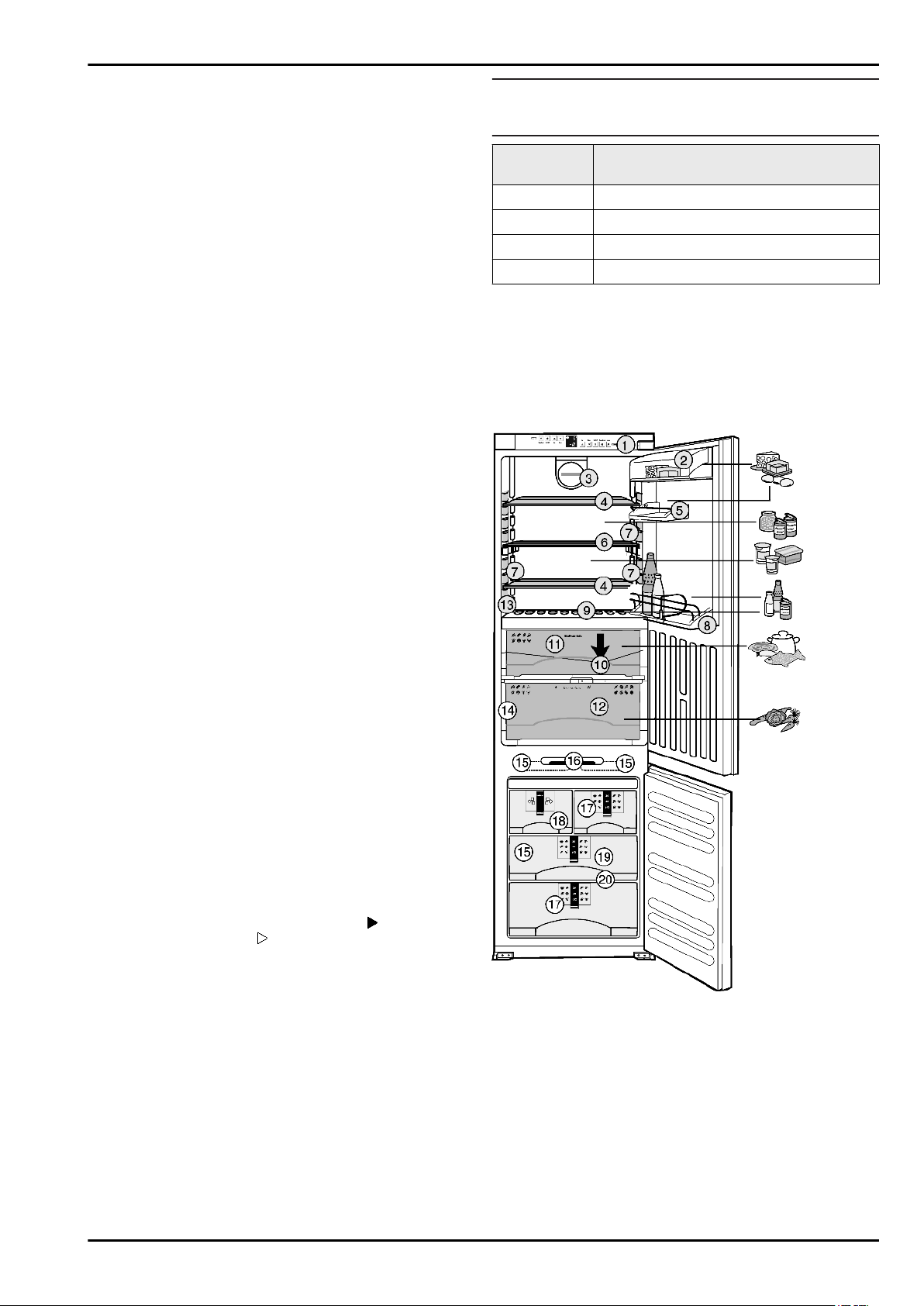
Fig. 1
(1) Operating and control el-
ements
(2) Butter and cheese com-
partment
(3) Fan (13) Type plate
(4) Shelf, relocatable (14) Interior light, Biofresh com-
(5) Egg tray* (15) Cold storage accumulator*
(6) Shelf, sectioned* (16) Interior light, freezer com-
(7) Interior light, refrigerator
compartment*
(8) Storage rack for tall bot-
tles
(11) DrySafe
(12) HydroSafe
partment*
partment*
(17) Information system*
(18) IceMaker*
2
General safety information
(9) Integrated bottle shelf or
glass shelf
(10) Drain opening (20) VarioSpace*
(19) Freezer tray*
1.4 Net@Home
The appliance can be provided with the retrofit
modules for the HomeDialog system or the serial
interface (RS 232), depending on model and
equipment. The modules are available from your
specialist dealer.
You will find more information on the internet at
www.liebherr.com.
2 General safety information
Danger for the user:
This appliance is not designed for persons (including children)
-
with physical, sensory or mental impairment or persons not
having sufficient experience and knowledge, unless they are
instructed in the use of the appliance and are initially supervised by a person responsible for their safety. Keep children
under supervision to ensure they do not play with the appliance.
In case of a fault, pull out the mains plug (not by pulling the
-
connecting cable) or switch off the fuse.
Have any repairs to or intervention in the appliance, and any
-
change of the mains power cable, carried out by the customer
service only or by other specialised personnel trained for the
purpose.
When disconnecting the appliance from the supply, always
-
take hold of the plug. Do not pull the cable.
Install and connect the appliance only as instructed.
-
Please keep these instructions in a safe place and pass them
-
on to any subsequent owners.
Fire hazard:
The refrigerant R 600a is environmentally friendly but flam-
-
mable. Escaping refrigerant may ignite.
Do not damage the refrigerant circuit pipes.
•
Do not allow naked flames or ignition sources to enter the
•
appliance.
Do not use any electrical appliances in the interior (e.g.
•
steam cleaners, heaters, ice cream maker etc.).
If refrigerant escapes: eliminate naked flames or sources
•
of ignition from the vicinity. Pull out the power plug. Ventilate the area well. Notify customer service.
Do not store explosives or sprays using combustible propel-
-
lants such as butane, propane, pentane, etc. in the appliance.
Respective spray cans can be identified by reference to the
contents printed on the can or by a flame symbol. Gases possibly escaping may ignite due to electrical components.
Only store high-percentage alcohol in tightly sealed, upright
-
containers. Alcohol possibly escaping may ignite due to electrical components.
Danger of tipping and falling:
Do not misuse the plinth, drawers, doors etc. as a step or for
-
support. This applies particularly to children.
Danger of food poisoning:
Do not consume food which has been stored too long.
-
Danger of frostbite, numbness and pain:
Avoid lasting skin contact with cold surfaces or refrigerated/
-
frozen food or take protective steps, e.g. wear gloves. Do not
consume ice cream, water ice or ice cubes immediately and
do not consume them too cold.
Please observe the specific information in the other sections:
DANGER identifies a situation involving direct
danger which, if not obviated, may result in death or severe bodily injury.
WARNING identifies a dangerous situation
which, if not obviated, may result in
death or severe bodily injury.
CAUTION identifies a dangerous situation
which, if not obviated, may result in
minor or medium bodily injury.
ATTENTION identifies a dangerous situation
which, if not obviated, may result in
damage to property.
Note identifies useful information and tips.
3 Controls and displays
3.1 Operating and control elements
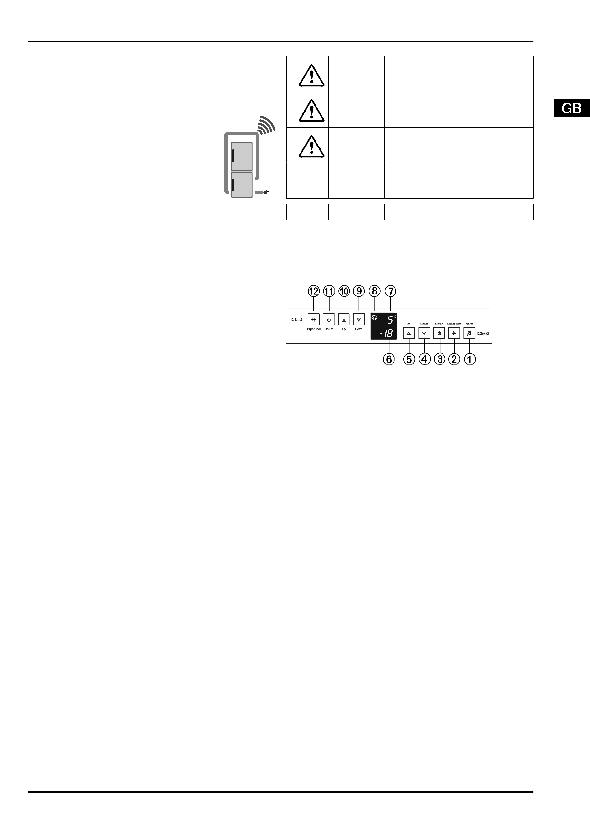
Fig. 2
(1) Alarm button (7) Temperature display re-
frigerator compartment
(2) SuperFrost button (8) Child lock symbol
(3) On/Off button freezer
compartment
(4) Down setting button
freezer compartment
(5) Up setting button freezer
compartment
(6) Temperature display
freezer compartment
3.2 Temperature display
The following are displayed in normal operation:
the warmest freezing temperature
-
the average cooling temperature
-
The freezer compartment temperature display flashes:
the temperature setting is being changed
-
after switch-on the temperature is not yet cold enough
-
the temperature has risen several degrees
-
Dashes flash in the display:
the freezer temperature is above 0 °C.
-
The following displays indicate malfunction. You will find possible
causes and corrective action in the section on troubleshooting.
nA
-
F0 to F5
-
(9) Down setting button refrig-
erator compartment
(10) Up setting button refrigera-
tor compartment
(11) On/Off button refrigerator
compartment
(12) SuperCool button
3
Putting into operation
4 Putting into operation
4.1 Changing the door hinges
ATTENTION*
Risk of damage to side-by-side appliances by condensate!
A side-by-side (SBS) appliance may be installed only with the
door hinges as delivered.
u
Do not change over the door hinges.
u
Transfer the screws
them in a little.
u
Undo the screws
agonally.
The screws
driver.
u
Screw the hinges tight.
u
Place plugs
u
Attach the doors to the prefitted screws
the screws.
Fig. 4 (10)
Fig. 4 (11)
Fig. 4 (9)
Fig. 4 (10)
are self-tapping: use a cordless screw-
to the opposite side and screw
and change over the hinges di-
in the now unused fastening holes.
Fig. 4 (9)
and tighten
Make sure the following tools are to hand:
spanner 13
q
cordless screwdriver Torx 15, 20, 25, 30
q
Slide the appliance 2/3 of the way into the recess.
Pull out the mains plug.
Open the doors.
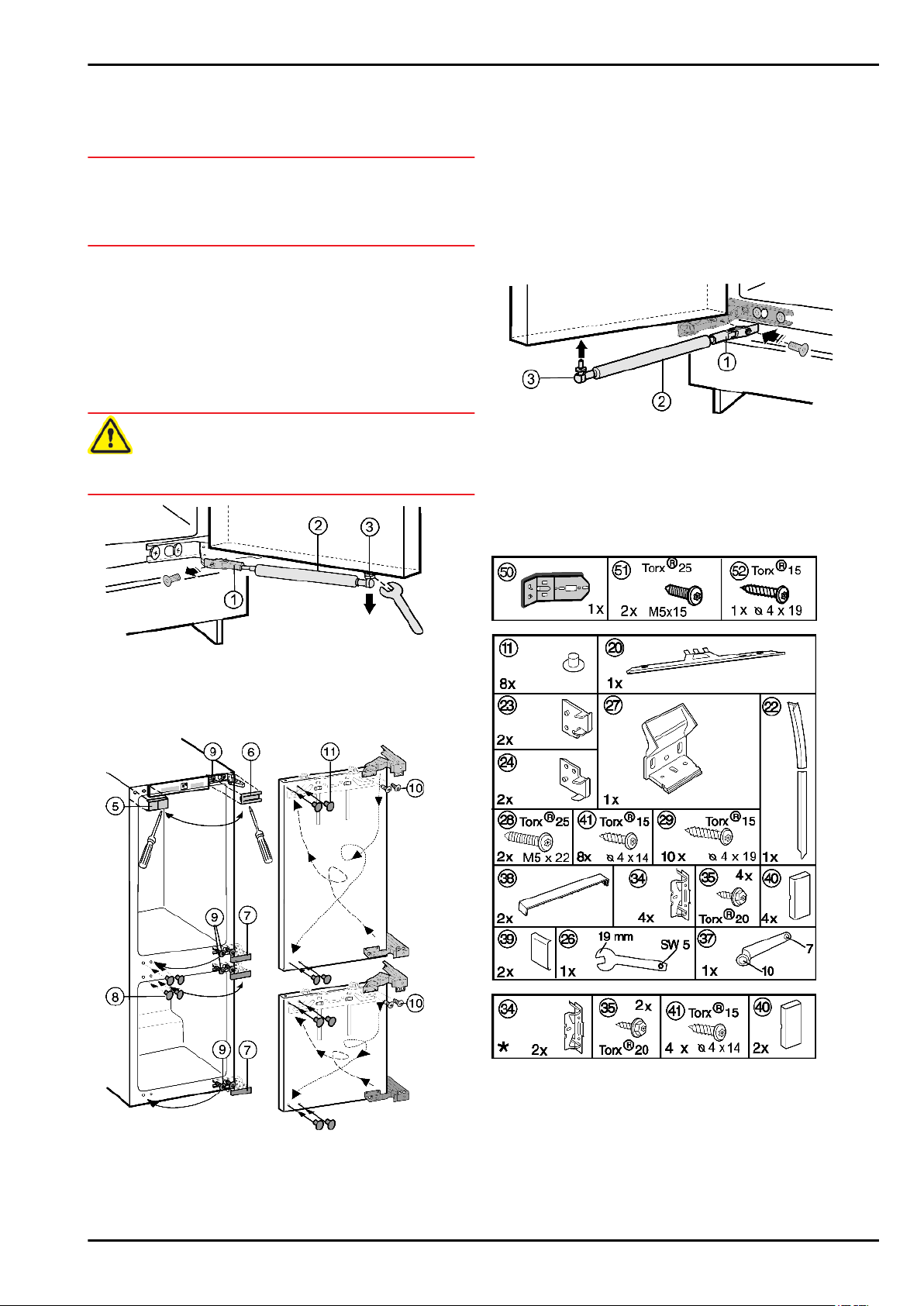
4.1.1 To detach the soft stop mechanism
CAUTION
Risk of injury if soft stop contracts!
u
Detach with care.
u
Unscrew holder
u
Unscrew the ball stud
mechanism
Fig. 3 (1)
Fig. 3 (2)
.
Fig. 3 (3)
from the door and set it aside.
together with the soft stop
Fig. 3
4.1.3 Re-fit the soft stop mechanism
u
Screw on the holder
u
Screw the ball stud
anism
u
Fig. 5 (2)
Re-fit all the covers
Fig. 5 (1)
Fig. 5 (3)
into the fastening hole.
Fig. 4 (5,6,7,8)
.
together with the soft stop mech-
.
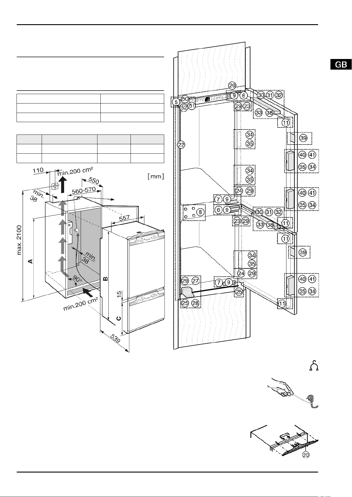
4.2 Installation
All the fasteners accompany the appliance.
Fig. 5
Fig. 6
4.1.2 To change the hinges
u
Lift off the covers
screwdriver.
u
Loosen the top and bottom screws
body, without removing them.
u
Pull the doors outwards and detach them.
Fig. 4 (5,6,7,8)
forwards using a flat-blade
Fig. 4 (9)
Fig. 4
on the appliance
Fig. 7
Fig. 8
Ensure that the following tools are to hand:
cordless screwdriver Torx®15, 20, 25
q
spanner 13
q
The shelf and side walls of the unit must be at right-angles to one
another. Align the unit with a spirit level and an angle. If necessary, level out by building up from underneath.
4
Putting into operation
The appliance can also be installed in an ordinary kitchen cabinet. In this case detach the fittings of the unit door and recess.
They are no longer needed as the unit door is fitted to the appliance door.
Note
u
Before assembling the door of the unit, make sure that the
admissable weight of the unit door is not exceeded.
u
Otherwise damage to the hinges and resultant malfunction
cannot be ruled out.
Max. weight of unit door
Refrigerator compartment door 20 kg
Freezer compartment door 12 kg
Check installation dimensions:
A B C
ICB 31 1772 mm - 1788 mm 1770 mm 549 mm
ICBN 30 1772 mm - 1788 mm 1770 mm 695 mm
4.2.1
Assembling appliance
Fig. 9
Fig. 10
u
Detach the connecting cable from the back of the appliance, removing the cable holder because otherwise
there will be vibratory noise!
u
Lay the connecting cable with the
help of a string in such a way that
the appliance can be easily connected after fitting.
u
Slide the appliance 2/3 of the way
into the recess.
u
Remove covers
u
Fit the equaliser trim
Fig. 12 (20)
the appliance: slide into
holding fixture and engage
in keyholes.
Fig. 10 (5,6,7)
centrally onto
.
Fig. 11
Fig. 12
5
 Loading...