

Page 1

LightOn/Off
Zone UpUpDown
41
On/Off SuperFrost Alarm
Down
64
0
Installation
Instructions
For wine cooler with
NoFrost freezer compartment and
Side-By-Side Units
with IceMaker
Instructions
de montage
Armoire de mise en température des
vins avec congélateur NoFrost et les
appareils côte à côte
2-6
4-8
6-12
4
Instrucciones
avec IceMaker
2-6
4-8
6-12
3
2-6
4-8
6-12
2
2-6
4-8
6-12
1
de instalación
Armario de acondicionamiento de
vinos con congelador NoFrost y
unidades lado a lado
con IceMaker
WFI1051 / EWTN/ 2956
7082 408-00
Page 2

I
MPORTANT
PLEASE READ AND FOLLOW
THESE INSTRUCTIONS
These instructions contain Warning and Caution
statements. This information is important for safe
and efficient installation.
Always read and follow all Warning and Caution
statements!
WARNING
!
States a hazard that may cause serious
injury or death if precautions are not followed.
CAUTION
!
Signals a situation where minor injury of
product damage may occur if you do not
follow instructions.
IMPORTANT
This highlights information that is especially
relevant to a problem-free installation.
Make sure incoming voltage is the same as the unit
rating.
To reduce the risk of fire, electric shock, or personal injury, installation work and electrical wiring must
be done by a qualified electrician in accordance
with all applicable codes and standards, including
fire-rated construction.
A delight in freshness
ii
WFI1051 / EWTN 2956
Page 3

TO THE INSTALLER
It is very important that the guidelines and
instructions are followed in the manual to ensure
proper installation and operation of the unit. The
Installation Guidelines section contains important
information for making sure the installation is correct. Read and understand all the information in
Installation Guidelines, and in this manual before
the unit is installed.
I
MPORTANT
WFI1051 / EWTN 2956
A delight in freshness
1
Page 4

T
ABLE
OF
Contents Page
Installation Guidelines ................................................................................. 3
Area Requirements ............................................................................... 3
Electrical Requirement .......................................................................... 3
Customer’s Responsibility .................................................................... 3
Blocking For Safety ............................................................................... 3
Unit Venting ........................................................................................... 3
Planning Information ................................................................................... 4
Cabinet Opening Dimensions ............................................................... 4
Assembling Decorative Panels ................................................................... 7
Integrating Cabinetry ................................................................................... 8
Framed Panels ...................................................................................... 8
Overlay Panels ...................................................................................... 9
Reversing Door Hinges ............................................................................. 14
Door Opening Angle ........................................................................... 17
Installation ................................................................................................. 18
Blocking For Safety ................................................................................... 22
IceMaker .................................................................................................... 23
Water Connection ............................................................................... 23
Connection to the Water Supply ......................................................... 24
Side-By-Side Installation ........................................................................... 25
C
ONTENTS
A delight in freshness
2
WFI1051 / EWTN 2956
Page 5

I
NSTALLATION
G
UIDELINES
Area Requirements
Verify the following:
• Floors can support refrigerator’s weight plus
approximately 1200 pounds (544 kg) of food
weight.
• Finished kitchen floor height has to be level.
Appliance must be shimmed to the floor level if
the floor heights are not equal to make sure air
vents are not obstructed.
• Remove anything attached to rear or side walls
that can obstruct refrigerator opening.
• Cutout dimensions are accurate.
• Electrical outlet is in correct location.
Do not install this unit next to any other refrigerator
or freezer except another Liebherr model. Liebherr
models are designed to allow side-by-side installation. They are equipped with a heating system
to eliminate condensation when units are installed
side by side. Installing this unit next to any other
refrigerator or freezer can cause condensation or
cause damage to the Liebherr unit.
WARNING
!
ELECTROCUTION HAZARD
Electrical Grounding Required. This appliance is equipped with a three-prong
(grounding) polarized plug for your protection against possible shock hazards.
DO NOT remove the round grounding
•
prong from the plug.
DO NOT use a two-prong grounding
•
adapter.
DO NOT use an extension cord to
•
connect power to the unit.
Customer’s Responsibility
A 115 Volt, 60 Hz, 15 Amp (20 Amp for side-byside installation) fused electrical supply is required.
We recommend using a dedicated circuit for this
appliance to prevent electrical overload. Follow the
National Electrical Code and local codes and ordinances when installing the receptacle.
Blocking For Safety
The anti-tip brackets must be installed to prevent
the unit from tipping after it is installed. Refer to
Blocking For Safety.
Electrical Requirement
If codes require a separate grounding circuit to be
used, have a qualified electrician install the circuit.
WARNING
!
Do not ground to a gas pipe. Check with
a qualified electrician if you are not sure
the appliance is properly grounded. Do not
have a fuse in the neutral or grounding
circuit.
WARNING
!
ELECTRICAL SHOCK HAZARD
• Electrically ground refrigerator.
• Do not use an extension cord.
• Failure to follow these instructions
could result in fire or electrical shock.
Unit Venting
DO NOT restrict the air flow. Air flow must be provided for the unit to operate. The factory air vents
provide 31 square inches (200 cm²) of air flow per
unit. If you are replacing the factory air vents with
an overlay, the air flow must be the same or greater
than the factory air vents.
WFI1051 / EWTN 2956
A delight in freshness
3
Page 6
P
LANNING
I
NFORMATION
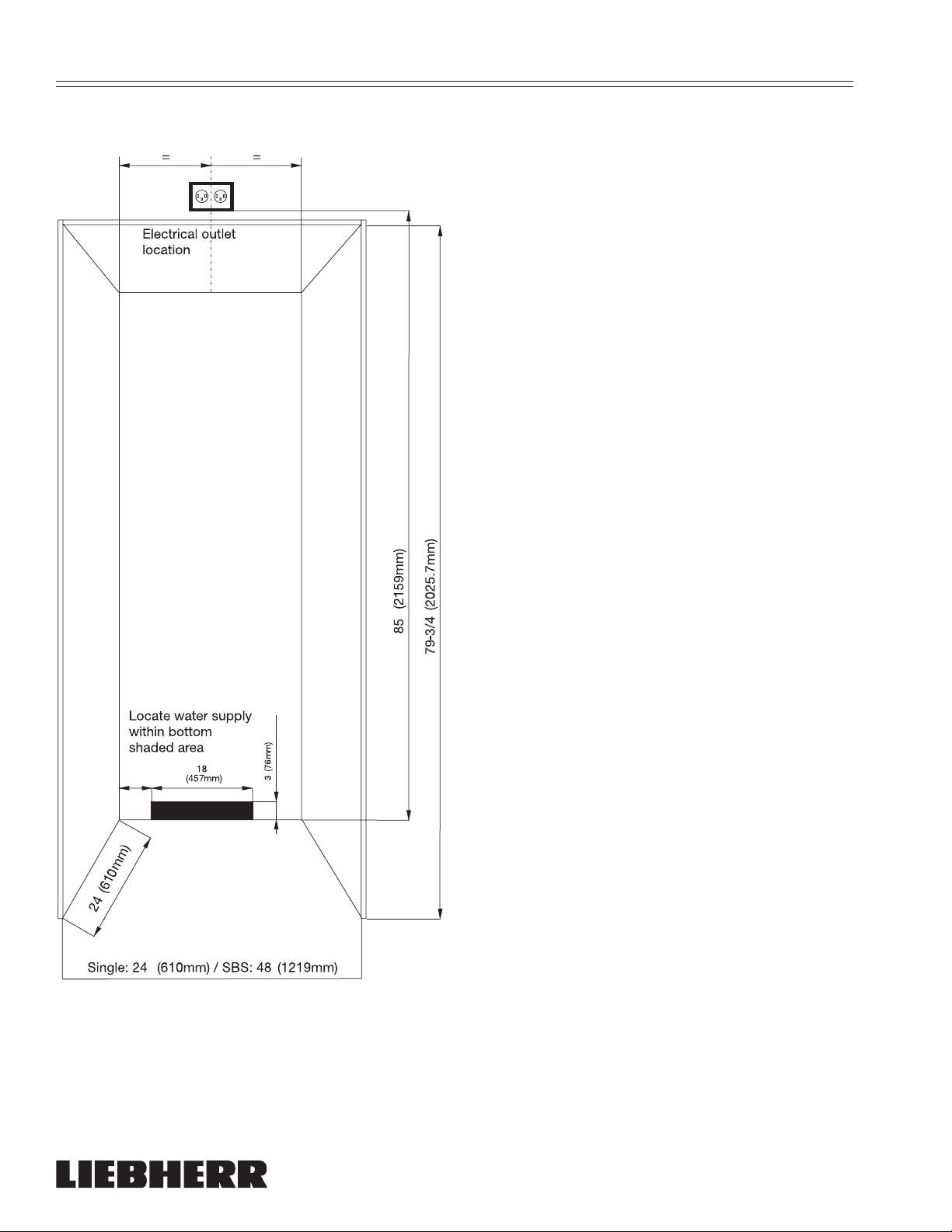
Cabinet Opening Dimensions - Figure 1
Allow units to open a minimum of 90° to prevent
problems removing drawers. With the door opening 90°, you may have to move drawers slightly to
clear the door interior.
Refer to the minimum door clearances in the PreInstallation Specifications chart.
• Allow for a minimum 3-3/4" (95 mm) filler, for
corner installations, so the door can open to 90°.
If you’re using raised panels, consider using a
wider filler.
IMPORTANT
Refer to the full scale illustrations at the end of
this section for specifics on door openings and
filler size alternatives.
"
3"
(76mm)
"
"
"
"
Figure 1
"
"
A delight in freshness
4
WFI1051 / EWTN 2956
Page 7

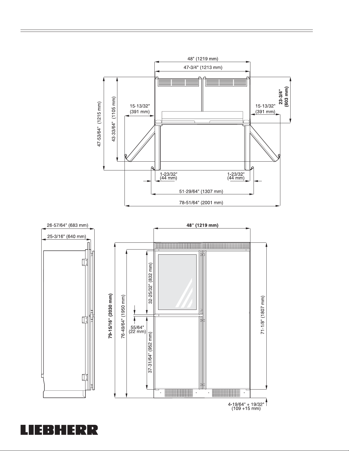
WFI 1051 - Figure 2
P
LANNING
I
NFORMATION
WFI1051 / EWTN 2956
Figure 2
A delight in freshness
5
Page 8
P
LANNING
Side-By-Side WFI 1051 - RBI 1400 - Figure 3
I
NFORMATION
A delight in freshness
6
WFI1051 / EWTN 2956
Page 9
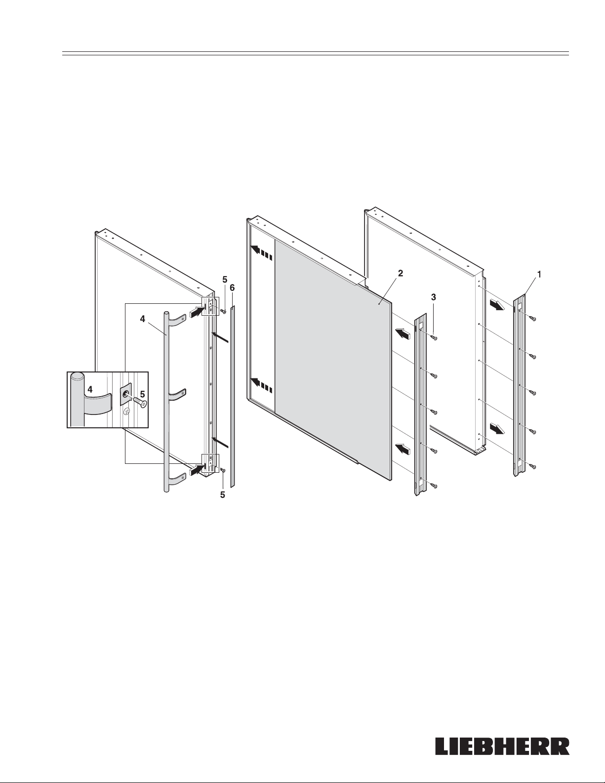
A
SSEMBLING
Figure 4
Proceed as shown in the illustration:
(1) Door change frames
(2) Decorative panel
(3) Screws for door change frames
(4) Handle, depending on model
(5) M4 x 10 screws for handle
(6) Filler strip
D
ECORATIVE
P
ANELS
WFI1051 / EWTN 2956
Figure 4
A delight in freshness
7
Page 10
I
NTEGRATING
C
ABINETRY
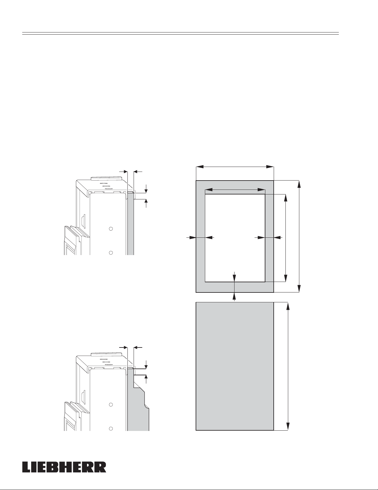
Framed Panels - Figure 5
If the thickness of the custom panels is less than
1/4" (6.4 mm), they must be backed up with a sheet
of shim material to build the total thickness to 1/4"
(6.4 mm). If the panel is thicker than 1/4" (6.4 mm),
an edge must be routed around the panel to
ensure a proper fit.
1/4"
(6.4 mm)
1/4" (6.4 mm)
IMPORTANT
If you are replacing the factory air vents with
an overlay, DO NOT restrict the air flow. The air
flow must be the same or greater than the factory air vents of 31 square inches (200 cm²).
The door handles must be installed before the
screw covers are installed. If you fail to install
the handles before the screw covers, you can
damage the covers. The screw covers are
taped to the unit doors during shipping. Use
care when removing covers.
The door panel weight must not exceed
25 lb (11,3 kg).
22-9/16" (573 mm)
max. 17-1/2" (445 mm)
Window cutout
= =
1/4"
(6.4 mm)
1/4" (6.4 mm)
3-1/16"
(78 mm)
32-37/64" (828 mm)
max. 25-1/2" (648 mm)
37-9/32" (947 mm)
Figure 5
A delight in freshness
8
WFI1051 / EWTN 2956
Page 11
I
NTEGRATING
C
ABINETRY
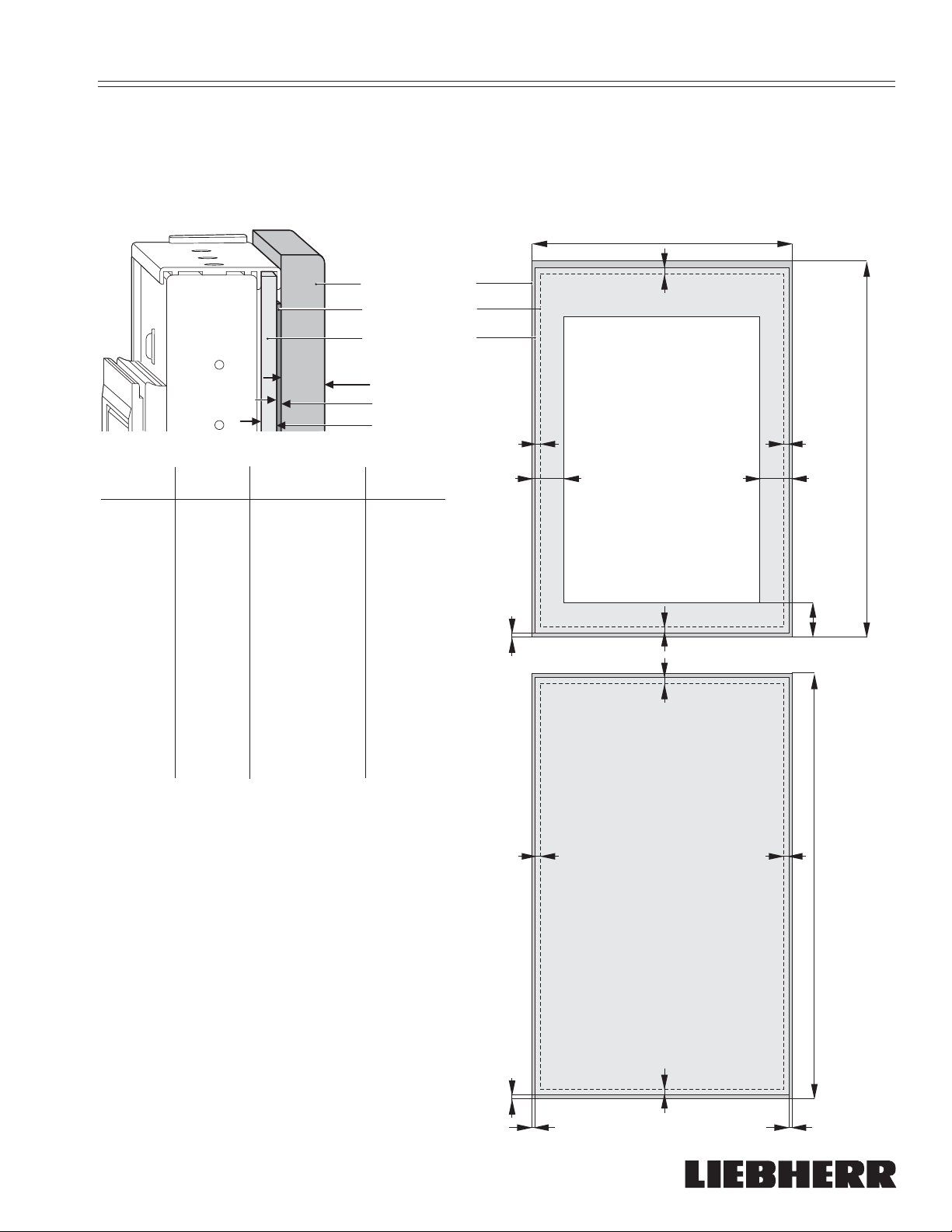
Overlay Panels - single install - Figure 6
The overlay design line allows decorative panels to
cover the door trim for a more seamless appearance that blends with the design of the room. To
achieve this look, the most common way is to work
1 Overlay Panel
2 Spacer Panel
3 Backer Panel
Approx. 3/4"
(19.1mm)
3/32" (2.5mm)
1/4" (6.4mm)
W
H - Winecooler H - Freezer
1 Overlay
Panel
23-5/16"
(592 mm)
33-5/8"
(854 mm)
38"
(965 mm)
with three panels, the decorative overlay panel, a
3/32" (2.5 mm) spacer panel and a 1/4" (6.4 mm)
backer panel.
Depending on your cabinet manufacturer, this could
be one panel routed for different dimensions or,
more likely, three different panels.
W
=
Window cutout
= =
==
H
Winecooler
2 Spacer
Panel
3 Backer
Panel
Window
cutout
21-3/4"
(553 mm)
22-3/4"
(576 mm)
max17-1/2"
(445 mm)
31-1/2"
(800 mm)
32-37/64"
(828 mm)
max 25-1/2"
(648 mm)
36-1/4"
(921 mm)
37-9/32"
(947 mm)
IMPORTANT
If you are replacing the factory air vents with an
overlay, DO NOT restrict the air flow. The air flow
must be the same or greater than the factory air
vents of 31 square inches (200 cm²).
The door handles must be installed on the
overlay panels before the screw covers are
installed. If you fail to install the handles on
the overlay panels before the screw covers ,
you can damage the covers. The screw covers
are taped to the unit doors during shipping.
Use care when removing covers.
3/8"
(9mm)
=
=
==
3-1/16"
(78mm)
H
Freezer
The door panel weight must not exceed
25 lb (11,3 kg).
Figure 6
WFI1051 / EWTN 2956
3/8"
(9mm)
A delight in freshness
9
=
==
Page 12

I
NTEGRATING
C
ABINETRY
Overlay Panels - side by side install
The overlay design line allows decorative panels to
cover the door trim for a more seamless appearance that blends with the design of the room. To
achieve this look, the most common way is to work
1 Overlay Panel
2 Spacer Panel
3 Backer Panel
Approx. 3/4"
(19.1mm)
3/32" (2.5mm)
1/4" (6.4mm)
W
H - Winecooler H - Freezer
1 Overlay
Panel
23-5/16"
(592 mm)
33-5/8"
(854 mm)
38"
(965 mm)
with three panels, the decorative overlay panel, a
3/32" (2.5 mm) spacer panel and a 1/4" (6.4 mm)
backer panel.
Depending on your cabinet manufacturer, this could
be one panel routed for different dimensions or,
more likely, three different panels.
W
=
==
Window cutout
= =
H
Winecooler
2 Spacer
Panel
3 Backer
Panel
Window
cutout
21-3/4"
(553 mm)
22-3/4"
(578 mm)
max17-1/2"
(445 mm)
31-1/2"
(800 mm)
32-37/64"
(828 mm)
max 25-1/2"
(648 mm)
36-1/4"
(921 mm)
37-9/32"
(947 mm)
IMPORTANT
If you are replacing the factory air vents with an
overlay, DO NOT restrict the air flow. The air flow
must be the same or greater than the factory air
vents of 31 square inches (200 cm²).
The door handles must be installed on the
overlay panels before the screw covers are
installed. If you fail to install the handles on
the overlay panels before the screw covers ,
you can damage the covers. The screw covers
are taped to the unit doors during shipping.
Use care when removing covers.
3/8"
(9mm)
Handle Side
=
=
==
3-1/16"
(78mm)
H
Freezer
Hinge Side
The door panel weight must not exceed
25 lb (11,3 kg).
3/8"
(9mm)
A delight in freshness
10
=
3/16"
(4.7mm)
WFI1051 / EWTN 2956
Page 13

I
NTEGRATING
C
ABINETRY
Figure 7
C
The factory setting for the door to swing open is
130°. Use this illustration to ensure other cabinets or counters do not interfere with the door
opening.
Frameless cabinets: The casing trim overlaps
the cabinets at the side and top. Cabinets may
require filler strips to prevent interference with
the cabinet door swing. The door opening must
allow for filler strips.
1"
(25.4 mm)
1-1/4"
(31.8 mm)
(12.7 mm)
(19.1 mm)
(25.4 mm)
(6.4 mm)
3/4"
1"
1/4"
1/2"
3"
(76.2 mm)
2-3/4"
(69.9 mm)
2-1/2"
(63.5 mm)
(57.2 mm)
2"
(50.8 mm )
1-3/4"
(44.5 mm)
1-1/2"
(38.1 mm)
2-1/4"
3/4"
(19.1 mm)
(12.7 mm)
(1219.2 mm)
A
1/2"
1/4"
(6.4 mm)
24" (609.6 mm)
48"
1"
(25.4 mm)
3/4"
(19.1 mm)
1/2"
(12.7 mm)
1/4"
(6.4 mm)
3/32"
(2.4 mm)
D
LBR026
Figure 7
WFI1051 / EWTN 2956
A delight in freshness
11
Page 14

I
NTEGRATING
Figure 8
The optional setting for the door to swing open is
90°. Use this illustration to ensure other cabinets or
counters do not interfere with the door opening.
Frameless cabinets: The casing trim overlaps the
cabinets at the side and top. Cabinets may require
filler strips to prevent interference with the cabinet
door swing. The door opening must allow for filler
strips.
C
ABINETRY
A delight in freshness
12
WFI1051 / EWTN 2956
Page 15

I
NTEGRATING
C
ABINETRY
(25.4 mm)
1-1/4"
(31.8 mm)
1-1/2"
(38.1 mm)
(12.7 mm)
3/4"
(19.1 mm)
1"
1/4"
(6.4 mm)
1/2"
3"
(76.2 mm)
2-3/4"
(69.9 mm)
2-1/2"
(63.5 mm)
2-1/4"
(57.2 mm)
(2.4 mm)
2"
(50.8 mm )
3/32”
C
1-3/4"
(44.5 mm)
1-1/2"
(38.1 mm)
(25.4 mm)
1-1/4"
(31.8 mm)
1"
(19.1 mm)
3/4"
1/2"
(12.7 mm)
(6.4 mm)
24”
(609.6 mm)
48”
(1219.2 mm)
A
1/4"
WFI1051 / EWTN 2956
1/4"
(6.4 mm)
1/2"
(12.7 mm)
3/4"
(19.1 mm)
1"
(25.4 mm)
Figure 8
A delight in freshness
13
D
LBR025
Page 16

7
R
EVERSING
The door hinges can be changed from one side to
the other if required.
1. Figure 10: Top: Unscrew the hinge pin (2) and
remove the screw (5) with the eccentric.
2. Swivel out the door at the top, ensuring that
you do not lose the stop (7) and bushing (8); lift
off the door and place it on the floor.
3. Center: Pull out the hinge pin (9) with its washer.
4. Swivel out the lower door, lift it out and place it
on the floor. Take care not to lose the stop (7)
and washers (8).
5. Unscrew all the door fittings (14, 15, 16, 17).
6. Figure 11: Unscrew all the door change frames
and exchange them with one another (6 with 8,
4 with 7 and handle - remove cover 1). Secure
them in position using the same screws.
7. Ensure that the door change frames are correctly positioned and mitered.
WARNING
!
D
OOR
H
INGES
8
8
LBR02
Figure 10
Make sure the corners of the door change
frames are positioned correctly. Sharp
edges will be exposed if they are not
mitered or positioned correctly.
Figure 11
A delight in freshness
14
WFI1051 / EWTN 2956
Page 17

R
EVERSING
D
OOR
H
INGES
8. Figure 12: Unscrew the lower hinge (13).
- Remove the stop and bushings (7, 8).
- Transfer hinge pin (2) to the opposite side.
- Turn the stop (7) 180° and position bushings (8) as shown in the detailed drawing.
- Screw on hinge (13) on the new hinge side.
9. On the lower door: Reinstall the door fittings
(14, 15). Pay special attention to the part (14)
with the stop.
10. Unscrew the center hinge (10) and cover (11),
pull them off to the side and after turning
them 180°, slide them on again on the opposite
side and secure them.
11. Place the lower door on the hinge pin (2) at the
bottom.
- Swivel in the door.
- Pay special attention to the bushing (12) in the
center hinge (10).
- Insert hinge pin (9) and add the washer.
WFI1051 / EWTN 2956
LBR029
Figure 12
A delight in freshness
15
Page 18

R
180
°
EVERSING
D
OOR
H
INGES
12. Figure 13: Lift up cover (3) on handle side,
push outward; lift up cover (1) on hinge side
and pull off.
13. Unscrew mounting plate (21): first mounting
screw (20), then inner retaining screw (25).
- Unscrew hinge (4): first remove the mount-
ing screw (20), then retaining screws (25). Fit
hinge (4) to opposite side: for easy assembly, fit hinge from above and first tighten
with the upper retaining screw (25) M5, then
screw (25) and finally mounting screw M4 (20).
- Turn mounting plate (21) 180° and screw tight
again on the new handle side: first retaining
screw (25), then mounting screw (20).
20
25
4
180°
25
21
20
14. Remove the eccentric (5) with the retaining
screw in the hinge (4).
15. On the upper door: Reinstall the door fittings
(16, 17). Pay special attention to the fitting (17)
with the stop.
16. Place the upper door on the center hinge, fit the
bushing (8), stop (7) and washer on the door,
swivel in the door at the top and insert and
secure the hinge pin (2) from above through the
hinge and stop.
17. Re-insert the eccentric (5) with the retaining
screw as shown in the detailed drawing.
Check for proper alignment of all doors. Adjust
them if necessary using the slots on the hinge.
21
4
12
14
15
17
16
15
Figure 13
A delight in freshness
16
WFI1051 / EWTN 2956
Page 19

R
EVERSING
Door Opening Angle - Figures 14, 15
The appliance is delivered with a door opening
angle of 130°.
If the angle is to be decreased to 90°, proceed as
follows:
• Insert attached screw (6) in the upper hinge as
shown in Figure 14.
• Insert attached screw (6) in the lower hinge as
shown in Figure 15.
D
OOR
H
INGES
Figure 14
Figure 15
WFI1051 / EWTN 2956
A delight in freshness
17
Page 20

I
NSTALLATION
Only install the winecooler/freezer in a stable kitchen cabinet that has been properly aligned.
- Mount and fix the handles, depending on your
model and choice.
Unpacking
Unpack the installation kit and check with the provided parts list if all parts are included.
The part numbers given in the parts list are identical
to the numbers in the respective fi gures.
For installation you will need the following tools:
Included:
- Star Key Torx® 15
- Star Key Torx® 20
- Star Key Torx® 25
- Socket Wrench 8 mm
- Open-end Wrench 10 mm
Not in package:
- Phillips (star) screwdriver
- Level
- Ruler
Figure 16: Installation with Ventilation Grille Set:
1. Screw the installation frame at the top (1) onto
the appliance with screws (2).
2. Place the ventilation grille (3) on this, align it in
the center and secure at the front from underneath.
3. Slide brackets (4) onto the side installation
frames (5) from above and below.
4. Using the frame (5), screw the brackets onto
the side wall*.
5. Slide the side installation frames (5) upwards
until they are in contact with the underside of
the ventilation grille.
6. Secure the side frames with the adhesive section (7) to prevent them from sliding down.
Remove the protective film and affix the adhesive sections over the upper brackets on the
handle and hinge sides.
* Depending on model and options
A delight in freshness
18
LBR034
Figure 16
WFI1051 / EWTN 2956
Page 21

I
6
NSTALLATION
- Figure 17: Connect the appliance to the
main power supply.
- If the appliance is equipped with an
IceMaker, establish the connection for
the water supply. See “IceMaker, Water
Connection”.
1
1 2
1. Carefully slide the appliance into the cabinet
until the ventilation grille touches the surrounding kitchen cabinet.
2. Align the appliance until it is parallel with the
surrounding kitchen cabinet. Use the openend wrench 10 mm (3) to adjust the feet at the
front. Turn clockwise for up and counterclockwise for down. For the rear use the adjusting
2
3
2
2
3
8 spanner
3
Figure 17
3. Figure 18: Align the appliance at the side with the
4. Fit the ventilation grille at the bottom [(3) if the
10 spanner
bolt (2). Turn clockwise for down and counterclockwise for up.
Maximum adjustment: 19/64" (15 mm).
cabinet side panel and attach it with screws (1).
- Cover the screws with cover caps (2).
door is hinged on the left, (4) if it is on the right]:
Secure the ventilation grille so that it touches
the floor and then adjust it using the slots.
WFI1051 / EWTN 2956
LBR03
Figure 18
A delight in freshness
19
Page 22

I
NSTALLATION
The following ventilation cross-section
and distances must be observed:
- There must be a ventilation space of
at least 31 square inches (200 cm²)
per appliance in the cabinet plinth
and under the cabinet top panel.
- The depth of the ventilation duct at
the rear of the cabinet must be at
least 1-1/2" (38 mm).
Alternatively:
1. For built-in appliances without ven-
tilation grilles and only with an installation frame, ventilation must take place
through the ventilation duct at the rear
of the cabinet.
Built-in appliances with an installation
frame:
• Figure 19:
- Screw the complete installation
frame (2) to the appliance.
1 1/2”
(38mm)
At least 31 square inches (200cm2)
”
/4
)
3
m
0
m
2
7
2
5
(
1
2
1
2. Built-in appliances with a wooden
ventilation grille:
Figure 20: Cut out the wooden trim
for use as a ventilation grille using the
enclosed template.
- The required ventilation cross-section must be at least 31 square
inches (200 cm²) when a single
appliance is installed, which corresponds to template “small” (If you
install two appliances side-by-side,
the cross-section must be at least
62 square inches, (400 cm²), which
corresponds to template “doublesize;” for more information see “Sideby-Side Installation”).
• Remove the attachment bracket (2)
from the installation frame and screw it
to the appliance (1) from underneath.
Place the wooden ventilation grille (5)
on the appliance, align it in the center
and secure it from the rear using the
attachment bracket (2).
Figure 19
2
1
(609,6 mm)
3-11/16"
(93,7 mm)
5
24"
1/2"
(13 mm)
A delight in freshness
20
Figure 20
WFI1051 / EWTN 2956
Page 23

N
OTES
WFI1051 / EWTN 2956
A delight in freshness
21
Page 24

B
LOCKING
F
OR
S
AFETY
Figure 21: Secure the appliance in place so it does
not tip forward when the fully stocked door is
opened.
2. Measure the distance from the floor to the
upper edge of the unit.
3. Locate and mark two wall studs (1) against the
wall where the refrigerator will be located. The
space between the unit top and the bottom of
the brackets must not be more than
1/4" (6.4 mm).
4. Make sure the screws (2) extend a minimum of
1" (25.4 mm) into each of the wall studs.
5. Make sure the anti-tip brackets (3) extend
at least 3" (76.2 mm) over the unit and are
securely in place.
IMPORTANT
The anti-tip brackets can be installed in either
direction or closer together. Always position
the anti-tip brackets as wide apart as possible, but make sure they are anchored to two
studs.
6. Using the adjustable roller base, raise the unit
until it makes contact with the brackets. Make
sure the front levelers are firmly on the floor to
prevent appliance from tipping forward.
IMPORTANT
If your unit is positioned in between the
wall studs, a board can be secured to the
wall. Make sure the board is secured to the
studs with screws that will penetrate into the
studs a minimum of 1" (25.4 mm). The board
should be a minimum of 1" x 6" (25.4 mm x
152.4 mm) and long enough to secure both
ends to the wall studs.
3
1
min 3"
Figure 21
A delight in freshness
22
WFI1051 / EWTN 2956
Page 25

Water Connection - Figure 22
Please read the first three points of the safety
instructions and warnings before connecting the
appliance to the main water supply.
• The water pressure must be between 21.8-
87.0 psi (1.5-6 bar).
• Use a 1/4" OD copper line to connect the water
supply to the solenoid valve. This is not sup-
plied with the appliance (Figure 22).
• A shut-off valve, such as the saddle valve illustration here, must be installed between the hose
line and the main water supply so the water supply can be stopped if necessary.
I
CE
M
AKER
Do not install the shut-off valve behind the
appliance.
Figure 22
• If you have hard water, we recommend you install
a water softener. Also, a filter must be installed if
the water contains solids such as sand.
• All equipment and devices used to supply the
water to the appliance must comply with the current regulations for your geographical area.
WFI1051 / EWTN 2956
A delight in freshness
23
Page 26

I
CE
M
AKER
Connection to the Water Supply
1. Install the shut-off valve, water filter and automatic shut-off device as required.
Note
The solenoid valve is located at the rear of
your unit.
2. Place a 1/4" OD copper tubing between the
shut-off valve and solenoid valve. Make sure
there is approximately 30" (70 cm) of excess
tubing behind the unit for easy connection.
IMPORTANT
The solenoid valve has a Metric R3/4 male
connection.
A R3/4(metric) to a 1/4" OD adapter and
cable clip are supplied with the icemaker.
Figure 24: Remove the cover cap (4) from
the solenoid valve (1). Install the connection
bracket (2) with sealing ring (6) on the solenoid
valve (1). Attach the copper tube to the connection bracket (2). Secure the copper tube (3) to
the appliance using the cable clip (5).
3. Open the shut-off valve for the water supply
and check the entire water system for leaks.
Before the appliance is used for the first time a
licensed plumber should bleed air from the system.
4. Insert the electrical plug for the combined appliance into the electrical outlet (Figure 23).
5. Move the appliance into final position in the
room.
Figure 23
A delight in freshness
24
WFI1051 / EWTN 2956
Page 27

S
IDE
4
-B
Y
-S
1
IDE
I
NSTALLATION
WFI1051 / EWTN 2956
1
6
2
3
5
5
Figure 24
A delight in freshness
25
Page 28

S
IDE
-B
Y
-S
IDE
I
NSTALLATION
Unpacking
Unpack the side by side installation kit and check
with the provided parts list if all parts are included.
The part numbers given in the parts list are identical
to the numbers in the respective fi gures.
For installation you will need the following tools:
Included:
- Star Key Torx® 15
- Star Key Torx® 20
- Star Key Torx® 25
- Socket Wrench 8 mm
- Open-end Wrench 10 mm
Not in package:
- Phillips (star) screwdriver
- Level
- Ruler
Figure 25: To install the WFI 1051 appliances sideby-side, proceed as follows:
- Always place the WF/WFI 1051 with the hinges
on the left-hand side (looking from the front).
Installation with SBS Ventilation Grille Set:
1. Affix the spacer (1) on the side wall of the appli-
ance – remove the protective film.
2. Push the appliances together,
- align them parallel to each other.
3. Use a level on the top to align them to the
same height:
4. Use the open-end wrench 10 mm (3) to adjust
the feet at the front of the roller base. Turn
clockwise for up and counterclockwise for down.
For the rear, turn the adjusting bolt (2) clockwise down and counterclockwise up.
Figure 25
A delight in freshness
26
4
WFI1051 / EWTN 2956
Page 29

S
IDE
-B
Y
-S
IDE
I
NSTALLATION
5. Figure 26: Secure the installation frame (3)
at the top to the appliances with screws (2).
- Align the appliance at the front bottom.
- Use the predrilled holes to align the
installation frame (2).
- First mount the installation (3) frame with
4 screws (2) to one appliance, then align
the other appliance with the predrilled
holes to the installation frame (3) and
secure it with the screws (2).
6. Figure 26: Position the attachment brack-
ets (6) at the rear of the appliances at the
top and bottom. Slide the upper attachment
bracket upwards as far as possible. Secure it
at the side using the screws provided (5). Do
not overtighten!
5
2
3
6
A delight in freshness
6
Figure 26
8-1/4"
ca. (210)
6
5
5
6
WFI1051 / EWTN 2956
27
Page 30

S
IDE
7. Figure 27: Push the long carriage bolt
M5x260 (7) through the leveling wheels as shown.
Fit in a washer (8). Screw on the wing nut (9) and
tighten it manually. Do not overtighten.
8. Turn the adjustable roller base up. Otherwise
you will damage the floor when you push in the
appliances.
9. Secure the ventilation grille (10) to the appliance with screws (11). Push in the sealing
strip (4) as shown.
-B
Y
-S
IDE
I
NSTALLATION
10
9
11
9 8 7
4
7
4
10 spanner
Figure 27
A delight in freshness
28
7
8 spanner
2
3
WFI1051 / EWTN 2956
8
Page 31

S
IDE
-B
Y
-S
IDE
I
NSTALLATION
10. Figures 28, 29: Slide the side installation
frames (15) upward until they are in contact with the underside of the ventilation
grille, Figure 28.
11. Secure the side frames with the adhesive section (17) to prevent them from
sliding down. Remove the protective film
and place the adhesive sections over the
upper brackets.
12. Install anti-tip brackets for each appliance.
Refer to “Blocking For Safety.”
10
15
17
17
11
15
11
17
min 3"
Figure 29
A delight in freshness
Figure 28
WFI1051 / EWTN 2956
29
Page 32

S
IDE
13. Figure 30, 31: Connect the appliances:
- to the main power supply and
- to the water supply if the appliance is equipped
with an IceMaker. See “IceMaker, Water
Connection,” Figure 30.
14. Carefully slide the connected appliances into the
recess until the ventilation grille touches the top,
Figure 31.
-B
Y
-S
IDE
I
NSTALLATION
15. Align the appliances by using only the outer leveling wheels at the front (3) and rear (2).
13
Figure 30
14
10 spanner
Figure 31
A delight in freshness
30
15
2
8 spanner
3
LBR042
WFI1051 / EWTN 2956
Page 33

S
IDE
16. Figure 32: Attach the aligned combination
to the surrounding kitchen cabinet. Secure it
through the side frames using the screws (20)
provided.
- Cover the screws with cover caps (21).
17. Now adjust the center adjustable roller
bases (22) so that they make slight contact
with the floor.
18. Install the lower ventilation grille (23): Secure
the ventilation grille so that it touches the floor
and adjust it using the slots. Do not overtighten!
-B
Y
-S
IDE
I
NSTALLATION
20
22
16
17
18
10 spanner
24
2
21
8 spanner
3
WFI1051 / EWTN 2956
24
24
23
24
Figure 32
A delight in freshness
31
LBR043
Page 34

S
IDE
-B
Y
-S
IDE
I
NSTALLATION
1. For built-in appliances without ventilation
grilles and only with installation frame (2), ven-
tilation must take place through the ventilation
duct at the rear of the cabinet. Ensure that the
ventilation cross-section is at least 31 square
inches (200 cm²) per appliance.
At least 62 square inches (400 cm²) for side-byside installation of two appliances. Built-in appliances with an installation frame:
- Figure 33: Screw the installation frame (2) to
the appliance through the attachment brackets.
1 1/2”
(38mm)
At least 31 square inches (200cm2)
”
/4
)
3
m
0
2
m
7
2
”
5
(
/4
)
3
0
m
2
m
7
2
5
(
per unit
1
2
Figure 33
A delight in freshness
32
WFI1051 / EWTN 2956
Page 35

S
IDE
-B
Y
-S
IDE
I
NSTALLATION
Built-in appliances with a wooden ventilation
grille:
2. Figure 34: Cut out the wooden trim for use as
a ventilation grille using the attached template.
- The required ventilation cross-section must
be at least 62 square inches (400 cm²) for
side-by-side installation of two appliances,
which corresponds to the attached template
“double-size.”
- Remove the attachment brackets from the
installation frame (2) and screw them to the
appliance from underneath.
- Place the wooden ventilation grille (5) on the
appliance, align it in the center and secure it
from the rear using the attachment brackets.
2
WFI1051 / EWTN 2956
3-11/16"
(93,7 mm)
Figure 34
A delight in freshness
33
48"
(1219,2 mm)
5
1/2"
(13 mm)
 Loading...