

Page 1
Excavators Electric
Material Handlers
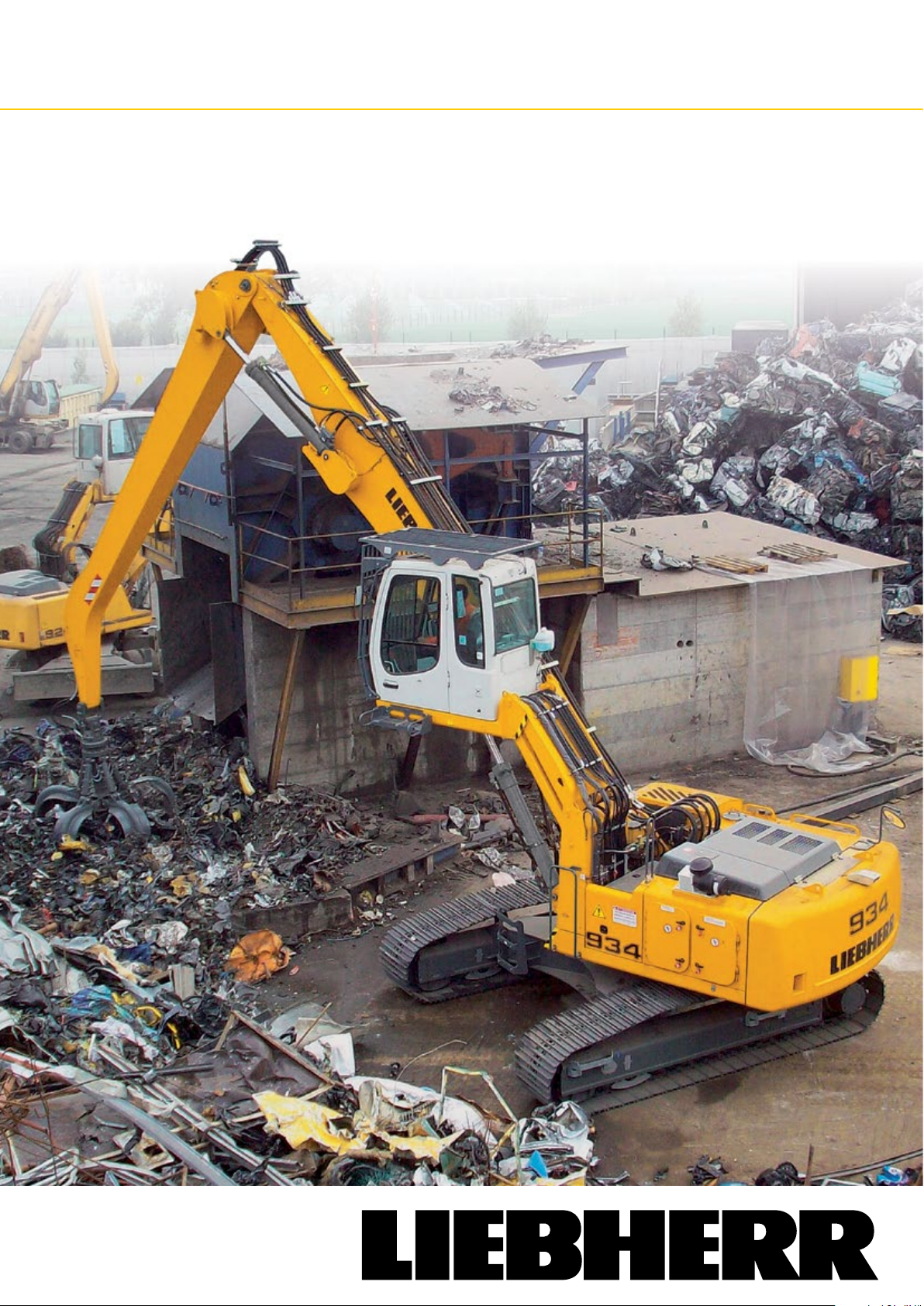
ER 934 C - ER 954 C
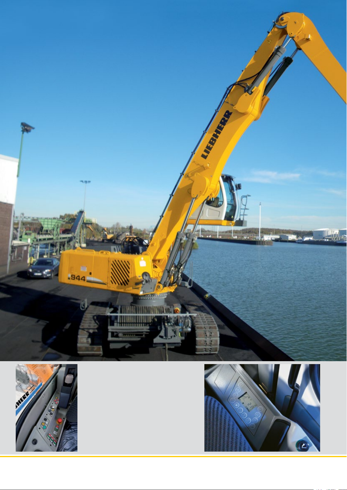
ER 934 C Operating Weight: 38,050 – 39,450 kg
ER 944 C Operating Weight: 52,050 – 53,750 kg
ER 954 C Operating Weight: 63,900 – 76,200 kg
Page 2
ER 934 C
ER 944 C
Operating Weight: 38,050 – 39,450 kg
Engine Capacity: 160 kW / 218 PS
ER 954 C
Operating Weight: 63,900 – 76,200 kg
Engine Capacity: 250 kW / 340 PS
Operating Weight: 52,050 – 53,750 kg
Engine Capacity: 200 kW / 272 PS
ER 934 C ER 944 C ER 954 C Material Handlers
2
Page 3
Performance
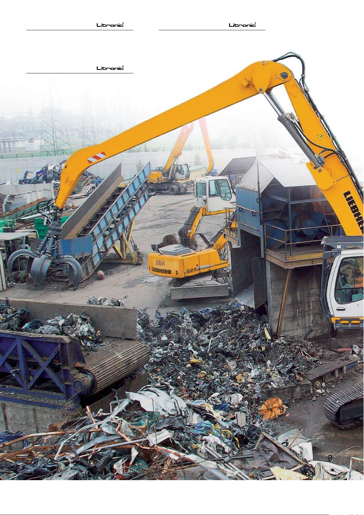
These new electric Material Handlers have been designed
to meet the specific needs of industrial handling. A wide
range of equipment and uppercarriages optimized for
long working radius provide the ideal answer to all the
demands which arise in the industry.
The performance of the kinematic chain formed from components from our in-house production, combined with the
power of the electric motor, maximize the performance
of the machine when it comes to lifting power, precision,
and speed of operation. The equipment’s performance is
enhanced by the mobility provided by the crawler undercarriage.
Comfort
Helping the operator to concentrate on his work and get
the best out of his machine is achieved by providing a
comfortable driving position, good visibility, and a highly
ergonomic layout of the controls. The new electric Material Handlers offer the same level of comfort as on the
mobile excavators (arrangement of the controls, driver’s
seat, climate control, large window areas, etc.). The electric motor system adds a further layer of comfort thanks
to the low noise emissions and absence of vibration. For
Liebherr, comfort also means ease of daily maintenance
of the machine in terms of access to the service and inspection points, so as to minimize down time.
Reliability
Backed by more than 30 years experience in the construction of electric excavators, Liebherr designed the
new ER 934 C, ER 944 C and ER 954 C with the aim of
providing top performance whatever the challenge might
be. The structure of the machine, using components from
our own manufacture for the electric drive, has been
completely rethought, and so moves away from simply
being an adaptation of a diesel-engine machine. Being
intended for key functions in the organization of industrial
sites, Liebherr electric Material Handlers provide a very
high level of reliability. The service life of the hydraulic
components has also been increased, thanks to
the smoother movement of the electric drive. The
concept of the single actuator (one single elec-
tric motor for all the hydraulic functions) allows
all the low-voltage functions to be concentrated
in a single box.
Economy
Investing in the acquisition of an electric Material Handler
is a great long-term advantage. Constant increases in the
costs of conventional energy sources are pushing up operating charges, and reducing profi t margins considerably. Environmental criteria, in particular CO2 emissions,
are also playing a constantly greater part in the choice of
power systems and working methods. With the electric
drive, Liebherr offers an economical alternative to conventional diesel-engine machines, and a solution with
real respect for the environment. Also, the excavator is
permanently available, with no need to refill. There are no
constraints (e.g. DPF or AdBlue).
ER 934 C ER 944 C ER 954 C Material Handlers
3
Page 4
ER 934 C ER 944 C ER 954 C Material Handlers
4
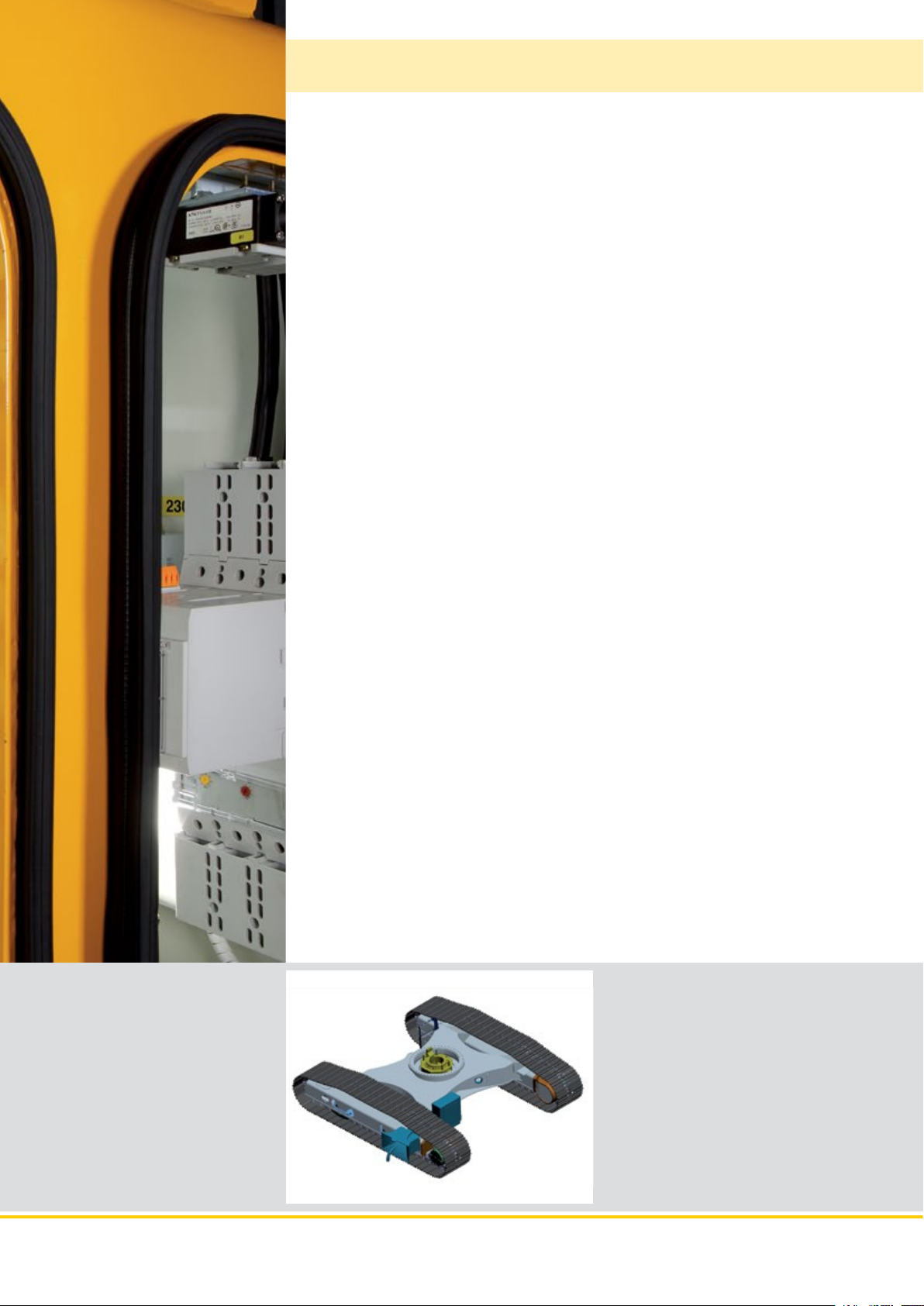
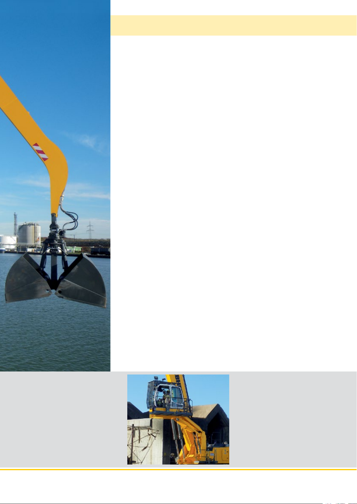
Side or rear cable opening for freely
positioning the cable on the ground
•Powersupplythroughmulticorewiring
cable entrance (funnel-shaped) especially
designed for travelling machines
•Forlongerdistancesacablereelcan
be proposed as an option
•Heavydutyconnectingboxttedonthemiddle
piece of the undercarriage with switching system
Page 5
Performance
These new electric Material Handlers have been designed to meet the specifi c
needs of industrial handling. A wide range of equipment and uppercarriages optimized for long working radius provide the ideal answer to all the demands which
arise in the industry. The performance of the kinematic chain formed from components from our in-house production, combined with the power of the electric
motor, maximize the performance of the machine when it comes to lifting power,
precision, and speed of operation. The equipment’s performance is enhanced by
the mobility provided by the crawler undercarriage.
Exceptional lift capacity
Excellent Working
Radius
Fast work cycles
Precision
Thanks to optimized kinematics and uppercarriage,
the machines offer extended reach and balance
with a better absorption of mechanical forces.
Designed for the most demanding applications, the
machines offer extended reach and lift capacity in
wide working radius.
The ER 934 C, ER 944 C and ER 954 C electric
excavators are fitted with the Liebherr Torque Control system. The hydraulic guidance system on the
excavator operates as a closed circuit, and does
not affect the speed of movement of the equipment during the working cycle. The high torque and
high oil delivery from the guide pump maximize the
excavator swing speed.
A two-pump hydraulic system allows for operating
speeds to be reached which are unequalled anywhere. Regeneration on the circuits for the equipment allows for optimization of the hydraulic power
available and minimizing response time to the operator’s commands.
The hydraulic control allows for exceptional precision - even at extended reach - contributing to the
confidence of the operator and achieving high performance as a result.
Distributor
•Fineresponseofhydrauliccontrol
for maximum working precision
•Immediateresponsetooperator‘s
commands
•Three-pumphydraulicsystem,oneof
which is a closed circuit dedicated to
uppercarriage swing
High strenght structure
•Highstrengthsteelsheetatpoints
subject to severe stress.
•Stablemountingofequipment
elements
•Exceptionalstrength,evenunder
intense loading
ER 934 C ER 944 C ER 954 C Material Handlers
5
Page 6
ER 934 C ER 944 C ER 954 C Material Handlers
6
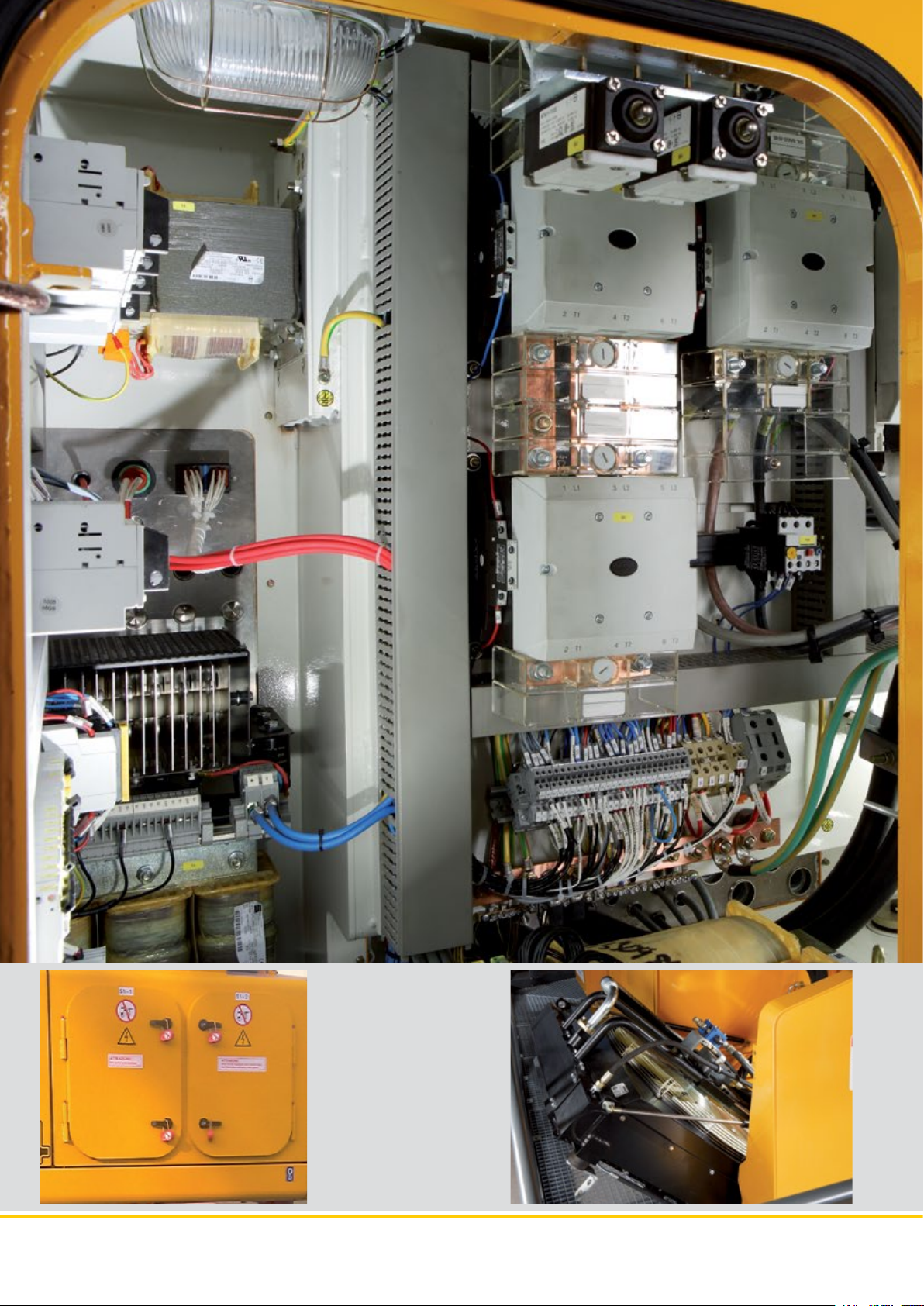
Reliability - Safety
•AutomaticPowercutoffif
the cabinet doors are opened
•Automaticpowercutoffin
the event of any anomalies
(electric motor or its bearings
overheating)
•Activesafetyon
the transformers in
the electric cabinet
•Possibletolockwithpadlock
Page 7
Reliability
Backed by more than 30 years experience in the construction of electric excavators, Liebherr designed the new ER 934 C, ER 944 C and ER 954 C with the aim of
providing top performance whatever the challenge might be. The structure of the
machine, using components from our own manufacture for the electric drive, has
been completely rethought, and so moves away from simply being an adaptation
of a diesel-engine machine. Being intended for key functions in the organization
of industrial sites, Liebherr electric Material Handlers provide a very high level of
reliability. The service life of the hydraulic components has also been increased,
thanks to the smoother movement of the electric drive. The concept of the single
actuator (one single electric motor for all the hydraulic functions) allows all the
low-voltage functions to be concentrated in a single box.
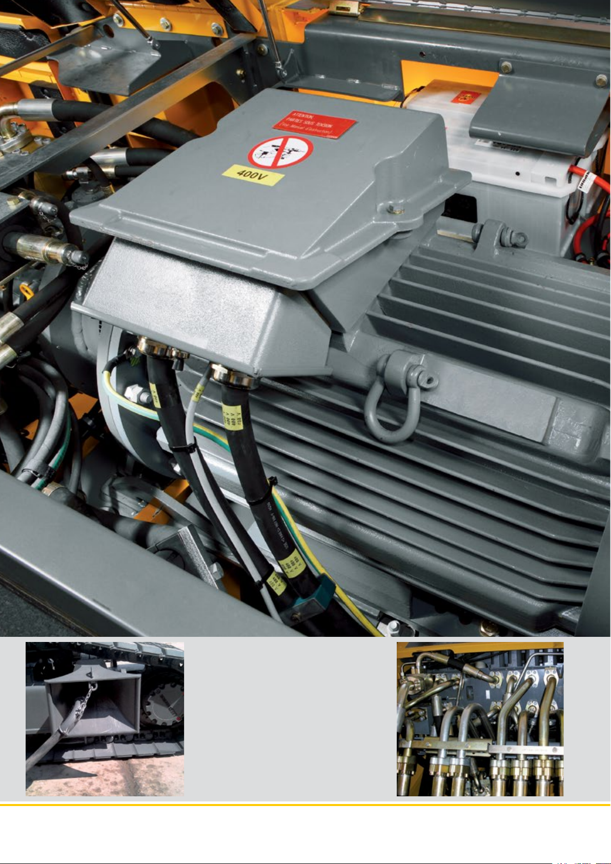
Electrical
system
Protected
electric cabinet
Electric motor
Totally integrated into the structure of the uppercarriages
and accommodated in a metal container, the electric cabinet
provides a three-fold level of protection to the components
of the electrical system:
- Mechanical (insulation from vibrations and from the possible impact of falling objects)
- Heat (maintains a constant temperature thanks to the heating resistors which prevent corrosion from condensation)
- Electrical earthing of the structure and disconnection from
current is controlled from the cab by way of a motorised
circuit-breaker.
The electric cabinet, such as the collecting pipe, provides
IP55 class protection. A filtered ventilation system which
avoids any dust penetration and, with permanent ventilation, ensures the thermal balance of all the components.
Liebherr electric excavators are equipped with motors especially designed for really tough applications. The dimensions
of the motor allow for the full power to be drawn from the
kinematic chain, and so maximises the performance of the
machine especially in the combined movements. The motor
can resist a momentary overload of up to +25 % of its rated
capacities. Protected against penetration by water and dust,
its properties correspond to protection class IP55.
The temperature of the roller bearings and other bearing
elements is constantly monitored, and, in the event of overheating, the operator is warned of malfunction on the console at the driving position.
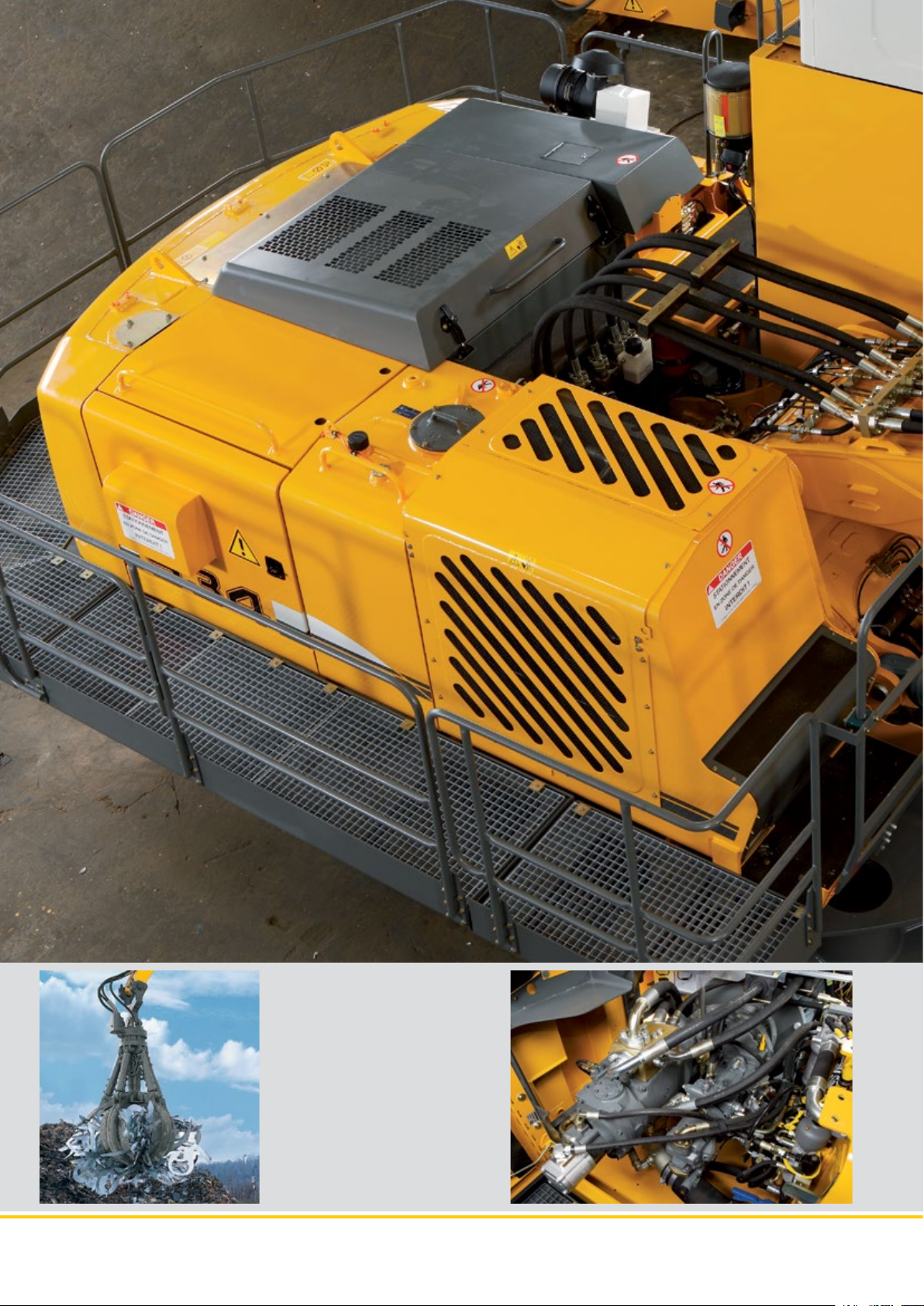
Cooling system
•Generousdimensions
for high cooling capacity
•Verticalarrangementforincreased
efficiency and minimal incursion of
foreign bodies
•Poweredbyathermostatically
regulated hydraulic motor
•Hingedtoallowforcomplete
cleaning
•Reversibleactuationofthefan
(without time limit) as option
Undercarriage
•TheundercarriagesarethoseoftheEW
or S-EW diesel machines for industrial
applications, flat or ribbed tiles
•Theundercarriagesaredesignedand
built especially for electric excavators:
- side cable opening
- armoured junction box
- electrical collecting pipe
ER 934 C ER 944 C ER 954 C Material Handlers
7
Page 8
ER 934 C ER 944 C ER 954 C Material Handlers
8
Cab with control panel
•Thecommandarrangementfor
putting the electrical system under
voltage is progressive (3 functions)
and the emergency stop button allows for the general cutting of the
electric cabinet supply
•Availableasanoptionisacutoff
system deriving from one source
point, which can be activated from
the driving position via an additional rotating joint
Page 9
Comfort
Helping the operator to concentrate on his work and get the best out of his machine is achieved by providing a comfortable driving position, good visibility, and
a highly ergonomic layout of the controls. The new electric Material Handlers
offer the same level of comfort as on the mobile excavators (arrangement of the
controls, driver’s seat, climate control, large window areas, etc.). The electric motor system adds a further layer of comfort thanks to the low noise emissions and
absence of vibration. For Liebherr, comfort also means ease of daily maintenance
of the machine in terms of access to the service and inspection points, so as to
minimize down time.
Driving position
Low noise emissions
Carbon gas emission
Mounted as standard on a fixed platform of
1,200 mm ( 2,000 mm or hydraulic platform on request), the new cab on the electric excavators
meetsallsafetystandardsinforce(24 Vsupplyin
the operator’s compartment), comfort, panoramic
visibility, and ergonomic arrangement of the controls for perfect control of the machine.
Liebherr electric excavators are really quiet in operation. Their measured acoustic level is from 4 to
5 dB lower than an equivalent diesel-engine version.
The level of noise intensity from a Liebherr electric
excavator represents less than a third of the noise
generated by a diesel-engine unit.
Zero grams of CO
emitted per tonne of product
2
handled!
Climate control entirely automatic
•Automaticclimatecontrolensuresa
level of comfort similar to a private car
•Twosensorsforprecisetemperature
regulation
•Ventilationapscanbeadjusted
at the touch of a button
•Rapiddemistinganddefrosting
of the windscreen thanks to the
«reheat“ function
Parallelogram hydraulic lift
•Improvedvisibilityoftheoperator
over his workspace
ER 934 C ER 944 C ER 954 C Material Handlers
9
Page 10
ER 934 C ER 944 C ER 954 C Material Handlers
10
Wide range of solutions
•Modulararrangement
for rapid changeover
•Liebherrquick-couplingsystem,
mechanical and hydraulic, for
efficient equipment changeover
•Quick-couplingarrangementfor
hydraulic lines (Multi-Coupler)
•Completerangeofgrapples
•Rangeofdifferentwoodgrapples
and grab buckets from Liebherr
Page 11
Economy
Investing in the acquisition of an electric Material Handler is a great long-term
advantage. Constant increases in the costs of conventional energy sources are
pushing up operating charges, and reducing profit margins considerably. Environmental criteria, in particular CO2 emissions, are also playing a constantly
greater part in the choice of power systems and working methods. With the electric drive, Liebherr offers an economical alternative to conventional diesel-engine
machines, and a solution with real respect for the environment. Also, the excavator is permanently available, with no need to refill. There are no constraints (e.g.
DPF or AdBlue).
Flexibility and versatility
Energy costs cut
Increased service life
Maximum availability
Liebherr electric Material Handlers are multi-tasking
machines. With a wide range of tools, which can be
combined with Liebherr quick-coupling systems,
they can create a degree of flexibility and versatility
which has no comparison anywhere.
The energy yield from an electric motor is greater
than that of a diesel-engine. Delivering the same kW
output in hydraulic power costs three to five times
less with an electric excavator than with a diesel-engine unit. Liebherr excavators deliver the full power
from their kinematic chain and at a lot less cost.
The smooth actuation of the electric drive and the
reliability of Liebherr hydraulic components mean
that the maintenance costs of the excavator can be
reduced considerably.
The absence of vibrations and variations in output
from a motor, which operates on a torque principle
and at constant output, means that the stress on
the kinematic chain can be reduced and the optional pre-heating of the hydraulic system allows for the
hydraulic oil to be kept at an optimum temperature
right from the start.
The costs associated with maintenance operations
are reduced to a minimum, and that also cuts downtimes. The electric motor does not require any maintenance beyond lubrication of the bearings every
3,000 hours. No filters (air, oil) to be changed and no
draining of engine oil throughout the entire service
life of the machine.
Kinematic chain made by Liebherr
•Constantprovisionofpower
for the kinematic chain
•Reducedwearofhydraulic
components
•Optimumexploitationofthehydraulic
power potential of the system
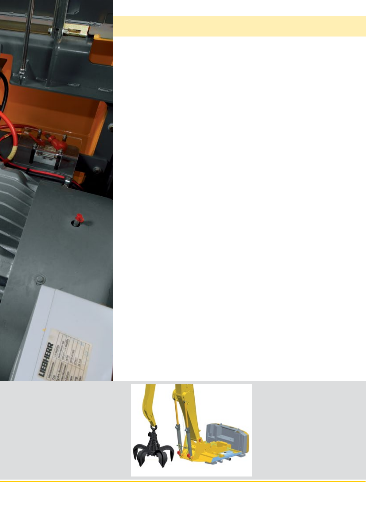
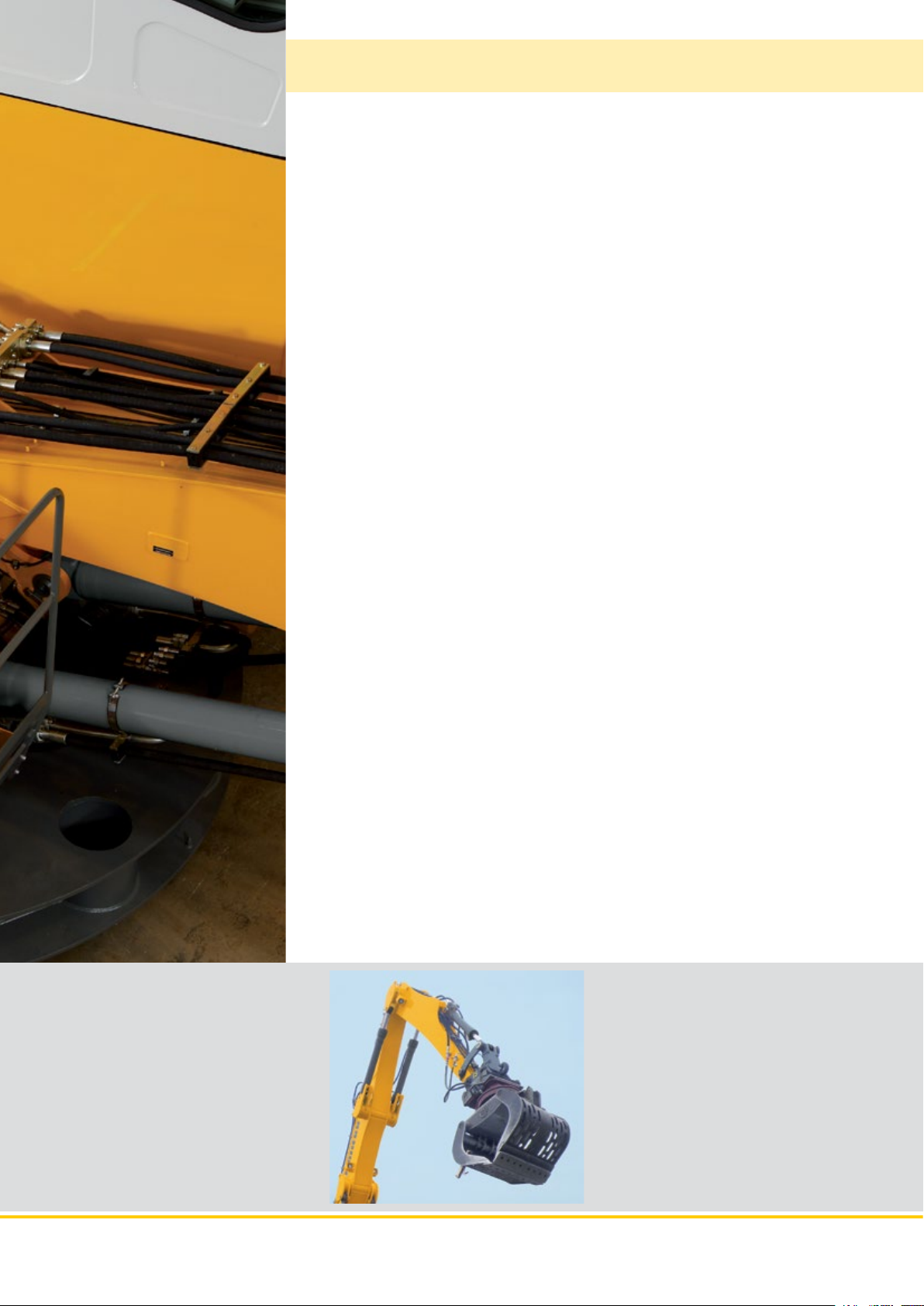
Backhoe stick with sorting grapple
•Numerouscombinationsareassociated with Liebherr’s wide range of tools
(straight and angled mono boom,
sticks and industrial sticks, etc.)
ER 934 C ER 944 C ER 954 C Material Handlers
11
Page 12

VarioLiftPlus
Variable Boom Mounting Positions for Optimized Lift Capacities
with the same working range with a different working range
Hole A
Hole B
Hole 3
Hole 2
Version 2A
2A
2A
3B
3B
3A
Kinematic variant 2A:
Increased lift capacities above ground level
Kinematic variant 3B:
Increased lift capacities below ground level
and when working at large outreach
with a different working range
Kinematic variant 3A:
Altered range curve with additional reach
depth, e.g. for unloading from ships
Hole D
Hole C
Hole 3
Hole 2
Version 3D
3D
3D
Kinematic variant 3D:
Increased lift capacities below ground level
and when working at large outreach
3C
Kinematic variant 3C:
Altered range curve with additional reach
depth, e.g. for unloading from ships
12 ER 934 C ER 944 C ER 954 C Material Handlers
Page 13

Technical Data
Electric Motor
������������������������������
Engine
934 944 954
Power rating
(as per CEI 34-1)
Rated voltage
Number of poles
Design type
Standard degree of protection
Insulation
Cooling
Heat protection for windings
Heat protection for bearings
Anti-condensation heating system resistors
������������������
���������������������
������������������
�����������������������
��������������������������
�����������������������������
induction motor dedicated definition Liebherr
160
kW (217 HP)
400 V – 50 Hz *
4
horizontal axle B35
axle height 315 mm
��
IP55
class F
IC06
200
kW (272 HP)
250
kW (340 HP)
Electric System
The 400 V electrical cabinet provides a degree of protection to IP55.
This houses the following components:
– Main contactor – remote control inside the cab
– Star/delta starter for motor
– Outlets for supplying auxiliary elements: heating, climate control
– Overheat protection devices
– Integrated heating and ventilation
– Filtered booster
– Transformers – rectifier for 24 V control circuit
– Motor protection
– Auxiliary batteries: 2 x 135 Ah/12 V: secured functions: lighting for excavator/
attachment position (option)
– Connecting inside closed panel
– Equipment: slip ring collector
power connector
embedded cable reel
Swing Drive
����������������������������
Drive by
Transmission
Swing ring
934 944 954
Swing speed
Swing torque
Holding brake
Option
����������������������
�������������������������
����������������������
����������������������
���������������������
������������������������������
hydraulic swash plate motor with integrated
brake valves
Liebherr compact planetary reduction gear
Liebherr, sealed single race ball bearing swing
ring, internal teeth
0 – 9.4 RPM 0 – 7.9 RPM 0 – 5.6 RPM
stepless stepless stepless
81.07 kNm 119 kNm 167.23 kNm
oil-bath disk brake (negative action)
pedal controlled positioning brake
Operator’s Cab
���������������������������������
Cab
Operator’s seat
Controls
Monitoring
Climate control
Noise emission
2000/14/EC 934 944 954
L
WA
�������������������
����������������������������
�������������������������
�������������������
(surround noise)
single shell concept with shaped profiles, resil-
iently mounted, sound insulated, tinted windows.
Front window can be folded away under roof,
door with sliding window
shock absorbing suspension, adjustable to
operator’s weight, 6-way adjustable seat
integrated into adjustable seat consoles
menu driven digital display of current operating
conditions. Automatic monitoring, display, warn-
ing (audible and visual signal) and saving of
machine malfunction data, such as overheating
of windings, motor bearings, or low hydraulic
oil level
standard climate control system, combined
cooler/heater, additional dust filter in the outside/
fresh air circuit
�������
101 dB(A) 103 dB(A) 105 dB(A)
ER 954 C ER 944 C ER 934 C
Hydraulic System
934 944 954
Hydraulic pump
for the attachment
Max. flow
Max. pressure
Pumpenansteuerung
Hydraulic pump
for the swing drive
Max. flow
Max. pressure
Hydraulic tank
Hydraulic system
���������������������������
Filtration
�����������������������������
Cooling
Tool Control
�����������������������
����������
���������������������
���������������
������������
����������
���������������������
���������������
��������������������
�����������������
two Liebherr swash plate pumps with variable
output
2 x 253 l/min. 2 x 305 l/min. 2 x 341 l/min.
350 bar
electro-hydraulic, with electronic regulation by
power limit, minimum pump flow at max. pres-
sure, distribution of oil to different receptor
components proportional to demand
reversible swash plate pump, in closed circuit
170 l/min. 205 l/min. 205 l/min.
370 bar
340 l 460 l 440 l
550 l 710 l 790 l
934: filter in the return circuit, with integrated fine
filter elements (5 μm)
944/954: 2 filters in the return circuit, with inte-
grated fine filter elements (5 μm)
radiator equipped with hydrostatic drive fan for
cooling the hydraulic oil and climate control
condenser
10 flow rates and pressures adjustable as option
for optional accessories
Hydraulic Controls
Power distribution
Flow summation
Closed-loop circuit
Control
Attachment and swing
Travel
Additional functions
����������������
������������
���������
�����
�������������������������
��������������
with the aid of hydraulic distributors with
integrated safety valves
to boom stick and stick
for uppercarriage swing drive mechanism
proportional by handling element in cross
operation
proportional by pedals or by lever
proportional by pedals or by toggle switch
Undercarriage
Versions
934: EW
944: S-EW
954: S-EW
Drive
Transmission
934 944 954
Travel speed
Drawbar pull max.
Track components
Track rollers/Carrier rollers
Tracks
Track pads
Digging locks
Brake valves
����������������������
�������������������
��������������������������������
�������������������
����������������������
����������������������
����������������
���������������
������������������������������
������������������������
���������������������
����������������������
�����
special material handling, extra wide gauge
special material handling, extra wide gauge,
reinforced track components
removable side frames, extra wide gauge
Liebherr swash plate motors with integrated
brake valves on both sides
Liebherr planetary reduction gears
2.8 km/h 2.8 km/h 2.6 km/h
323 kN 429 kN 478 kN
maintenance- maintenance- maintenance-
free free free
B 60 D 7 G D 7 G
9/2 10/2 13/3
sealed and greased
triple grouser
wet multi-discs (spring applied, pressure
released)
integrated into travel motor
Attachment
��������������������������������
Type
Hydraulic cylinders
�������������������������������
Pivots
Lubrication
VarioLift
������������������������
�������������������������
Plus
���������������
high-strength steel for extreme stresses. Bearings
designed for optimum distribution of stresses
Liebherr cylinders with end-of-travel shock
absorbing, fitted with guide and sealing joints
sealed, low maintenance
centralised semi-automatic Liebherr lubrication
system
variable boom mounting positions for optimized
lift capacities
* Other voltages and frequencies possible on request.
ER 934 C ER 944 C ER 954 C Material Handlers 13
Page 14

The Right Attachment
for Every Application
ER 934 C
Sorting grapple
Wood grapple
Stick 5.0 0 m
Stick 6.0 0 m
Industrial stick 6.00 m
Industrial-type straight mono boom 7.60 m
Rigid cab elevation
Industrial-t ype straight mono boom 8.60 m
Hydraulic cab elevation
Hydraulic cab elevation
+ intermediate piece
Multiple Tine
Grapple
Clamshell bucket
Industrial stick 7.50 m
Industrial-type angled mono boom 7.60 m
Industrial-type angled mono boom 8.60 m
Undercarriage
For further information please contact your Liebherr dealer.
14 ER 934 C ER 944 C ER 954 C Material Handlers
Page 15

Dimensions
W
L
U
Z
V
X
mm
A 3,225
C 3,480
D 3,240
E 3,240
H 2,615
K 1,200
L 3,848
P 1,056
Q 400
S 3,400
U 4,720
N 500 600 750
B 3,998 4,000 4,150
G 4,195 4,195 4,195
G1 4,610 4,610 4,610
Z 5,600
E = Tail radius
E
D
H
K
N
A
P
Q
S
B
G
G1
Industrial-Type Straight Mono Boom 8.60 m
and Industrial Stick m 6.00 7.50
V mm 6,700 5,600
W mm 2,800 4,200
X mm 12,200 12,050
Industrial-Type Straight Mono Boom 8.60 m
and Stick m 5.00 6.00
V mm 6,200 5,500
W mm 2,550 3,050
X mm 11,200 11,150
ER 934 C
C
E
D
W
L
U
Z
V
X
H
K
N
A
C
P
Q
S
B
G
G1
ER 934 C ER 944 C ER 954 C Material Handlers 15
Page 16

Industrial Attachment
with Industrial-Type Straight Mono Boom 8.60 m
ft
m
60
18
16
50
ER 934 C
14
40
12
10
30
8
20
6
4
10
2
0
0
-2
-10
-20
-30
-4
-6
-8
1618
14
60
50
1
2
3
4
0 m24681012
0 ft10203040
Attachment Envelope
Kinematic variant 2A
1 with industrial stick 6.00 m
2 with industrial stick 7.50 m
3 with industrial stick 6.00 m and grapple model GM 65
4 with industrial stick 7.50 m and grapple model GM 65
Operating Weight
and Ground Pressure
Operating weight includes basic machine with rigid cab elevation
1.20 m, counterweight 7.5 t, industrial-type straight mono boom
8.60 m, industrial stick 6.00 m and grapple model GM 65 with
5 semi-closed tines 0.60 m
Undercarriage EW
Pad width mm 600 750
Weight kg 38,050 38,550
Ground pressure kg/cm
Operating weight includes basic machine with rigid cab elevation
1.20 m, counterweight 7.5 t, industrial-type straight mono boom
8.60 m, industrial stick 7.50 m and grapple model GM 65 with
5 semi-closed tines 0.60 m
Undercarriage EW
Pad width mm 600 750
Weight kg 38,100 38,600
Ground pressure kg/cm
3
(1,415 kg).
3
(1,415 kg).
2
0.83 0.67
2
0.83 0.67
16 ER 934 C ER 944 C ER 954 C Material Handlers
Page 17

Lift Capacities
with Industrial-Type Straight Mono Boom 8.60 m
Industrial Stick 6.00 m (Variant 2A)
3.0 m 4.5 m 6.0 m 7.5 m 9.0 m 10.5 m 12.0 m 13.5 m 15.0 m
Under m carriage m
16.5 EW
15.0 EW
13.5 EW
12.0 EW
10.5 EW
9.0 EW
7.5 EW
6.0 EW
4.5 EW
3.0 EW
1.5 EW
0 EW
– 1.5 EW
– 3.0 EW
– 4.5 EW
9.9* 9.9* 7.7* 7.7* 6.0
9.6* 9.6* 8.1* 8.1* 6.2* 6.2* 8.5
9.3* 9.3* 8.0* 8.0* 5.5* 5.5* 10.2
9.2* 9.2* 8.1* 8.1* 6.3 6.8 5.2* 5.2* 11.5
9.3* 9.3* 8.1* 8.1* 6.3 6.8 5.0 5.4 4.6 4.9* 12.5
11.3* 11.3* 9.5* 9.5* 8.0 8.2* 6.2 6.8 5.0 5.4 4.1 4.5 13.2
12.3* 12.3* 11.9* 11.9* 9.8* 9.8* 7.8 8.4* 6.1 6.6 4.9 5.3 4.0 4.3 3.8 4.2 13.7
24.9* 24.9* 16.7* 16.7* 12.6* 12.6* 9.9 10.2* 7.5 8.1 5.9 6.4 4.8 5.2 3.9 4.3 3.6 4.0 14.1
17.9* 17.9* 12.9 13.2* 9.3 10.2 7.1 7.8 5.7 6.2 4.6 5.1 3.9 4.2 3.5 3.9 14.3
5.8* 5.8* 12.0 13.2* 8.8 9.7 6.8 7.5 5.5 6.0 4.5 4.9 3.8 4.1 3.5 3.8 14.3
4.9* 4.9* 11.4 12.5* 8.4 9.2 6.5 7.2 5.3 5.8 4.4 4.8 3.7 4.1 3.5 3.7* 14.1
5.6* 5.6* 11.1* 11.1* 8.1 9.0 6.4 7.0 5.2 5.7 4.3 4.8 3.6* 3.6* 3.5* 3.5* 13.5
9.0* 9.0* 7.7* 7.7* 6.3 6.4* 5.1 5.2* 4.1* 4.1* 11.9
ER 934 C
Industrial Stick 7.50 m (Variant 2A)
3.0 m 4.5 m 6.0 m 7.5 m 9.0 m 10.5 m 12.0 m 13.5 m 15.0 m
Under m carriage m
16.5 EW
15.0 EW
13.5 EW
12.0 EW
10.5 EW
9.0 EW
7.5 EW
6.0 EW
4.5 EW
3.0 EW
1.5 EW
0 EW
– 1.5 EW
– 3.0 EW
– 4.5 EW
Height Can be slewed through 360° In longitudinal position of undercarriage Max. reach * Limited by hydr. capacity
The lift capacities are stated in metric tonnes (t) on the lifting gear’s stick tip, and can be lifted 360° on firm, level supporting surface. Capacities
are valid for 600 mm wide triple grouser pads. Indicated loads are based on ISO 10567 standard and do not exceed 75 % of tipping or 87 % of
hydraulic capacity (indicated via *). Lifting capacity of the excavator is limited by machine stability, hydraulic capacity and maximum permissible
load of the load hook.
According to European Standard, EN 474-5: In the European Union excavators have to be equipped with an overload warning device, a load
diagram and automatic safety check valves on hoist cylinders and stick cylinder(s), when they are used for lifting operations which require the use
of lifting accessories.
6.8* 6.8* 6.5* 6.5* 6.2
7.0* 7.0* 5.1* 5.1* 9.0
7.8* 7.8* 6.8* 6.8* 5.1* 5.1* 4.5* 4.5* 10.8
7.5* 7.5* 6.6* 6.6* 4.6* 4.6* 4.1* 4.1* 12.2
7.5* 7.5* 6.6 6.7* 5.2 5.6 3.9* 3.9* 13.3
7.5* 7.5* 6.6 6.7* 5.2 5.6 4.2 4.5 3.7 3.8* 14.2
8.7* 8.7* 7.6* 7.6* 6.5 6.8* 5.1 5.6 4.1 4.5 3.4 3.7* 14.8
9.1* 9.1* 7.9* 7.9* 6.3 6.8 5.0 5.5 4.1 4.5 3.3 3.7 3.2 3.5 15.3
10.7* 10.7* 9.5* 9.5* 7.8 8.1* 6.1 6.6 4.9 5.3 4.0 4.4 3.3 3.6 3.1 3.4 15.6
19.2* 19.2* 16.4* 16.4* 12.4* 12.4* 9.8 10.0* 7.4 8.1 5.8 6.4 4.7 5.1 3.9 4.3 3.2 3.6 3.0 3.3 15.7
2.7* 2.7* 17.6* 17.6* 12.7 13.0* 9.1 10.0 7.0 7.7 5.6 6.1 4.5 5.0 3.8 4.1 3.2 3.5 2.9 3.2 15.8
2.2* 2.2* 7.2* 7.2* 11.8 13.0* 8.6 9.5 6.6 7.3 5.3 5.8 4.4 4.8 3.7 4.0 3.1 3.4 2.9 3.2* 15.6
2.9* 2.9* 6.1* 6.1* 11.2 12.3* 8.1 9.0 6.3 7.0 5.1 5.6 4.2 4.7 3.6 4.0 3.1 3.3* 2.9* 2.9* 15.3
6.4* 6.4* 10.8 10.9* 7.9 8.7 6.1 6.8 5.0 5.5 4.2 4.6 3.5 3.8* 3.2* 3.2* 14.2
8.9* 8.9* 7.5* 7.5* 6.1 6.2* 4.9 5.1* 4.0* 4.0* 3.7* 3.7* 12.3
ER 934 C ER 944 C ER 954 C Material Handlers 17
Page 18

Industrial Attachment
with Industrial-Type Straight Mono Boom 8.60 m
ft
m
60
18
55
16
ER 934 C
50
14
45
40
12
35
10
30
8
25
20
6
15
4
10
2
5
0
0
-5
-2
-10
-4
-15
-20
-6
60 5152535455 5
14
1618
50
1
2
0 m24681012
0 f t10203 040
Attachment Envelope
Kinematic variant 2A
1 with stick 5.00 m
2 with stick 6.00 m
3 with stick 5.00 m and sorting grapple SG 30
4 with stick 6.00 m and sorting grapple SG 30
Operating Weight
and Ground Pressure
Operating weight includes basic machine with rigid cab elevation
1.20 m, counterweight 7.5 t, industrial-type straight mono boom
8.60 m, stick 5.00 m and sorting grapple SG 30 with tines 0.80 m
(1,730 kg).
Undercarriage EW
Pad width mm 600 750
Weight kg 38,750 39,250
Ground pressure kg/cm
Operating weight includes basic machine with rigid cab elevation
1.20 m, counterweight 7.5 t, industrial-type straight mono boom
8.60 m, stick 6.00 m and sorting grapple SG 30 with tines 0.80 m
(1,730 kg).
Undercarriage EW
Pad width mm 600 750
Weight kg 38,950 39,450
Ground pressure kg/cm
2
0.84 0.68
2
0.84 0.68
3
3
18 ER 934 C ER 944 C ER 954 C Material Handlers
Page 19

Lift Capacities
with Industrial-Type Straight Mono Boom 8.60 m
Stick 5.00 m (Variant 2A)
3.0 m 4.5 m 6.0 m 7.5 m 9.0 m 10.5 m 12.0 m 13.5 m 15.0 m
Under m carriage m
16.5 EW
15.0 EW
13.5 EW
12.0 EW
10.5 EW
9.0 EW
7.5 EW
6.0 EW
4.5 EW
3.0 EW
1.5 EW
0 EW
– 1.5 EW
– 3.0 EW
– 4.5 EW
13.4* 13.4* 12.3* 12.3* 3.5
12.3* 12.3* 10.5* 10.5* 8.1* 8.1* 7.0
11.2* 11.2* 9.5* 9.5* 7.1* 7.1* 6.9* 6.9* 9.0
11.1* 11.1* 9.3* 9.3* 7.6 8.1* 5.7 6.2 10.5
11.2* 11.2* 9.4* 9.4* 7.6 8.1* 5.8 6.3 4.8 5.2 11.5
13.1* 13.1* 11.6* 11.6* 9.6* 9.6* 7.4 8.1 5.7 6.2 4.5 4.9 4.2 4.6 12.3
12.3* 12.3* 15.9* 15.9* 12.2* 12.2* 9.7 9.9* 7.2 7.9 5.6 6.1 4.4 4.9 3.9 4.3 12.9
17.2* 17.2* 12.7* 12.7* 9.2 10.1 6.9 7.6 5.4 5.9 4.3 4.8 3.6 4.0 13.2
3.3* 3.3* 12.0 12.9* 8.6 9.5 6.6 7.3 5.2 5.7 4.2 4.7 3.5 3.9 13.4
1.6* 1.6* 11.3 12.5* 8.2 9.1 6.3 7.0 5.0 5.6 4.1 4.6 3.5 3.8* 13.4
2.5* 2.5* 9.8* 9.8* 7.9 8.8 6.1 6.8 4.9 5.4 4.1 4.5 3.3* 3.3* 13.3
9.2* 9.2* 7.7 7.9* 6.0 6.5* 4.8 5.2* 3.9* 3.9* 3.6* 3.6* 12.2
ER 934 C
Stick 6.00 m (Variant 2A)
3.0 m 4.5 m 6.0 m 7.5 m 9.0 m 10.5 m 12.0 m 13.5 m 15.0 m
Under m carriage m
16.5 EW
15.0 EW
13.5 EW
12.0 EW
10.5 EW
9.0 EW
7.5 EW
6.0 EW
4.5 EW
3.0 EW
1.5 EW
0 EW
– 1.5 EW
– 3.0 EW
– 4.5 EW
Height Can be slewed through 360° In longitudinal position of undercarriage Max. reach * Limited by hydr. capacity
The lift capacities are stated in metric tonnes (t) on the lifting gear’s stick tip, and can be lifted 360° on firm, level supporting surface. Capacities
are valid for 600 mm wide triple grouser pads. Indicated loads are based on ISO 10567 standard and do not exceed 75 % of tipping or 87 % of
hydraulic capacity (indicated via *). Lifting capacity of the excavator is limited by machine stability, hydraulic capacity and maximum permissible
load of the load hook.
According to European Standard, EN 474-5: In the European Union excavators have to be equipped with an overload warning device, a load
diagram and automatic safety check valves on hoist cylinders and stick cylinder(s), when they are used for lifting operations which require the use
of lifting accessories.
10.4* 10.4* 8.2* 8.2* 7.6* 7.6* 6.3
9.8* 9.8* 8.4* 8.4* 6.0* 6.0* 8.7
8.9* 8.9* 7.8 7.8* 5.3* 5.3* 10.4
8.8* 8.8* 7.7* 7.7* 5.9 6.5 4.7 4.9* 11.7
8.9* 8.9* 7.7* 7.7* 5.9 6.5 4.6 5.0 4.1 4.5 12.6
10.8* 10.8* 9.1* 9.1* 7.6 7.8* 5.8 6.4 4.6 5.0 3.6 4.0 13.4
10.5* 10.5* 11.5* 11.5* 9.4* 9.4* 7.4 7.9* 5.7 6.2 4.5 4.9 3.6 3.9 3.4 3.7 13.9
15.7* 15.7* 16.2* 16.2* 12.2* 12.2* 9.5 9.7* 7.1 7.7 5.5 6.0 4.4 4.8 3.5 3.9 3.2 3.5 14.2
17.1* 17.1* 12.5 12.7* 8.9 9.8 6.7 7.4 5.3 5.8 4.2 4.7 3.4 3.8 3.1 3.4 14.4
4.1* 4.1* 11.5 12.7* 8.3 9.2 6.4 7.0 5.0 5.6 4.1 4.5 3.4 3.7 3.0 3.4 14.4
3.6* 3.6* 10.9 11.9* 7.9 8.8 6.1 6.7 4.9 5.4 4.0 4.4 3.3 3.7 3.0* 3.0* 14.3
4.5* 4.5* 10.5* 10.5* 7.6 8.5 5.9 6.5 4.7 5.2 3.9 4.3 3.1* 3.1* 3.0* 3.0* 13.5
8.4* 8.4* 7.1* 7.1* 5.8 5.9* 4.7 4.7* 3.6* 3.6* 11.9
ER 934 C ER 944 C ER 954 C Material Handlers 19
Page 20

The Right Attachment
for Every Application
Industrial-type straight mono boom 8.50 m
ER 944 C
Sorting
grapple
Industrial stick 5.80 m
Stick 6.00 m
Industrial-t ype straight mono boom 9.50 m
Rigid cab elevation
Wood
grapple
Mutiple tine
grapple
Clamshell
bucket
Industrial stick 7.30 m
Industrial stick 8.80 m
Industrial-type angled mono boom 7.50 m
Hydraulic cab elevation
Hydraulic cab elevation
+ intermediate piece
For further information please contact your Liebherr dealer.
20 ER 934 C ER 944 C ER 954 C Material Handlers
Industrial-type angled mono boom 9.50 m
Undercarriage
Page 21

Dimensions
W
V
X
mm
A 3,070
C 3,630
D 3,605
E 3,605
H 3,050
K 1,320
L 4,400
P 1,170
Q 475
S 3,800
U 5,360
N 500 600 750
B 4,412 4,412 4,550
G 4,620 4,620 4,620
G1 5,025 5,025 5,025
Z 6,300
E = Tail radius
E
D
H
K
L
U
Z
N
A
Q
S
B
G
G1
Industrial-Type Straight Mono Boom 9.50 m
and Industrial Stick m 7.30 8.80
V mm 6,700 5,650
W mm 3,350 4,650
X mm 13,600 13,400
Industrial-Type Angled Mono Boom 9.50 m
and Industrial Stick m 7.30
V mm 6,400
W mm 3,600
X mm 13,500
C
P
ER 944 C
E
D
W
L
U
Z
V
X
These dimensions are stated with cab carrier. This assembly is only valid for transportation.
A
C
H
K
Q
N
S
B
G
G1
P
ER 934 C ER 944 C ER 954 C Material Handlers 21
Page 22

Industrial Attachment
with Industrial-Type Straight Mono Boom 9.50 m
mft
20
65
19
60
18
17
55
16
50
15
14
45
13
40
12
11
35
10
ER 944 C
30
9
8
25
7
20
6
5
15
4
10
3
2
5
1
0
0
-1
-5
-2
-3
-10
-4
-15
-20
-25
-30
-5
-6
-7
-8
-9
-10
1
3
2
4
01
234567891011121314151617 181920
0mft5101520253045 4055 5065 60 35
Attachment Envelope
Kinematic variant 2A
1 with industrial stick 7.30 m
2 with industrial stick 7.30 m and grapple model GM 70C
3 with industrial stick 8.80 m
4 with industrial stick 8.80 m and grapple model GM 70C
Operating Weight
and Ground Pressure
Operating weight includes basic machine with rigid cab elevation
1.20 m, counterweight 11.0 t, industrial-type straight mono boom
9.50 m, industrial stick 7.30 m and grapple model GM 70C with
5 semi-closed tines 0.80 m
Undercarriage S-EW
Pad width mm 600 750
Weight kg 52,050 53,400
Ground pressure kg/cm
Operating weight includes basic machine with rigid cab elevation
1.20 m, counterweight 11.0 t, industrial-type straight mono boom
9.50 m, industrial stick 8.80 m and grapple model GM 70C with
5 semi-closed tines 0.80 m
Undercarriage S-EW
Pad width mm 600 750
Weight kg 52,400 53,750
Ground pressure kg/cm
3
(1,705 kg).
3
(1,705 kg).
2
0.99 0.81
2
0.99 0.81
22 ER 934 C ER 944 C ER 954 C Material Handlers
Page 23

Lift Capacities
with Industrial-Type Straight Mono Boom 9.50 m
Industrial Stick 7.30 m (Variant 2A)
3.0 m 4.5 m 6.0 m 7.5 m 9.0 m 10.5 m 12.0 m 13.5 m 15.0 m 16.5 m
Under m
carriage
S-EW
19.5
S-EW
18.0
S-EW
16.5
S-EW
15.0
S-EW
13.5
S-EW
12.0
S-EW
10.5
S-EW
9.0
S-EW
7.5
S-EW
6.0
S-EW
4.5
S-EW
3.0
S-EW
1.5
S-EW
0
S-EW
– 1.5
S-EW
– 3.0
S-EW
– 4.5
S-EW
– 6.0
S-EW
– 7.5
m
12.5* 12.5* 12.5* 12.5* 4.5
12.3* 12.3* 10.3* 10.3* 9.1* 9.1* 8.1
11.8* 11.8* 10.3* 10.3* 7.9* 7.9* 10.3
11.5* 11.5* 10.1* 10.1* 9.0* 9.0* 7.2* 7.2* 11.9
11.4* 11.4* 10.0* 10.0* 8.9* 8.9* 7.8 7.9* 6.5 6.8* 13.2
11.5* 11.5* 10.0* 10.0* 8.9* 8.9* 7.9 7.9* 6.3 7.0 5.7 6.4 14.1
11.7* 11.7* 10.1* 10.1* 8.9* 8.9* 7.8 7.9* 6.3 7.0 5.1 5.8 14.9
14.2* 14.2* 12.0* 12.0* 10.3* 10.3* 9.0* 9.0* 7.6 8.0* 6.2 6.9 5.0 5.7 4.7 5.3 15.5
13.9* 13.9* 15.3* 15.3* 12.5* 12.5* 10.6* 10.6* 9.1* 9.1* 7.4 8.0* 6.0 6.8 5.0 5.6 4.4 5.0 15.9
24.1* 24.1* 21.5* 21.5* 16.2* 16.2* 13.0* 13.0* 10.8* 10.8* 8.9 9.2* 7.1 8.0* 5.9 6.6 4.9 5.5 4.2 4.8 16.2
22.8* 22.8* 16.8* 16.8* 13.3* 13.3* 10.7 10.9* 8.5 9.2* 6.9 7.7 5.7 6.4 4.8 5.4 4.1 4.6* 16.3
7.3* 7.3* 16.7* 16.7* 13.1 13.2* 10.1 10.8* 8.1 9.1* 6.6 7.5 5.5 6.2 4.7 5.3 4.1 4.2* 16.3
2.0* 2.0* 6.2* 6.2* 15.9* 15.9* 12.4 12.7* 9.6 10.4* 7.7 8.7* 6.4 7.2 5.4 6.1 4.6 4.9* 3.7* 3.7* 16.1
6.9* 6.9* 13.7* 13.7* 11.6* 11.6* 9.2 9.7* 7.5 8.1* 6.2 6.7* 5.2 5.5* 4.2* 4.2* 3.3* 3.3* 15.8
11.8* 11.8* 10.1* 10.1* 8.5* 8.5* 7.1* 7.1* 5.8* 5.8* 4.6* 4.6* 3.6* 3.6* 14.5
8.0* 8.0* 6.8* 6.8* 5.7* 5.7* 4.6* 4.6* 12.0
ER 944 C
Industrial Stick 8.80 m (Variant 2A)
3.0 m 4.5 m 6.0 m 7.5 m 9.0 m 10.5 m 12.0 m 13.5 m 15.0 m 16.5 m
Under m
carriage
S-EW
19.5
S-EW
18.0
S-EW
16.5
S-EW
15.0
S-EW
13.5
S-EW
12.0
S-EW
10.5
S-EW
9.0
S-EW
7.5
S-EW
6.0
S-EW
4.5
S-EW
3.0
S-EW
1.5
S-EW
0
S-EW
– 1.5
S-EW
– 3.0
S-EW
– 4.5
S-EW
– 6.0
S-EW
– 7.5
m
11.2* 11.2* 11.1* 11.1* 4.6
9.2* 9.2* 7.8* 7.8* 8.4
9.1* 9.1* 7.1* 7.1* 6.6* 6.6* 10.8
9.5* 9.5* 8.5* 8.5* 7.0* 7.0* 6.0* 6.0* 12.5
9.3* 9.3* 8.4* 8.4* 7.6* 7.6* 6.4* 6.4* 5.6* 5.6* 13.9
9.2* 9.2* 8.3* 8.3* 7.5* 7.5* 6.6 6.8* 5.3 5.3* 14.9
9.3* 9.3* 8.3* 8.3* 7.5* 7.5* 6.6 6.8* 5.3 6.0 4.7 5.2* 15.8
9.4* 9.4* 8.4* 8.4* 7.5* 7.5* 6.6 6.8* 5.3 6.0 4.3 4.9 4.3 4.9 16.5
9.6* 9.6* 8.5* 8.5* 7.6* 7.6* 6.4 6.8* 5.2 5.9 4.3 4.9 4.0 4.5 17.0
11.6* 11.6* 9.9* 9.9* 8.7* 8.7* 7.7* 7.7* 6.3 6.8* 5.1 5.8 4.2 4.8 3.8 4.3 17.4
12.9* 12.9* 12.2* 12.2* 10.3* 10.3* 8.9* 8.9* 7.4 7.7* 6.0 6.8 5.0 5.6 4.2 4.7 3.6 4.1 17.7
18.5* 18.5* 21.2* 21.2* 15.9* 15.9* 12.7* 12.7* 10.5* 10.5* 8.8 9.0* 7.1 7.8* 5.8 6.6 4.8 5.5 4.1 4.6 3.5 4.0* 17.8
3.7* 3.7* 22.4* 22.4* 16.5* 16.5* 13.0* 13.0* 10.5 10.7* 8.3 9.0* 6.7 7.6 5.6 6.3 4.7 5.3 4.0 4.5 3.5 3.7* 17.8
2.9* 2.9* 9.1* 9.1* 16.4* 16.4* 12.9 12.9* 9.9 10.5* 7.9 8.8* 6.4 7.3 5.4 6.1 4.5 5.2 3.9 4.4* 3.3* 3.3* 17.6
3.7* 3.7* 7.7* 7.7* 15.5* 15.5* 12.1 12.3* 9.3 10.1* 7.5 8.4* 6.2 7.0 5.2 5.9 4.4 4.9* 3.8* 3.8* 2.9* 2.9* 17.3
4.9* 4.9* 8.0* 8.0* 13.9* 13.9* 11.3* 11.3* 8.9 9.3* 7.2 7.8* 6.0 6.5* 5.0 5.4* 4.3* 4.3* 2.9* 2.9* 2.9* 2.9* 16.5
8.9* 8.9* 11.7* 11.7* 9.8* 9.8* 8.1* 8.1* 6.8* 6.8* 5.6* 5.6* 4.5* 4.5* 3.3* 3.3* 3.2* 3.2* 15.1
7.7* 7.7* 6.5* 6.5* 5.4* 5.4* 4.4* 4.4* 4.2* 4.2* 12.2
Height Can be slewed through 360° In longitudinal position of undercarriage Max. reach * Limited by hydr. capacity
The lift capacities are stated in metric tonnes (t) on the lifting gear’s stick tip, and can be lifted 360° on firm, level supporting surface. Capacities
are valid for 600 mm wide triple grouser pads. Indicated loads are based on ISO 10567 standard and do not exceed 75 % of tipping or 87 % of
hydraulic capacity (indicated via *). Lifting capacity of the excavator is limited by machine stability, hydraulic capacity and maximum permissible
load of the load hook.
According to European Standard, EN 474-5: In the European Union excavators have to be equipped with an overload warning device, a load
diagram and automatic safety check valves on hoist cylinders and stick cylinder(s), when they are used for lifting operations which require the use
of lifting accessories.
ER 934 C ER 944 C ER 954 C Material Handlers 23
Page 24

Industrial Attachment
with Industrial-Type Angled Mono Boom 9.50 m
mft
17
55
16
50
15
14
45
13
40
12
11
35
10
30
9
8
25
ER 944 C
-10
-15
-20
-25
-30
-35
7
20
6
5
15
4
10
3
2
5
1
0
0
-1
-5
-2
-3
-4
-5
-6
-7
-8
-9
-10
-11
1
3
2
4
1011121314151617 18
23456789
01
0mft5101520253045 4 05560 50 35
Attachment Envelope
Kinematic variants 3C/3D
1 with industrial stick 7.30 m (3D)
2 with industrial stick 7.30 m and grapple model GM 70C (3D)
3 with industrial stick 7.30 m (3C)
4 with industrial stick 7.30 m and grapple model GM 70C (3C)
Operating Weight
and Ground Pressure
Operating weight includes basic machine with rigid cab elevation
1.20 m, counterweight 11.0 t, industrial-type angled mono boom
9.50 m, industrial stick 7.30 m and grapple model GM 70C with
5 semi-closed tines 0.80 m
Undercarriage S-EW
Pad width mm 600 750
Weight kg 52,250 53,600
Ground pressure kg/cm
3
(1,705 kg).
2
0.99 0.81
24 ER 934 C ER 944 C ER 954 C Material Handlers
Page 25

Lift Capacities
with Industrial-Type Angled Mono Boom 9.50 m
Industrial Stick 7.30 m (Variant 3C)
3.0 m 4.5 m 6.0 m 7.5 m 9.0 m 10.5 m 12.0 m 13.5 m 15.0 m 16.5 m
Under m
carriage
S-EW
19.5
S-EW
18.0
S-EW
16.5
S-EW
15.0
S-EW
13.5
S-EW
12.0
S-EW
10.5
S-EW
9.0
S-EW
7.5
S-EW
6.0
S-EW
4.5
S-EW
3.0
S-EW
1.5
S-EW
0
S-EW
– 1.5
S-EW
– 3.0
S-EW
– 4.5
S-EW
– 6.0
S-EW
– 7.5
m
5.9* 5.9* 11.5
5.6* 5.6* 5.7* 5.7* 12.8
5.6* 5.6* 5.5* 5.5* 5.5* 5.5* 13.7
5.9* 5.9* 5.7* 5.7* 5.5* 5.5* 5.5* 5.5* 14.5
6.2* 6.2* 5.9* 5.9* 5.7* 5.7* 5.1 5.5* 5.1 5.5* 15.1
7.3* 7.3* 6.6* 6.6* 6.2* 6.2* 5.8* 5.8* 5.0 5.6* 4.7 5.3 15.5
11.1* 11.1* 9.2* 9.2* 8.0* 8.0* 7.2* 7.2* 6.5* 6.5* 5.9 6.1* 4.9 5.6 4.5 5.1 15.8
4.3* 4.3* 18.5* 18.5* 13.2* 13.2* 10.5* 10.5* 8.8* 8.8* 7.7* 7.7* 6.9 6.9* 5.7 6.4* 4.8 5.4 4.3 4.9 15.9
3.1* 3.1* 9.8* 9.8* 15.1* 15.1* 11.7* 11.7* 9.6* 9.6* 8.1 8.3* 6.6 7.3* 5.5 6.3 4.6 5.3 4.2 4.8 15.9
4.2* 4.2* 8.3* 8.3* 16.4* 16.4* 12.3 12.6* 9.6 10.3* 7.7 8.7* 6.4 7.2 5.3 6.1 4.5 5.2 4.2 4.8 15.7
5.6* 5.6* 8.7* 8.7* 15.0* 15.0* 11.8 13.3* 9.2 10.5 7.4 8.5 6.1 7.0 5.2 5.9 4.4 5.1 4.3 4.9 15.3
7.0* 7.0* 9.6* 9.6* 14.6* 14.6* 11.5 13.3 8.9 10.2 7.2 8.3 6.0 6.9 5.1 5.8 4.5 5.1 14.9
10.6* 10.6* 15.1* 15.1* 11.4 13.2 8.8 10.1 7.1 8.2 5.9 6.8 5.1 5.8 4.8 5.5 14.2
16.0 16.1* 11.4 13.2* 8.8 10.1 7.1 8.2 6.0 6.8 5.2 6.0 13.3
8.9 10.2* 7.6 8.7 10.2
ER 944 C
Industrial Stick 7.30 m (Variant 3D)
3.0 m 4.5 m 6.0 m 7.5 m 9.0 m 10.5 m 12.0 m 13.5 m 15.0 m 16.5 m
Under m
carriage
S-EW
19.5
S-EW
18.0
S-EW
16.5
S-EW
15.0
S-EW
13.5
S-EW
12.0
S-EW
10.5
S-EW
9.0
S-EW
7.5
S-EW
6.0
S-EW
4.5
S-EW
3.0
S-EW
1.5
S-EW
0
S-EW
– 1.5
S-EW
– 3.0
S-EW
– 4.5
S-EW
– 6.0
S-EW
– 7.5
m
7.6* 7.6* 7.3* 7.3* 9.8
7.2* 7.2* 6.9* 6.9* 6.7* 6.7* 11.5
6.7* 6.7* 6.5* 6.5* 6.4* 6.4* 12.8
7.1* 7.1* 6.7* 6.7* 6.4* 6.4* 6.2* 6.2* 6.2* 6.2* 13.7
7.4* 7.4* 6.9* 6.9* 6.5* 6.5* 6.2* 6.2* 5.5 6.0* 14.5
8.7* 8.7* 7.8* 7.8* 7.2* 7.2* 6.7* 6.7* 6.3* 6.3* 5.1 5.8 5.0 5.7 15.1
11.1* 11.1* 9.5* 9.5* 8.4* 8.4* 7.6* 7.6* 6.9* 6.9* 6.1 6.4* 5.0 5.7 4.7 5.3 15.5
25.8* 25.8* 17.0* 17.0* 12.9* 12.9* 10.6* 10.6* 9.1* 9.1* 8.0* 8.0* 7.2* 7.2* 5.9 6.6* 4.9 5.6 4.5 5.1 15.8
4.3* 4.3* 20.5* 20.5* 14.8* 14.8* 11.7* 11.7* 9.8* 9.8* 8.5* 8.5* 6.9 7.5* 5.7 6.5 4.8 5.4 4.3 4.9 15.9
3.1* 3.1* 9.8* 9.8* 16.3* 16.3* 12.6* 12.6* 10.1 10.4* 8.1 8.9* 6.6 7.5 5.5 6.3 4.6 5.3 4.2 4.8 15.9
4.2* 4.2* 8.3* 8.3* 17.0 17.2* 12.3 13.3* 9.6 10.9* 7.7 8.8 6.3 7.2 5.3 6.1 4.5 5.2 4.2 4.8 15.7
5.6* 5.6* 8.7* 8.7* 15.0* 15.0* 11.8 13.6 9.2 10.5 7.4 8.5 6.1 7.0 5.2 5.9 4.4 5.1 4.3 4.9 15.3
9.6* 9.6* 14.6* 14.6* 11.5 13.3 8.9 10.2 7.2 8.3 6.0 6.9 5.1 5.8 4.5 5.1 14.9
15.1* 15.1* 11.4 13.2 8.8 10.1 7.1 8.2 5.9 6.8 5.1 5.8 4.8 5.5 14.1
7.5 8.6 10.1
Height Can be slewed through 360° In longitudinal position of undercarriage Max. reach * Limited by hydr. capacity
The lift capacities are stated in metric tonnes (t) on the lifting gear’s stick tip, and can be lifted 360° on firm, level supporting surface. Capacities
are valid for 600 mm wide triple grouser pads. Indicated loads are based on ISO 10567 standard and do not exceed 75 % of tipping or 87 % of
hydraulic capacity (indicated via *). Lifting capacity of the excavator is limited by machine stability, hydraulic capacity and maximum permissible
load of the load hook.
According to European Standard, EN 474-5: In the European Union excavators have to be equipped with an overload warning device, a load
diagram and automatic safety check valves on hoist cylinders and stick cylinder(s), when they are used for lifting operations which require the use
of lifting accessories.
ER 934 C ER 944 C ER 954 C Material Handlers 25
Page 26

The Right Attachment
for Every Application
Industrial-type straight mono boom 8.50 m
ER 954 C
Mutiple tine
Sorting
grapple
Wood
grapple
grapple
Stick 7.00 m
Industrial stick 7.80 m
Industrial stick 9.00 m
Rigid cab elevation
Industrial-t ype straight mono boom 10.50 m
Hydraulic cab elevation
Industrial-type straight mono boom 11.50 m
Hydraulic cab elevation
+ intermediate piece
Clamshell
bucket
For further information please contact your Liebherr dealer.
Industrial stick 10.00 m
Industrial-t ype angled mono boom 10.50 m
Industrial-type angled mono boom 11.50 m
Undercarriage
26 ER 934 C ER 944 C ER 954 C Material Handlers
Page 27

Dimensions
W
V
X
mm
A 3,300
C 4,055
D 3,825
E 3,825
H 3,470
K 1,730
L 6,000
P 1,280
Q 420
S 5,000
U 7,000
N 750
B 5,830
G 5,860
G1 6,235
Z 7,310
E = Tail radius
E
D
H
K
L
U
Z
N
A
Q
S
B
G
G1
Industrial-Type Straight Mono Boom 10.50 m
and Industrial Stick m 7.80 9.00
V mm 7,750 6,750
W mm 3,550 3,850
X mm 14,900 14,900
Industrial-Type Angled Mono Boom 10.50 m
and Industrial Stick m 7.80 9.00
V mm 7,760 7,000
W mm 4,200 4,200
X mm 14,900 14,900
C
P
ER 954 C
E
D
W
L
U
Z
V
X
These dimensions are stated with cab carrier. This assembly is only valid for transportation.
A
H
K
Q
N
S
B
G
G1
C
P
ER 934 C ER 944 C ER 954 C Material Handlers 27
Page 28

Industrial Attachment
with Industrial-Type Straight Mono Boom 10.50 m
mf t
22
70
20
60
18
16
50
14
40
12
Attachment Envelope
Kinematic variant 2A
1 with industrial stick 7.80 m
2 with industrial stick 9.00 m
3 with industrial stick 7.80 m and grapple model GM 72C
4 with industrial stick 9.00 m and grapple model GM 72C
10
30
8
20
6
Operating Weight
and Ground Pressure
Operating weight includes basic machine with rigid cab elevation
2.00 m, counterweight 14.5 t, industrial-type straight mono boom
4
10
ER 954 C
2
0
0
10.50 m, industrial stick 7.80 m and grapple model GM 72C with
5 semi-closed tines 1.20 m
3
(2,920 kg).
Undercarriage S-EW
Pad width mm 750
-10
-20
-30
-10
-2
-4
-6
-8
1
2
3
4
0 m2468101214161820
0 ft1020304050608 0
Weight kg 75,400
Ground pressure kg/cm
2
0.84
Operating weight includes basic machine with rigid cab elevation
2.00 m, counterweight 14.5 t, industrial-type straight mono boom
10.50 m, industrial stick 9.00 m and grapple model GM 72C with
5 semi-closed tines 1.20 m
3
(2,920 kg).
Undercarriage S-EW
Pad width mm 750
Weight kg 75,800
Ground pressure kg/cm
2
0.84
28 ER 934 C ER 944 C ER 954 C Material Handlers
Page 29

Lift Capacities
with Industrial-Type Straight Mono Boom 10.50 m
Industrial Stick 7.80 m (Variant 2A)
Under m carriage m
S-EW
21.0
S-EW
19.5
S-EW
18.0
S-EW
16.5
S-EW
15.0
S-EW
13.5
S-EW
12.0
S-EW
10.5
S-EW
9.0
S-EW
7.5
S-EW
6.0
S-EW
4.5
S-EW
3.0
S-EW
1.5
S-EW
0
S-EW
– 1.5
S-EW
– 3.0
S-EW
– 4.5
S-EW
– 6.0
3.0 m 4.5 m 6.0 m 7.5 m 9.0 m 10.5 m 12.0 m 13.5 m 15.0 m 16.5 m 18.0 m
14.3* 14.3* 14.0* 14.0* 5.0
14.4* 14.4* 11.8* 11.8* 11.0* 11.0* 8.7
15.5* 15.5* 14.1* 14.1* 12.0* 12.0* 9.7* 9.7* 11.0
15.2* 15.2* 13.8* 13.8* 11.6* 11.6* 8.9* 8.9* 12.7
15.5* 15.5* 13.8* 13.8* 12.4* 12.4* 10.9* 10.9* 8.5* 8.5* 14.1
15.6* 15.6* 13.8* 13.8* 12.3* 12.3* 11.1* 11.1* 9.4* 9.4* 8.2* 8.2* 15.1
17.1* 17.1* 15.8* 15.8* 13.9* 13.9* 12.4* 12.4* 11.1* 11.1* 9.9* 9.9* 8.0* 8.0* 16.0
18.2* 18.2* 16.1* 16.1* 14.1* 14.1* 12.5* 12.5* 11.1* 11.1* 9.9* 9.9* 8.7* 8.7* 7.9* 7.9* 16.7
18.5* 18.5* 19.5* 19.5* 16.5* 16.5* 14.3* 14.3* 12.6* 12.6* 11.1* 11.1* 9.9* 9.9* 8.6* 8.6* 7.9* 7.9* 17.2
13.4* 13.4* 21.3* 21.3* 25.2* 25.2* 20.2* 20.2* 16.9* 16.9* 14.5* 14.5* 12.6* 12.6* 11.1* 11.1* 9.8* 9.8* 8.5* 8.5* 7.4* 7.4* 17.6
36.1* 36.1* 26.5* 26.5* 20.9* 20.9* 17.3* 17.3* 14.6* 14.6* 12.6* 12.6* 11.0* 11.0* 9.6* 9.6* 8.3* 8.3* 6.9* 6.9* 17.8
4.7* 4.7* 26.9* 26.9* 21.1* 21.1* 17.3* 17.3* 14.6* 14.6* 12.5* 12.5* 10.8* 10.8* 9.4* 9.4* 8.0* 8.0* 6.3* 6.3* 17.9
3.1* 3.1* 11.4* 11.4* 20.7* 20.7* 17.0* 17.0* 14.3* 14.3* 12.2* 12.2* 10.5* 10.5* 9.0* 9.0* 7.5* 7.5* 5.8* 5.8* 17.9
3.7* 3.7* 9.2* 9.2* 19.5* 19.5* 16.2* 16.2* 13.6* 13.6* 11.6* 11.6* 9.9* 9.9* 8.3* 8.3* 6.7* 6.7* 5.1* 5.1* 17.7
5.0* 5.0* 9.2* 9.2* 17.5* 17.5* 14.8* 14.8* 12.6* 12.6* 10.7* 10.7* 9.0* 9.0* 7.4* 7.4* 5.7* 5.7* 4.6* 4.6* 17.4
10.1* 10.1* 14.9* 14.9* 12.9* 12.9* 11.0* 11.0* 9.4* 9.4* 7.8* 7.8* 6.2* 6.2* 5.1* 5.1* 16.3
10.4* 10.4* 9.0* 9.0* 7.6* 7.6* 6.3* 6.3* 14.2
ER 954 C
Industrial Stick 9.00 m (Variant 2A)
Under m carriage m
S-EW
21.0
S-EW
19.5
S-EW
18.0
S-EW
16.5
S-EW
15.0
S-EW
13.5
S-EW
12.0
S-EW
10.5
S-EW
9.0
S-EW
7.5
S-EW
6.0
S-EW
4.5
S-EW
3.0
S-EW
1.5
S-EW
0
S-EW
– 1.5
S-EW
– 3.0
S-EW
– 4.5
S-EW
– 6.0
3.0 m 4.5 m 6.0 m 7.5 m 9.0 m 10.5 m 12.0 m 13.5 m 15.0 m 16.5 m 18.0 m
13.8* 13.8*
12.6* 12.6* 10.2* 10.2* 10.1* 10.1* 8.3
12.4* 12.4* 10.5* 10.5* 8.7* 8.7* 10.9
13.2* 13.2* 12.0* 12.0* 10.3* 10.3* 7.9* 7.9* 12.8
12.9* 12.9* 11.7* 11.7* 9.8* 9.8* 7.4* 7.4* 14.3
13.1* 13.1* 11.8* 11.8* 10.7* 10.7* 9.0* 9.0* 7.0* 7.0* 15.5
13.1* 13.1* 11.8* 11.8* 10.7* 10.7* 9.7* 9.7* 7.4* 7.4* 6.8* 6.8* 16.5
14.6* 14.6* 13.3* 13.3* 11.9* 11.9* 10.7* 10.7* 9.7* 9.7* 8.7* 8.7* 6.7* 6.7* 17.3
15.3* 15.3* 13.5* 13.5* 12.0* 12.0* 10.8* 10.8* 9.7* 9.7* 8.7* 8.7* 6.7* 6.7* 6.6* 6.6* 17.9
15.4* 15.4* 15.7* 15.7* 13.7* 13.7* 12.2* 12.2* 10.8* 10.8* 9.7* 9.7* 8.6* 8.6* 7.5* 7.5* 6.6* 6.6* 18.4
15.5* 15.5* 18.3* 18.3* 16.2* 16.2* 14.0* 14.0* 12.3* 12.3* 10.9* 10.9* 9.7* 9.7* 8.5* 8.5* 7.4* 7.4* 6.6* 6.6* 18.7
12.7* 12.7* 21.1* 21.1* 24.8* 24.8* 20.1* 20.1* 16.7* 16.7* 14.3* 14.3* 12.4* 12.4* 10.9* 10.9* 9.6* 9.6* 8.4* 8.4* 7.2* 7.2* 6.2* 6.2* 19.0
22.6* 22.6* 26.3* 26.3* 20.7* 20.7* 17.0* 17.0* 14.4* 14.4* 12.4* 12.4* 10.8* 10.8* 9.4* 9.4* 8.2* 8.2* 6.9* 6.9* 5.7* 5.7* 19.1
0.6* 0.6* 5.7* 5.7* 22.4* 22.4* 20.7* 20.7* 17.0* 17.0* 14.3* 14.3* 12.2* 12.2* 10.6* 10.6* 9.2* 9.2* 7.8* 7.8* 6.5* 6.5* 5.3* 5.3* 19.0
1.5* 1.5* 4.7* 4.7* 11.9* 11.9* 20.1* 20.1* 16.5* 16.5* 13.9* 13.9* 11.8* 11.8* 10.2* 10.2* 8.7* 8.7* 7.3* 7.3* 5.8* 5.8* 4.7* 4.7* 18.9
2.8* 2.8* 5.2* 5.2* 10.1* 10.1* 18.8* 18.8* 15.6* 15.6* 13.1* 13.1* 11.2* 11.2* 9.5* 9.5* 8.0* 8.0* 6.6* 6.6* 4.9* 4.9* 4.1* 4.1* 18.6
6.2* 6.2* 10.2* 10.2* 16.7* 16.7* 14.1* 14.1* 12.0* 12.0* 10.1* 10.1* 8.6* 8.6* 7.1* 7.1* 5.6* 5.6* 4.2* 4.2* 17.9
10.8* 10.8* 14.0* 14.0* 12.1* 12.1* 10.3* 10.3* 8.7* 8.7* 7.3* 7.3* 5.8* 5.8* 4.8* 4.8* 16.4
8.2* 8.2* 6.9* 6.9* 6.5* 6.5* 13.7
Height Can be slewed through 360° In longitudinal position of undercarriage Max. reach * Limited by hydr. capacity
The lift capacities are stated in metric tonnes (t) on the lifting gear’s stick tip, and can be lifted 360° on firm, level supporting surface. Capacities
are valid for 600 mm wide triple grouser pads. Indicated loads are based on ISO 10567 standard and do not exceed 75 % of tipping or 87 % of
hydraulic capacity (indicated via *). Lifting capacity of the excavator is limited by machine stability, hydraulic capacity and maximum permissible
load of the load hook.
According to European Standard, EN 474-5: In the European Union excavators have to be equipped with an overload warning device, a load
diagram and automatic safety check valves on hoist cylinders and stick cylinder(s), when they are used for lifting operations which require the use
of lifting accessories.
ER 934 C ER 944 C ER 954 C Material Handlers 29
Page 30

Industrial Attachment
with Industrial-Type Angled Mono Boom 10.50 m
mf t
20
60
18
16
50
14
40
12
10
30
8
20
6
4
10
2
ER 954 C
0
0
-2
-10
-4
-6
-20
-30
-40
-8
-10
-12
1
2
3
4
0 m2468101214161820
Attachment Envelope
Kinematic variants 3C/3D
1 with industrial stick 7.80 m (3D)
2 with industrial stick 7.80 m and grapple model GM 72C (3D)
3 with industrial stick 7.80 m (3C)
4 with industrial stick 7.80 m and grapple model GM 72C (3C)
Operating Weight
and Ground Pressure
Operating weight includes basic machine with rigid cab elevation
2.00 m, counterweight 14.5 t, industrial-type angled mono boom
10.50 m, industrial stick 7.80 m and grapple model GM 72C with
5 semi-closed tines 1.20 m
Undercarriage S-EW
Pad width mm 750
Weight kg 75,800
Ground pressure kg/cm
3
(2,920 kg).
2
0.84
-10
-20
-30
-40
0 ft102030405 060
mf t
20
60
18
16
50
14
40
12
10
30
8
20
6
4
10
2
0
0
-2
Attachment Envelope
Kinematic variants 3C/3D
1 with industrial stick 9.00 m (3D)
2 with industrial stick 9.00 m and grapple model GM 72C (3D)
3 with industrial stick 9.00 m (3C)
4 with industrial stick 9.00 m and grapple model GM 72C (3C)
Operating Weight
and Ground Pressure
Operating weight includes basic machine with rigid cab elevation
2.00 m, counterweight 14.5 t, industrial-type angled mono boom
10.50 m, industrial stick 9.00 m and grapple model GM 72C with
5 semi-closed tines 1.20 m
Undercarriage S-EW
3
(2,920 kg).
Pad width mm 750
-10
-12
-4
-6
-8
1
2
3
4
0 m2468101214161820
Weight kg 76,200
Ground pressure kg/cm
2
0.85
30 ER 934 C ER 944 C ER 954 C Material Handlers
0 ft102030405 06070
Page 31

Lift Capacities
with Industrial-Type Angled Mono Boom 10.50 m
Industrial Stick 7.80 m (Variant 3C)
Under m carriage m
S-EW
18.0
S-EW
16.5
S-EW
15.0
S-EW
13.5
S-EW
12.0
S-EW
10.5
S-EW
9.0
S-EW
7.5
S-EW
6.0
S-EW
4.5
S-EW
3.0
S-EW
1.5
S-EW
0
S-EW
– 1.5
S-EW
– 3.0
S-EW
– 4.5
S-EW
– 6.0
S-EW
– 7.5
S-EW
– 9.0
3.0 m 4.5 m 6.0 m 7.5 m 9.0 m 10.5 m 12.0 m 13.5 m 15.0 m 16.5 m 18.0 m
8.3* 8.3* 8.3* 8.3* 12.2
8.1* 8.1* 8.0* 8.0* 8.0* 8.0* 13.6
8.1* 8.1* 7.9* 7.9* 7.9* 7.9* 14.7
8.2* 8.2* 8.0* 8.0* 7.8* 7.8* 7.8* 7.8* 15.6
8.6* 8.6* 8.2* 8.2* 7.9* 7.9* 7.8* 7.8* 16.2
9.7* 9.7* 9.0* 9.0* 8.5* 8.5* 8.1* 8.1* 7.8* 7.8* 7.8* 7.8* 16.8
11.7* 11.7* 10.5* 10.5* 9.6* 9.6* 8.9* 8.9* 8.4* 8.4* 8.0* 8.0* 7.9* 7.9* 17.1
3.4* 3.4* 27.0* 27.0* 19.3* 19.3* 15.4* 15.4* 13.0* 13.0* 11.3* 11.3* 10.2* 10.2* 9.3* 9.3* 8.7* 8.7* 8.2* 8.2* 7.8 8.0* 17.4
7.5* 7.5* 22.6* 22.6* 17.4* 17.4* 14.3* 14.3* 12.2* 12.2* 10.8* 10.8* 9.8* 9.8* 9.0* 9.0* 8.4 8.4* 7.6 8.1* 17.4
1.4* 1.4* 5.5* 5.5* 13.5* 13.5* 19.1* 19.1* 15.5* 15.5* 13.1* 13.1* 11.5* 11.5* 10.3* 10.3* 9.4* 9.4* 8.2 8.7* 7.6 8.3* 17.4
3.2* 3.2* 5.9* 5.9* 11.1* 11.1* 20.4* 20.4* 16.4* 16.4* 13.8* 13.8* 12.0* 12.0* 10.7* 10.7* 9.3 9.6* 8.1 8.8* 7.6 8.5* 17.2
4.8* 4.8* 6.8* 6.8* 10.8* 10.8* 18.8* 18.8* 17.1* 17.1* 14.4* 14.4* 12.4* 12.4* 10.6 11.0* 9.1 9.9* 8.0 8.9* 7.7 8.7* 16.9
7.9* 7.9* 11.3* 11.3* 17.7* 17.7* 17.5* 17.5* 14.7* 14.7* 12.3 12.7* 10.4 11.2* 9.0 9.9* 8.0 9.0* 16.5
9.0* 9.0* 12.0* 12.0* 17.9* 17.9* 17.6* 17.6* 14.6 14.8* 12.1 12.8* 10.3 11.2* 9.0 9.8* 8.5 9.2* 15.8
13.0* 13.0* 18.8* 18.8* 17.2* 17.2* 14.6* 14.6* 12.1 12.5* 10.4 10.8* 9.2 9.5* 15.1
16.4* 16.4* 13.9* 13.9* 11.8* 11.8* 10.7* 10.7* 13.8
ER 954 C
Industrial Stick 9.00 m (Variant 3C)
Under m carriage m
S-EW
18.0
S-EW
16.5
S-EW
15.0
S-EW
13.5
S-EW
12.0
S-EW
10.5
S-EW
9.0
S-EW
7.5
S-EW
6.0
S-EW
4.5
S-EW
3.0
S-EW
1.5
S-EW
0
S-EW
– 1.5
S-EW
– 3.0
S-EW
– 4.5
S-EW
– 6.0
S-EW
– 7.5
S-EW
– 9.0
3.0 m 4.5 m 6.0 m 7.5 m 9.0 m 10.5 m 12.0 m 13.5 m 15.0 m 16.5 m 18.0 m
7.4* 7.4*
7.2* 7.2* 7.0* 7.0* 13.8
7.0* 7.0* 7.0* 7.0* 6.8* 6.8* 15.0
7.0* 7.0* 7.0* 7.0* 6.6* 6.6* 16.0
7.1* 7.1* 7.0* 7.0* 6.9* 6.9* 6.6* 6.6* 16.8
7.4* 7.4* 7.1* 7.1* 7.0* 7.0* 6.6* 6.6* 17.4
8.1* 8.1* 7.7* 7.7* 7.4* 7.4* 7.1* 7.1* 6.7* 6.7* 6.7* 6.7* 17.9
9.4* 9.4* 8.6* 8.6* 8.1* 8.1* 7.7* 7.7* 7.3* 7.3* 7.1* 7.1* 6.8* 6.8* 18.3
13.4* 13.4* 11.5* 11.5* 10.2* 10.2* 9.3* 9.3* 8.6* 8.6* 8.0* 8.0* 7.6* 7.6* 7.2* 7.2* 7.0* 7.0* 18.5
4.4* 4.4* 21.8* 21.8* 19.7* 19.7* 15.4* 15.4* 12.9* 12.9* 11.2* 11.2* 10.0* 10.0* 9.1* 9.1* 8.4* 8.4* 7.8* 7.8* 7.3 7.4* 6.9 7.2* 18.6
2.9* 2.9* 8.3* 8.3* 22.6* 22.6* 17.3* 17.3* 14.2* 14.2* 12.1* 12.1* 10.6* 10.6* 9.6* 9.6* 8.7* 8.7* 8.1* 8.1* 7.1 7.6* 6.8 7.4* 18.5
3.6* 3.6* 6.9* 6.9* 13.8* 13.8* 18.9* 18.9* 15.3* 15.3* 12.9* 12.9* 11.3* 11.3* 10.0* 10.0* 9.1* 9.1* 8.0 8.4* 7.0 7.7* 6.8 7.6* 18.4
4.6* 4.6* 7.0* 7.0* 11.7* 11.7* 20.1* 20.1* 16.2* 16.2* 13.6* 13.6* 11.8* 11.8* 10.4* 10.4* 9.1 9.4* 7.9 8.5* 6.9 7.8* 18.1
5.6* 5.6* 7.6* 7.6* 11.3* 11.3* 18.8* 18.8* 16.8* 16.8* 14.1* 14.1* 12.2 12.2* 10.3 10.7* 8.9 9.6* 7.7 8.6* 7.1 8.1* 17.6
6.6* 6.6* 8.4* 8.4* 11.6* 11.6* 17.8* 17.8* 17.2* 17.2* 14.4* 14.4* 11.9 12.4* 10.1 10.9* 8.8 9.6* 7.7 8.6* 7.5 8.3* 17.1
9.2* 9.2* 12.2* 12.2* 17.9* 17.9* 17.1* 17.1* 14.3 14.4* 11.9 12.4* 10.1 10.8* 8.7 9.5* 8.0 8.6* 16.3
13.0* 13.0* 18.7* 18.7* 16.7* 16.7* 14.1* 14.1* 11.9 12.1* 10.1 10.5* 8.9 9.0* 8.7 8.8* 15.4
15.7* 15.7* 13.3* 13.3* 11.5* 11.5* 13.3
Height Can be slewed through 360° In longitudinal position of undercarriage Max. reach * Limited by hydr. capacity
The lift capacities are stated in metric tonnes (t) on the lifting gear’s stick tip, and can be lifted 360° on firm, level supporting surface. Capacities
are valid for 600 mm wide triple grouser pads. Indicated loads are based on ISO 10567 standard and do not exceed 75 % of tipping or 87 % of
hydraulic capacity (indicated via *). Lifting capacity of the excavator is limited by machine stability, hydraulic capacity and maximum permissible
load of the load hook.
According to European Standard, EN 474-5: In the European Union excavators have to be equipped with an overload warning device, a load
diagram and automatic safety check valves on hoist cylinders and stick cylinder(s), when they are used for lifting operations which require the use
of lifting accessories.
ER 934 C ER 944 C ER 954 C Material Handlers 31
Page 32

Lift Capacities
with Industrial-Type Angled Mono Boom 10.50 m
Industrial Stick 7.80 m (Variant 3D)
Under m carriage m
S-EW
18.0
S-EW
16.5
S-EW
15.0
S-EW
13.5
S-EW
12.0
S-EW
10.5
S-EW
9.0
S-EW
7.5
S-EW
6.0
S-EW
4.5
ER 954 C
S-EW
3.0
S-EW
1.5
S-EW
0
S-EW
– 1.5
S-EW
– 3.0
S-EW
– 4.5
S-EW
– 6.0
S-EW
– 7.5
S-EW
– 9.0
3.0 m 4.5 m 6.0 m 7.5 m 9.0 m 10.5 m 12.0 m 13.5 m 15.0 m 16.5 m 18.0 m
10.1* 10.1* 7.9
9.9* 9.9* 9.0* 9.0* 10.4
9.9* 9.9* 9.5* 9.5* 8.5* 8.5* 12.2
9.7* 9.7* 9.3* 9.3* 9.0* 9.0* 8.1* 8.1* 13.6
9.8* 9.8* 9.3* 9.3* 8.9* 8.9* 7.9* 7.9* 14.7
10.0* 10.0* 9.4* 9.4* 9.0* 9.0* 8.6* 8.6* 7.9* 7.9* 15.6
11.4* 11.4* 10.5* 10.5* 9.7* 9.7* 9.1* 9.1* 8.7* 8.7* 7.9* 7.9* 16.2
13.8* 13.8* 12.2* 12.2* 11.1* 11.1* 10.1* 10.1* 9.4* 9.4* 8.9* 8.9* 8.4* 8.4* 8.0* 8.0* 16.8
24.2* 24.2* 18.7* 18.7* 15.4* 15.4* 13.3* 13.3* 11.8* 11.8* 10.6* 10.6* 9.8* 9.8* 9.1* 9.1* 8.5* 8.5* 8.1 8.1* 17.1
3.4* 3.4* 30.2* 30.2* 21.7* 21.7* 17.2* 17.2* 14.4* 14.4* 12.5* 12.5* 11.2* 11.2* 10.1* 10.1* 9.3* 9.3* 8.6 8.7* 7.8 8.3* 17.4
7.5* 7.5* 24.5* 24.5* 18.9* 18.9* 15.5* 15.5* 13.3* 13.3* 11.7* 11.7* 10.5* 10.5* 9.6* 9.6* 8.4 8.8* 7.6 8.4* 17.4
1.4* 1.4* 5.5* 5.5* 13.5* 13.5* 20.3* 20.3* 16.5* 16.5* 14.0* 14.0* 12.2* 12.2* 10.8* 10.8* 9.5 9.8* 8.2 8.9* 7.6 8.5* 17.4
5.9* 5.9* 11.1* 11.1* 21.3* 21.3* 17.2* 17.2* 14.5* 14.5* 12.6* 12.6* 10.8 11.1* 9.3 10.0* 8.1 9.0* 7.6 8.6* 17.2
6.8* 6.8* 10.8* 10.8* 18.8* 18.8* 17.7* 17.7* 14.9* 14.9* 12.5 12.8* 10.6 11.3* 9.1 10.0* 8.0 8.9* 7.7 8.7* 16.9
11.3* 11.3* 17.7* 17.7* 17.7* 17.7* 14.8 14.9* 12.3 12.9* 10.4 11.2* 9.0 9.9* 8.0 8.8* 16.5
12.0* 12.0* 17.9* 17.9* 17.4* 17.4* 14.6 14.7* 12.1 12.6* 10.3 11.0* 9.0 9.5* 8.5 8.9* 15.8
14.1* 14.1* 12.1* 12.1* 11.5* 11.5* 13.7
Industrial Stick 9.00 m (Variant 3D)
Under m carriage m
S-EW
18.0
S-EW
16.5
S-EW
15.0
S-EW
13.5
S-EW
12.0
S-EW
10.5
S-EW
9.0
S-EW
7.5
S-EW
6.0
S-EW
4.5
S-EW
3.0
S-EW
1.5
S-EW
0
S-EW
– 1.5
S-EW
– 3.0
S-EW
– 4.5
S-EW
– 6.0
S-EW
– 7.5
S-EW
– 9.0
3.0 m 4.5 m 6.0 m 7.5 m 9.0 m 10.5 m 12.0 m 13.5 m 15.0 m 16.5 m 18.0 m
8.5* 8.5* 8.1* 8.1* 10.2
9.1* 9.1* 8.5* 8.5* 7.4* 7.4* 12.2
8.5* 8.5* 8.2* 8.2* 7.0* 7.0* 13.8
8.4* 8.4* 8.1* 8.1* 7.4* 7.4* 6.8* 6.8* 15.0
8.4* 8.4* 8.1* 8.1* 7.8* 7.8* 6.6* 6.6* 16.0
9.0* 9.0* 8.6* 8.6* 8.2* 8.2* 7.9* 7.9* 7.6* 7.6* 6.6* 6.6* 16.8
9.4* 9.4* 8.9* 8.9* 8.4* 8.4* 8.0* 8.0* 7.7* 7.7* 6.6* 6.6* 17.4
10.9* 10.9* 10.0* 10.0* 9.3* 9.3* 8.7* 8.7* 8.2* 8.2* 7.8* 7.8* 6.7* 6.7* 6.7* 6.7* 17.9
13.6* 13.6* 12.0* 12.0* 10.7* 10.7* 9.8* 9.8* 9.0* 9.0* 8.4* 8.4* 7.9* 7.9* 7.5* 7.5* 6.8* 6.8* 18.3
38.1* 38.1* 25.0* 25.0* 18.9* 18.9* 15.4* 15.4* 13.1* 13.1* 11.5* 11.5* 10.4* 10.4* 9.4* 9.4* 8.7* 8.7* 8.1* 8.1* 7.4 7.7* 7.0* 7.0* 18.5
4.4* 4.4* 21.8* 21.8* 21.9* 21.9* 17.2* 17.2* 14.3* 14.3* 12.4* 12.4* 10.9* 10.9* 9.9* 9.9* 9.0* 9.0* 8.3* 8.3* 7.3 7.8* 6.9 7.2* 18.6
2.9* 2.9* 8.3* 8.3* 23.0* 23.0* 18.9* 18.9* 15.4* 15.4* 13.1* 13.1* 11.5* 11.5* 10.2* 10.2* 9.3* 9.3* 8.2 8.5* 7.1 7.9* 6.8 7.5* 18.5
3.6* 3.6* 6.9* 6.9* 13.8* 13.8* 20.1* 20.1* 16.3* 16.3* 13.8* 13.8* 12.0* 12.0* 10.6* 10.6* 9.3 9.5* 8.0 8.7* 7.0 7.9* 6.8 7.8* 18.4
4.6* 4.6* 7.0* 7.0* 11.7* 11.7* 20.9* 20.9* 17.0* 17.0* 14.3* 14.3* 12.3* 12.3* 10.6 10.8* 9.0 9.7* 7.9 8.7* 6.9 7.9* 18.1
7.6* 7.6* 11.3* 11.3* 18.8* 18.8* 17.3* 17.3* 14.5* 14.5* 12.2 12.5* 10.3 11.0* 8.9 9.7* 7.7 8.7* 7.1 8.0* 17.6
8.4* 8.4* 11.6* 11.6* 17.8* 17.8* 17.3* 17.3* 14.4 14.5* 12.0 12.5* 10.1 10.9* 8.8 9.6* 7.7 8.4* 7.5 8.1* 17.1
12.2* 12.2* 17.9* 17.9* 16.8* 16.8* 14.2* 14.2* 11.9 12.2* 10.1 10.6* 8.8 9.2* 8.3 8.7* 16.1
Height Can be slewed through 360° In longitudinal position of undercarriage Max. reach * Limited by hydr. capacity
The lift capacities are stated in metric tonnes (t) on the lifting gear’s stick tip, and can be lifted 360° on firm, level supporting surface. Capacities
are valid for 600 mm wide triple grouser pads. Indicated loads are based on ISO 10567 standard and do not exceed 75 % of tipping or 87 % of
hydraulic capacity (indicated via *). Lifting capacity of the excavator is limited by machine stability, hydraulic capacity and maximum permissible
load of the load hook.
According to European Standard, EN 474-5: In the European Union excavators have to be equipped with an overload warning device, a load
diagram and automatic safety check valves on hoist cylinders and stick cylinder(s), when they are used for lifting operations which require the use
of lifting accessories.
32 ER 934 C ER 944 C ER 954 C Material Handlers
Page 33

Choice of Cab Elevation
and Cab Protection
D
C
B
D2
D1
C2
B2
C1
B1
D2
D1
C2
B2
C1 E
B1
C1
Rigid Cab Elevation
934 944 954 934 944 954
mm mm mm mm mm mm
Height 1,200 1,200 1,200 2,000 2,000 2,000
B 3,865 3,995 4,405 4,665 4,795 5,205
C 4,365 4,490 4,900 5,165 5,290 5,700
D 780 765 1,105 780 765 1,105
Additional weight with fixed cab elevation 2,000 mm in relation to cab
elevation 1,200 mm:
934: 400 kg 944: 200 kg 954: 400 kg
Hydraulic Cab Elevation
934 944 954
mm mm mm
B1 2,660 2,790 3,200
B2 5,160 5,290 5,700
C1 3,160 3,290 3,700
C2 5,660 5,790 6,200
D1 1,485 1,450 1,800
D2 1,730 1,700 2,050
E 3,080 3,200 3,640
Additional weight in relation to cab elevation 1,200 mm:
934: 500 kg 944: 600 kg 954: 500 kg
Hydraulic Cab Elevation
(Parallelogram)
+ Intermediate Piece 0.5 m
944 954
mm mm
B1 3,300 3,705
B2 6,885 7,275
C1 3,798 4,200
C2 7,383 7,770
D1 2,490 2,890
D2 2,630 3,040
E 3,785 4,160
Additional weight in relation to cab elevation 1,200 mm:
944: 1,700 kg 954: 1,600 kg
ER 954 C ER 944 C ER 934 C
FOPS Guard
ER 934 C ER 944 C ER 954 C Material Handlers 33
Front Guard
Page 34

Variety of Tools
Shells for loose material with
Shells for Loose Material
cutting edge (without teeth)
Clamshell Model GM 20B
Cutting width of shells mm 1,000 1,200 1,600
ER 934 CER 944 CER 954 C
Capacity m
Weight kg 1,355 1,415 1,550
Clamshell Model GM 22C
Cutting width of shells mm 1,500 1,500 2,000
Capacity m
Weight kg 2,500 2,600 3,050
Clamshell Model GMZ 50
Cutting width of shells mm 1,400
Capacity m
Weight kg 2,670
Multiple Tine Grapples open tines semi-closed tines closed tines
Grapple Model GM 64 Capacity m
(4 tines) Weight kg 845 1,130 1,055 1,330 1,060 1,520
Grapple Model GM 65 Capacity m
(5 tines) Weight kg 1,150 1,230 1,285 1,415 1,325 1,520
Grapple Model GM 69 Capacity m
(4 tines) Weight kg 1,345 1,395 1,535 1,640 1,900 2,060
Grapple Model GM 70C Capacity m
(5 tines) Weight kg 1,485 1,590 1,705 1,860 1,950 1,995
Grapple Model GM 72C Capacity m
(4 tines) Weight kg 2,090 2,140 2,160 2,410 2,470 2,510 2,700 2,760 2,810
Grapple Model GM 72C Capacity m
(5 tines) Weight kg 2,520 2,570 2,590 2,920 2,990 3,040 3,020 3,100 3,160
Grapple Model GMM 80 Capacity m
(4 tines) Weight kg 1,950 1,990 2,050 2,130 2,195 2,250 – – –
Grapple Model GMM 80 Capacity m
(5 tines) Weight kg 2,190 2,240 2,310 2,400 2,480 2,550 2,550 2,600 2,720
3
1.30 1.50 2.00
3
1.85 2.20 3.00
3
3.50
3
0.40 0.60 0.40 0.60 0.40 0.60
3
0.40 0.60 0.40 0.60 0.40 0.60
3
0.80 1.10 0.80 1.10 0.80 1.10
3
0.80 1.10 0.80 1.10 0.80 1.10
3
1.20 1.40 1.60 1.20 1.40 1.60 1.20 1.40 1.60
3
1.20 1.40 1.60 1.20 1.40 1.60 1.20 1.40 1.60
3
1.10 1.40 1.70 1.10 1.40 1.70 – – –
3
1.10 1.40 1.70 1.10 1.40 1.70 1.10 1.40 1.70
Crane Hook with Suspension
Max. load t 12.5 32
Weight kg 96 180
Electro Magnets with Suspension
Magnet information on request
34 ER 934 C ER 944 C ER 954 C Material Handlers
Page 35

Equipment
Uppercarriage
Complete tool set •
Engine hood with pneumatic damping and mechanical stop •
Handrails, non-slip surfaces •
Junction box with active protection •
Lockable tool box •
Maintenance-free swing brake lock, integrated in the transmission •
Sound insulation •
Extension of security system for access to the machine +
Frequency of 60 Hz +
Pedal controlled positioning swing brake +
Special painting +
Voltage other than 400 V +
Wide walkways and handrails +
Hydraulics
Electronic regulation by power limit •
Filter with integrated fine filter area (5 µm) •
Measuring points for hydraulic circuit pressure •
Minimum flow at high pressure •
Operating mode selector with continuous regulation •
Pressure accumulator for controlled lowering of attachments
withthe engine turned off •
Shut-off valve between hydraulic tank and pumps •
Filling with bio-degradable oil +
Filter for secondary circuit +
Liebherr Tool Control +
Supplementary hydraulic circuits +
Operator’s Cab
Automatic climate control with defrosting function •
Cab front roof •
Cigar lighter and ashtray •
Closed storage space •
Coat hook •
Emergency exit through rear window •
Floor mat •
Interior lighting •
Interior rear-view mirror •
Multi-function display •
Operating hours display, visible from the outside •
Panoramic tinted windows •
Pocket storage space •
Radio pre-equipment •
Right-hand window without central mounting •
Roof window and windshield in laminated glass •
Seat adjusted independently or in association with the console
(6 adjustment positions) •
Seat belt •
Sliding window in door •
Sun blind •
Windshield wipers and windshield wash •
Additional spotlights on cab roof (front/rear) +
Armored windshield (not movable) +
Electric cool box +
Extinguishers +
Extra supply heating +
Radio unit +
Seat with pneumatic suspension, headrest and heating +
Stone impact protection (FOPS) +
Warning beacon +
Wipers for front lower window +
Wipers for roof window +
ER 954 C ER 944 C ER 934 C
Attachment
Cylinders with end of run damper •
Hydraulic connections for quick coupling system •
Hydraulic lines for supply to clamshell/grapple in stick •
Liebherr semi-automatic centralised lubrication •
Operating spotlights •
Safety device to prevent hose rupture (lifting cylinder)
with regeneration •
Safety device to prevent hose rupture (stick cylinder)
with regeneration •
Sealed pivots and bearings •
Liebherr automatic centralised lubrication +
Liebherr range of clamshells/grapples +
Lifting hook +
Overload warning +
Special painting +
• = Standard, + = Option
Options and/or special attachments, supplied by vendors other than Liebherr, are only to be installed with the
knowledge and approval of Liebherr in order to retain warranty.
ER 934 C ER 944 C ER 954 C Material Handlers 35
Page 36

The Liebherr Group of Companies
Wide Product Range
The Liebherr Group is one of the largest construction
equipment manufacturers in the world. Liebherr’s
high-value products and services enjoy a high reputation
in many other fields. The wide range includes domestic
appliances, aerospace and transportation systems,
machine tools and maritime cranes.
Exceptional Customer Benefit
Every product line provides a complete range of models
in many different versions. With both their technical
excel lence and acknowledged quality, Liebherr products
offer a maximum of customer benefits in practical
application.
State-of-the-art Technology
To provide consistent, top quality products, Liebherr
attaches great importance to each product area, its
components and core technologies. Important modules
and components are developed and manufactured
in-house, for instance the entire drive and control
techno logyfor construction equipment.
Worldwide and Independent
Hans Liebherr founded the Liebherr family company in
1949. Since that time, the enterprise has steadily grown
to a group of more than 130 companies with over
38,000employees located on all continents. The corporate
headquarters of the Group is Liebherr-International AG
inBulle, Switzerland. The Liebherr family is the sole owner
of the company.
www.liebherr.com
Liebherr-France SAS
2 avenue Joseph Rey, B.P. 90287, FR-68005 Colmar Cedex
+33 389 21 30 30, Fax +33 389 21 37 93
www.liebherr.com, E-Mail: info.lfr@liebherr.com
www.facebook.com/LiebherrConstruction
Printed in Germany by Eberl RG-BK-RP LFR/SP 11490158-2-03.13_enGB
All illustrations and data may differ from standard equipment. Subject to change without notice. All indicated loads are based in accordance with ISO 9248.
 Loading...