

Page 1
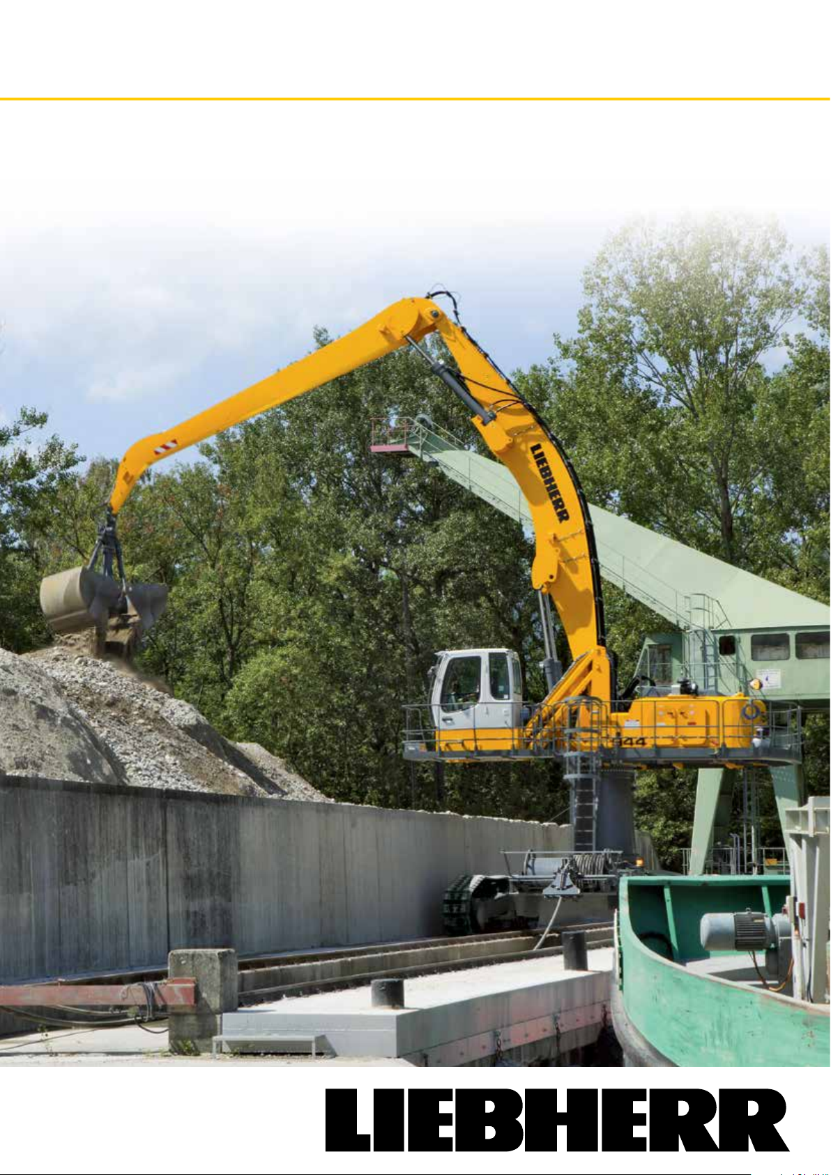
Excavators Electric
Material Handlers
ER 934 C - ER 954 C
High RiseHigh Rise
ER 934 C Operating Weight: 56,200 - 56,600 kg
ER 944 C Operating Weight: 73,400 - 74,700 kg
ER 954 C Operating Weight: 95,800 - 97,000 kg
Page 2
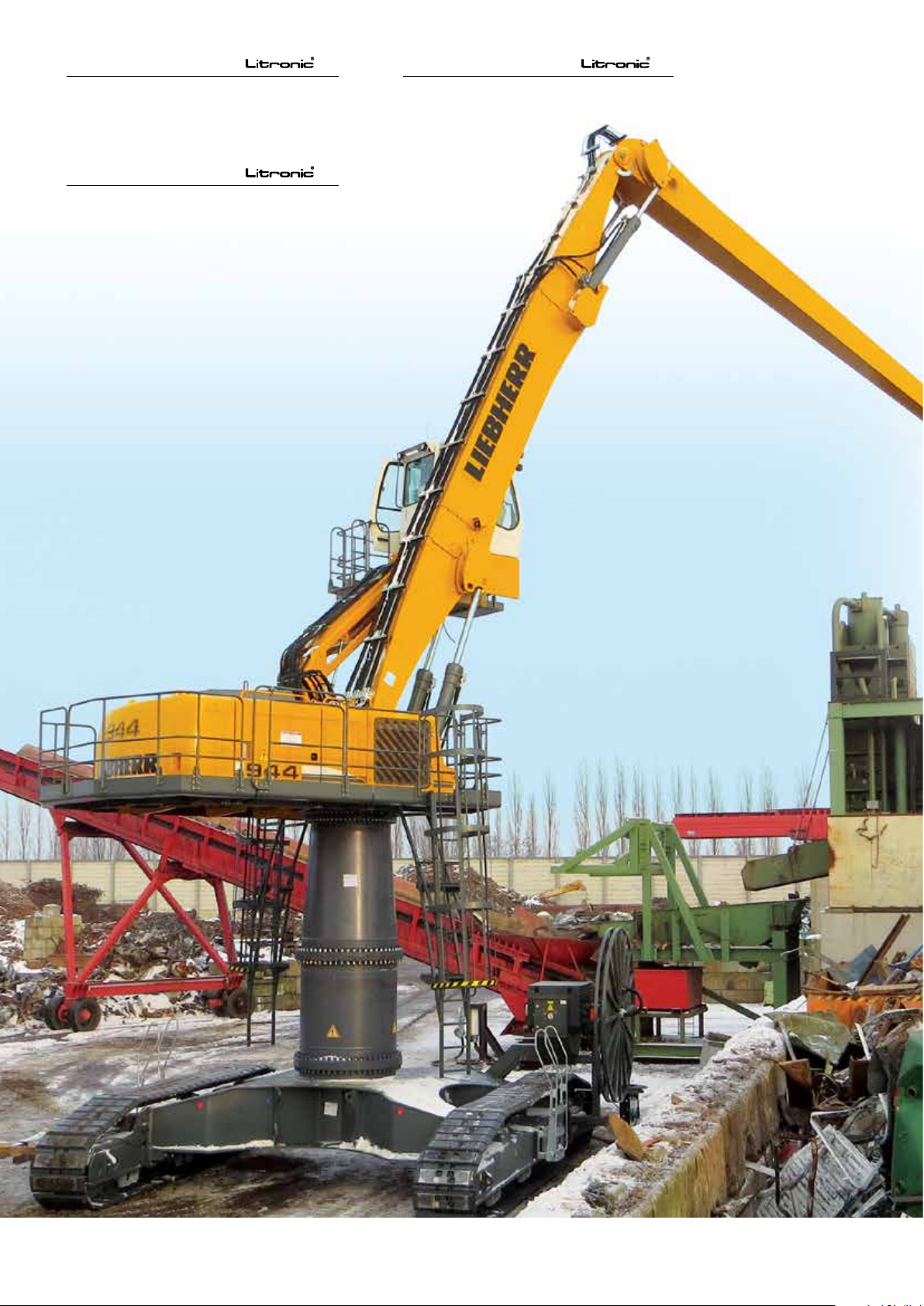
ER 934 C
ER 944 C
Operating Weight: 56,200 - 56,600 kg
Engine Capacity: 160 kW / 218 PS
ER 954 C
Operating Weight: 95,800 - 97,000 kg
Engine Capacity: 250 kW / 340 PS
Operating Weight: 73,400 - 74,700 kg
Engine Capacity: 200 kW / 272 PS
ER 934 C - ER 944 C - ER 954 C High Rise
2
Page 3
Performance
These new electric Material Handlers have been designed
to meet the specific needs of industrial handling. A range
of equipment even wider for the High Rise and uppercarriages optimized for long working radius provide the ideal
answer to all the demands which arise in the industry.
The performance of the kinematic chain formed from components from our in-house production, combined with the
power of the electric motor, maximize the performance
of the machine when it comes to lifting power, precision,
and speed of operation. The equipment’s performance is
enhanced by the mobility provided by the crawler undercarriage as well as the height of work adapted to the industrial process.
Reliability
Backed by more than 30 years experience in the construction of electric excavators, Liebherr designed the
new ER 934 C, ER 944 C and ER 954 C High Rise with the
aim of providing top performance whatever the challenge
might be. The structure of the machine, using compo-
nents from our own manufacture for the electric drive,
has been completely rethought, and so moves away
from simply being an adaptation of a diesel-engine
machine. Being intended for key functions in the
organization of industrial sites, Liebherr electric
Material Handlers provide a very high level of
reliability. The service life of the hydraulic com-
ponents has also been increased, thanks to the
constant regime of the electric drive. The concept of the
single actuator (one single electric motor for all the hydraulic functions) allows all the low-voltage functions to
be concentrated in a single box.
Comfort
Helping the operator to concentrate on his work and get
the best out of his machine is achieved by providing a comfortable driving position, good panoramic visibility, and a
highly ergonomic layout of the controls. The new electric
Material Handlers offer the same level of comfort as on the
thermal excavators (arrangement of the controls, driver’s
seat, climate control, large window areas, etc.). The electric motor system adds a further layer of comfort thanks
to the low noise emissions and absence of vibration. For
Liebherr, comfort also means ease of daily maintenance of
the machine in terms of access to the service and inspection points, so as to minimize down time.
Economy
Investing in the acquisition of an electric Material Handler is a great long-term advantage. Constant increases
in the costs of conventional energy sources are pushing
up operating charges, and reducing profi t margins considerably. Environmental criteria, in particular CO2 emissions, are also playing a constantly greater part in the
choice of power systems and working methods. With the
electric drive, Liebherr offers an economical alternative
to conventional diesel-engine machines, and a solution
with real respect for the environment. Also, the excavator
is permanently available, with no need to refill. There are
no constraints (e.g. DPF or AdBlue). Mobility is added to
economy, through custom cable reels solutions.
ER 934 C - ER 944 C - ER 954 C High Rise
3
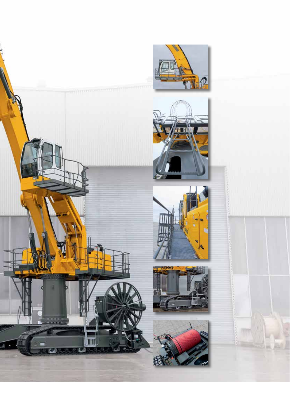
Page 4
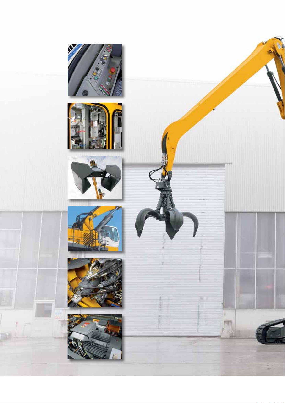
Excavator electric at a glance
Cab with special
control panel
• Control power on/off
of the excavator
• Additional interface for
the cable reel option
Integrated electric cabinet
• Hard conditions
• Pressure relief system
to prevent the intrusion
of dust
• Closing with padlocks
• Robust
Wide range of tools,
including
• Grapples
• Shells for Loose Material
• Wood clamps
• Quick change adapter
Wide range of equipments
• Range of equipments from
the stationary excavators
for a moving machine
• Special adjustments on
demand
Kinematic chain Liebherr
• High work precision
• Immediate response
• Large power for
maximum productivity
Electric motor
• Hard conditions
• Constant regime
whatever the load
• Integrated sensors for
maximum availability
ER 934 C - ER 944 C - ER 954 C High Rise
4
Page 5
Cab elevation
• Wide range of rigid cab elevation
and adjustable hydraulically
• High visibility of the working
area and the site
Access
• As standard, safety and comfort
to access the work space
• Handrails, non-slip surfaces
Walkways
• Wide walkways and handrails
all around the excavator
• Can be tted with secure
trapdoors, wicket doors
Undercarriage
• Derived from thermal excavators,
specifically equipped for electric
excavators :
- cable entry
- power connector
- slip ring collector
• Stability for all operations
Cable entry
• In free-standing, cable left
entry as standard, right or rear
on demand
• Rear cable reel for a large radius
of action and movement facilities
• Side cable reel for in-line
processes
ER 934 C - ER 944 C - ER 954 C High Rise
5
Page 6
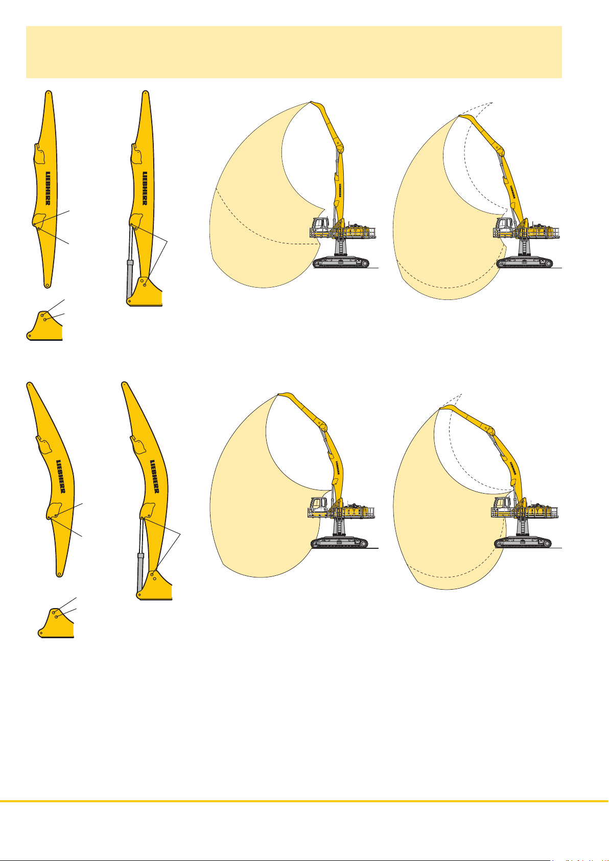
VarioLiftPlus
Variable Boom Mounting Positions for Optimized Lift Capacities
Hole A
Hole B
Hole 3
Hole 2
Version 2A
R0082
2A
with the same working range with a different working range
2A
3B
3B
R0082
3A
Kinematic variant 2A:
Increased lift capacities above ground level
Kinematic variant 3B:
Kinematic variant 3A:
Altered range curve with additional reach
depth, e.g. for unloading from ships
Increased lift capacities below ground level
and when working at large outreach
R0110
with a different working range
R0082
Hole C
Hole D
Hole 3
Hole 2
Version 3D
3D
3D
Kinematic variant 3D:
Increased lift capacities below ground level
and when working at large outreach
R0110
R0110
3C
Kinematic variant 3C:
Altered range curve with additional reach
depth, e.g. for unloading from ships
6 ER 934 C ER 944 C ER 954 C High Rise
Page 7
Technical Data
Electric Motor
������������������������������
Engine
934 944 954
Power rating
(as per CEI 34-1)
Rated voltage
Number of poles
Design type
Standard degree of protection
Insulation
Cooling
Heat protection for windings
Heat protection for bearings
Anti-condensation heating system resistors
������������������
���������������������
������������������
�����������������������
��������������������������
�����������������������������
induction motor dedicated definition Liebherr
160
kW (218 HP)
400 V – 50 Hz *
4
horizontal axle B35
axle height 315 mm
��
IP55
class F
IC06
200
kW (272 HP)
250
kW (340 HP)
Electric System
The 400 V electrical cabinet provides a degree of protection to IP55.
This houses the following components:
– Electrical cabinet – remote control inside the cab
– Star/delta starter for motor
– Outlets for supplying auxiliary elements: heating, climate control
– Overheat protection devices
– Integrated heating and ventilation
– Filtered booster
– Transformers – rectifier for 24 V control circuit
– Motor protection
– Auxiliary batteries: 2 x 135 Ah/12 V: secured functions: lighting for excavator/
attachment position (option)
– Connecting inside closed panel
– Equipment: slip ring collector
power connector
embedded cable reel
Swing Drive
����������������������������
Drive by
Transmission
Swing ring
934 944 954
Swing speed
Swing torque
Holding brake
Option
����������������������
�������������������������
����������������������
����������������������
���������������������
������������������������������
hydraulic swash plate motor with integrated
brake valves
Liebherr compact planetary reduction gear
Liebherr, sealed single race ball bearing swing
ring, internal teeth
0 – 9.4 RPM 0 – 7.9 RPM 0 – 5.6 RPM
stepless stepless stepless
81.07 kNm 119 kNm 167.23 kNm
oil-bath disk brake (negative action)
pedal controlled positioning brake
Operator’s Cab
���������������������������������
Cab
Operator’s seat
Controls
Monitoring
Climate control
Noise emission
2000/14/EC 934 944 954
L
WA
�������������������
����������������������������
�������������������������
�������������������
(surround noise)
single shell concept with shaped profiles, resil-
iently mounted, sound insulated, tinted windows.
Front window can be folded away under roof,
door with sliding window
shock absorbing suspension, adjustable to
operator’s weight, 6-way adjustable seat
integrated into adjustable seat consoles
menu driven digital display of current operating
conditions. Automatic monitoring, display, warn-
ing (audible and visual signal) and saving of
machine malfunction data, such as overheating
ofwindings, motor bearings, or low hydraulic
oillevel
standard climate control system, combined
cooler/heater, additional dust filter in the outside/
fresh air circuit
�������
101 dB(A) 103 dB(A) 105 dB(A)
ER 954 C ER 944 C ER 934 C
Hydraulic System
934 944 954
Hydraulic pump
for the attachment
Max. flow
Max. pressure
Pumpenansteuerung
Hydraulic pump
for the swing drive
Max. flow
Max. pressure
Hydraulic tank
Hydraulic system
���������������������������
Filtration
�����������������������������
Cooling
Tool Control
�����������������������
����������
���������������������
���������������
������������
����������
���������������������
���������������
��������������������
�����������������
two Liebherr swash plate pumps with variable
output
2 x 253 l/min. 2 x 305 l/min. 2 x 341 l/min.
350 bar
electro-hydraulic, with electronic regulation by
power limit, minimum pump flow at max. pres-
sure, distribution of oil to different receptor
components proportional to demand
reversible swash plate pump, in closed circuit
170 l/min. 205 l/min. 205 l/min.
370 bar
340 l 460 l 440 l
550 l 710 l 790 l
934: filter in the return circuit, with integrated fine
filter elements (5 μm)
944/954: 2 filters in the return circuit, with inte-
grated fine filter elements (5 μm)
radiator equipped with hydrostatic drive fan for
cooling the hydraulic oil and climate control
condenser
10 flow rates and pressures adjustable as option
for optional accessories
Hydraulic Controls
Power distribution
Flow summation
Closed-loop circuit
Control
Attachment and swing
Travel
Additional functions
����������������
������������
���������
�����
�������������������������
��������������
with the aid of hydraulic distributors with
integrated safety valves
to boom stick and stick
for uppercarriage swing drive mechanism
proportional by handling element in cross
operation
proportional by pedals or by lever
proportional by pedals or by toggle switch
Undercarriage
Version HR
��������������������������������
Drive
Transmission
934 944 954
Travel speed
Drawbar pull max.
Track components
Track rollers/Carrier rollers
Tracks
Track pads
Digging locks
Brake valves
����������������������
����������������������
����������������
���������������
������������������������������
������������������������
���������������������
����������������������
Liebherr swash plate motors with integrated
brake valves on both sides
Liebherr planetary reduction gears
2.6 km/h 2.6 km/h 2.5 km/h
318 kN 363 kN 397 kN
maintenance- maintenance- maintenance-
free free free
B 60 D 7 G D 8 K
�����
9/2 13/3 13/3
sealed and greased
triple grouser
wet multi-discs (spring applied, pressure
released)
integrated into travel motor
Attachment
��������������������������������
Type
Hydraulic cylinders
�������������������������������
Pivots
Lubrication
VarioLift
������������������������
�������������������������
Plus
���������������
high-strength steel for extreme stresses. Bearings
designed for optimum distribution of stresses
Liebherr cylinders with end-of-travel shock
absorbing, fitted with guide and sealing joints
sealed, low maintenance
centralised semi-automatic Liebherr lubrication
system
variable boom mounting positions for optimized
lift capacities
* Other voltages and frequencies possible on request.
ER 934 C ER 944 C ER 954 C High Rise 7
Page 8
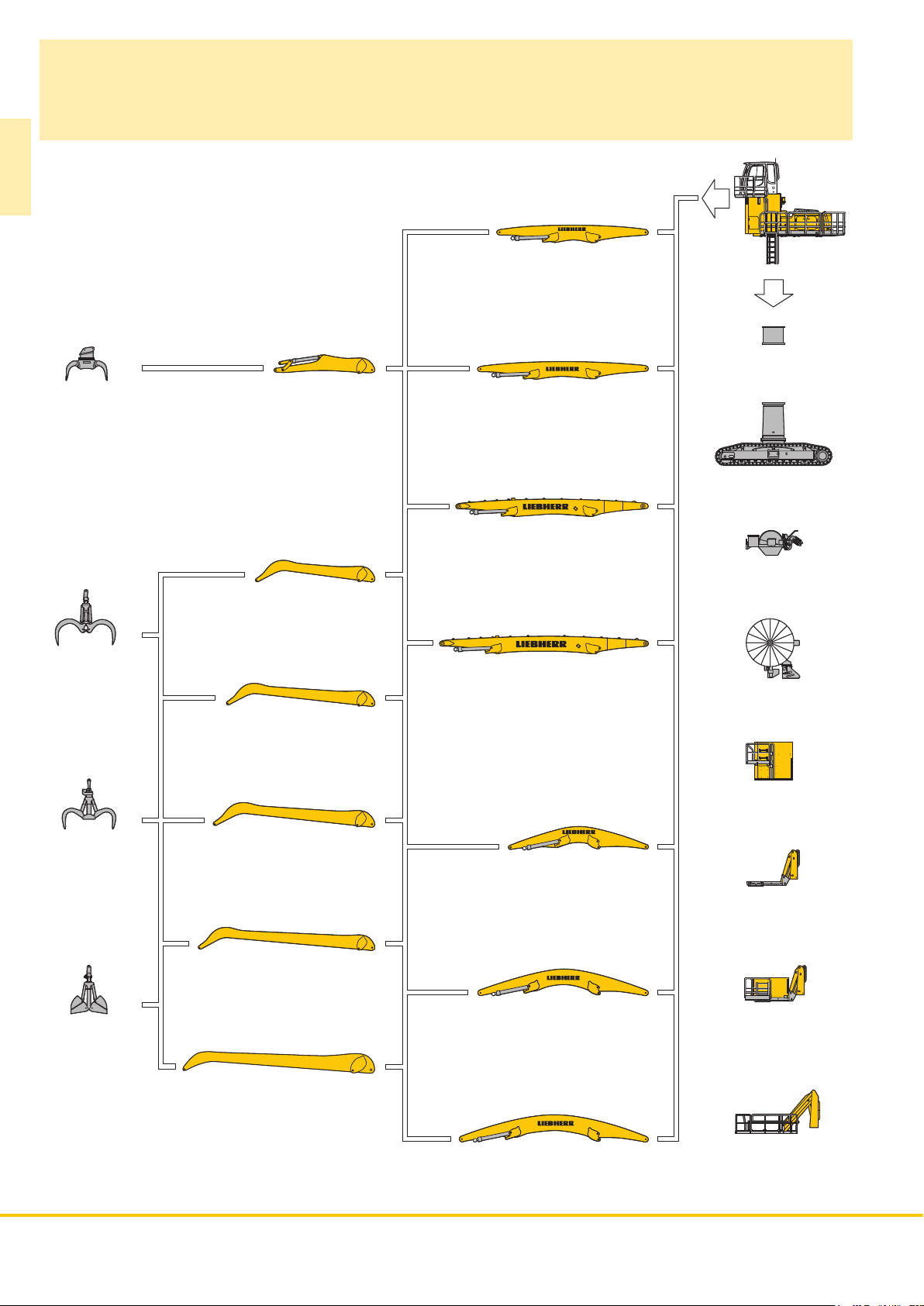
The Right Attachment
for Every Application
ER 934 C
Industrial-type straight mono boom 7.60 m
Sorting grapple
Stick 5.00 m
Industrial-type straight mono boom 8.60 m
Uppercarriage Elevation
Undercarriage
Wood grapple
Multi-tine grapple
Industrial-type straight mono boom 9.60 m*
Cylindrical cable reel
Industrial stick 6.00 m
Industrial-type straight mono boom 10.60 m*
Spiral cable reel
Industrial stick 7.50 m
Rigid cab elevation
Industrial stick 8.00 m
Industrial-type angled mono boom 7.60 m
Hydraulic Cab Elevation
Industrial stick 9.00 m*
Clamshell bucket
* presented configurations
8 ER 934 C ER 944 C ER 954 C High Rise
Industrial stick 9.00 m*
Industrial-type angled mono boom 8.60 m
Industrial-type angled mono boom 9.60 m*
Hydraulic Cab Elevation
+ Rigid cab elevation
Hydraulic Cab Elevation
+ Intermediate Piece
Page 9
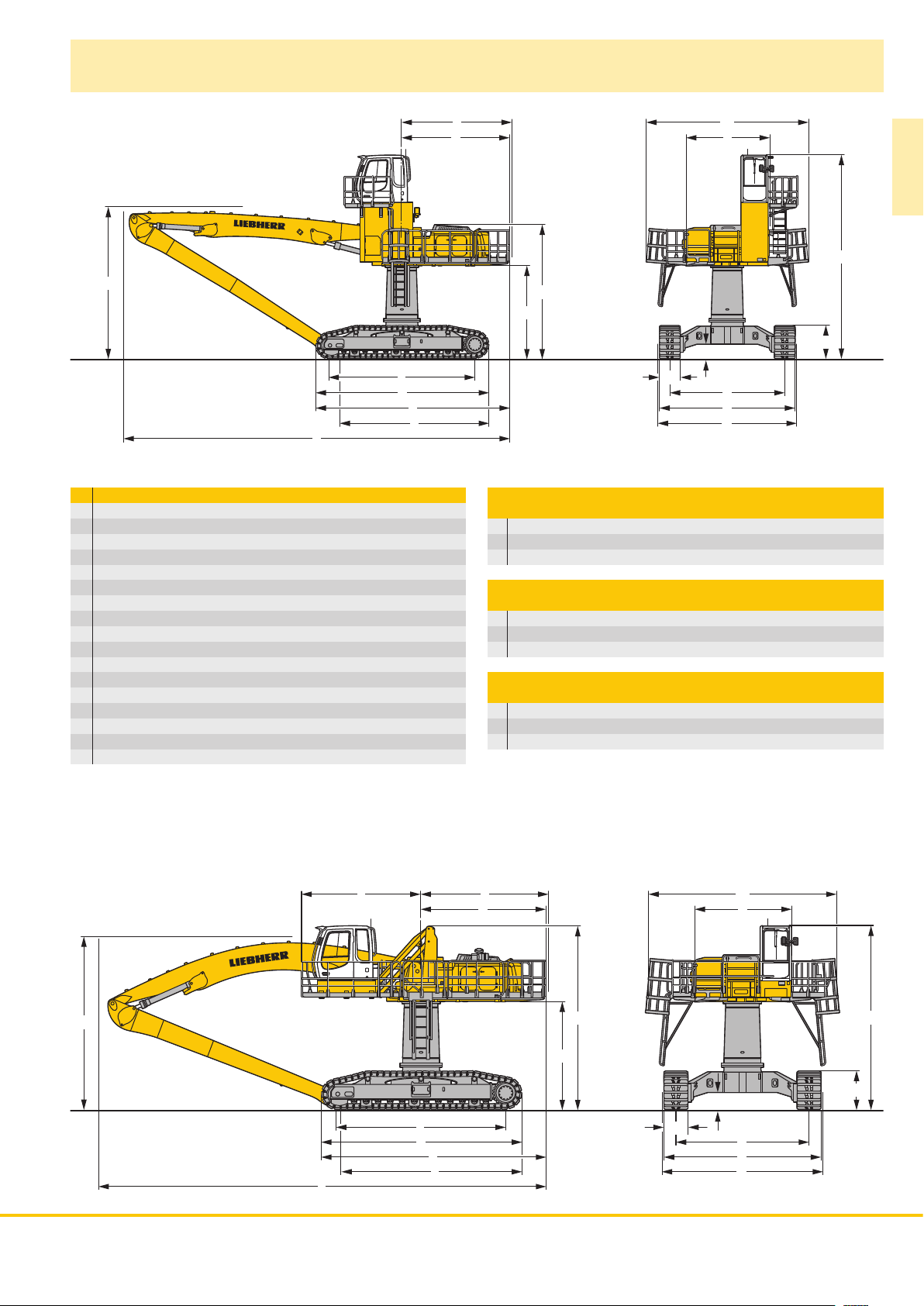
Dimensions
WW
LL
UU
ZZ
VV
XX
mm
A 3,225
A1 5,935
C 5,800
D 3,930
E 4,030
F 3,770
H 5,780
K 3,395
L 5,350
P 1,215
Q 530
S 4,200
U 6,320
N 750
B 4,950
G 5,060
Z 7,095
E = Tail radius
EE
DD
HH
KK
NN
A1A1
AA
QQ
SS
BB
GG
Industrial-Type Straight Mono Boom 9.60 m
and Industrial Stick m 9.00 10.00
V mm 5,800 5,450
W mm 4,850 5,550
X mm 14,100 14,100
Industrial-Type Straight Mono Boom 10.60 m
and Industrial Stick m 9.00 10.00
V mm 6,950 6,000
W mm 4,900 4,900
X mm 15,100 15,100
Industrial-Type Angled Mono Boom 9.60 m
and Industrial Stick m 9.00 10.00
V mm 5,700 5,500
W mm 5,450 6,500
X mm 14,100 14,100
ER 934 C
CC
PP
R0083
EEFF
DD
WW
LL
UU
ZZ
VV
XX
HH
KK
NN
A1A1
AA
CC
QQ
SS
BB
GG
PP
R0084
ER 934 C ER 944 C ER 954 C High Rise 9
Page 10
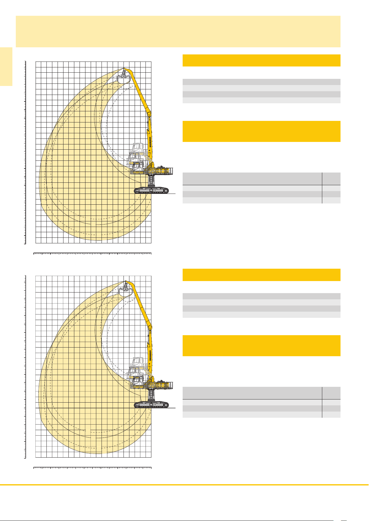
Industrial Attachment
with Industrial-Type Straight Mono Boom 9.60 m
m
ft
24
75
22
70
ER 934 C
20
65
60
18
55
16
50
14
45
40
12
35
10
30
8
25
20
6
15
4
10
2
5
0
0
-5
-2
-10
-15
-20
-25
-30
-4
-6
-8
16
18
20
1
3
2
4
6
8
10
12
14
R0100
Attachment Envelope
Kinematic variants 2A
1 with industrial stick 9.00 m
2 with industrial stick 9.00 m and grapple model GM 70C
3 with industrial stick 10.00 m
4 with industrial stick 10.00 m and grapple model GM 70C
Operating Weight
and Ground Pressure
Operating weight includes basic machine with hydraulic cab elevation
+ intermediate piece 0.5 m, counterweight 7.5 t, industrial-type
straight mono boom 9.60 m, industrial stick 9.00 m and grapple model
GM 70C with 5 semi-closed tines 0.80 m
Undercarriage HR
Pad width mm 750
Weight kg 56,200
Ground pressure kg/cm
0
2
4
3
(1,705 kg).
2
0.70
75
70
65
60
55
50
45
40
35
30
25
20
15
10
-10
-15
-20
-25
-30
ft
5
0
-5
70 65 60
m
24
22
20
18
16
14
12
10
8
6
4
2
0
-2
-4
-6
-8
20
18
55 50
16
0mft
5
15 10
25 20
30
35
40
54
R0101
Attachment Envelope
Kinematic variants 3B
1 with industrial stick 9.00 m
2 with industrial stick 9.00 m and grapple model GM 70C
3 with industrial stick 10.00 m
4 with industrial stick 10.00 m and grapple model GM 70C
Operating Weight
and Ground Pressure
Operating weight includes basic machine with hydraulic cab elevation
+ intermediate piece 0.5 m, counterweight 7.5 t, industrial-type
straight mono boom 9.60 m, industrial stick 10.00 m and grapple
model GM 70C with 5 semi-closed tines 0.80 m
Undercarriage HR
Pad width mm 750
Weight kg 56,400
Ground pressure kg/cm
1
3
2
4
0
2
4
6
8
10
12
14
3
(1,705 kg).
2
0.70
70 65 60
55 50
35
40
54
10 ER 934 C ER 944 C ER 954 C High Rise
30
25 20
15 10
0mft
5
Page 11
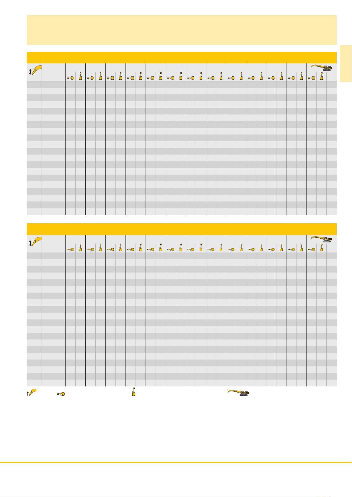
Lift Capacities
with Industrial-Type Straight Mono Boom 9.60 m
Industrial Stick 9.00 m (Variant 2A)
3.0 m 4.5 m 6.0 m 7.5 m 9.0 m 10.5 m 12.0 m 13.5 m 15.0 m 16.5 m 18.0 m 19.5 m
Under m carriage m
24.0
HR
22.5
HR
21.0
19.5
18.0
16.5
15.0
13.5
12.0
10.5
9.0
7.5
6.0
4.5
3.0
1.5
0
– 1.5
– 3.0
– 4.5
HR
HR
HR
HR
HR
HR
HR
HR
HR
HR
HR
HR
HR
HR
HR
HR
HR
HR
6.6* 6.6* 5.3* 5.3* 7.2
6.4* 6.4* 5.4* 5.4* 4.3* 4.3* 10.0
6.2* 6.2* 5.3* 5.3* 3.8* 3.8* 3.7* 3.7* 12.0
6.5* 6.5* 5.9* 5.9* 5.1* 5.1* 3.5* 3.5* 3.4* 3.4* 13.5
6.1* 6.1* 5.5* 5.5* 4.8* 4.8* 3.2* 3.2* 14.8
6.1* 6.1* 5.5* 5.5* 5.0* 5.0* 4.2* 4.2* 3.1* 3.1* 15.7
6.1* 6.1* 5.5* 5.5* 5.0* 5.0* 4.5* 4.5* 3.0* 3.0* 3.0* 3.0* 16.5
6.9* 6.9* 6.2* 6.2* 5.6* 5.6* 5.0* 5.0* 4.5* 4.5* 4.0* 4.0* 2.9* 2.9* 17.1
7.1* 7.1* 6.3* 6.3* 5.6* 5.6* 5.0* 5.0* 4.5* 4.5* 4.0* 4.0* 2.9* 2.9* 17.6
7.8* 7.8* 7.4* 7.4* 6.5* 6.5* 5.7* 5.7* 5.1* 5.1* 4.5* 4.5* 3.9* 3.9* 2.9* 2.9* 17.9
8.6* 8.6* 9.1* 9.1* 7.7* 7.7* 6.6* 6.6* 5.8* 5.8* 5.1* 5.1* 4.4* 4.4* 3.9* 3.9* 3.1* 3.1* 2.9* 2.9* 18.1
16.0* 16.0* 11.9* 11.9* 9.5* 9.5* 7.9* 7.9* 6.7* 6.7* 5.8* 5.8* 5.0* 5.0* 4.4* 4.4* 3.7* 3.7* 3.0* 3.0* 2.8* 2.8* 18.2
1.6* 1.6* 9.4* 9.4* 12.3* 12.3* 9.7* 9.7* 7.9* 7.9* 6.7* 6.7* 5.7* 5.7* 4.9* 4.9* 4.2* 4.2* 3.5* 3.5* 2.7* 2.7* 2.5* 2.5* 18.2
1.7* 1.7* 4.8* 4.8* 12.1* 12.1* 9.5* 9.5* 7.8* 7.8* 6.5* 6.5* 5.6* 5.6* 4.7* 4.7* 4.0* 4.0* 3.3* 3.3* 2.3* 2.3* 18.0
2.3* 2.3* 4.4* 4.4* 9.4* 9.4* 9.1* 9.1* 7.4* 7.4* 6.2* 6.2* 5.3* 5.3* 4.4* 4.4* 3.7* 3.7* 2.8* 2.8* 2.0* 2.0* 17.6
3.0* 3.0* 4.8* 4.8* 8.4* 8.4* 8.2* 8.2* 6.8* 6.8* 5.7* 5.7* 4.8* 4.8* 4.0* 4.0* 3.2* 3.2* 2.2* 2.2* 2.2* 2.2* 16.5
8.4* 8.4* 7.0* 7.0* 5.9* 5.9* 4.9* 4.9* 4.1* 4.1* 3.3* 3.3* 2.5* 2.5* 14.9
4.7* 4.7* 3.9* 3.9* 3.5* 3.5* 11.3
ER 934 C
Industrial Stick 10.00 m (Variant 2A)
3.0 m 4.5 m 6.0 m 7.5 m 9.0 m 10.5 m 12.0 m 13.5 m 15.0 m 16.5 m 18.0 m 19.5 m
Under m carriage m
24.0
HR
22.5
HR
21.0
HR
19.5
HR
18.0
HR
16.5
HR
15.0
HR
13.5
HR
12.0
HR
10.5
HR
9.0
HR
7.5
HR
6.0
HR
4.5
HR
3.0
HR
1.5
HR
0
HR
– 1.5
HR
– 3.0
HR
– 4.5
HR
Height Can be slewed through 360° In longitudinal position of undercarriage Max. reach * Limited by hydr. capacity
The lift capacities are stated in metric tonnes (t) on the lifting gear’s stick tip, and can be lifted 360° on firm, level supporting surface. Capacities
are valid for 750 mm track flat pads. Indicated loads are based on ISO 10567 standard and do not exceed 75 % of tipping or 87 % of hydraulic
capacity (indicated via *). Lifting capacity of the excavator is limited by machine stability, hydraulic capacity and maximum permissible load of the
load hook.
According to European Standard, EN 474-5: In the European Union excavators have to be equipped with an overload warning device, a load
diagram and automatic safety check valves on hoist cylinders and stick cylinder(s), when they are used for lifting operations which require the use
of lifting accessories.
5.6* 5.6* 5.5* 5.5* 6.1
5.7* 5.7* 4.6* 4.6* 4.0* 4.0* 9.5
5.5* 5.5* 4.6* 4.6* 3.4* 3.4* 11.8
5.3* 5.3* 4.5* 4.5* 3.1* 3.1* 13.5
5.6* 5.6* 5.1* 5.1* 4.2* 4.2* 2.8* 2.8* 14.9
5.8* 5.8* 5.2* 5.2* 4.8* 4.8* 3.8* 3.8* 2.7* 2.7* 16.0
5.7* 5.7* 5.2* 5.2* 4.8* 4.8* 4.4* 4.4* 3.1* 3.1* 2.6* 2.6* 16.9
5.8* 5.8* 5.2* 5.2* 4.8* 4.8* 4.3* 4.3* 3.9* 3.9* 2.5* 2.5* 17.6
5.9* 5.9* 5.3* 5.3* 4.8* 4.8* 4.3* 4.3* 3.9* 3.9* 2.8* 2.8* 2.4* 2.4* 18.2
6.0* 6.0* 5.4* 5.4* 4.8* 4.8* 4.4* 4.4* 3.9* 3.9* 3.4* 3.4* 2.4* 2.4* 18.6
6.8* 6.8* 6.2* 6.2* 5.5* 5.5* 4.9* 4.9* 4.4* 4.4* 3.9* 3.9* 3.4* 3.4* 2.4* 2.4* 19.0
7.1* 7.1* 7.3* 7.3* 6.3* 6.3* 5.6* 5.6* 4.9* 4.9* 4.4* 4.4* 3.8* 3.8* 3.3* 3.3* 2.4* 2.4* 19.1
6.3* 6.3* 8.7* 8.7* 9.1* 9.1* 7.6* 7.6* 6.5* 6.5* 5.6* 5.6* 4.9* 4.9* 4.3* 4.3* 3.8* 3.8* 3.2* 3.2* 2.5* 2.5* 19.2
4.6* 4.6* 16.2* 16.2* 11.9* 11.9* 9.4* 9.4* 7.7* 7.7* 6.5* 6.5* 5.6* 5.6* 4.9* 4.9* 4.2* 4.2* 3.6* 3.6* 3.0* 3.0* 2.3* 2.3* 19.2
2.0* 2.0* 6.9* 6.9* 12.1* 12.1* 9.5* 9.5* 7.7* 7.7* 6.5* 6.5* 5.5* 5.5* 4.8* 4.8* 4.1* 4.1* 3.4* 3.4* 2.7* 2.7* 2.0* 2.0* 19.0
2.2* 2.2* 4.9* 4.9* 11.7* 11.7* 9.2* 9.2* 7.5* 7.5* 6.3* 6.3* 5.3* 5.3* 4.5* 4.5* 3.8* 3.8* 3.1* 3.1* 2.3* 2.3* 1.7* 1.7* 18.7
2.8* 2.8* 4.7* 4.7* 9.1* 9.1* 8.6* 8.6* 7.1* 7.1* 5.9* 5.9* 5.0* 5.0* 4.2* 4.2* 3.4* 3.4* 2.7* 2.7* 1.9* 1.9* 17.8
3.4* 3.4* 5.1* 5.1* 8.5* 8.5* 7.7* 7.7* 6.4* 6.4* 5.3* 5.3* 4.4* 4.4* 3.7* 3.7* 2.9* 2.9* 2.1* 2.1* 16.5
7.6* 7.6* 6.4* 6.4* 5.4* 5.4* 4.5* 4.5* 3.7* 3.7* 2.9* 2.9* 2.5* 2.5* 14.3
ER 934 C ER 944 C ER 954 C High Rise 11
Page 12
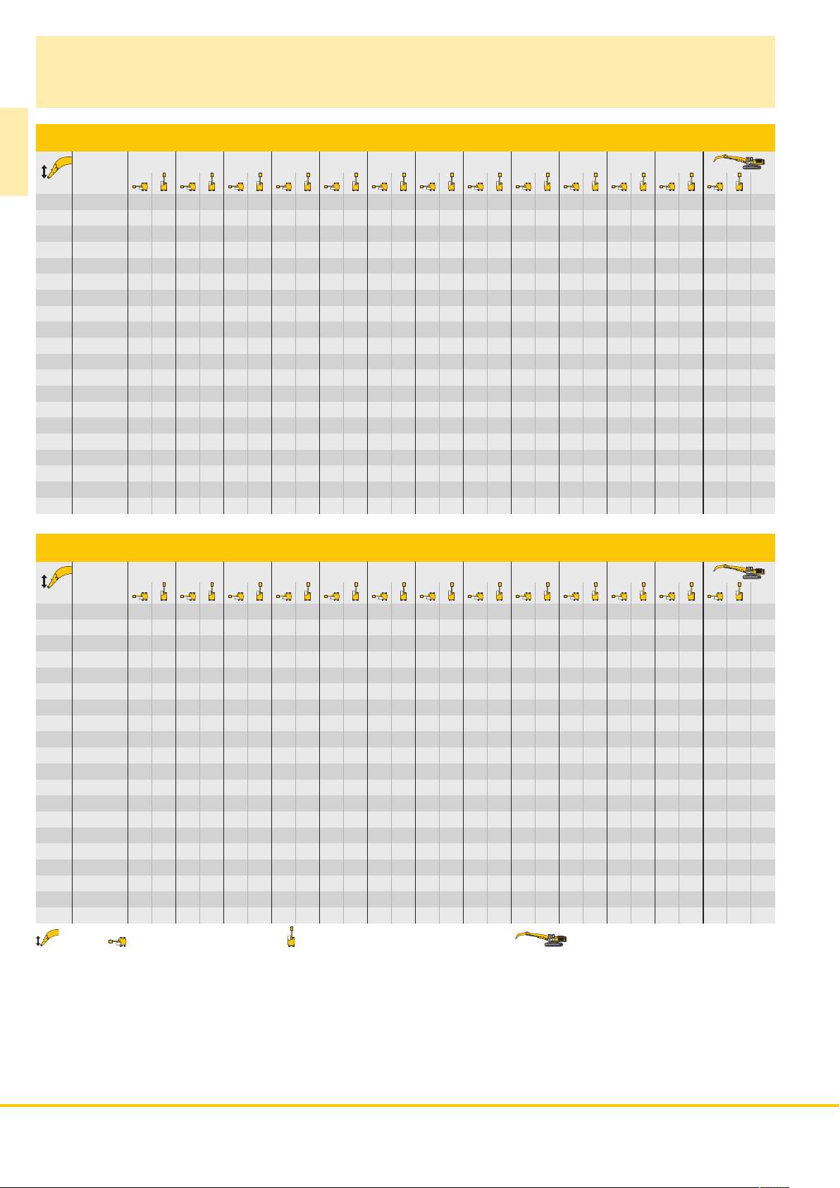
Lift Capacities
with Industrial-Type Straight Mono Boom 9.60 m
Industrial Stick 9.00 m (Variant 3B)
3.0 m 4.5 m 6.0 m 7.5 m 9.0 m 10.5 m 12.0 m 13.5 m 15.0 m 16.5 m 18.0 m 19.5 m
Under m carriage m
ER 934 C
24.0
HR
22.5
HR
21.0
19.5
18.0
16.5
15.0
13.5
12.0
10.5
9.0
7.5
6.0
4.5
3.0
1.5
0
– 1.5
– 3.0
– 4.5
HR
HR
HR
HR
HR
HR
HR
HR
HR
HR
HR
HR
HR
HR
HR
HR
HR
HR
5.4* 5.4* 5.2* 5.2* 7.7
6.4* 6.4* 5.6* 5.6* 4.2* 4.2* 10.4
5.4* 5.4* 5.1* 5.1* 4.1* 4.1* 3.7* 3.7* 12.3
5.2* 5.2* 4.9* 4.9* 4.7* 4.7* 3.9* 3.9* 3.4* 3.4* 13.8
4.8* 4.8* 4.5* 4.5* 4.4* 4.4* 3.2* 3.2* 15.0
4.7* 4.7* 4.5* 4.5* 4.3* 4.3* 4.1* 4.1* 3.1* 3.1* 15.9
5.1* 5.1* 4.8* 4.8* 4.5* 4.5* 4.3* 4.3* 4.1* 4.1* 3.4* 3.4* 3.0* 3.0* 16.7
5.3* 5.3* 5.0* 5.0* 4.6* 4.6* 4.4* 4.4* 4.1* 4.1* 3.9* 3.9* 2.9* 2.9* 17.3
5.6* 5.6* 5.2* 5.2* 4.8* 4.8* 4.5* 4.5* 4.2* 4.2* 3.9* 3.9* 2.9* 2.9* 17.8
6.8* 6.8* 6.1* 6.1* 5.5* 5.5* 5.0* 5.0* 4.6* 4.6* 4.3* 4.3* 4.0* 4.0* 3.1* 3.1* 2.9* 2.9* 18.1
6.5* 6.5* 8.9* 8.9* 7.6* 7.6* 6.5* 6.5* 5.8* 5.8* 5.2* 5.2* 4.7* 4.7* 4.3* 4.3* 4.0* 4.0* 3.5* 3.5* 2.9* 2.9* 18.3
14.0* 14.0* 10.4* 10.4* 8.4* 8.4* 7.0* 7.0* 6.1* 6.1* 5.4* 5.4* 4.9* 4.9* 4.4* 4.4* 4.0* 4.0* 3.6* 3.6* 3.0* 3.0* 18.3
1.3* 1.3* 7.3* 7.3* 11.5* 11.5* 9.1* 9.1* 7.5* 7.5* 6.4* 6.4* 5.6* 5.6* 5.0* 5.0* 4.5* 4.5* 4.1* 4.1* 3.6* 3.6* 3.1* 3.1* 18.3
1.6* 1.6* 4.3* 4.3* 12.3* 12.3* 9.6* 9.6* 7.8* 7.8* 6.6* 6.6* 5.8* 5.8* 5.1* 5.1* 4.5* 4.5* 4.0* 4.0* 3.4* 3.4* 3.2* 3.2* 18.1
2.2* 2.2* 4.2* 4.2* 8.7* 8.7* 9.8* 9.8* 8.0* 8.0* 6.8* 6.8* 5.8* 5.8* 5.1* 5.1* 4.5* 4.5* 3.9* 3.9* 3.4* 3.4* 17.6
4.6* 4.6* 8.0* 8.0* 9.8* 9.8* 8.0* 8.0* 6.8* 6.8* 5.8* 5.8* 5.0* 5.0* 4.4* 4.4* 3.7* 3.7* 3.7* 3.7* 16.5
8.2* 8.2* 9.5* 9.5* 7.8* 7.8* 6.6* 6.6* 5.6* 5.6* 4.8* 4.8* 4.2* 4.2* 14.8
Industrial Stick 10.00 m (Variant 3B)
3.0 m 4.5 m 6.0 m 7.5 m 9.0 m 10.5 m 12.0 m 13.5 m 15.0 m 16.5 m 18.0 m 19.5 m
Under m carriage m
24.0
HR
22.5
HR
21.0
HR
19.5
HR
18.0
HR
16.5
HR
15.0
HR
13.5
HR
12.0
HR
10.5
HR
9.0
HR
7.5
HR
6.0
HR
4.5
HR
3.0
HR
1.5
HR
0
HR
– 1.5
HR
– 3.0
HR
– 4.5
HR
Height Can be slewed through 360° In longitudinal position of undercarriage Max. reach * Limited by hydr. capacity
The lift capacities are stated in metric tonnes (t) on the lifting gear’s stick tip, and can be lifted 360° on firm, level supporting surface. Capacities
are valid for 750 mm track flat pads. Indicated loads are based on ISO 10567 standard and do not exceed 75 % of tipping or 87 % of hydraulic
capacity (indicated via *). Lifting capacity of the excavator is limited by machine stability, hydraulic capacity and maximum permissible load of the
load hook.
According to European Standard, EN 474-5: In the European Union excavators have to be equipped with an overload warning device, a load
diagram and automatic safety check valves on hoist cylinders and stick cylinder(s), when they are used for lifting operations which require the use
of lifting accessories.
5.9* 5.9* 5.3* 5.3* 6.7
5.8* 5.8* 4.8* 4.8* 4.0* 4.0* 9.9
5.2* 5.2* 4.8* 4.8* 3.5* 3.5* 3.4* 3.4* 12.1
4.6* 4.6* 4.4* 4.4* 3.4* 3.4* 3.0* 3.0* 13.8
4.4* 4.4* 4.2* 4.2* 4.1* 4.1* 3.0* 3.0* 2.8* 2.8* 15.1
4.3* 4.3* 4.1* 4.1* 4.0* 4.0* 3.9* 3.9* 2.7* 2.7* 16.2
4.3* 4.3* 4.1* 4.1* 3.9* 3.9* 3.8* 3.8* 3.4* 3.4* 2.6* 2.6* 17.1
4.4* 4.4* 4.2* 4.2* 4.0* 4.0* 3.8* 3.8* 3.6* 3.6* 2.5* 2.5* 17.8
4.5* 4.5* 4.3* 4.3* 4.0* 4.0* 3.8* 3.8* 3.6* 3.6* 3.1* 3.1* 2.4* 2.4* 18.4
5.1* 5.1* 4.7* 4.7* 4.4* 4.4* 4.1* 4.1* 3.9* 3.9* 3.7* 3.7* 3.5* 3.5* 2.4* 2.4* 18.8
5.5* 5.5* 5.0* 5.0* 4.6* 4.6* 4.3* 4.3* 4.0* 4.0* 3.7* 3.7* 3.5* 3.5* 2.4* 2.4* 19.1
6.8* 6.8* 6.0* 6.0* 5.4* 5.4* 4.8* 4.8* 4.4* 4.4* 4.1* 4.1* 3.8* 3.8* 3.5* 3.5* 2.4* 2.4* 19.3
6.9* 6.9* 9.3* 9.3* 7.6* 7.6* 6.5* 6.5* 5.7* 5.7* 5.1* 5.1* 4.6* 4.6* 4.2* 4.2* 3.9* 3.9* 3.5* 3.5* 2.5* 2.5* 19.3
3.0* 3.0* 14.6* 14.6* 10.6* 10.6* 8.4* 8.4* 7.0* 7.0* 6.0* 6.0* 5.3* 5.3* 4.8* 4.8* 4.3* 4.3* 3.9* 3.9* 3.5* 3.5* 2.5* 2.5* 19.3
1.8* 1.8* 5.9* 5.9* 11.6* 11.6* 9.1* 9.1* 7.5* 7.5* 6.3* 6.3* 5.5* 5.5* 4.9* 4.9* 4.4* 4.4* 3.9* 3.9* 3.5* 3.5* 2.6* 2.6* 19.1
2.1* 2.1* 4.5* 4.5* 10.7* 10.7* 9.5* 9.5* 7.7* 7.7* 6.5* 6.5* 5.6* 5.6* 4.9* 4.9* 4.4* 4.4* 3.9* 3.9* 3.4* 3.4* 2.9* 2.9* 18.7
2.7* 2.7* 4.6* 4.6* 8.5* 8.5* 9.6* 9.6* 7.9* 7.9* 6.6* 6.6* 5.7* 5.7* 4.9* 4.9* 4.3* 4.3* 3.8* 3.8* 3.2* 3.2* 17.8
5.0* 5.0* 8.1* 8.1* 9.5* 9.5* 7.8* 7.8* 6.5* 6.5* 5.6* 5.6* 4.8* 4.8* 4.2* 4.2* 3.6* 3.6* 16.4
8.3* 8.3* 9.1* 9.1* 7.5* 7.5* 6.3* 6.3* 5.3* 5.3* 4.5* 4.5* 4.2* 4.2* 14.1
12 ER 934 C ER 944 C ER 954 C High Rise
Page 13

Industrial Attachment
with Industrial-Type Straight Mono Boom 10.60 m
m
-10
-15
-20
-25
-30
ft
80
24
75
22
70
20
65
60
18
55
16
50
14
45
40
12
35
10
30
8
25
20
6
15
4
10
2
5
0
0
-5
-2
-4
-6
-8
16
18
2022
1
3
2
4
6
8
10
12
14
R0102
Attachment Envelope
Kinematic variants 2A
1 with industrial stick 9.00 m
2 with industrial stick 9.00 m and grapple model GM 65
3 with industrial stick 10.00 m
4 with industrial stick 10.00 m and grapple model GM 65
Operating Weight
and Ground Pressure
Operating weight includes basic machine with hydraulic cab elevation
+ intermediate piece 0.5 m, counterweight 7.5 t, industrial-type
straight mono boom 10.60 m, industrial stick 9.00 m and grapple
model GM 65 with 5 semi-closed tines 0.60 m
Undercarriage HR
Pad width mm 750
Weight kg 56,200
Ground pressure kg/cm
2
4
0
3
(1,415 kg).
2
0.70
ER 934 C
-10
-15
-20
-25
-30
70 65 60
m
ft
80
24
75
22
70
20
65
60
18
55
16
50
14
45
40
12
35
10
30
8
25
20
6
15
4
10
2
5
0
0
-5
-2
-4
-6
-8
55 50
R0103
Attachment Envelope
Kinematic variants 3B
1 with industrial stick 9.00 m
2 with industrial stick 9.00 m and grapple model GM 65
3 with industrial stick 10.00 m
4 with industrial stick 10.00 m and grapple model GM 65
Operating Weight
and Ground Pressure
Operating weight includes basic machine with hydraulic cab elevation
+ intermediate piece 0.5 m, counterweight 7.5 t, industrial-type
straight mono boom 10.60 m, industrial stick 10.00 m and grapple
model GM 65 with 5 semi-closed tines 0.60 m
Undercarriage HR
Pad width mm 750
Weight kg 56,400
Ground pressure kg/cm
1
3
2
4
2
4
6
8
10
12
14
16
18
2022
0
3
(1,415 kg).
2
0.70
0mft
5
15 10
25 20
30
35
40
54
70 65 60
55 50
0mft
5
15 10
25 20
30
35
40
54
ER 934 C ER 944 C ER 954 C High Rise 13
Page 14

Lift Capacities
with Industrial-Type Straight Mono Boom 10.60 m
Industrial Stick 9.00 m (Variant 2A)
3.0 m 4.5 m 6.0 m 7.5 m 9.0 m 10.5 m 12.0 m 13.5 m 15.0 m 16.5 m 18.0 m 19.5 m
Under m carriage m
ER 934 C
24.0
HR
22.5
21.0
19.5
18.0
16.5
15.0
13.5
12.0
10.5
9.0
7.5
6.0
4.5
3.0
1.5
0
– 1.5
– 3.0
– 4.5
HR
HR
HR
HR
HR
HR
HR
HR
HR
HR
HR
HR
HR
HR
HR
HR
HR
HR
HR
6.1* 6.1* 6.1* 6.1* 6.0
6.2* 6.2* 5.1* 5.1* 4.6* 4.6* 9.4
6.0* 6.0* 5.1* 5.1* 3.9* 3.9* 11.7
6.4* 6.4* 5.9* 5.9* 5.0* 5.0* 3.5* 3.5* 13.5
6.0* 6.0* 5.4* 5.4* 4.8* 4.8* 3.3* 3.3* 14.8
6.0* 6.0* 5.4* 5.4* 4.8* 4.8* 4.3* 4.3* 3.1* 3.1* 16.0
6.0* 6.0* 5.4* 5.4* 4.8* 4.8* 4.3* 4.3* 3.6* 3.6* 3.0* 3.0* 16.9
6.9* 6.9* 6.0* 6.0* 5.4* 5.4* 4.8* 4.8* 4.3* 4.3* 3.8* 3.8* 2.9* 2.9* 17.6
7.0* 7.0* 6.1* 6.1* 5.4* 5.4* 4.8* 4.8* 4.3* 4.3* 3.8* 3.8* 3.3* 3.3* 2.9* 2.9* 18.2
7.4* 7.4* 7.2* 7.2* 6.2* 6.2* 5.5* 5.5* 4.8* 4.8* 4.3* 4.3* 3.8* 3.8* 3.3* 3.3* 2.9* 2.9* 18.6
7.5* 7.5* 8.8* 8.8* 7.4* 7.4* 6.3* 6.3* 5.5* 5.5* 4.8* 4.8* 4.3* 4.3* 3.7* 3.7* 3.2* 3.2* 2.8* 2.8* 18.9
10.8* 10.8* 11.4* 11.4* 9.1* 9.1* 7.5* 7.5* 6.4* 6.4* 5.5* 5.5* 4.8* 4.8* 4.2* 4.2* 3.7* 3.7* 3.1* 3.1* 2.6* 2.6* 19.1
11.1* 11.1* 11.8* 11.8* 9.3* 9.3* 7.6* 7.6* 6.4* 6.4* 5.5* 5.5* 4.8* 4.8* 4.1* 4.1* 3.6* 3.6* 3.0* 3.0* 2.3* 2.3* 19.2
3.1* 3.1* 11.7* 11.7* 9.2* 9.2* 7.5* 7.5* 6.3* 6.3* 5.4* 5.4* 4.6* 4.6* 4.0* 4.0* 3.4* 3.4* 2.8* 2.8* 2.1* 2.1* 19.1
0.8* 0.8* 2.6* 2.6* 6.7* 6.7* 8.9* 8.9* 7.3* 7.3* 6.1* 6.1* 5.2* 5.2* 4.4* 4.4* 3.8* 3.8* 3.2* 3.2* 2.5* 2.5* 1.8* 1.8* 19.0
1.5* 1.5* 2.9* 2.9* 5.7* 5.7* 8.2* 8.2* 6.8* 6.8* 5.7* 5.7* 4.9* 4.9* 4.1* 4.1* 3.5* 3.5* 2.8* 2.8* 2.1* 2.1* 1.6* 1.6* 18.6
3.5* 3.5* 5.7* 5.7* 7.3* 7.3* 6.1* 6.1* 5.2* 5.2* 4.4* 4.4* 3.7* 3.7* 3.0* 3.0* 2.3* 2.3* 1.8* 1.8* 17.5
6.2* 6.2* 6.0* 6.0* 5.2* 5.2* 4.4* 4.4* 3.7* 3.7* 3.1* 3.1* 2.4* 2.4* 2.0* 2.0* 15.9
3.5* 3.5* 2.9* 2.9* 2.8* 2.8* 12.3
Industrial Stick 10.00 m (Variant 2A)
3.0 m 4.5 m 6.0 m 7.5 m 9.0 m 10.5 m 12.0 m 13.5 m 15.0 m 16.5 m 18.0 m 19.5 m
Under m carriage m
24.0
HR
22.5
HR
21.0
HR
19.5
HR
18.0
HR
16.5
HR
15.0
HR
13.5
HR
12.0
HR
10.5
HR
9.0
HR
7.5
HR
6.0
HR
4.5
HR
3.0
HR
1.5
HR
0
HR
– 1.5
HR
– 3.0
HR
– 4.5
HR
Height Can be slewed through 360° In longitudinal position of undercarriage Max. reach * Limited by hydr. capacity
The lift capacities are stated in metric tonnes (t) on the lifting gear’s stick tip, and can be lifted 360° on firm, level supporting surface. Capacities
are valid for 750 mm track flat pads. Indicated loads are based on ISO 10567 standard and do not exceed 75 % of tipping or 87 % of hydraulic
capacity (indicated via *). Lifting capacity of the excavator is limited by machine stability, hydraulic capacity and maximum permissible load of the
load hook.
According to European Standard, EN 474-5: In the European Union excavators have to be equipped with an overload warning device, a load
diagram and automatic safety check valves on hoist cylinders and stick cylinder(s), when they are used for lifting operations which require the use
of lifting accessories.
5.4* 5.4* 4.4* 4.4* 8.7
5.3* 5.3* 4.4* 4.4* 3.6* 3.6* 11.3
5.2* 5.2* 4.4* 4.4* 3.2* 3.2* 13.3
5.5* 5.5* 5.0* 5.0* 4.2* 4.2* 2.9* 2.9* 14.8
5.7* 5.7* 5.2* 5.2* 4.7* 4.7* 3.9* 3.9* 2.7* 2.7* 16.1
5.7* 5.7* 5.1* 5.1* 4.6* 4.6* 4.2* 4.2* 3.4* 3.4* 2.6* 2.6* 17.1
5.7* 5.7* 5.1* 5.1* 4.6* 4.6* 4.2* 4.2* 3.7* 3.7* 2.5* 2.5* 18.0
5.8* 5.8* 5.2* 5.2* 4.6* 4.6* 4.2* 4.2* 3.7* 3.7* 3.3* 3.3* 2.5* 2.5* 18.7
5.9* 5.9* 5.2* 5.2* 4.7* 4.7* 4.2* 4.2* 3.7* 3.7* 3.3* 3.3* 2.4* 2.4* 19.2
6.5* 6.5* 6.0* 6.0* 5.3* 5.3* 4.7* 4.7* 4.2* 4.2* 3.7* 3.7* 3.3* 3.3* 2.7* 2.7* 2.4* 2.4* 19.6
6.5* 6.5* 7.1* 7.1* 6.1* 6.1* 5.3* 5.3* 4.7* 4.7* 4.2* 4.2* 3.7* 3.7* 3.2* 3.2* 2.7* 2.7* 2.4* 2.4* 19.9
7.0* 7.0* 8.4* 8.4* 7.3* 7.3* 6.2* 6.2* 5.4* 5.4* 4.7* 4.7* 4.1* 4.1* 3.6* 3.6* 3.1* 3.1* 2.6* 2.6* 2.3* 2.3* 20.1
15.4* 15.4* 11.4* 11.4* 9.0* 9.0* 7.4* 7.4* 6.3* 6.3* 5.4* 5.4* 4.7* 4.7* 4.1* 4.1* 3.6* 3.6* 3.0* 3.0* 2.5* 2.5* 2.1* 2.1* 20.2
0.8* 0.8* 6.0* 6.0* 11.6* 11.6* 9.1* 9.1* 7.4* 7.4* 6.2* 6.2* 5.3* 5.3* 4.6* 4.6* 4.0* 4.0* 3.4* 3.4* 2.9* 2.9* 2.3* 2.3* 1.9* 1.9* 20.1
0.9* 0.9* 3.2* 3.2* 9.4* 9.4* 8.9* 8.9* 7.3* 7.3* 6.1* 6.1* 5.2* 5.2* 4.5* 4.5* 3.8* 3.8* 3.2* 3.2* 2.7* 2.7* 2.0* 2.0* 1.6* 1.6* 20.0
1.5* 1.5* 3.0* 3.0* 6.5* 6.5* 8.5* 8.5* 7.0* 7.0* 5.8* 5.8* 4.9* 4.9* 4.2* 4.2* 3.6* 3.6* 3.0* 3.0* 2.4* 2.4* 1.5* 1.5* 1.4* 1.4* 19.7
2.1* 2.1* 3.4* 3.4* 5.9* 5.9* 7.7* 7.7* 6.4* 6.4* 5.4* 5.4* 4.6* 4.6* 3.9* 3.9* 3.2* 3.2* 2.6* 2.6* 1.9* 1.9* 1.5* 1.5* 18.8
3.9* 3.9* 6.0* 6.0* 6.7* 6.7* 5.7* 5.7* 4.8* 4.8* 4.0* 4.0* 3.4* 3.4* 2.7* 2.7* 2.1* 2.1* 1.6* 1.6* 17.5
5.4* 5.4* 4.7* 4.7* 4.0* 4.0* 3.3* 3.3* 2.7* 2.7* 2.1* 2.1* 2.0* 2.0* 15.3
14 ER 934 C ER 944 C ER 954 C High Rise
Page 15

Lift Capacities
with Industrial-Type Straight Mono Boom 10.60 m
Industrial Stick 9.00 m (Variant 3B)
3.0 m 4.5 m 6.0 m 7.5 m 9.0 m 10.5 m 12.0 m 13.5 m 15.0 m 16.5 m 18.0 m 19.5 m
Under m carriage m
24.0
22.5
21.0
19.5
18.0
16.5
15.0
13.5
12.0
10.5
9.0
7.5
6.0
4.5
3.0
1.5
0
– 1.5
– 3.0
– 4.5
HR
HR
HR
HR
HR
HR
HR
HR
HR
HR
HR
HR
HR
HR
HR
HR
HR
HR
HR
HR
6.4* 6.4* 5.8* 5.8* 6.6
6.3* 6.3* 5.3* 5.3* 4.5* 4.5* 9.8
5.5* 5.5* 5.0* 5.0* 3.9* 3.9* 3.9* 3.9* 12.0
5.2* 5.2* 4.8* 4.8* 4.5* 4.5* 3.8* 3.8* 3.5* 3.5* 13.7
4.7* 4.7* 4.4* 4.4* 4.1* 4.1* 3.4* 3.4* 3.3* 3.3* 15.1
4.6* 4.6* 4.3* 4.3* 4.1* 4.1* 3.9* 3.9* 3.1* 3.1* 16.2
4.7* 4.7* 4.3* 4.3* 4.1* 4.1* 3.8* 3.8* 3.6* 3.6* 3.0* 3.0* 17.1
5.2* 5.2* 4.8* 4.8* 4.4* 4.4* 4.1* 4.1* 3.8* 3.8* 3.6* 3.6* 2.9* 2.9* 17.8
5.4* 5.4* 4.9* 4.9* 4.5* 4.5* 4.2* 4.2* 3.9* 3.9* 3.6* 3.6* 3.4* 3.4* 2.9* 2.9* 18.3
6.5* 6.5* 5.7* 5.7* 5.1* 5.1* 4.7* 4.7* 4.3* 4.3* 3.9* 3.9* 3.7* 3.7* 3.4* 3.4* 2.9* 2.9* 18.8
7.6* 7.6* 7.1* 7.1* 6.1* 6.1* 5.4* 5.4* 4.8* 4.8* 4.4* 4.4* 4.0* 4.0* 3.7* 3.7* 3.4* 3.4* 2.9* 2.9* 19.1
12.6* 12.6* 9.6* 9.6* 7.7* 7.7* 6.5* 6.5* 5.7* 5.7* 5.0* 5.0* 4.5* 4.5* 4.1* 4.1* 3.7* 3.7* 3.4* 3.4* 2.9* 2.9* 19.2
7.2* 7.2* 10.6* 10.6* 8.4* 8.4* 6.9* 6.9* 5.9* 5.9* 5.2* 5.2* 4.6* 4.6* 4.2* 4.2* 3.8* 3.8* 3.4* 3.4* 3.0* 3.0* 19.3
2.7* 2.7* 9.9* 9.9* 8.9* 8.9* 7.3* 7.3* 6.1* 6.1* 5.3* 5.3* 4.7* 4.7* 4.2* 4.2* 3.8* 3.8* 3.4* 3.4* 3.0* 3.0* 19.2
0.8* 0.8* 2.4* 2.4* 6.0* 6.0* 9.2* 9.2* 7.5* 7.5* 6.3* 6.3* 5.4* 5.4* 4.8* 4.8* 4.2* 4.2* 3.8* 3.8* 3.3* 3.3* 2.9* 2.9* 19.1
2.8* 2.8* 5.4* 5.4* 9.3* 9.3* 7.6* 7.6* 6.4* 6.4* 5.5* 5.5* 4.8* 4.8* 4.2* 4.2* 3.7* 3.7* 3.2* 3.2* 2.9* 2.9* 18.6
3.4* 3.4* 5.6* 5.6* 9.1* 9.1* 7.5* 7.5* 6.3* 6.3* 5.4* 5.4* 4.7* 4.7* 4.1* 4.1* 3.5* 3.5* 3.2* 3.2* 17.5
6.0* 6.0* 8.7* 8.7* 7.2* 7.2* 6.1* 6.1* 5.2* 5.2* 4.5* 4.5* 3.9* 3.9* 3.6* 3.6* 15.8
ER 934 C
Industrial Stick 10.00 m (Variant 3B)
3.0 m 4.5 m 6.0 m 7.5 m 9.0 m 10.5 m 12.0 m 13.5 m 15.0 m 16.5 m 18.0 m 19.5 m
Under m carriage m
24.0
HR
22.5
HR
21.0
HR
19.5
HR
18.0
HR
16.5
HR
15.0
HR
13.5
HR
12.0
HR
10.5
HR
9.0
HR
7.5
HR
6.0
HR
4.5
HR
3.0
HR
1.5
HR
0
HR
– 1.5
HR
– 3.0
HR
– 4.5
HR
Height Can be slewed through 360° In longitudinal position of undercarriage Max. reach * Limited by hydr. capacity
The lift capacities are stated in metric tonnes (t) on the lifting gear’s stick tip, and can be lifted 360° on firm, level supporting surface. Capacities
are valid for 750 mm track flat pads. Indicated loads are based on ISO 10567 standard and do not exceed 75 % of tipping or 87 % of hydraulic
capacity (indicated via *). Lifting capacity of the excavator is limited by machine stability, hydraulic capacity and maximum permissible load of the
load hook.
According to European Standard, EN 474-5: In the European Union excavators have to be equipped with an overload warning device, a load
diagram and automatic safety check valves on hoist cylinders and stick cylinder(s), when they are used for lifting operations which require the use
of lifting accessories.
6.3* 6.3* 5.1
5.6* 5.6* 4.5* 4.5* 4.3* 4.3* 9.2
5.3* 5.3* 4.6* 4.6* 3.6* 3.6* 11.7
4.6* 4.6* 4.3* 4.3* 3.3* 3.3* 3.2* 3.2* 13.6
4.4* 4.4* 4.1* 4.1* 3.9* 3.9* 3.1* 3.1* 2.9* 2.9* 15.1
4.3* 4.3* 4.0* 4.0* 3.8* 3.8* 3.6* 3.6* 2.7* 2.7* 16.3
4.3* 4.3* 4.0* 4.0* 3.8* 3.8* 3.6* 3.6* 3.4* 3.4* 2.6* 2.6* 17.3
4.3* 4.3* 4.0* 4.0* 3.8* 3.8* 3.5* 3.5* 3.4* 3.4* 2.8* 2.8* 2.5* 2.5* 18.2
4.4* 4.4* 4.1* 4.1* 3.8* 3.8* 3.6* 3.6* 3.4* 3.4* 3.2* 3.2* 2.5* 2.5* 18.9
4.5* 4.5* 4.2* 4.2* 3.9* 3.9* 3.6* 3.6* 3.4* 3.4* 3.2* 3.2* 2.4* 2.4* 19.4
5.3* 5.3* 4.8* 4.8* 4.3* 4.3* 4.0* 4.0* 3.7* 3.7* 3.4* 3.4* 3.2* 3.2* 2.9* 2.9* 2.4* 2.4* 19.8
6.5* 6.5* 5.6* 5.6* 5.0* 5.0* 4.5* 4.5* 4.1* 4.1* 3.8* 3.8* 3.5* 3.5* 3.2* 3.2* 3.0* 3.0* 2.4* 2.4* 20.1
4.9* 4.9* 7.3* 7.3* 7.1* 7.1* 6.1* 6.1* 5.3* 5.3* 4.7* 4.7* 4.2* 4.2* 3.9* 3.9* 3.5* 3.5* 3.3* 3.3* 3.0* 3.0* 2.4* 2.4* 20.2
13.3* 13.3* 9.8* 9.8* 7.8* 7.8* 6.5* 6.5* 5.6* 5.6* 4.9* 4.9* 4.4* 4.4* 4.0* 4.0* 3.6* 3.6* 3.3* 3.3* 3.0* 3.0* 2.5* 2.5* 20.3
0.6* 0.6* 4.7* 4.7* 10.7* 10.7* 8.4* 8.4* 6.9* 6.9* 5.8* 5.8* 5.1* 5.1* 4.5* 4.5* 4.0* 4.0* 3.6* 3.6* 3.3* 3.3* 2.9* 2.9* 2.5* 2.5* 20.2
0.9* 0.9* 2.9* 2.9* 8.1* 8.1* 8.8* 8.8* 7.2* 7.2* 6.0* 6.0* 5.2* 5.2* 4.6* 4.6* 4.1* 4.1* 3.6* 3.6* 3.3* 3.3* 2.9* 2.9* 2.6* 2.6* 20.1
1.4* 1.4* 2.9* 2.9* 6.0* 6.0* 9.0* 9.0* 7.3* 7.3* 6.2* 6.2* 5.3* 5.3* 4.6* 4.6* 4.1* 4.1* 3.6* 3.6* 3.2* 3.2* 2.7* 2.7* 2.6* 2.6* 19.7
2.1* 2.1* 3.3* 3.3* 5.6* 5.6* 9.0* 9.0* 7.4* 7.4* 6.2* 6.2* 5.3* 5.3* 4.6* 4.6* 4.0* 4.0* 3.5* 3.5* 3.0* 3.0* 2.7* 2.7* 18.8
3.8* 3.8* 5.8* 5.8* 8.8* 8.8* 7.2* 7.2* 6.1* 6.1* 5.2* 5.2* 4.5* 4.5* 3.9* 3.9* 3.4* 3.4* 3.0* 3.0* 17.4
8.3* 8.3* 6.9* 6.9* 5.8* 5.8* 5.0* 5.0* 4.3* 4.3* 3.6* 3.6* 3.6* 3.6* 15.1
ER 934 C ER 944 C ER 954 C High Rise 15
Page 16

Industrial Attachment
with Industrial-Type Angled Mono Boom 9.60 m
m
ft
20
65
60
18
55
ER 934 C
16
50
14
45
40
12
35
10
30
8
25
20
6
15
4
10
2
5
0
0
-5
-2
-10
-4
-15
-6
-20
-25
-30
-35
-40
-8
-10
-12
20
70 65 60
18
16
55 50
1
3
2
4
6
8
10
12
14
15 10
25 20
30
35
40
54
R0104
Attachment Envelope
Kinematic variant 3C
1 with industrial stick 9.00 m
2 with industrial stick 10.00 m
3 with industrial stick 9.00 m and grapple model GM 70C
4 with industrial stick 10.00 m and grapple model GM 70C
Operating Weight
and Ground Pressure
Operating weight includes basic machine with hydraulic cab elevation
+ intermediate piece 0.5 m, counterweight 7.5 t, industrial-type
angledmono boom 9.60 m, industrial stick 9.00 m and grapple
modelGM 70C with 5 semi-closed tines 0.80 m
Undercarriage HR
Pad width mm 750
Weight kg 56,400
Ground pressure kg/cm
Operating weight includes basic machine with hydraulic cab elevation
+ intermediate piece 0.5 m, counterweight 7.5 t, industrial-type
angledmono boom 9.60 m, industrial stick 10.00 m and grapple
model GM 70C with 5 semi-closed tines 0.80 m
0
2
4
0mft
5
Undercarriage HR
Pad width mm 750
Weight kg 56,600
Ground pressure kg/cm
3
(1,705 kg).
3
(1,705 kg).
2
0.70
2
0.70
16 ER 934 C ER 944 C ER 954 C High Rise
Page 17

Lift Capacities
with Industrial-Type Angled Mono Boom 9.60 m
Industrial Stick 9.00 m (Variant 3C)
3.0 m 4.5 m 6.0 m 7.5 m 9.0 m 10.5 m 12.0 m 13.5 m 15.0 m 16.5 m 18.0 m 19.5 m
Under m carriage m
18.0
HR
16.5
15.0
13.5
12.0
10.5
9.0
7.5
6.0
4.5
3.0
1.5
0
– 1.5
– 3.0
– 4.5
– 6.0
– 7.5
HR
HR
HR
HR
HR
HR
HR
HR
HR
HR
HR
HR
HR
HR
HR
HR
HR
3.2* 3.2* 13.0
3.5* 3.5* 3.1* 3.1* 14.3
3.4* 3.4* 3.3* 3.3* 3.0* 3.0* 15.3
3.4* 3.4* 3.4* 3.4* 2.9* 2.9* 16.1
3.5* 3.5* 3.4* 3.4* 3.2* 3.2* 2.9* 2.9* 16.7
3.8* 3.8* 3.6* 3.6* 3.5* 3.5* 3.4* 3.4* 2.9* 2.9* 17.2
4.2* 4.2* 4.0* 4.0* 3.8* 3.8* 3.6* 3.6* 3.5* 3.5* 2.9* 2.9* 17.5
5.1* 5.1* 4.6* 4.6* 4.3* 4.3* 4.0* 4.0* 3.8* 3.8* 3.6* 3.6* 3.0* 3.0* 17.7
17.3* 17.3* 11.0* 11.0* 8.3* 8.3* 6.7* 6.7* 5.8* 5.8* 5.1* 5.1* 4.6* 4.6* 4.2* 4.2* 3.9* 3.9* 3.7* 3.7* 3.1* 3.1* 17.8
3.5* 3.5* 11.4* 11.4* 9.8* 9.8* 7.7* 7.7* 6.4* 6.4* 5.5* 5.5* 4.9* 4.9* 4.4* 4.4* 4.1* 4.1* 3.8* 3.8* 3.2* 3.2* 17.7
3.0* 3.0* 6.3* 6.3* 10.9* 10.9* 8.4* 8.4* 6.9* 6.9* 5.9* 5.9* 5.2* 5.2* 4.6* 4.6* 4.2* 4.2* 3.9* 3.9* 3.4* 3.4* 17.5
3.4* 3.4* 5.6* 5.6* 10.4* 10.4* 9.0* 9.0* 7.4* 7.4* 6.2* 6.2* 5.4* 5.4* 4.8* 4.8* 4.3* 4.3* 3.9* 3.9* 3.6* 3.6* 17.2
3.9* 3.9* 5.6* 5.6* 9.1* 9.1* 9.4* 9.4* 7.7* 7.7* 6.5* 6.5* 5.6* 5.6* 4.9* 4.9* 4.4* 4.4* 3.9* 3.9* 3.9* 3.9* 16.7
4.4* 4.4* 5.9* 5.9* 8.8* 8.8* 9.6* 9.6* 7.8* 7.8* 6.6* 6.6* 5.7* 5.7* 5.0* 5.0* 4.4* 4.4* 3.9* 3.9* 16.1
4.9* 4.9* 6.4* 6.4* 9.0* 9.0* 9.5* 9.5* 7.8* 7.8* 6.6* 6.6* 5.6* 5.6* 4.9* 4.9* 4.2* 4.2* 4.0* 4.0* 15.3
9.5* 9.5* 9.1* 9.1* 7.5* 7.5* 6.3* 6.3* 5.4* 5.4* 4.5* 4.5* 4.2* 4.2* 14.1
ER 934 C
Industrial Stick 10.00 m (Variant 3C)
3.0 m 4.5 m 6.0 m 7.5 m 9.0 m 10.5 m 12.0 m 13.5 m 15.0 m 16.5 m 18.0 m 19.5 m
Under m carriage m
18.0
HR
16.5
HR
15.0
HR
13.5
HR
12.0
HR
10.5
HR
9.0
HR
7.5
HR
6.0
HR
4.5
HR
3.0
HR
1.5
HR
0
HR
– 1.5
HR
– 3.0
HR
– 4.5
HR
– 6.0
HR
– 7.5
HR
Height Can be slewed through 360° In longitudinal position of undercarriage Max. reach * Limited by hydr. capacity
The lift capacities are stated in metric tonnes (t) on the lifting gear’s stick tip, and can be lifted 360° on firm, level supporting surface. Capacities
are valid for 750 mm track flat pads. Indicated loads are based on ISO 10567 standard and do not exceed 75 % of tipping or 87 % of hydraulic
capacity (indicated via *). Lifting capacity of the excavator is limited by machine stability, hydraulic capacity and maximum permissible load of the
load hook.
According to European Standard, EN 474-5: In the European Union excavators have to be equipped with an overload warning device, a load
diagram and automatic safety check valves on hoist cylinders and stick cylinder(s), when they are used for lifting operations which require the use
of lifting accessories.
2.9* 2.9* 12.9
3.2* 3.2* 2.7* 2.7* 14.3
3.1* 3.1* 2.6* 2.6* 15.5
3.0* 3.0* 2.5* 2.5* 16.4
3.0* 3.0* 3.0* 3.0* 2.4* 2.4* 17.2
3.1* 3.1* 3.1* 3.1* 3.0* 3.0* 2.4* 2.4* 17.7
3.2* 3.2* 3.2* 3.2* 3.1* 3.1* 2.7* 2.7* 2.4* 2.4* 18.2
3.6* 3.6* 3.4* 3.4* 3.3* 3.3* 3.2* 3.2* 3.1* 3.1* 2.4* 2.4* 18.5
4.1* 4.1* 3.9* 3.9* 3.6* 3.6* 3.4* 3.4* 3.3* 3.3* 3.2* 3.2* 2.5* 2.5* 18.7
5.1* 5.1* 4.6* 4.6* 4.2* 4.2* 3.9* 3.9* 3.6* 3.6* 3.4* 3.4* 3.2* 3.2* 2.6* 2.6* 18.7
7.6* 7.6* 11.8* 11.8* 8.6* 8.6* 6.9* 6.9* 5.8* 5.8* 5.0* 5.0* 4.5* 4.5* 4.1* 4.1* 3.8* 3.8* 3.5* 3.5* 3.3* 3.3* 2.7* 2.7* 18.7
3.6* 3.6* 8.9* 8.9* 10.0* 10.0* 7.8* 7.8* 6.4* 6.4* 5.5* 5.5* 4.8* 4.8* 4.3* 4.3* 3.9* 3.9* 3.6* 3.6* 3.4* 3.4* 2.8* 2.8* 18.5
3.4* 3.4* 6.2* 6.2* 11.0* 11.0* 8.5* 8.5* 6.9* 6.9* 5.9* 5.9* 5.1* 5.1* 4.5* 4.5* 4.1* 4.1* 3.7* 3.7* 3.3* 3.3* 3.0* 3.0* 18.2
3.7* 3.7* 5.7* 5.7* 9.9* 9.9* 9.0* 9.0* 7.3* 7.3* 6.2* 6.2* 5.3* 5.3* 4.7* 4.7* 4.2* 4.2* 3.8* 3.8* 3.2* 3.2* 17.7
4.1* 4.1* 5.8* 5.8* 9.0* 9.0* 9.3* 9.3* 7.6* 7.6* 6.4* 6.4* 5.5* 5.5* 4.8* 4.8* 4.2* 4.2* 3.8* 3.8* 3.5* 3.5* 17.1
4.5* 4.5* 6.0* 6.0* 8.8* 8.8* 9.4* 9.4* 7.6* 7.6* 6.4* 6.4* 5.5* 5.5* 4.8* 4.8* 4.2* 4.2* 3.6* 3.6* 16.4
4.9* 4.9* 6.4* 6.4* 9.0* 9.0* 9.2* 9.2* 7.5* 7.5* 6.3* 6.3* 5.4* 5.4* 4.6* 4.6* 4.0* 4.0* 3.7* 3.7* 15.5
9.6* 9.6* 8.7* 8.7* 7.2* 7.2* 6.0* 6.0* 5.1* 5.1* 4.3* 4.3* 13.4
ER 934 C ER 944 C ER 954 C High Rise 17
Page 18

The Right Attachment
for Every Application
Industrial-type straight mono boom 8.50 m
ER 944 C
Sorting
grapple
Stick 6.00 m
Industrial-type straight mono boom 9.50 m
Uppercarriage Elevation
Undercarriage
Wood
grapple
Multi-tine
grapple
Industrial stick 5.80 m
Industrial stick 7.30 m
Industrial stick 8.80 m*
Industrial stick 9.50 m*
Industrial-type straight mono boom 10.50 m*
Cylindrical cable reel
Industrial-type straight mono boom 11.50 m*
Spiral cable reel
Rigid cab elevation
Industrial-type angled mono boom 7.50 m
Hydraulic Cab Elevation
Clamshell
bucket
* presented configurations
18 ER 934 C ER 944 C ER 954 C High Rise
Industrial stick 12.00 m*
Industrial-type angled mono boom 9.50 m
Industrial-type angled mono boom 11.50 m*
Hydraulic Cab Elevation
+ Rigid cab elevation
Hydraulic Cab Elevation
+ Intermediate Piece
Page 19

Dimensions
R0105
WW
LL
UU
ZZ
VV
XX
mm
A 3,070
A1 6,150
C with Rigid Cab Elevation 2 m 7,700
C with Hydraulic Cab Elevation Parallelogram
+ Intermediate Piece 0,5 m 6,170
D 4,250
E 4,350
F 4,100
H with Rigid Cab Elevation 2 m 5,300
H with Hydraulic Cab Elevation Parallelogram
+ Intermediate Piece 0,5 m 6,170
K 3,600
L 6,000
P 1,280
Q 555
S 5,000
U 7,000
Z 7,750
N 750
B 5,830
G 5,860
E = Tail radius
EE
DD
HH
KK
NN
A1A1
AA
QQ
SS
BB
GG
Industrial-Type Straight Mono Boom 10.50 m
and Industrial Stick m 8.80 9.50
V mm 8,000 7,150
W mm 5,700 5,700
X mm 15,250 15,250
Industrial-Type Straight Mono Boom 11.50 m
and Industrial Stick m 9.50 12.00
V mm 8,150 *
W mm 5,700 5,700
X mm 16,250 16,250
Industrial-Type Angled Mono Boom 11.50 m
and Industrial Stick m 9.50 12.00
V mm 7,400 *
W mm 5,950 5,950
X mm 16,100 16,100
* = without stick
CC
ER 944 C
PP
FF
WW
LL
UU
ZZ
VV
XX
EE
DD
HH
KK
NN
A1A1
AA
CC
QQ
SS
BB
GG
PP
R0106
ER 934 C ER 944 C ER 954 C High Rise 19
Page 20

Industrial Attachment
with Industrial-Type Straight Mono Boom 10.50 m
m
ft
80
24
75
22
70
20
65
60
18
55
16
50
14
45
ER 944 C
40
12
35
10
30
8
25
20
6
15
4
10
2
5
0
0
-5
-2
-10
-15
-20
-25
-4
-6
-8
20
16
18
1
3
2
4
6
8
10
12
14
R0112
Attachment Envelope
Kinematic variants 2A
1 with industrial stick 8.80 m
2 with industrial stick 8.80 m and grapple model GM 70C
3 with industrial stick 9.50 m
4 with industrial stick 9.50 m and grapple model GM 70C
Operating Weight
and Ground Pressure
Operating weight includes basic machine with hydraulic cab elevation
+ intermediate piece 0.5 m, counterweight 11.0 t, industrial-type
straight mono boom 10.50 m, industrial stick 8.80 m and grapple
model GM 70C with 5 semi-closed tines 1.10 m
Undercarriage HR
Pad width mm 750
Weight kg 73,400
Ground pressure kg/cm
2
4
0
3
(1,860 kg).
2
0.82
80
75
70
65
60
55
50
45
40
35
30
25
20
15
10
-10
-15
-20
-25
-30
ft
5
0
-5
70 65 60
m
24
22
20
18
16
14
12
10
8
6
4
2
0
-2
-4
-6
-8
70 65 6 0
0mft
5
15 10
25 20
30
35
40
54
55 50
R0111
Attachment Envelope
Kinematic variants 3B
1 with industrial stick 8.80 m
2 with industrial stick 8.80 m and grapple model GM 70C
3 with industrial stick 9.50 m
4 with industrial stick 9.50 m and grapple model GM 70C
Operating Weight
and Ground Pressure
Operating weight includes basic machine with hydraulic cab elevation
+ intermediate piece 0.5 m, counterweight 11.0 t, industrial-type
straight mono boom 10.50 m, industrial stick 9.50 m and grapple
model GM 70C with 5 semi-closed tines 1.10 m
Undercarriage HR
Pad width mm 750
Weight kg 73,600
Ground pressure kg/cm
1
3
2
4
0
2
4
6
8
10
12
14
16
18
2022
0mft
5
15 10
25 20
30
35
40
54
55 50
3
(1,860 kg).
2
0.82
20 ER 934 C ER 944 C ER 954 C High Rise
Page 21

Lift Capacities
with Industrial-Type Straight Mono Boom 10.50 m
Industrial Stick 8.80 m (Variant 2A)
3.0 m 4.5 m 6.0 m 7.5 m 9.0 m 10.5 m 12.0 m 13.5 m 15.0 m 16.5 m 18.0 m 19.5 m 21.0 m 22.5 m
Under m carriage m
HR
25.5
HR
24.0
22.5
21.0
19.5
18.0
16.5
15.0
13.5
12.0
10.5
9.0
7.5
6.0
4.5
3.0
1.5
0
– 1.5
– 3.0
– 4.5
– 6.0
HR
HR
HR
HR
HR
HR
HR
HR
HR
HR
HR
HR
HR
HR
HR
HR
HR
HR
HR
HR
9.7* 9.7* 5.9
9.7* 9.7* 8.0* 8.0* 7.5* 7.5* 9.3
9.5* 9.5* 8.1* 8.1* 6.5* 6.5* 11.6
10.1* 10.1* 9.2* 9.2* 7.9* 7.9* 5.9* 5.9* 13.3
10.4* 10.4* 9.5* 9.5* 8.5* 8.5* 7.5* 7.5* 5.6* 5.6* 14.6
10.5* 10.5* 9.4* 9.4* 8.5* 8.5* 7.7* 7.7* 6.7* 6.7* 5.3* 5.3* 15.7
10.6* 10.6* 9.4* 9.4* 8.5* 8.5* 7.7* 7.7* 6.9* 6.9* 5.4* 5.4* 5.2* 5.2* 16.6
10.8* 10.8* 9.5* 9.5* 8.5* 8.5* 7.7* 7.7* 6.9* 6.9* 6.2* 6.2* 5.1* 5.1* 17.3
11.3* 11.3* 11.0* 11.0* 9.7* 9.7* 8.6* 8.6* 7.7* 7.7* 6.9* 6.9* 6.1* 6.1* 5.0* 5.0* 17.9
12.6* 12.6* 11.4* 11.4* 9.9* 9.9* 8.7* 8.7* 7.7* 7.7* 6.9* 6.9* 6.1* 6.1* 5.2* 5.2* 5.0* 5.0* 18.3
10.6* 10.6* 13.9* 13.9* 13.9* 13.9* 11.7* 11.7* 10.1* 10.1* 8.8* 8.8* 7.8* 7.8* 6.9* 6.9* 6.0* 6.0* 5.1* 5.1* 4.7* 4.7* 18.6
37.3* 37.3* 24.4* 24.4* 18.1* 18.1* 14.4* 14.4* 12.0* 12.0* 10.2* 10.2* 8.8* 8.8* 7.7* 7.7* 6.8* 6.8* 5.9* 5.9* 5.0* 5.0* 4.4* 4.4* 18.7
9.9* 9.9* 18.7* 18.7* 14.7* 14.7* 12.1* 12.1* 10.2* 10.2* 8.8* 8.8* 7.6* 7.6* 6.6* 6.6* 5.7* 5.7* 4.7* 4.7* 4.1* 4.1* 18.8
0.9* 0.9* 4.9* 4.9* 15.8* 15.8* 14.6* 14.6* 12.0* 12.0* 10.1* 10.1* 8.6* 8.6* 7.4* 7.4* 6.4* 6.4* 5.4* 5.4* 4.3* 4.3* 3.7* 3.7* 18.7
2.0* 2.0* 4.7* 4.7* 10.7* 10.7* 14.0* 14.0* 11.5* 11.5* 9.7* 9.7* 8.2* 8.2* 7.1* 7.1* 6.0* 6.0* 5.0* 5.0* 3.8* 3.8* 3.3* 3.3* 18.5
5.4* 5.4* 9.8* 9.8* 12.8* 12.8* 10.7* 10.7* 9.0* 9.0* 7.7* 7.7* 6.5* 6.5* 5.4* 5.4* 4.4* 4.4* 3.0* 3.0* 18.0
6.4* 6.4* 10.1* 10.1* 11.2* 11.2* 9.5* 9.5* 8.1* 8.1* 6.9* 6.9* 5.7* 5.7* 4.7* 4.7* 3.5* 3.5* 3.2* 3.2* 16.8
9.1* 9.1* 7.9* 7.9* 6.8* 6.8* 5.7* 5.7* 4.7* 4.7* 3.8* 3.8* 14.7
ER 944 C
Industrial Stick 9.50 m (Variant 2A)
3.0 m 4.5 m 6.0 m 7.5 m 9.0 m 10.5 m 12.0 m 13.5 m 15.0 m 16.5 m 18.0 m 19.5 m 21.0 m 22.5 m
Under m carriage m
HR
25.5
HR
24.0
HR
22.5
HR
21.0
HR
19.5
HR
18.0
HR
16.5
HR
15.0
HR
13.5
HR
12.0
HR
10.5
HR
9.0
HR
7.5
HR
6.0
HR
4.5
HR
3.0
HR
1.5
HR
0
HR
– 1.5
HR
– 3.0
HR
– 4.5
HR
– 6.0
Height Can be slewed through 360° In longitudinal position of undercarriage Max. reach * Limited by hydr. capacity
The lift capacities are stated in metric tonnes (t) on the lifting gear’s stick tip, and can be lifted 360° on firm, level supporting surface. Capacities
are valid for 750 mm track flat pads. Indicated loads are based on ISO 10567 standard and do not exceed 75 % of tipping or 87 % of hydraulic
capacity (indicated via *). Lifting capacity of the excavator is limited by machine stability, hydraulic capacity and maximum permissible load of the
load hook.
According to European Standard, EN 474-5: In the European Union excavators have to be equipped with an overload warning device, a load
diagram and automatic safety check valves on hoist cylinders and stick cylinder(s), when they are used for lifting operations which require the use
of lifting accessories.
8.3* 8.3* 7.8* 7.8* 7.8
8.4* 8.4* 6.6* 6.6* 6.4* 6.4* 10.6
9.2* 9.2* 8.2* 8.2* 6.7* 6.7* 5.7* 5.7* 12.6
8.9* 8.9* 7.9* 7.9* 6.4* 6.4* 5.3* 5.3* 14.2
9.1* 9.1* 8.3* 8.3* 7.5* 7.5* 5.9* 5.9* 5.0* 5.0* 15.5
9.1* 9.1* 8.2* 8.2* 7.5* 7.5* 6.8* 6.8* 4.8* 4.8* 4.8* 4.8* 16.5
9.1* 9.1* 8.2* 8.2* 7.5* 7.5* 6.8* 6.8* 6.1* 6.1* 4.6* 4.6* 17.4
10.1* 10.1* 9.2* 9.2* 8.3* 8.3* 7.5* 7.5* 6.8* 6.8* 6.1* 6.1* 4.7* 4.7* 4.5* 4.5* 18.0
10.6* 10.6* 9.4* 9.4* 8.4* 8.4* 7.5* 7.5* 6.8* 6.8* 6.1* 6.1* 5.3* 5.3* 4.5* 4.5* 18.6
10.6* 10.6* 11.0* 11.0* 9.6* 9.6* 8.5* 8.5* 7.6* 7.6* 6.8* 6.8* 6.0* 6.0* 5.3* 5.3* 4.5* 4.5* 19.0
10.5* 10.5* 12.6* 12.6* 11.4* 11.4* 9.8* 9.8* 8.6* 8.6* 7.6* 7.6* 6.8* 6.8* 6.0* 6.0* 5.2* 5.2* 4.4* 4.4* 19.2
7.8* 7.8* 13.8* 13.8* 16.8* 16.8* 14.1* 14.1* 11.7* 11.7* 10.0* 10.0* 8.7* 8.7* 7.6* 7.6* 6.7* 6.7* 5.9* 5.9* 5.1* 5.1* 4.1* 4.1* 19.4
24.9* 24.9* 18.3* 18.3* 14.5* 14.5* 11.9* 11.9* 10.1* 10.1* 8.7* 8.7* 7.6* 7.6* 6.6* 6.6* 5.7* 5.7* 4.9* 4.9* 3.8* 3.8* 19.4
1.4* 1.4* 6.6* 6.6* 18.5* 18.5* 14.5* 14.5* 11.9* 11.9* 10.0* 10.0* 8.6* 8.6* 7.4* 7.4* 6.4* 6.4* 5.5* 5.5* 4.6* 4.6* 3.5* 3.5* 19.4
2.1* 2.1* 5.2* 5.2* 12.6* 12.6* 14.1* 14.1* 11.6* 11.6* 9.7* 9.7* 8.3* 8.3* 7.1* 7.1* 6.1* 6.1* 5.1* 5.1* 4.1* 4.1* 3.1* 3.1* 19.2
3.1* 3.1* 5.5* 5.5* 10.4* 10.4* 13.2* 13.2* 10.9* 10.9* 9.2* 9.2* 7.8* 7.8* 6.7* 6.7* 5.6* 5.6* 4.6* 4.6* 3.5* 3.5* 2.7* 2.7* 18.8
6.3* 6.3* 10.1* 10.1* 11.8* 11.8* 9.9* 9.9* 8.4* 8.4* 7.1* 7.1* 6.0* 6.0* 5.0* 5.0* 3.9* 3.9* 2.9* 2.9* 17.7
10.6* 10.6* 10.0* 10.0* 8.5* 8.5* 7.3* 7.3* 6.1* 6.1* 5.1* 5.1* 4.1* 4.1* 3.3* 3.3* 16.0
6.7* 6.7* 5.8* 5.8* 4.8* 4.8* 4.4* 4.4* 12.6
ER 934 C ER 944 C ER 954 C High Rise 21
Page 22

Lift Capacities
with Industrial-Type Straight Mono Boom 10.50 m
Industrial Stick 8.80 m (Variant 3B)
3.0 m 4.5 m 6.0 m 7.5 m 9.0 m 10.5 m 12.0 m 13.5 m 15.0 m 16.5 m 18.0 m 19.5 m 21.0 m 22.5 m
Under m carriage m
HR
25.5
HR
24.0
ER 944 C
22.5
21.0
19.5
18.0
16.5
15.0
13.5
12.0
10.5
9.0
7.5
6.0
4.5
3.0
1.5
0
– 1.5
– 3.0
– 4.5
– 6.0
HR
HR
HR
HR
HR
HR
HR
HR
HR
HR
HR
HR
HR
HR
HR
HR
HR
HR
HR
HR
10.2* 10.2* 9.2* 9.2* 6.7
10.0* 10.0* 8.5* 8.5* 7.3* 7.3* 9.8
8.7* 8.7* 8.1* 8.1* 6.4* 6.4* 12.0
8.3* 8.3* 7.8* 7.8* 7.3* 7.3* 6.1* 6.1* 5.9* 5.9* 13.6
7.6* 7.6* 7.1* 7.1* 6.8* 6.8* 5.5* 5.5* 14.9
7.5* 7.5* 7.1* 7.1* 6.7* 6.7* 6.4* 6.4* 5.3* 5.3* 16.0
8.2* 8.2* 7.6* 7.6* 7.1* 7.1* 6.7* 6.7* 6.4* 6.4* 6.0* 6.0* 5.1* 5.1* 16.8
8.5* 8.5* 7.8* 7.8* 7.2* 7.2* 6.8* 6.8* 6.4* 6.4* 6.1* 6.1* 5.0* 5.0* 17.5
8.9* 8.9* 8.1* 8.1* 7.5* 7.5* 6.9* 6.9* 6.5* 6.5* 6.1* 6.1* 5.2* 5.2* 5.0* 5.0* 18.1
10.8* 10.8* 9.5* 9.5* 8.5* 8.5* 7.7* 7.7* 7.1* 7.1* 6.6* 6.6* 6.1* 6.1* 5.7* 5.7* 5.0* 5.0* 18.5
11.0* 11.0* 14.2* 14.2* 11.8* 11.8* 10.2* 10.2* 9.0* 9.0* 8.0* 8.0* 7.3* 7.3* 6.7* 6.7* 6.2* 6.2* 5.8* 5.8* 5.1* 5.1* 18.7
21.8* 21.8* 16.2* 16.2* 13.0* 13.0* 10.9* 10.9* 9.4* 9.4* 8.4* 8.4* 7.5* 7.5* 6.9* 6.9* 6.3* 6.3* 5.8* 5.8* 5.1* 5.1* 18.9
7.1* 7.1* 17.9* 17.9* 14.0* 14.0* 11.6* 11.6* 9.9* 9.9* 8.7* 8.7* 7.7* 7.7* 7.0* 7.0* 6.4* 6.4* 5.8* 5.8* 5.3* 5.3* 18.9
0.8* 0.8* 4.3* 4.3* 13.0* 13.0* 14.8* 14.8* 12.1* 12.1* 10.3* 10.3* 8.9* 8.9* 7.9* 7.9* 7.1* 7.1* 6.4* 6.4* 5.7* 5.7* 5.3* 5.3* 18.8
2.0* 2.0* 4.5* 4.5* 9.7* 9.7* 15.3* 15.3* 12.5* 12.5* 10.5* 10.5* 9.1* 9.1* 8.0* 8.0* 7.1* 7.1* 6.3* 6.3* 5.5* 5.5* 5.2* 5.2* 18.6
5.3* 5.3* 9.2* 9.2* 15.3* 15.3* 12.6* 12.6* 10.6* 10.6* 9.1* 9.1* 8.0* 8.0* 7.0* 7.0* 6.2* 6.2* 5.2* 5.2* 18.0
9.7* 9.7* 15.0* 15.0* 12.4* 12.4* 10.4* 10.4* 9.0* 9.0* 7.8* 7.8* 6.8* 6.8* 5.8* 5.8* 5.7* 5.7* 16.7
14.2* 14.2* 11.8* 11.8* 10.0* 10.0* 8.6* 8.6* 7.4* 7.4* 6.8* 6.8* 14.4
Industrial Stick 9.50 m (Variant 3B)
3.0 m 4.5 m 6.0 m 7.5 m 9.0 m 10.5 m 12.0 m 13.5 m 15.0 m 16.5 m 18.0 m 19.5 m 21.0 m 22.5 m
Under m carriage m
HR
25.5
HR
24.0
HR
22.5
HR
21.0
HR
19.5
HR
18.0
HR
16.5
HR
15.0
HR
13.5
HR
12.0
HR
10.5
HR
9.0
HR
7.5
HR
6.0
HR
4.5
HR
3.0
HR
1.5
HR
0
HR
– 1.5
HR
– 3.0
HR
– 4.5
HR
– 6.0
Height Can be slewed through 360° In longitudinal position of undercarriage Max. reach * Limited by hydr. capacity
The lift capacities are stated in metric tonnes (t) on the lifting gear’s stick tip, and can be lifted 360° on firm, level supporting surface. Capacities
are valid for 750 mm track flat pads. Indicated loads are based on ISO 10567 standard and do not exceed 75 % of tipping or 87 % of hydraulic
capacity (indicated via *). Lifting capacity of the excavator is limited by machine stability, hydraulic capacity and maximum permissible load of the
load hook.
According to European Standard, EN 474-5: In the European Union excavators have to be equipped with an overload warning device, a load
diagram and automatic safety check valves on hoist cylinders and stick cylinder(s), when they are used for lifting operations which require the use
of lifting accessories.
8.8* 8.8* 7.6* 7.6* 8.4
8.7* 8.7* 7.2* 7.2* 6.3* 6.3* 11.1
8.2* 8.2* 7.6* 7.6* 7.1* 7.1* 5.6* 5.6* 13.0
7.3* 7.3* 6.9* 6.9* 6.6* 6.6* 5.2* 5.2* 14.5
7.1* 7.1* 6.7* 6.7* 6.4* 6.4* 6.2* 6.2* 4.9* 4.9* 15.8
7.1* 7.1* 6.7* 6.7* 6.4* 6.4* 6.1* 6.1* 5.3* 5.3* 4.7* 4.7* 16.8
7.2* 7.2* 6.7* 6.7* 6.4* 6.4* 6.1* 6.1* 5.8* 5.8* 4.6* 4.6* 17.6
7.4* 7.4* 6.9* 6.9* 6.5* 6.5* 6.1* 6.1* 5.8* 5.8* 5.2* 5.2* 4.5* 4.5* 18.3
8.4* 8.4* 7.7* 7.7* 7.1* 7.1* 6.6* 6.6* 6.2* 6.2* 5.8* 5.8* 5.5* 5.5* 4.5* 4.5* 18.8
10.0* 10.0* 8.9* 8.9* 8.1* 8.1* 7.4* 7.4* 6.8* 6.8* 6.3* 6.3* 5.9* 5.9* 5.5* 5.5* 4.5* 4.5* 19.2
10.7* 10.7* 11.1* 11.1* 9.6* 9.6* 8.5* 8.5* 7.7* 7.7* 7.0* 7.0* 6.5* 6.5* 6.0* 6.0* 5.6* 5.6* 4.5* 4.5* 19.4
10.5* 10.5* 16.4* 16.4* 15.1* 15.1* 12.2* 12.2* 10.4* 10.4* 9.0* 9.0* 8.0* 8.0* 7.3* 7.3* 6.6* 6.6* 6.1* 6.1* 5.6* 5.6* 4.8* 4.8* 4.6* 4.6* 19.6
16.0* 16.0* 17.0* 17.0* 13.4* 13.4* 11.1* 11.1* 9.5* 9.5* 8.4* 8.4* 7.5* 7.5* 6.8* 6.8* 6.2* 6.2* 5.6* 5.6* 5.0* 5.0* 4.7* 4.7* 19.6
1.2* 1.2* 5.5* 5.5* 18.4* 18.4* 14.3* 14.3* 11.7* 11.7* 10.0* 10.0* 8.7* 8.7* 7.7* 7.7* 6.9* 6.9* 6.2* 6.2* 5.6* 5.6* 4.9* 4.9* 19.5
2.0* 2.0* 4.8* 4.8* 11.1* 11.1* 14.9* 14.9* 12.2* 12.2* 10.3* 10.3* 8.9* 8.9* 7.8* 7.8* 7.0* 7.0* 6.2* 6.2* 5.5* 5.5* 4.9* 4.9* 19.3
3.1* 3.1* 5.3* 5.3* 9.7* 9.7* 15.1* 15.1* 12.4* 12.4* 10.4* 10.4* 9.0* 9.0* 7.8* 7.8* 6.9* 6.9* 6.1* 6.1* 5.4* 5.4* 4.8* 4.8* 18.8
6.2* 6.2* 9.7* 9.7* 15.0* 15.0* 12.3* 12.3* 10.4* 10.4* 8.9* 8.9* 7.8* 7.8* 6.8* 6.8* 5.9* 5.9* 5.2* 5.2* 17.7
10.3* 10.3* 14.4* 14.4* 11.9* 11.9* 10.1* 10.1* 8.6* 8.6* 7.5* 7.5* 6.5* 6.5* 5.9* 5.9* 15.9
9.0* 9.0* 11.0
22 ER 934 C ER 944 C ER 954 C High Rise
Page 23

Industrial Attachment
with Industrial-Type Straight Mono Boom 11.50 m
m
-10
-20
-30
ft
80
70
60
50
40
30
20
10
0
-10
26
24
22
20
18
16
14
12
10
8
6
4
2
0
-2
-4
-6
-8
80 70 60
1
3
2
4
1012
18
202224
1416
30
40
50
R0113
24106208
Attachment Envelope
Kinematic variants 2A
1 with industrial stick 9.50 m
2 with industrial stick 9.50 m and grapple model GM 70C
3 with industrial stick 12.00 m
4 with industrial stick 12.00 m and grapple model GM 70C
Operating Weight
and Ground Pressure
Operating weight includes basic machine with hydraulic cab elevation
+ intermediate piece 0.5 m, counterweight 11.0 t, industrial-type
straight mono boom 11.50 m, industrial stick 9.50 m and grapple
model GM 70C with 5 semi-closed tines 0.80 m
Undercarriage HR
Pad width mm 750
Weight kg 73,800
Ground pressure kg/cm
0
0mft
3
(1,705 kg).
2
0.82
ER 944 C
-10
-20
-30
90
80
70
60
50
40
30
20
10
m
ft
28
26
24
22
20
18
16
14
12
10
8
6
4
2
0
0
-2
-10
-4
-6
-8
18
202224
1
3
2
4
1012
1416
R0114
24106208
Attachment Envelope
Kinematic variants 3B
1 with industrial stick 9.50 m
2 with industrial stick 9.50 m and grapple model GM 70C
3 with industrial stick 12.00 m
4 with industrial stick 12.00 m and grapple model GM 70C
Operating Weight
and Ground Pressure
Operating weight includes basic machine with hydraulic cab elevation
+ intermediate piece 0.5 m, counterweight 11.0 t, industrial-type
straight mono boom 11.50 m, industrial stick 12.00 m and grapple
model GM 70C with 5 semi-closed tines 0.80 m
Undercarriage HR
Pad width mm 750
Weight kg 74,500
Ground pressure kg/cm
0
3
(1,705 kg).
2
0.83
80 70 60
30
40
50
0mft
ER 934 C ER 944 C ER 954 C High Rise 23
Page 24

Lift Capacities
with Industrial-Type Straight Mono Boom 11.50 m
Industrial Stick 9.50 m (Variant 2A)
3.0 m 4.5 m 6.0 m 7.5 m 9.0 m 10.5 m 12.0 m 13.5 m 15.0 m 16.5 m 18.0 m 19.5 m 21.0 m 22.5 m
Under m carriage m
HR
25.5
ER 944 C
24.0
22.5
21.0
19.5
18.0
16.5
15.0
13.5
12.0
10.5
9.0
7.5
6.0
4.5
3.0
1.5
0
– 1.5
– 3.0
– 4.5
– 6.0
HR
HR
HR
HR
HR
HR
HR
HR
HR
HR
HR
HR
HR
HR
HR
HR
HR
HR
HR
HR
HR
9.5* 9.5* 8.7* 8.7* 6.7
9.3* 9.3* 8.0* 8.0* 6.8* 6.8* 10.0
9.0* 9.0* 8.0* 8.0* 6.4* 6.4* 6.0* 6.0* 12.3
9.4* 9.4* 8.8* 8.8* 7.8* 7.8* 6.3* 6.3* 5.4* 5.4* 14.1
9.1* 9.1* 8.1* 8.1* 7.3* 7.3* 6.0* 6.0* 5.1* 5.1* 15.5
9.0* 9.0* 8.1* 8.1* 7.2* 7.2* 6.5* 6.5* 5.2* 5.2* 4.9* 4.9* 16.7
9.0* 9.0* 8.1* 8.1* 7.2* 7.2* 6.5* 6.5* 5.9* 5.9* 4.7* 4.7* 17.6
9.1* 9.1* 8.1* 8.1* 7.2* 7.2* 6.5* 6.5* 5.8* 5.8* 5.2* 5.2* 4.6* 4.6* 18.4
10.4* 10.4* 9.2* 9.2* 8.1* 8.1* 7.3* 7.3* 6.5* 6.5* 5.8* 5.8* 5.2* 5.2* 4.5* 4.5* 19.1
10.8* 10.8* 9.3* 9.3* 8.2* 8.2* 7.3* 7.3* 6.5* 6.5* 5.8* 5.8* 5.1* 5.1* 4.4* 4.4* 4.3* 4.3* 19.6
11.6* 11.6* 11.0* 11.0* 9.5* 9.5* 8.3* 8.3* 7.3* 7.3* 6.5* 6.5* 5.8* 5.8* 5.1* 5.1* 4.3* 4.3* 4.1* 4.1* 20.0
10.0* 10.0* 13.3* 13.3* 13.6* 13.6* 11.3* 11.3* 9.6* 9.6* 8.3* 8.3* 7.3* 7.3* 6.5* 6.5* 5.7* 5.7* 5.0* 5.0* 4.2* 4.2* 3.8* 3.8* 20.2
23.9* 23.9* 17.6* 17.6* 13.9* 13.9* 11.5* 11.5* 9.7* 9.7* 8.4* 8.4* 7.3* 7.3* 6.4* 6.4* 5.6* 5.6* 4.9* 4.9* 4.1* 4.1* 3.5* 3.5* 20.4
4.9* 4.9* 17.8* 17.8* 14.0* 14.0* 11.5* 11.5* 9.6* 9.6* 8.3* 8.3* 7.2* 7.2* 6.2* 6.2* 5.4* 5.4* 4.7* 4.7* 3.8* 3.8* 3.2* 3.2* 20.4
2.9* 2.9* 9.4* 9.4* 13.7* 13.7* 11.2* 11.2* 9.4* 9.4* 8.1* 8.1* 7.0* 7.0* 6.0* 6.0* 5.2* 5.2* 4.4* 4.4* 3.5* 3.5* 2.9* 2.9* 20.3
1.1* 1.1* 3.1* 3.1* 7.1* 7.1* 13.0* 13.0* 10.7* 10.7* 9.1* 9.1* 7.7* 7.7* 6.6* 6.6* 5.7* 5.7* 4.9* 4.9* 4.0* 4.0* 3.1* 3.1* 2.5* 2.5* 20.1
3.8* 3.8* 6.9* 6.9* 11.8* 11.8* 9.9* 9.9* 8.4* 8.4* 7.2* 7.2* 6.2* 6.2* 5.3* 5.3* 4.4* 4.4* 3.5* 3.5* 2.4* 2.4* 2.1* 2.1* 19.8
4.8* 4.8* 7.4* 7.4* 10.3* 10.3* 8.8* 8.8* 7.6* 7.6* 6.5* 6.5* 5.5* 5.5* 4.7* 4.7* 3.8* 3.8* 2.9* 2.9* 2.3* 2.3* 18.7
8.4* 8.4* 7.4* 7.4* 6.4* 6.4* 5.5* 5.5* 4.7* 4.7* 3.8* 3.8* 3.0* 3.0* 2.6* 2.6* 17.0
5.0* 5.0* 4.3* 4.3* 3.6* 3.6* 3.5* 3.5* 13.6
Industrial Stick 12.00 m (Variant 2A)
3.0 m 4.5 m 6.0 m 7.5 m 9.0 m 10.5 m 12.0 m 13.5 m 15.0 m 16.5 m 18.0 m 19.5 m 21.0 m 22.5 m
Under m carriage m
HR
25.5
HR
24.0
HR
22.5
HR
21.0
HR
19.5
HR
18.0
HR
16.5
HR
15.0
HR
13.5
HR
12.0
HR
10.5
HR
9.0
HR
7.5
HR
6.0
HR
4.5
HR
3.0
HR
1.5
HR
0
HR
– 1.5
HR
– 3.0
HR
– 4.5
HR
– 6.0
Height Can be slewed through 360° In longitudinal position of undercarriage Max. reach * Limited by hydr. capacity
The lift capacities are stated in metric tonnes (t) on the lifting gear’s stick tip, and can be lifted 360° on firm, level supporting surface. Capacities
are valid for 750 mm track flat pads. Indicated loads are based on ISO 10567 standard and do not exceed 75 % of tipping or 87 % of hydraulic
capacity (indicated via *). Lifting capacity of the excavator is limited by machine stability, hydraulic capacity and maximum permissible load of the
load hook.
According to European Standard, EN 474-5: In the European Union excavators have to be equipped with an overload warning device, a load
diagram and automatic safety check valves on hoist cylinders and stick cylinder(s), when they are used for lifting operations which require the use
of lifting accessories.
6.2* 6.2* 5.8* 5.8* 9.4
6.3* 6.3* 5.0* 5.0* 4.8* 4.8* 12.2
6.9* 6.9* 6.1* 6.1* 5.1* 5.1* 4.2* 4.2* 14.3
6.6* 6.6* 5.9* 5.9* 4.9* 4.9* 3.8* 3.8* 16.0
6.9* 6.9* 6.4* 6.4* 5.7* 5.7* 4.6* 4.6* 3.6* 3.6* 17.4
7.1* 7.1* 6.6* 6.6* 6.0* 6.0* 5.4* 5.4* 4.1* 4.1* 3.4* 3.4* 18.6
6.5* 6.5* 5.9* 5.9* 5.4* 5.4* 4.9* 4.9* 3.4* 3.4* 3.3* 3.3* 19.6
7.2* 7.2* 6.5* 6.5* 5.9* 5.9* 5.4* 5.4* 4.9* 4.9* 4.3* 4.3* 3.2* 3.2* 20.4
7.3* 7.3* 6.6* 6.6* 5.9* 5.9* 5.4* 5.4* 4.9* 4.9* 4.4* 4.4* 3.2* 3.2* 3.1* 3.1* 21.1
7.4* 7.4* 6.6* 6.6* 6.0* 6.0* 5.4* 5.4* 4.8* 4.8* 4.3* 4.3* 3.8* 3.8* 3.1* 3.1* 21.6
7.5* 7.5* 6.7* 6.7* 6.0* 6.0* 5.4* 5.4* 4.8* 4.8* 4.3* 4.3* 3.8* 3.8* 3.1* 3.1* 22.1
8.1* 8.1* 7.6* 7.6* 6.7* 6.7* 6.0* 6.0* 5.4* 5.4* 4.8* 4.8* 4.3* 4.3* 3.7* 3.7* 3.1* 3.1* 22.4
8.1* 8.1* 8.8* 8.8* 7.7* 7.7* 6.8* 6.8* 6.0* 6.0* 5.4* 5.4* 4.8* 4.8* 4.2* 4.2* 3.6* 3.6* 3.0* 3.0* 2.9* 2.9* 22.7
8.6* 8.6* 10.1* 10.1* 9.0* 9.0* 7.8* 7.8* 6.8* 6.8* 6.0* 6.0* 5.3* 5.3* 4.7* 4.7* 4.1* 4.1* 3.5* 3.5* 2.8* 2.8* 2.6* 2.6* 22.8
9.0* 9.0* 12.1* 12.1* 13.2* 13.2* 10.8* 10.8* 9.2* 9.2* 7.9* 7.9* 6.8* 6.8* 6.0* 6.0* 5.3* 5.3* 4.6* 4.6* 4.0* 4.0* 3.4* 3.4* 2.6* 2.6* 2.4* 2.4* 22.8
2.5* 2.5* 20.5* 20.5* 17.1* 17.1* 13.4* 13.4* 10.9* 10.9* 9.2* 9.2* 7.8* 7.8* 6.8* 6.8* 5.9* 5.9* 5.2* 5.2* 4.5* 4.5* 3.8* 3.8* 3.2* 3.2* 2.4* 2.4* 2.2* 2.2* 22.7
1.6* 1.6* 5.5* 5.5* 17.0* 17.0* 13.3* 13.3* 10.8* 10.8* 9.1* 9.1* 7.7* 7.7* 6.6* 6.6* 5.7* 5.7* 5.0* 5.0* 4.3* 4.3* 3.6* 3.6* 2.9* 2.9* 2.0* 2.0* 1.9* 1.9* 22.6
2.1* 2.1* 4.5* 4.5* 9.7* 9.7* 12.8* 12.8* 10.5* 10.5* 8.8* 8.8* 7.4* 7.4* 6.4* 6.4* 5.5* 5.5* 4.7* 4.7* 4.0* 4.0* 3.3* 3.3* 2.5* 2.5* 1.6* 1.6* 22.3
2.7* 2.7* 4.6* 4.6* 8.1* 8.1* 11.9* 11.9* 9.8* 9.8* 8.3* 8.3* 7.0* 7.0* 6.0* 6.0* 5.1* 5.1* 4.3* 4.3* 3.6* 3.6* 2.9* 2.9* 2.0* 2.0* 1.4* 1.4* 21.8
3.5* 3.5* 5.1* 5.1* 7.9* 7.9* 10.7* 10.7* 8.9* 8.9* 7.5* 7.5* 6.4* 6.4* 5.4* 5.4* 4.6* 4.6* 3.8* 3.8* 3.1* 3.1* 2.3* 2.3* 1.5* 1.5* 20.7
5.7* 5.7* 8.2* 8.2* 9.1* 9.1* 7.7* 7.7* 6.6* 6.6* 5.6* 5.6* 4.7* 4.7* 3.9* 3.9* 3.2* 3.2* 2.4* 2.4* 1.7* 1.7* 19.2
7.2* 7.2* 6.2* 6.2* 5.4* 5.4* 4.5* 4.5* 3.8* 3.8* 3.1* 3.1* 2.3* 2.3* 2.1* 2.1* 16.9
24 ER 934 C ER 944 C ER 954 C High Rise
Page 25

Lift Capacities
with Industrial-Type Straight Mono Boom 11.50 m
Industrial Stick 9.50 m (Variant 3B)
3.0 m 4.5 m 6.0 m 7.5 m 9.0 m 10.5 m 12.0 m 13.5 m 15.0 m 16.5 m 18.0 m 19.5 m 21.0 m 22.5 m
Under m carriage m
HR
25.5
24.0
22.5
21.0
19.5
18.0
16.5
15.0
13.5
12.0
10.5
9.0
7.5
6.0
4.5
3.0
1.5
0
– 1.5
– 3.0
– 4.5
– 6.0
HR
HR
HR
HR
HR
HR
HR
HR
HR
HR
HR
HR
HR
HR
HR
HR
HR
HR
HR
HR
HR
8.3* 8.3* 7.4
8.4* 8.4* 6.7* 6.7* 6.7* 6.7* 10.5
8.3* 8.3* 7.6* 7.6* 6.9* 6.9* 5.9* 5.9* 12.7
7.3* 7.3* 6.7* 6.7* 6.3* 6.3* 5.4* 5.4* 14.4
7.1* 7.1* 6.6* 6.6* 6.2* 6.2* 5.8* 5.8* 5.1* 5.1* 15.8
7.0* 7.0* 6.5* 6.5* 6.1* 6.1* 5.7* 5.7* 5.5* 5.5* 4.8* 4.8* 17.0
7.1* 7.1* 6.5* 6.5* 6.1* 6.1* 5.7* 5.7* 5.4* 5.4* 4.7* 4.7* 17.9
7.2* 7.2* 6.6* 6.6* 6.1* 6.1* 5.7* 5.7* 5.4* 5.4* 5.1* 5.1* 4.6* 4.6* 18.7
8.2* 8.2* 7.4* 7.4* 6.8* 6.8* 6.2* 6.2* 5.8* 5.8* 5.4* 5.4* 5.1* 5.1* 4.5* 4.5* 19.3
8.6* 8.6* 7.7* 7.7* 7.0* 7.0* 6.4* 6.4* 5.9* 5.9* 5.5* 5.5* 5.1* 5.1* 4.8* 4.8* 4.5* 4.5* 19.8
10.5* 10.5* 9.1* 9.1* 8.0* 8.0* 7.2* 7.2* 6.6* 6.6* 6.0* 6.0* 5.6* 5.6* 5.2* 5.2* 4.8* 4.8* 4.5* 4.5* 20.1
10.6* 10.6* 14.1* 14.1* 11.5* 11.5* 9.7* 9.7* 8.4* 8.4* 7.5* 7.5* 6.7* 6.7* 6.1* 6.1* 5.6* 5.6* 5.2* 5.2* 4.8* 4.8* 4.6* 4.6* 20.4
21.5* 21.5* 15.7* 15.7* 12.4* 12.4* 10.3* 10.3* 8.9* 8.9* 7.8* 7.8* 6.9* 6.9* 6.3* 6.3* 5.7* 5.7* 5.2* 5.2* 4.8* 4.8* 4.5* 4.5* 20.5
3.6* 3.6* 17.1* 17.1* 13.3* 13.3* 10.9* 10.9* 9.3* 9.3* 8.0* 8.0* 7.1* 7.1* 6.4* 6.4* 5.8* 5.8* 5.3* 5.3* 4.8* 4.8* 4.4* 4.4* 20.5
2.6* 2.6* 8.0* 8.0* 13.9* 13.9* 11.3* 11.3* 9.6* 9.6* 8.3* 8.3* 7.3* 7.3* 6.5* 6.5* 5.8* 5.8* 5.3* 5.3* 4.7* 4.7* 4.3* 4.3* 20.5
1.1* 1.1* 3.0* 3.0* 6.5* 6.5* 14.2* 14.2* 11.6* 11.6* 9.8* 9.8* 8.4* 8.4* 7.4* 7.4* 6.5* 6.5* 5.8* 5.8* 5.2* 5.2* 4.6* 4.6* 4.2* 4.2* 20.2
3.8* 3.8* 6.6* 6.6* 12.1* 12.1* 11.7* 11.7* 9.8* 9.8* 8.4* 8.4* 7.4* 7.4* 6.5* 6.5* 5.8* 5.8* 5.1* 5.1* 4.4* 4.4* 4.2* 4.2* 19.8
7.2* 7.2* 11.6* 11.6* 11.5* 11.5* 9.7* 9.7* 8.3* 8.3* 7.3* 7.3* 6.4* 6.4* 5.6* 5.6* 4.9* 4.9* 4.5* 4.5* 18.7
11.9* 11.9* 11.0* 11.0* 9.4* 9.4* 8.1* 8.1* 7.0* 7.0* 6.1* 6.1* 5.3* 5.3* 5.1* 5.1* 16.9
7.6* 7.6* 11.9
ER 944 C
Industrial Stick 12.00 m (Variant 3B)
3.0 m 4.5 m 6.0 m 7.5 m 9.0 m 10.5 m 12.0 m 13.5 m 15.0 m 16.5 m 18.0 m 19.5 m 21.0 m 22.5 m
Under m carriage m
HR
25.5
HR
24.0
HR
22.5
HR
21.0
HR
19.5
HR
18.0
HR
16.5
HR
15.0
HR
13.5
HR
12.0
HR
10.5
HR
9.0
HR
7.5
HR
6.0
HR
4.5
HR
3.0
HR
1.5
HR
0
HR
– 1.5
HR
– 3.0
HR
– 4.5
HR
– 6.0
Height Can be slewed through 360° In longitudinal position of undercarriage Max. reach * Limited by hydr. capacity
The lift capacities are stated in metric tonnes (t) on the lifting gear’s stick tip, and can be lifted 360° on firm, level supporting surface. Capacities
are valid for 750 mm track flat pads. Indicated loads are based on ISO 10567 standard and do not exceed 75 % of tipping or 87 % of hydraulic
capacity (indicated via *). Lifting capacity of the excavator is limited by machine stability, hydraulic capacity and maximum permissible load of the
load hook.
According to European Standard, EN 474-5: In the European Union excavators have to be equipped with an overload warning device, a load
diagram and automatic safety check valves on hoist cylinders and stick cylinder(s), when they are used for lifting operations which require the use
of lifting accessories.
6.5* 6.5* 5.6* 5.6* 10.0
6.5* 6.5* 5.4* 5.4* 4.7* 4.7* 12.7
5.9* 5.9* 5.3* 5.3* 4.2* 4.2* 14.7
5.7* 5.7* 5.3* 5.3* 5.1* 5.1* 3.8* 3.8* 16.4
5.5* 5.5* 5.2* 5.2* 4.9* 4.9* 4.7* 4.7* 3.6* 3.6* 17.7
5.1* 5.1* 4.8* 4.8* 4.6* 4.6* 4.4* 4.4* 3.4* 3.4* 18.9
5.0* 5.0* 4.8* 4.8* 4.5* 4.5* 4.3* 4.3* 3.7* 3.7* 3.3* 3.3* 19.8
5.0* 5.0* 4.8* 4.8* 4.5* 4.5* 4.3* 4.3* 4.1* 4.1* 3.2* 3.2* 20.6
5.4* 5.4* 5.1* 5.1* 4.8* 4.8* 4.5* 4.5* 4.3* 4.3* 4.0* 4.0* 3.6* 3.6* 3.1* 3.1* 21.3
5.6* 5.6* 5.2* 5.2* 4.9* 4.9* 4.6* 4.6* 4.3* 4.3* 4.1* 4.1* 3.8* 3.8* 3.1* 3.1* 21.8
5.8* 5.8* 5.4* 5.4* 5.0* 5.0* 4.6* 4.6* 4.4* 4.4* 4.1* 4.1* 3.8* 3.8* 3.1* 3.1* 22.3
6.6* 6.6* 6.1* 6.1* 5.6* 5.6* 5.1* 5.1* 4.7* 4.7* 4.4* 4.4* 4.1* 4.1* 3.9* 3.9* 3.3* 3.3* 3.1* 3.1* 22.6
8.0* 8.0* 7.1* 7.1* 6.4* 6.4* 5.8* 5.8* 5.3* 5.3* 4.9* 4.9* 4.5* 4.5* 4.2* 4.2* 3.9* 3.9* 3.6* 3.6* 3.1* 3.1* 22.8
8.8* 8.8* 8.6* 8.6* 7.5* 7.5* 6.7* 6.7* 6.0* 6.0* 5.4* 5.4* 5.0* 5.0* 4.6* 4.6* 4.2* 4.2* 3.9* 3.9* 3.6* 3.6* 3.1* 3.1* 22.9
11.3* 11.3* 13.8* 13.8* 11.2* 11.2* 9.3* 9.3* 8.0* 8.0* 7.0* 7.0* 6.2* 6.2* 5.6* 5.6* 5.1* 5.1* 4.7* 4.7* 4.3* 4.3* 3.9* 3.9* 3.5* 3.5* 3.2* 3.2* 23.0
1.7* 1.7* 11.6* 11.6* 15.6* 15.6* 12.1* 12.1* 9.9* 9.9* 8.4* 8.4* 7.3* 7.3* 6.5* 6.5* 5.8* 5.8* 5.2* 5.2* 4.7* 4.7* 4.3* 4.3* 3.9* 3.9* 3.5* 3.5* 3.3* 3.3* 22.9
1.4* 1.4* 4.7* 4.7* 13.7* 13.7* 12.9* 12.9* 10.5* 10.5* 8.8* 8.8* 7.6* 7.6* 6.6* 6.6* 5.9* 5.9* 5.3* 5.3* 4.8* 4.8* 4.3* 4.3* 3.9* 3.9* 3.4* 3.4* 3.3* 3.3* 22.7
2.0* 2.0* 4.2* 4.2* 8.6* 8.6* 13.3* 13.3* 10.8* 10.8* 9.0* 9.0* 7.7* 7.7* 6.8* 6.8* 6.0* 6.0* 5.3* 5.3* 4.8* 4.8* 4.3* 4.3* 3.8* 3.8* 3.2* 3.2* 22.4
2.7* 2.7* 4.4* 4.4* 7.6* 7.6* 13.5* 13.5* 11.0* 11.0* 9.2* 9.2* 7.8* 7.8* 6.8* 6.8* 6.0* 6.0* 5.3* 5.3* 4.7* 4.7* 4.2* 4.2* 3.6* 3.6* 3.2* 3.2* 21.8
3.5* 3.5* 5.0* 5.0* 7.6* 7.6* 12.6* 12.6* 10.9* 10.9* 9.1* 9.1* 7.8* 7.8* 6.8* 6.8* 5.9* 5.9* 5.2* 5.2* 4.6* 4.6* 4.0* 4.0* 3.5* 3.5* 20.7
5.6* 5.6* 7.9* 7.9* 12.1* 12.1* 10.6* 10.6* 8.9* 8.9* 7.6* 7.6* 6.6* 6.6* 5.8* 5.8* 5.0* 5.0* 4.4* 4.4* 3.9* 3.9* 19.1
12.2* 12.2* 10.1* 10.1* 8.5* 8.5* 7.3* 7.3* 6.3* 6.3* 5.4* 5.4* 4.7* 4.7* 4.7* 4.7* 16.5
ER 934 C ER 944 C ER 954 C High Rise 25
Page 26
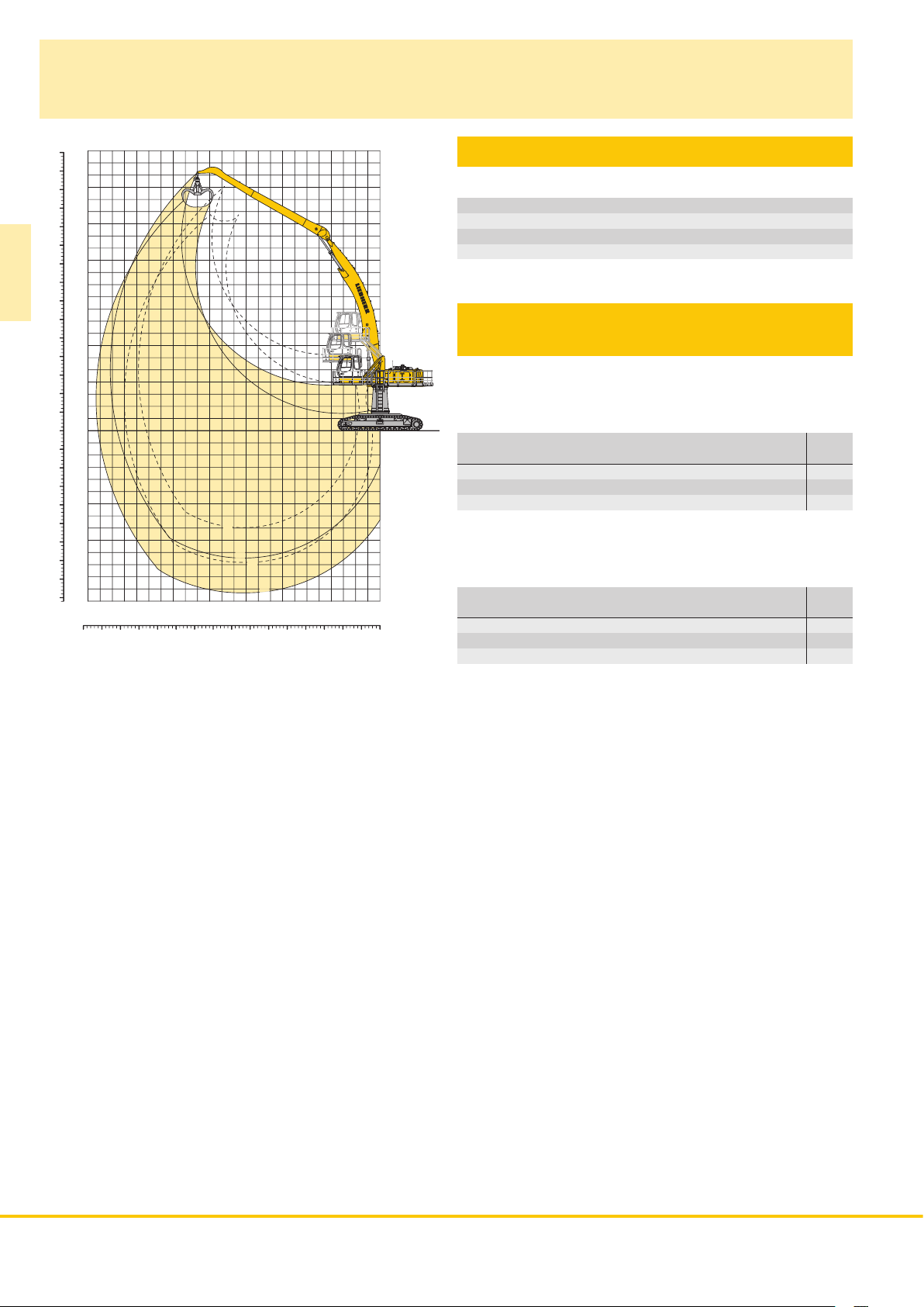
Industrial Attachment
with Industrial-Type Angled Mono Boom 11.50 m
m
ft
22
70
20
60
18
16
50
14
40
12
10
ER 944 C
30
8
20
6
4
10
2
0
0
-2
-10
-4
-6
-20
-30
-40
-10
-12
-14
-8
18
202224
7080 60
1
3
2
4
1416
50
1012
30
40
R0115
24106208
0
0mft
Attachment Envelope
Kinematic variant 3C
1 with industrial stick 9.50 m
2 with industrial stick 12.00 m
3 with industrial stick 9.50 m and grapple model GM 70C
4 with industrial stick 12.00 m and grapple model GM 70C
Operating Weight
and Ground Pressure
Operating weight includes basic machine with hydraulic cab elevation
+ intermediate piece 0.5 m, counterweight 11.0 t, industrial-type
angled mono boom 11.50 m, industrial stick 9.50 m and grapple
model GM 70C with 5 semi-closed tines 0.80 m
Undercarriage HR
Pad width mm 750
Weight kg 74,000
Ground pressure kg/cm
Operating weight includes basic machine with hydraulic cab elevation
+ intermediate piece 0.5 m, counterweight 11.0 t, industrial-type
angled mono boom 11.50 m, industrial stick 12.00 m and grapple
model GM 70C with 5 semi-closed tines 0.80 m
Undercarriage HR
Pad width mm 750
Weight kg 74,700
Ground pressure kg/cm
3
(1,705 kg).
3
(1,705 kg).
2
0.82
2
0.83
26 ER 934 C ER 944 C ER 954 C High Rise
Page 27

Lift Capacities
with Industrial-Type Angled Mono Boom 11.50 m
Industrial Stick 9.50 m (Variant 3C)
3.0 m 4.5 m 6.0 m 7.5 m 9.0 m 10.5 m 12.0 m 13.5 m 15.0 m 16.5 m 18.0 m 19.5 m 21.0 m 22.5 m
Under m carriage m
HR
21.0
19.5
18.0
16.5
15.0
13.5
12.0
10.5
9.0
7.5
6.0
4.5
3.0
1.5
0
– 1.5
– 3.0
– 4.5
– 6.0
– 7.5
– 9.0
HR
HR
HR
HR
HR
HR
HR
HR
HR
HR
HR
HR
HR
HR
HR
HR
HR
HR
HR
HR
4.8* 4.8* 13.4
4.6* 4.6* 14.9
4.4* 4.4* 4.4* 4.4* 16.1
4.4* 4.4* 4.3* 4.3* 4.3* 4.3* 17.1
4.4* 4.4* 4.3* 4.3* 4.3* 4.3* 17.9
4.7* 4.7* 4.5* 4.5* 4.4* 4.4* 4.3* 4.3* 4.2* 4.2* 18.6
4.9* 4.9* 4.6* 4.6* 4.5* 4.5* 4.3* 4.3* 4.2* 4.2* 19.1
5.5* 5.5* 5.1* 5.1* 4.8* 4.8* 4.6* 4.6* 4.4* 4.4* 4.3* 4.3* 19.4
6.5* 6.5* 5.9* 5.9* 5.4* 5.4* 5.0* 5.0* 4.7* 4.7* 4.5* 4.5* 4.3* 4.3* 4.3* 4.3* 19.7
7.1* 7.1* 16.8* 16.8* 12.2* 12.2* 9.7* 9.7* 8.2* 8.2* 7.1* 7.1* 6.3* 6.3* 5.7* 5.7* 5.3* 5.3* 4.9* 4.9* 4.6* 4.6* 4.4* 4.4* 4.3* 4.3* 19.8
1.8* 1.8* 7.7* 7.7* 14.2* 14.2* 11.0* 11.0* 9.0* 9.0* 7.7* 7.7* 6.7* 6.7* 6.0* 6.0* 5.5* 5.5* 5.1* 5.1* 4.7* 4.7* 4.5* 4.5* 4.4* 4.4* 19.8
2.0* 2.0* 5.1* 5.1* 11.6* 11.6* 12.0* 12.0* 9.7* 9.7* 8.2* 8.2* 7.1* 7.1* 6.3* 6.3* 5.7* 5.7* 5.3* 5.3* 4.9* 4.9* 4.5* 4.5* 4.5* 4.5* 19.7
2.8* 2.8* 5.0* 5.0* 9.0* 9.0* 12.9* 12.9* 10.4* 10.4* 8.7* 8.7* 7.5* 7.5* 6.6* 6.6* 5.9* 5.9* 5.4* 5.4* 5.0* 5.0* 4.6* 4.6* 4.6* 4.6* 19.5
3.8* 3.8* 5.4* 5.4* 8.4* 8.4* 13.4* 13.4* 10.8* 10.8* 9.1* 9.1* 7.8* 7.8* 6.9* 6.9* 6.1* 6.1* 5.5* 5.5* 5.1* 5.1* 4.7* 4.7* 19.2
4.6* 4.6* 6.1* 6.1* 8.5* 8.5* 13.1* 13.1* 11.1* 11.1* 9.3* 9.3* 8.0* 8.0* 7.0* 7.0* 6.2* 6.2* 5.6* 5.6* 5.1* 5.1* 4.8* 4.8* 18.7
5.4* 5.4* 6.7* 6.7* 9.0* 9.0* 12.9* 12.9* 11.3* 11.3* 9.5* 9.5* 8.1* 8.1* 7.1* 7.1* 6.3* 6.3* 5.6* 5.6* 5.0* 5.0* 4.9* 4.9* 18.1
7.4* 7.4* 9.5* 9.5* 13.1* 13.1* 11.2* 11.2* 9.4* 9.4* 8.1* 8.1* 7.1* 7.1* 6.2* 6.2* 5.5* 5.5* 5.1* 5.1* 17.4
10.2* 10.2* 13.1* 13.1* 10.9* 10.9* 9.2* 9.2* 7.9* 7.9* 6.9* 6.9* 6.0* 6.0* 5.2* 5.2* 16.5
10.3* 10.3* 8.7* 8.7* 7.5* 7.5* 6.5* 6.5* 6.0* 6.0* 14.1
ER 944 C
Industrial Stick 12.00 m (Variant 3C)
3.0 m 4.5 m 6.0 m 7.5 m 9.0 m 10.5 m 12.0 m 13.5 m 15.0 m 16.5 m 18.0 m 19.5 m 21.0 m 22.5 m
Under m carriage m
HR
21.0
HR
19.5
HR
18.0
HR
16.5
HR
15.0
HR
13.5
HR
12.0
HR
10.5
HR
9.0
HR
7.5
HR
6.0
HR
4.5
HR
3.0
HR
1.5
HR
0
HR
– 1.5
HR
– 3.0
HR
– 4.5
HR
– 6.0
HR
– 7.5
HR
– 9.0
Height Can be slewed through 360° In longitudinal position of undercarriage Max. reach * Limited by hydr. capacity
The lift capacities are stated in metric tonnes (t) on the lifting gear’s stick tip, and can be lifted 360° on firm, level supporting surface. Capacities
are valid for 750 mm track flat pads. Indicated loads are based on ISO 10567 standard and do not exceed 75 % of tipping or 87 % of hydraulic
capacity (indicated via *). Lifting capacity of the excavator is limited by machine stability, hydraulic capacity and maximum permissible load of the
load hook.
According to European Standard, EN 474-5: In the European Union excavators have to be equipped with an overload warning device, a load
diagram and automatic safety check valves on hoist cylinders and stick cylinder(s), when they are used for lifting operations which require the use
of lifting accessories.
3.6* 3.6* 15.2
3.5* 3.5* 3.4* 3.4* 16.7
3.3* 3.3* 3.3* 3.3* 17.9
3.3* 3.3* 3.2* 3.2* 3.2* 3.2* 18.9
3.2* 3.2* 3.2* 3.2* 3.2* 3.2* 3.1* 3.1* 19.7
3.3* 3.3* 3.2* 3.2* 3.2* 3.2* 3.1* 3.1* 20.4
3.3* 3.3* 3.3* 3.3* 3.2* 3.2* 3.1* 3.1* 3.1* 3.1* 21.0
3.5* 3.5* 3.3* 3.3* 3.2* 3.2* 3.2* 3.2* 3.1* 3.1* 21.5
3.8* 3.8* 3.6* 3.6* 3.4* 3.4* 3.3* 3.3* 3.2* 3.2* 3.1* 3.1* 21.8
4.2* 4.2* 4.0* 4.0* 3.8* 3.8* 3.6* 3.6* 3.4* 3.4* 3.3* 3.3* 3.2* 3.2* 22.0
5.0* 5.0* 4.6* 4.6* 4.2* 4.2* 3.9* 3.9* 3.7* 3.7* 3.5* 3.5* 3.4* 3.4* 3.2* 3.2* 22.1
7.0* 7.0* 6.1* 6.1* 5.4* 5.4* 4.9* 4.9* 4.5* 4.5* 4.1* 4.1* 3.9* 3.9* 3.6* 3.6* 3.5* 3.5* 3.3* 3.3* 22.2
5.8* 5.8* 17.2* 17.2* 12.3* 12.3* 9.6* 9.6* 7.9* 7.9* 6.7* 6.7* 5.9* 5.9* 5.2* 5.2* 4.7* 4.7* 4.3* 4.3* 4.0* 4.0* 3.8* 3.8* 3.6* 3.6* 3.4* 3.4* 22.1
3.7* 3.7* 8.0* 8.0* 13.9* 13.9* 10.7* 10.7* 8.6* 8.6* 7.3* 7.3* 6.3* 6.3* 5.6* 5.6* 5.0* 5.0* 4.5* 4.5* 4.2* 4.2* 3.9* 3.9* 3.6* 3.6* 3.5* 3.5* 21.9
3.7* 3.7* 6.3* 6.3* 11.5* 11.5* 11.6* 11.6* 9.3* 9.3* 7.8* 7.8* 6.7* 6.7* 5.9* 5.9* 5.2* 5.2* 4.7* 4.7* 4.3* 4.3* 4.0* 4.0* 3.7* 3.7* 3.6* 3.6* 21.6
4.1* 4.1* 6.0* 6.0* 9.5* 9.5* 12.3* 12.3* 9.9* 9.9* 8.2* 8.2* 7.0* 7.0* 6.1* 6.1* 5.4* 5.4* 4.9* 4.9* 4.4* 4.4* 4.1* 4.1* 3.7* 3.7* 3.7* 3.7* 21.2
4.6* 4.6* 6.2* 6.2* 8.9* 8.9* 12.7* 12.7* 10.2* 10.2* 8.5* 8.5* 7.3* 7.3* 6.3* 6.3* 5.6* 5.6* 5.0* 5.0* 4.5* 4.5* 4.1* 4.1* 3.8* 3.8* 20.7
5.1* 5.1* 6.5* 6.5* 8.8* 8.8* 13.0* 13.0* 10.5* 10.5* 8.7* 8.7* 7.5* 7.5* 6.5* 6.5* 5.7* 5.7* 5.1* 5.1* 4.6* 4.6* 4.1* 4.1* 3.9* 3.9* 20.0
5.5* 5.5* 6.9* 6.9* 9.0* 9.0* 12.8* 12.8* 10.5* 10.5* 8.8* 8.8* 7.5* 7.5* 6.5* 6.5* 5.7* 5.7* 5.1* 5.1* 4.5* 4.5* 4.0* 4.0* 19.2
7.3* 7.3* 9.4* 9.4* 12.7* 12.7* 10.4* 10.4* 8.7* 8.7* 7.5* 7.5* 6.5* 6.5* 5.6* 5.6* 4.9* 4.9* 4.3* 4.3* 4.1* 4.1* 18.3
9.8* 9.8* 12.2* 12.2* 10.0* 10.0* 8.4* 8.4* 7.2* 7.2* 6.2* 6.2* 5.4* 5.4* 4.6* 4.6* 4.4* 4.4* 17.0
ER 934 C ER 944 C ER 954 C High Rise 27
Page 28

The Right Attachment
for Every Application
Industrial-type straight mono boom 8.50 m
Uppercarriage Elevation
ER 954 C
Sorting
grapple
Wood
grapple
Multi-tine
grapple
Stick 7.00 m
Industrial stick 7.80 m
Industrial stick 9.00 m*
Industrial stick 10.00 m*
Industrial-type straight mono boom 10.50 m
Industrial-type straight mono boom 11.50 m*
Industrial-type straight mono boom 12.50 m*
Industrial-type angled mono boom 10.50 m
Undercarriage
Cylindrical cable reel
Spiral cable reel
Rigid cab elevation
Clamshell
bucket
* presented configurations
28 ER 934 C ER 944 C ER 954 C High Rise
Industrial stick 12.00 m*
Hydraulic Cab Elevation
Industrial-type angled mono boom 11.50 m
Hydraulic Cab Elevation
+ Rigid cab elevation
Industrial-type angled mono boom 12.50 m*
Hydraulic Cab Elevation
+ Intermediate Piece
Page 29
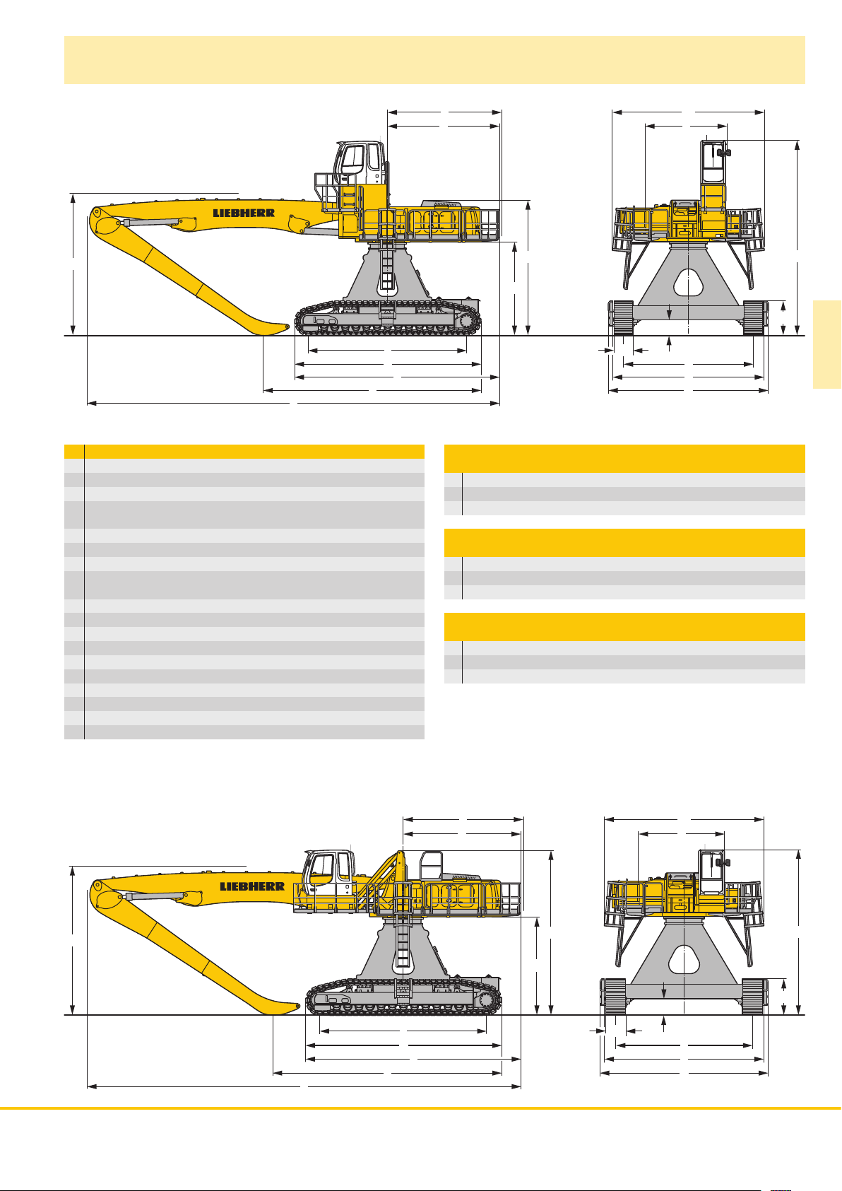
Dimensions
WW
LL
UU
ZZ
VV
XX
mm
A 3,300
A1 5,320
C with Rigid Cab Elevation 7,850
C with Hydraulic Cab Elevation Parallelogram
+ Intermediate Piece 0,5 m 6,350
D 4,510
E 4,600
H with Rigid Cab Elevation 5,465
H with Hydraulic Cab Elevation Parallelogram
+ Intermediate Piece 0,5 m 6,340
K 3,780
L 6,400
P 1,395
Q 640
S 5,250
U 7,540
Z 8,260
N 750
B 6,120
G 6,450
E = Tail radius
EE
DD
HH
KK
NN
A1A1
AA
QQ
SS
BB
GG
Industrial-Type Straight Mono Boom 11.50 m
and Industrial Stick m 9.00 10.00
V mm 8,800 8,200
W mm 5,800 5,800
X mm 16,650 16,650
Industrial-Type Straight Mono Boom 12.50 m
and Industrial Stick m 9.00 10.00
V mm 9,700 8,600
W mm 5,800 5,800
X mm 17,650 17,650
Industrial-Type Angled Mono Boom 12.50 m
and Industrial Stick m 9.00 10.00
V mm * *
W mm 5,800 5,800
X mm 17,100 17,100
* = without stick
CC
PP
R0117
ER 954 C
EE
DD
WW
LL
UU
ZZ
VV
XX
HH
KK
NN
A1A1
AA
QQ
SS
BB
GG
PP
R0116
ER 934 C ER 944 C ER 954 C High Rise 29
CC
Page 30
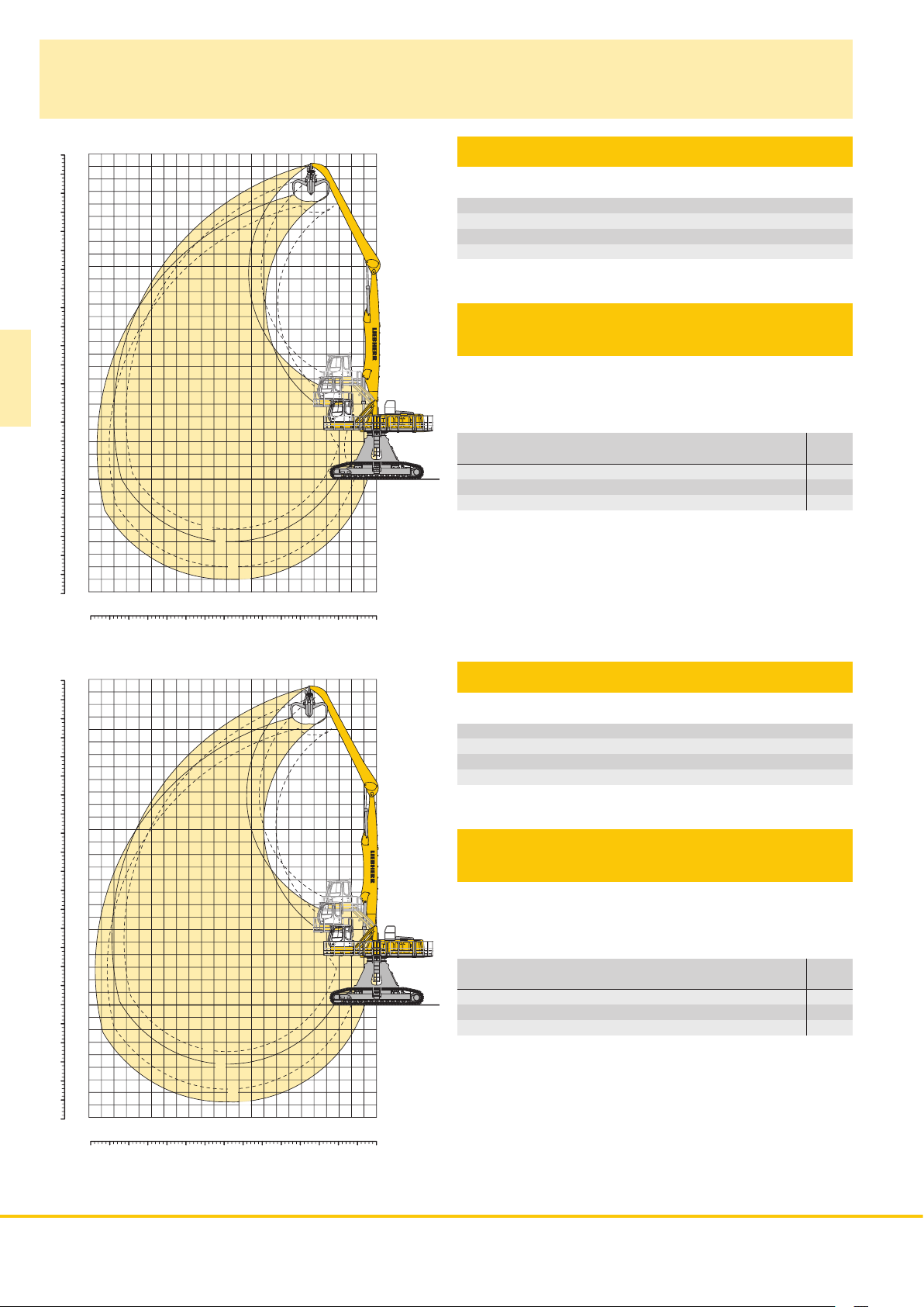
Industrial Attachment
with Industrial-Type Straight Mono Boom 11.50 m
ft
m
26
80
24
22
70
20
60
18
16
50
14
40
12
10
30
8
20
6
ER 954 C
10
-10
-20
-30
4
2
00
-2
-4
-6
-8
1
3
2
4
R0119
Attachment Envelope
Kinematic variants 2A
1 with industrial stick 9.00 m
2 with industrial stick 9.00 m and grapple model GMM 80
3 with industrial stick 10.00 m
4 with industrial stick 10.00 m and grapple model GMM 80
Operating Weight
and Ground Pressure
Operating weight includes basic machine with hydraulic cab elevation
+ intermediate piece 0.5 m, counterweight 14.5 t, industrial-type
straight mono boom 11.50 m, industrial stick 9.00 m and grapple
model GMM 80 with 5 semi-closed tines 1.40 m
Undercarriage HR
Pad width mm 750
Weight kg 95,800
Ground pressure kg/cm
0246810121416182022
3
(2,480 kg).
2
1.00
80
70
60
50
40
30
20
10
-10
-20
-30
0mft10203040506070
m
ft
26
24
22
20
18
16
14
12
10
8
6
4
R0118
Attachment Envelope
Kinematic variants 3B
1 with industrial stick 9.00 m
2 with industrial stick 9.00 m and grapple model GMM 80
3 with industrial stick 10.00 m
4 with industrial stick 10.00 m and grapple model GMM 80
Operating Weight
and Ground Pressure
Operating weight includes basic machine with hydraulic cab elevation
+ intermediate piece 0.5 m, counterweight 14.5 t, industrial-type
straight mono boom 11.50 m, industrial stick 10.00 m and grapple
model GMM 80 with 5 semi-closed tines 1.40 m
3
(2,480 kg).
Undercarriage HR
2
00
-2
-4
-6
-8
1
3
2
4
0246810121416182022
Pad width mm 750
Weight kg 96,200
Ground pressure kg/cm
2
1.00
30 ER 934 C ER 944 C ER 954 C High Rise
0mft10203040506070
Page 31

Lift Capacities
with Industrial-Type Straight Mono Boom 11.50 m
Industrial Stick 9.00 m (Variant 2A)
3.0 m 4.5 m 6.0 m 7.5 m 9.0 m 10.5 m 12.0 m 13.5 m 15.0 m 16.5 m 18.0 m 19.5 m 21.0 m
Under m carriage m
HR
25.5
24.0
22.5
21.0
19.5
18.0
16.5
15.0
13.5
12.0
10.5
9.0
7.5
6.0
4.5
3.0
1.5
0
– 1.5
– 3.0
– 4.5
HR
HR
HR
HR
HR
HR
HR
HR
HR
HR
HR
HR
HR
HR
HR
HR
HR
HR
HR
HR
13.1* 13.1* 5.9
12.9* 12.9* 10.9* 10.9* 9.9* 9.9* 9.6
12.6* 12.6* 11.0* 11.0* 8.6* 8.6* 11.9
13.3* 13.3* 12.3* 12.3* 10.8* 10.8* 8.5* 8.5* 7.9* 7.9* 13.7
13.0* 13.0* 11.6* 11.6* 10.5* 10.5* 7.9* 7.9* 7.4* 7.4* 15.2
13.0* 13.0* 11.6* 11.6* 10.4* 10.4* 9.4* 9.4* 7.0* 7.0* 16.4
13.0* 13.0* 11.6* 11.6* 10.4* 10.4* 9.3* 9.3* 8.4* 8.4* 6.8* 6.8* 17.3
14.6* 14.6* 13.1* 13.1* 11.6* 11.6* 10.4* 10.4* 9.3* 9.3* 8.4* 8.4* 7.1* 7.1* 6.7* 6.7* 18.1
15.2* 15.2* 13.2* 13.2* 11.7* 11.7* 10.4* 10.4* 9.3* 9.3* 8.3* 8.3* 7.4* 7.4* 6.6* 6.6* 18.8
15.6* 15.6* 15.5* 15.5* 13.5* 13.5* 11.8* 11.8* 10.5* 10.5* 9.3* 9.3* 8.3* 8.3* 7.3* 7.3* 6.4* 6.4* 19.3
15.9* 15.9* 18.5* 18.5* 15.9* 15.9* 13.7* 13.7* 11.9* 11.9* 10.5* 10.5* 9.3* 9.3* 8.2* 8.2* 7.2* 7.2* 6.1* 6.1* 6.0* 6.0* 19.6
23.9* 23.9* 24.8* 24.8* 19.7* 19.7* 16.3* 16.3* 13.8* 13.8* 12.0* 12.0* 10.5* 10.5* 9.2* 9.2* 8.1* 8.1* 7.1* 7.1* 5.9* 5.9* 5.6* 5.6* 19.9
9.4* 9.4* 25.5* 25.5* 20.0* 20.0* 16.4* 16.4* 13.9* 13.9* 11.9* 11.9* 10.4* 10.4* 9.1* 9.1* 7.9* 7.9* 6.9* 6.9* 5.7* 5.7* 5.1* 5.1* 20.0
2.5* 2.5* 12.3* 12.3* 19.9* 19.9* 16.3* 16.3* 13.7* 13.7* 11.7* 11.7* 10.2* 10.2* 8.8* 8.8* 7.7* 7.7* 6.6* 6.6* 5.3* 5.3* 4.7* 4.7* 20.0
2.2* 2.2* 7.3* 7.3* 19.2* 19.2* 15.8* 15.8* 13.3* 13.3* 11.4* 11.4* 9.8* 9.8* 8.5* 8.5* 7.3* 7.3* 6.1* 6.1* 4.7* 4.7* 4.2* 4.2* 19.9
2.9* 2.9* 6.5* 6.5* 14.0* 14.0* 14.9* 14.9* 12.6* 12.6* 10.8* 10.8* 9.3* 9.3* 7.9* 7.9* 6.7* 6.7* 5.5* 5.5* 4.0* 4.0* 3.7* 3.7* 19.7
4.0* 4.0* 6.9* 6.9* 12.5* 12.5* 13.5* 13.5* 11.6* 11.6* 9.9* 9.9* 8.5* 8.5* 7.2* 7.2* 6.0* 6.0* 4.7* 4.7* 3.3* 3.3* 19.2
7.7* 7.7* 12.4* 12.4* 11.7* 11.7* 10.1* 10.1* 8.7* 8.7* 7.4* 7.4* 6.2* 6.2* 5.0* 5.0* 3.6* 3.6* 17.9
9.4* 9.4* 8.3* 8.3* 7.2* 7.2* 6.1* 6.1* 4.9* 4.9* 4.3* 4.3* 15.8
ER 954 C
Industrial Stick 10.00 m (Variant 2A)
3.0 m 4.5 m 6.0 m 7.5 m 9.0 m 10.5 m 12.0 m 13.5 m 15.0 m 16.5 m 18.0 m 19.5 m 21.0 m
Under m carriage m
HR
25.5
HR
24.0
HR
22.5
HR
21.0
HR
19.5
HR
18.0
HR
16.5
HR
15.0
HR
13.5
HR
12.0
HR
10.5
HR
9.0
HR
7.5
HR
6.0
HR
4.5
HR
3.0
HR
1.5
HR
0
HR
– 1.5
HR
– 3.0
HR
– 4.5
Height Can be slewed through 360° In longitudinal position of undercarriage Max. reach * Limited by hydr. capacity
The lift capacities are stated in metric tonnes (t) on the lifting gear’s stick tip, and can be lifted 360° on firm, level supporting surface. Capacities
are valid for 750 mm track flat pads. Indicated loads are based on ISO 10567 standard and do not exceed 75 % of tipping or 87 % of hydraulic
capacity (indicated via *). Lifting capacity of the excavator is limited by machine stability, hydraulic capacity and maximum permissible load of the
load hook.
According to European Standard, EN 474-5: In the European Union excavators have to be equipped with an overload warning device, a load
diagram and automatic safety check valves on hoist cylinders and stick cylinder(s), when they are used for lifting operations which require the use
of lifting accessories.
11.4* 11.4* 9.7* 9.7* 8.7
11.2* 11.2* 9.6* 9.6* 8.1* 8.1* 11.5
10.9* 10.9* 9.5* 9.5* 7.3* 7.3* 7.2* 7.2* 13.5
11.5* 11.5* 10.6* 10.6* 9.2* 9.2* 7.0* 7.0* 6.7* 6.7* 15.1
11.9* 11.9* 11.2* 11.2* 10.1* 10.1* 8.8* 8.8* 6.3* 6.3* 16.5
12.2* 12.2* 11.2* 11.2* 10.0* 10.0* 9.1* 9.1* 8.1* 8.1* 6.0* 6.0* 17.6
12.5* 12.5* 11.2* 11.2* 10.0* 10.0* 9.1* 9.1* 8.2* 8.2* 7.0* 7.0* 5.9* 5.9* 18.5
12.6* 12.6* 11.2* 11.2* 10.1* 10.1* 9.1* 9.1* 8.2* 8.2* 7.3* 7.3* 5.8* 5.8* 19.2
12.8* 12.8* 11.3* 11.3* 10.1* 10.1* 9.1* 9.1* 8.2* 8.2* 7.3* 7.3* 6.4* 6.4* 5.7* 5.7* 19.8
13.7* 13.7* 13.0* 13.0* 11.4* 11.4* 10.2* 10.2* 9.1* 9.1* 8.1* 8.1* 7.2* 7.2* 6.3* 6.3* 5.7* 5.7* 20.3
13.9* 13.9* 15.4* 15.4* 13.2* 13.2* 11.6* 11.6* 10.2* 10.2* 9.1* 9.1* 8.1* 8.1* 7.2* 7.2* 6.2* 6.2* 5.4* 5.4* 20.6
15.1* 15.1* 17.9* 17.9* 15.8* 15.8* 13.4* 13.4* 11.7* 11.7* 10.2* 10.2* 9.0* 9.0* 8.0* 8.0* 7.1* 7.1* 6.1* 6.1* 5.0* 5.0* 20.9
33.8* 33.8* 24.8* 24.8* 19.5* 19.5* 16.1* 16.1* 13.6* 13.6* 11.7* 11.7* 10.2* 10.2* 9.0* 9.0* 7.9* 7.9* 6.9* 6.9* 5.9* 5.9* 4.7* 4.7* 21.0
6.0* 6.0* 25.2* 25.2* 19.7* 19.7* 16.1* 16.1* 13.5* 13.5* 11.6* 11.6* 10.1* 10.1* 8.8* 8.8* 7.7* 7.7* 6.6* 6.6* 5.6* 5.6* 4.3* 4.3* 4.3* 4.3* 21.0
0.2* 0.2* 3.3* 3.3* 10.5* 10.5* 19.4* 19.4* 15.8* 15.8* 13.3* 13.3* 11.3* 11.3* 9.8* 9.8* 8.5* 8.5* 7.4* 7.4* 6.3* 6.3* 5.2* 5.2* 3.8* 3.8* 20.9
1.2* 1.2* 3.3* 3.3* 7.6* 7.6* 17.9* 17.9* 15.2* 15.2* 12.8* 12.8* 10.9* 10.9* 9.4* 9.4* 8.1* 8.1* 6.9* 6.9* 5.8* 5.8* 4.6* 4.6* 3.3* 3.3* 20.7
4.0* 4.0* 7.2* 7.2* 13.8* 13.8* 14.1* 14.1* 11.9* 11.9* 10.2* 10.2* 8.7* 8.7* 7.5* 7.5* 6.3* 6.3* 5.2* 5.2* 3.9* 3.9* 2.8* 2.8* 20.4
4.9* 4.9* 7.6* 7.6* 12.7* 12.7* 12.6* 12.6* 10.8* 10.8* 9.2* 9.2* 7.9* 7.9* 6.7* 6.7* 5.5* 5.5* 4.3* 4.3* 3.0* 3.0* 19.3
8.3* 8.3* 12.1* 12.1* 10.6* 10.6* 9.2* 9.2* 7.9* 7.9* 6.7* 6.7* 5.6* 5.6* 4.4* 4.4* 3.4* 3.4* 17.7
8.2* 8.2* 7.3* 7.3* 6.3* 6.3* 5.2* 5.2* 4.3* 4.3* 14.8
ER 934 C ER 944 C ER 954 C High Rise 31
Page 32

Lift Capacities
with Industrial-Type Straight Mono Boom 11.50 m
Industrial Stick 9.00 m (Variant 3B)
3.0 m 4.5 m 6.0 m 7.5 m 9.0 m 10.5 m 12.0 m 13.5 m 15.0 m 16.5 m 18.0 m 19.5 m 21.0 m
Under m carriage m
HR
25.5
13.6* 13.6* 12.3* 12.3* 6.8
13.2* 13.2* 11.5* 11.5* 9.7* 9.7* 10.1
11.8* 11.8* 10.8* 10.8* 9.3* 9.3* 8.5* 8.5* 12.4
11.3* 11.3* 10.4* 10.4* 9.6* 9.6* 9.1* 9.1* 7.8* 7.8* 14.1
10.1* 10.1* 9.4* 9.4* 8.8* 8.8* 8.4* 8.4* 7.3* 7.3* 15.5
10.1* 10.1* 9.3* 9.3* 8.7* 8.7* 8.3* 8.3* 7.5* 7.5* 7.0* 7.0* 16.7
10.1* 10.1* 9.4* 9.4* 8.7* 8.7* 8.2* 8.2* 7.8* 7.8* 6.8* 6.8* 17.6
11.4* 11.4* 10.3* 10.3* 9.5* 9.5* 8.8* 8.8* 8.2* 8.2* 7.8* 7.8* 7.4* 7.4* 6.7* 6.7* 18.4
11.8* 11.8* 10.7* 10.7* 9.7* 9.7* 9.0* 9.0* 8.3* 8.3* 7.8* 7.8* 7.4* 7.4* 6.6* 6.6* 19.0
14.3* 14.3* 12.5* 12.5* 11.1* 11.1* 10.1* 10.1* 9.2* 9.2* 8.5* 8.5* 7.9* 7.9* 7.4* 7.4* 6.6* 6.6* 19.5
16.3* 16.3* 15.5* 15.5* 13.3* 13.3* 11.7* 11.7* 10.4* 10.4* 9.5* 9.5* 8.7* 8.7* 8.0* 8.0* 7.5* 7.5* 6.9* 6.9* 6.6* 6.6* 19.8
28.4* 28.4* 21.1* 21.1* 16.9* 16.9* 14.2* 14.2* 12.3* 12.3* 10.8* 10.8* 9.7* 9.7* 8.9* 8.9* 8.1* 8.1* 7.5* 7.5* 6.9* 6.9* 6.7* 6.7* 20.1
5.4* 5.4* 23.5* 23.5* 18.3* 18.3* 15.1* 15.1* 12.9* 12.9* 11.3* 11.3* 10.0* 10.0* 9.1* 9.1* 8.3* 8.3* 7.6* 7.6* 6.9* 6.9* 6.6* 6.6* 20.2
1.9* 1.9* 9.5* 9.5* 19.5* 19.5* 15.9* 15.9* 13.4* 13.4* 11.6* 11.6* 10.3* 10.3* 9.2* 9.2* 8.4* 8.4* 7.6* 7.6* 6.9* 6.9* 6.5* 6.5* 20.2
2.0* 2.0* 6.4* 6.4* 16.9* 16.9* 16.4* 16.4* 13.8* 13.8* 11.9* 11.9* 10.5* 10.5* 9.4* 9.4* 8.4* 8.4* 7.6* 7.6* 6.8* 6.8* 6.4* 6.4* 20.1
2.8* 2.8* 6.1* 6.1* 12.6* 12.6* 16.7* 16.7* 14.1* 14.1* 12.1* 12.1* 10.6* 10.6* 9.4* 9.4* 8.4* 8.4* 7.5* 7.5* 6.6* 6.6* 6.3* 6.3* 19.8
6.7* 6.7* 11.7* 11.7* 16.7* 16.7* 14.1* 14.1* 12.1* 12.1* 10.6* 10.6* 9.3* 9.3* 8.3* 8.3* 7.3* 7.3* 6.4* 6.4* 19.2
7.6* 7.6* 11.8* 11.8* 16.3* 16.3* 13.8* 13.8* 11.9* 11.9* 10.4* 10.4* 9.1* 9.1* 8.0* 8.0* 7.0* 7.0* 17.8
15.5* 15.5* 13.2* 13.2* 11.4* 11.4* 9.9* 9.9* 8.6* 8.6* 8.3* 8.3* 15.5
ER 954 C
24.0
22.5
21.0
19.5
18.0
16.5
15.0
13.5
12.0
10.5
9.0
7.5
6.0
4.5
3.0
1.5
0
– 1.5
– 3.0
– 4.5
HR
HR
HR
HR
HR
HR
HR
HR
HR
HR
HR
HR
HR
HR
HR
HR
HR
HR
HR
HR
Industrial Stick 10.00 m (Variant 3B)
3.0 m 4.5 m 6.0 m 7.5 m 9.0 m 10.5 m 12.0 m 13.5 m 15.0 m 16.5 m 18.0 m 19.5 m 21.0 m
Under m carriage m
HR
25.5
HR
24.0
HR
22.5
HR
21.0
HR
19.5
HR
18.0
HR
16.5
HR
15.0
HR
13.5
HR
12.0
HR
10.5
HR
9.0
HR
7.5
HR
6.0
HR
4.5
HR
3.0
HR
1.5
HR
0
HR
– 1.5
HR
– 3.0
HR
– 4.5
Height Can be slewed through 360° In longitudinal position of undercarriage Max. reach * Limited by hydr. capacity
The lift capacities are stated in metric tonnes (t) on the lifting gear’s stick tip, and can be lifted 360° on firm, level supporting surface. Capacities
are valid for 750 mm track flat pads. Indicated loads are based on ISO 10567 standard and do not exceed 75 % of tipping or 87 % of hydraulic
capacity (indicated via *). Lifting capacity of the excavator is limited by machine stability, hydraulic capacity and maximum permissible load of the
load hook.
According to European Standard, EN 474-5: In the European Union excavators have to be equipped with an overload warning device, a load
diagram and automatic safety check valves on hoist cylinders and stick cylinder(s), when they are used for lifting operations which require the use
of lifting accessories.
11.8* 11.8* 9.9* 9.9* 9.4* 9.4* 9.3
11.5* 11.5* 10.0* 10.0* 7.9* 7.9* 12.0
10.0* 10.0* 9.3* 9.3* 8.0* 8.0* 7.1* 7.1* 13.9
9.6* 9.6* 8.9* 8.9* 8.4* 8.4* 7.6* 7.6* 6.6* 6.6* 15.5
9.4* 9.4* 8.8* 8.8* 8.2* 8.2* 7.8* 7.8* 6.9* 6.9* 6.3* 6.3* 16.8
9.4* 9.4* 8.7* 8.7* 8.2* 8.2* 7.7* 7.7* 7.3* 7.3* 6.0* 6.0* 17.8
9.4* 9.4* 8.7* 8.7* 8.2* 8.2* 7.7* 7.7* 7.3* 7.3* 6.9* 6.9* 5.8* 5.8* 18.7
9.6* 9.6* 8.9* 8.9* 8.3* 8.3* 7.7* 7.7* 7.3* 7.3* 6.9* 6.9* 5.7* 5.7* 19.4
9.9* 9.9* 9.1* 9.1* 8.4* 8.4* 7.8* 7.8* 7.3* 7.3* 6.9* 6.9* 6.6* 6.6* 5.7* 5.7* 20.0
11.6* 11.6* 10.4* 10.4* 9.4* 9.4* 8.6* 8.6* 8.0* 8.0* 7.5* 7.5* 7.0* 7.0* 6.6* 6.6* 5.7* 5.7* 20.5
14.0* 14.0* 12.3* 12.3* 10.9* 10.9* 9.8* 9.8* 8.9* 8.9* 8.2* 8.2* 7.6* 7.6* 7.1* 7.1* 6.6* 6.6* 5.7* 5.7* 20.8
11.1* 11.1* 15.9* 15.9* 15.6* 15.6* 13.2* 13.2* 11.5* 11.5* 10.2* 10.2* 9.2* 9.2* 8.4* 8.4* 7.7* 7.7* 7.1* 7.1* 6.6* 6.6* 5.9* 5.9* 5.7* 5.7* 21.0
29.7* 29.7* 21.6* 21.6* 17.1* 17.1* 14.2* 14.2* 12.2* 12.2* 10.7* 10.7* 9.5* 9.5* 8.6* 8.6* 7.9* 7.9* 7.2* 7.2* 6.7* 6.7* 6.1* 6.1* 5.8* 5.8* 21.1
4.2* 4.2* 21.8* 21.8* 18.4* 18.4* 15.0* 15.0* 12.7* 12.7* 11.1* 11.1* 9.8* 9.8* 8.8* 8.8* 8.0* 8.0* 7.3* 7.3* 6.7* 6.7* 6.0* 6.0* 5.9* 5.9* 21.1
0.2* 0.2* 2.8* 2.8* 8.7* 8.7* 19.4* 19.4* 15.7* 15.7* 13.2* 13.2* 11.4* 11.4* 10.1* 10.1* 9.0* 9.0* 8.1* 8.1* 7.3* 7.3* 6.6* 6.6* 5.9* 5.9* 5.9* 5.9* 21.0
1.2* 1.2* 3.1* 3.1* 6.9* 6.9* 15.4* 15.4* 16.2* 16.2* 13.6* 13.6* 11.7* 11.7* 10.2* 10.2* 9.1* 9.1* 8.1* 8.1* 7.3* 7.3* 6.5* 6.5* 5.8* 5.8* 20.8
3.9* 3.9* 6.9* 6.9* 12.6* 12.6* 16.3* 16.3* 13.7* 13.7* 11.8* 11.8* 10.3* 10.3* 9.1* 9.1* 8.1* 8.1* 7.2* 7.2* 6.3* 6.3* 5.7* 5.7* 20.4
7.4* 7.4* 12.0* 12.0* 16.2* 16.2* 13.6* 13.6* 11.7* 11.7* 10.2* 10.2* 9.0* 9.0* 7.9* 7.9* 7.0* 7.0* 6.1* 6.1* 19.3
12.2* 12.2* 15.7* 15.7* 13.3* 13.3* 11.4* 11.4* 9.9* 9.9* 8.7* 8.7* 7.6* 7.6* 6.8* 6.8* 17.5
12.6* 12.6* 10.8* 10.8* 9.4* 9.4* 8.9* 8.9* 14.1
32 ER 934 C ER 944 C ER 954 C High Rise
Page 33

Industrial Attachment
with Industrial-Type Straight Mono Boom 12.50 m
m
-10
-20
-30
ft
26
80
24
22
70
20
60
18
16
50
14
40
12
10
30
8
20
6
4
10
2
00
-2
-4
-6
-8
1
3
2
4
R0120
Attachment Envelope
Kinematic variants 2A
1 with industrial stick 9.00 m
2 with industrial stick 9.00 m and grapple model GMM 80
3 with industrial stick 10.00 m
4 with industrial stick 10.00 m and grapple model GMM 80
Operating Weight
and Ground Pressure
Operating weight includes basic machine with hydraulic cab elevation
+ intermediate piece 0.5 m, counterweight 14.5 t, industrial-type
straight mono boom 12.50 m, industrial stick 9.00 m and grapple
model GMM 80 with 5 semi-closed tines 1.10 m
Undercarriage HR
Pad width mm 750
Weight kg 96,200
Ground pressure kg/cm
0246810121416182024 22
3
(2,400 kg).
2
1.00
ER 954 C
-10
-20
-30
0mft1020304050607080
m
ft
26
80
24
22
70
20
60
18
16
50
14
40
12
10
30
8
20
6
4
10
2
00
-2
-4
-6
-8
1
3
2
4
R0121
Attachment Envelope
Kinematic variants 3B
1 with industrial stick 9.00 m
2 with industrial stick 9.00 m and grapple model GMM 80
3 with industrial stick 10.00 m
4 with industrial stick 10.00 m and grapple model GMM 80
Operating Weight
and Ground Pressure
Operating weight includes basic machine with hydraulic cab elevation
+ intermediate piece 0.5 m, counterweight 14.5 t, industrial-type
straight mono boom 12.50 m, industrial stick 10.00 m and grapple
model GMM 80 with 5 semi-closed tines 1.10 m
Undercarriage HR
Pad width mm 750
Weight kg 96,600
Ground pressure kg/cm
0246810121416182024 22
3
(2,400 kg).
2
1.00
0mft1020304050607080
ER 934 C ER 944 C ER 954 C High Rise 33
Page 34

Lift Capacities
with Industrial-Type Straight Mono Boom 12.50 m
Industrial Stick 9.00 m (Variant 2A)
3.0 m 4.5 m 6.0 m 7.5 m 9.0 m 10.5 m 12.0 m 13.5 m 15.0 m 16.5 m 18.0 m 19.5 m 21.0 m
Under m carriage m
HR
25.5
12.4* 12.4* 10.7* 10.7* 8.7
12.3* 12.3* 10.6* 10.6* 9.0* 9.0* 11.5
13.1* 13.1* 12.1* 12.1* 10.6* 10.6* 8.2* 8.2* 8.1* 8.1* 13.5
13.6* 13.6* 12.9* 12.9* 11.4* 11.4* 10.2* 10.2* 7.9* 7.9* 7.6* 7.6* 15.1
12.9* 12.9* 11.4* 11.4* 10.1* 10.1* 9.0* 9.0* 7.2* 7.2* 16.5
12.8* 12.8* 11.3* 11.3* 10.1* 10.1* 9.0* 9.0* 8.1* 8.1* 6.9* 6.9* 17.6
14.4* 14.4* 12.9* 12.9* 11.3* 11.3* 10.1* 10.1* 9.0* 9.0* 8.1* 8.1* 7.1* 7.1* 6.8* 6.8* 18.5
15.0* 15.0* 13.0* 13.0* 11.4* 11.4* 10.1* 10.1* 9.0* 9.0* 8.0* 8.0* 7.1* 7.1* 6.3* 6.3* 19.2
15.0* 15.0* 15.2* 15.2* 13.1* 13.1* 11.5* 11.5* 10.1* 10.1* 9.0* 9.0* 8.0* 8.0* 7.1* 7.1* 6.1* 6.1* 5.9* 5.9* 19.8
14.7* 14.7* 17.0* 17.0* 15.5* 15.5* 13.2* 13.2* 11.5* 11.5* 10.1* 10.1* 9.0* 9.0* 7.9* 7.9* 7.0* 7.0* 6.1* 6.1* 5.5* 5.5* 20.3
16.0* 16.0* 20.3* 20.3* 19.0* 19.0* 15.7* 15.7* 13.4* 13.4* 11.5* 11.5* 10.1* 10.1* 8.9* 8.9* 7.9* 7.9* 6.9* 6.9* 6.0* 6.0* 5.1* 5.1* 20.6
19.5* 19.5* 24.6* 24.6* 19.3* 19.3* 15.9* 15.9* 13.4* 13.4* 11.5* 11.5* 10.0* 10.0* 8.8* 8.8* 7.7* 7.7* 6.8* 6.8* 5.8* 5.8* 4.7* 4.7* 20.9
11.2* 11.2* 19.3* 19.3* 15.8* 15.8* 13.2* 13.2* 11.3* 11.3* 9.8* 9.8* 8.6* 8.6* 7.5* 7.5* 6.5* 6.5* 5.5* 5.5* 4.3* 4.3* 21.0
4.6* 4.6* 16.4* 16.4* 15.4* 15.4* 12.9* 12.9* 11.1* 11.1* 9.6* 9.6* 8.3* 8.3* 7.2* 7.2* 6.2* 6.2* 5.2* 5.2* 3.9* 3.9* 3.9* 3.9* 21.0
0.5* 0.5* 3.7* 3.7* 10.0* 10.0* 14.6* 14.6* 12.3* 12.3* 10.6* 10.6* 9.1* 9.1* 7.9* 7.9* 6.8* 6.8* 5.8* 5.8* 4.8* 4.8* 3.5* 3.5* 20.9
1.5* 1.5* 4.1* 4.1* 8.5* 8.5* 13.4* 13.4* 11.5* 11.5* 9.9* 9.9* 8.5* 8.5* 7.4* 7.4* 6.3* 6.3* 5.3* 5.3* 4.2* 4.2* 3.0* 3.0* 20.7
4.9* 4.9* 8.5* 8.5* 11.8* 11.8* 10.3* 10.3* 9.0* 9.0* 7.8* 7.8* 6.7* 6.7* 5.6* 5.6* 4.6* 4.6* 3.4* 3.4* 2.6* 2.6* 20.2
9.0* 9.0* 9.9* 9.9* 8.9* 8.9* 7.8* 7.8* 6.7* 6.7* 5.7* 5.7* 4.7* 4.7* 3.7* 3.7* 2.9* 2.9* 18.9
7.7* 7.7* 7.1* 7.1* 6.3* 6.3* 5.4* 5.4* 4.6* 4.6* 3.6* 3.6* 3.4* 3.4* 16.8
ER 954 C
24.0
22.5
21.0
19.5
18.0
16.5
15.0
13.5
12.0
10.5
9.0
7.5
6.0
4.5
3.0
1.5
0
– 1.5
– 3.0
– 4.5
HR
HR
HR
HR
HR
HR
HR
HR
HR
HR
HR
HR
HR
HR
HR
HR
HR
HR
HR
HR
Industrial Stick 10.00 m (Variant 2A)
3.0 m 4.5 m 6.0 m 7.5 m 9.0 m 10.5 m 12.0 m 13.5 m 15.0 m 16.5 m 18.0 m 19.5 m 21.0 m
Under m carriage m
HR
25.5
HR
24.0
HR
22.5
HR
21.0
HR
19.5
HR
18.0
HR
16.5
HR
15.0
HR
13.5
HR
12.0
HR
10.5
HR
9.0
HR
7.5
HR
6.0
HR
4.5
HR
3.0
HR
1.5
HR
0
HR
– 1.5
HR
– 3.0
HR
– 4.5
Height Can be slewed through 360° In longitudinal position of undercarriage Max. reach * Limited by hydr. capacity
The lift capacities are stated in metric tonnes (t) on the lifting gear’s stick tip, and can be lifted 360° on firm, level supporting surface. Capacities
are valid for 750 mm track flat pads. Indicated loads are based on ISO 10567 standard and do not exceed 75 % of tipping or 87 % of hydraulic
capacity (indicated via *). Lifting capacity of the excavator is limited by machine stability, hydraulic capacity and maximum permissible load of the
load hook.
According to European Standard, EN 474-5: In the European Union excavators have to be equipped with an overload warning device, a load
diagram and automatic safety check valves on hoist cylinders and stick cylinder(s), when they are used for lifting operations which require the use
of lifting accessories.
10.7* 10.7* 10.6* 10.6* 7.6
10.9* 10.9* 9.1* 9.1* 8.5* 8.5* 10.9
11.7* 11.7* 10.7* 10.7* 9.2* 9.2* 7.5* 7.5* 13.2
11.4* 11.4* 10.5* 10.5* 9.1* 9.1* 6.9* 6.9* 15.0
11.8* 11.8* 11.1* 11.1* 9.9* 9.9* 8.8* 8.8* 6.5* 6.5* 16.5
12.1* 12.1* 11.0* 11.0* 9.8* 9.8* 8.8* 8.8* 7.9* 7.9* 6.2* 6.2* 17.7
12.4* 12.4* 11.0* 11.0* 9.8* 9.8* 8.8* 8.8* 7.9* 7.9* 7.0* 7.0* 6.0* 6.0* 18.7
12.5* 12.5* 11.0* 11.0* 9.8* 9.8* 8.8* 8.8* 7.9* 7.9* 7.0* 7.0* 6.0* 6.0* 5.8* 5.8* 19.6
12.6* 12.6* 11.1* 11.1* 9.8* 9.8* 8.8* 8.8* 7.8* 7.8* 7.0* 7.0* 6.2* 6.2* 5.7* 5.7* 20.3
13.4* 13.4* 12.7* 12.7* 11.1* 11.1* 9.8* 9.8* 8.8* 8.8* 7.8* 7.8* 7.0* 7.0* 6.1* 6.1* 5.3* 5.3* 20.8
13.2* 13.2* 14.7* 14.7* 12.9* 12.9* 11.2* 11.2* 9.9* 9.9* 8.7* 8.7* 7.8* 7.8* 6.9* 6.9* 6.1* 6.1* 5.2* 5.2* 4.9* 4.9* 21.3
13.1* 13.1* 15.8* 15.8* 15.3* 15.3* 13.0* 13.0* 11.3* 11.3* 9.9* 9.9* 8.7* 8.7* 7.7* 7.7* 6.8* 6.8* 6.0* 6.0* 5.1* 5.1* 4.6* 4.6* 21.6
19.8* 19.8* 22.9* 22.9* 18.9* 18.9* 15.5* 15.5* 13.1* 13.1* 11.3* 11.3* 9.8* 9.8* 8.6* 8.6* 7.6* 7.6* 6.7* 6.7* 5.8* 5.8* 4.9* 4.9* 4.3* 4.3* 21.8
6.1* 6.1* 24.3* 24.3* 19.0* 19.0* 15.5* 15.5* 13.1* 13.1* 11.2* 11.2* 9.7* 9.7* 8.5* 8.5* 7.4* 7.4* 6.5* 6.5* 5.6* 5.6* 4.7* 4.7* 3.9* 3.9* 22.0
1.4* 1.4* 8.5* 8.5* 18.7* 18.7* 15.3* 15.3* 12.8* 12.8* 11.0* 11.0* 9.5* 9.5* 8.3* 8.3* 7.2* 7.2* 6.3* 6.3* 5.3* 5.3* 4.4* 4.4* 3.5* 3.5* 22.0
1.3* 1.3* 5.1* 5.1* 13.9* 13.9* 14.7* 14.7* 12.4* 12.4* 10.6* 10.6* 9.1* 9.1* 7.9* 7.9* 6.9* 6.9* 5.9* 5.9* 5.0* 5.0* 3.9* 3.9* 3.1* 3.1* 21.9
1.9* 1.9* 4.6* 4.6* 10.0* 10.0* 13.8* 13.8* 11.7* 11.7* 10.0* 10.0* 8.7* 8.7* 7.5* 7.5* 6.4* 6.4* 5.5* 5.5* 4.5* 4.5* 3.4* 3.4* 2.7* 2.7* 21.7
2.8* 2.8* 5.0* 5.0* 9.0* 9.0* 12.5* 12.5* 10.7* 10.7* 9.3* 9.3* 8.0* 8.0* 6.9* 6.9* 5.9* 5.9* 4.9* 4.9* 3.9* 3.9* 2.6* 2.6* 2.2* 2.2* 21.4
5.7* 5.7* 9.0* 9.0* 10.9* 10.9* 9.5* 9.5* 8.2* 8.2* 7.1* 7.1* 6.1* 6.1* 5.1* 5.1* 4.1* 4.1* 3.0* 3.0* 2.3* 2.3* 20.3
9.5* 9.5* 8.9* 8.9* 7.9* 7.9* 6.9* 6.9* 6.0* 6.0* 5.1* 5.1* 4.1* 4.1* 3.1* 3.1* 2.6* 2.6* 18.7
6.0* 6.0* 5.4* 5.4* 4.6* 4.6* 3.8* 3.8* 3.4* 3.4* 15.8
34 ER 934 C ER 944 C ER 954 C High Rise
Page 35

Lift Capacities
with Industrial-Type Straight Mono Boom 12.50 m
Industrial Stick 9.00 m (Variant 3B)
3.0 m 4.5 m 6.0 m 7.5 m 9.0 m 10.5 m 12.0 m 13.5 m 15.0 m 16.5 m 18.0 m 19.5 m 21.0 m
Under m carriage m
HR
25.5
HR
24.0
HR
22.5
HR
21.0
HR
19.5
HR
18.0
HR
16.5
HR
15.0
HR
13.5
HR
12.0
HR
10.5
HR
9.0
HR
7.5
HR
6.0
HR
4.5
HR
3.0
HR
1.5
HR
0
HR
– 1.5
HR
– 3.0
HR
– 4.5
14.3* 14.3* 5.0
12.9* 12.9* 10.9* 10.9* 10.3* 10.3* 9.3
11.9* 11.9* 10.7* 10.7* 8.9* 8.9* 12.0
11.4* 11.4* 10.3* 10.3* 9.4* 9.4* 8.7* 8.7* 8.0* 8.0* 13.9
10.0* 10.0* 9.2* 9.2* 8.5* 8.5* 8.0* 8.0* 7.5* 7.5* 15.5
9.9* 9.9* 9.1* 9.1* 8.4* 8.4* 7.8* 7.8* 7.4* 7.4* 7.1* 7.1* 16.8
9.9* 9.9* 9.1* 9.1* 8.4* 8.4* 7.8* 7.8* 7.3* 7.3* 6.9* 6.9* 17.9
11.2* 11.2* 10.1* 10.1* 9.1* 9.1* 8.4* 8.4* 7.8* 7.8* 7.3* 7.3* 6.8* 6.8* 6.7* 6.7* 18.7
11.6* 11.6* 10.3* 10.3* 9.3* 9.3* 8.5* 8.5* 7.8* 7.8* 7.3* 7.3* 6.8* 6.8* 6.5* 6.5* 19.5
13.9* 13.9* 12.0* 12.0* 10.6* 10.6* 9.5* 9.5* 8.7* 8.7* 8.0* 8.0* 7.4* 7.4* 6.9* 6.9* 6.4* 6.4* 6.3* 6.3* 20.0
14.8* 14.8* 14.8* 14.8* 12.6* 12.6* 11.0* 11.0* 9.8* 9.8* 8.9* 8.9* 8.1* 8.1* 7.5* 7.5* 6.9* 6.9* 6.4* 6.4* 6.1* 6.1* 20.5
9.3* 9.3* 17.5* 17.5* 19.8* 19.8* 15.9* 15.9* 13.3* 13.3* 11.5* 11.5* 10.2* 10.2* 9.1* 9.1* 8.3* 8.3* 7.6* 7.6* 7.0* 7.0* 6.5* 6.5* 6.0* 6.0* 20.8
7.0* 7.0* 21.8* 21.8* 17.1* 17.1* 14.1* 14.1* 12.0* 12.0* 10.5* 10.5* 9.3* 9.3* 8.4* 8.4* 7.7* 7.7* 7.0* 7.0* 6.5* 6.5* 5.9* 5.9* 5.9* 5.9* 21.0
7.7* 7.7* 18.1* 18.1* 14.8* 14.8* 12.5* 12.5* 10.8* 10.8* 9.6* 9.6* 8.6* 8.6* 7.8* 7.8* 7.1* 7.1* 6.5* 6.5* 5.9* 5.9* 5.8* 5.8* 21.1
3.8* 3.8* 13.0* 13.0* 15.3* 15.3* 12.9* 12.9* 11.1* 11.1* 9.8* 9.8* 8.7* 8.7* 7.8* 7.8* 7.1* 7.1* 6.5* 6.5* 5.8* 5.8* 5.7* 5.7* 21.1
0.4* 0.4* 3.3* 3.3* 8.8* 8.8* 15.7* 15.7* 13.1* 13.1* 11.3* 11.3* 9.9* 9.9* 8.8* 8.8* 7.9* 7.9* 7.1* 7.1* 6.4* 6.4* 5.6* 5.6* 5.6* 5.6* 21.0
3.9* 3.9* 7.9* 7.9* 15.8* 15.8* 13.2* 13.2* 11.4* 11.4* 9.9* 9.9* 8.8* 8.8* 7.9* 7.9* 7.0* 7.0* 6.3* 6.3* 5.5* 5.5* 20.8
4.7* 4.7* 8.1* 8.1* 14.4* 14.4* 13.1* 13.1* 11.3* 11.3* 9.9* 9.9* 8.7* 8.7* 7.7* 7.7* 6.9* 6.9* 6.0* 6.0* 5.6* 5.6* 20.2
8.7* 8.7* 14.1* 14.1* 12.8* 12.8* 11.0* 11.0* 9.6* 9.6* 8.5* 8.5* 7.5* 7.5* 6.6* 6.6* 6.0* 6.0* 18.8
12.2* 12.2* 10.6* 10.6* 9.2* 9.2* 8.1* 8.1* 7.1* 7.1* 16.5
ER 954 C
Industrial Stick 10.00 m (Variant 3B)
3.0 m 4.5 m 6.0 m 7.5 m 9.0 m 10.5 m 12.0 m 13.5 m 15.0 m 16.5 m 18.0 m 19.5 m 21.0 m
Under m carriage m
HR
25.5
HR
24.0
HR
22.5
HR
21.0
HR
19.5
HR
18.0
HR
16.5
HR
15.0
HR
13.5
HR
12.0
HR
10.5
HR
9.0
HR
7.5
HR
6.0
HR
4.5
HR
3.0
HR
1.5
HR
0
HR
– 1.5
HR
– 3.0
HR
– 4.5
Height Can be slewed through 360° In longitudinal position of undercarriage Max. reach * Limited by hydr. capacity
The lift capacities are stated in metric tonnes (t) on the lifting gear’s stick tip, and can be lifted 360° on firm, level supporting surface. Capacities
are valid for 750 mm track flat pads. Indicated loads are based on ISO 10567 standard and do not exceed 75 % of tipping or 87 % of hydraulic
capacity (indicated via *). Lifting capacity of the excavator is limited by machine stability, hydraulic capacity and maximum permissible load of the
load hook.
According to European Standard, EN 474-5: In the European Union excavators have to be equipped with an overload warning device, a load
diagram and automatic safety check valves on hoist cylinders and stick cylinder(s), when they are used for lifting operations which require the use
of lifting accessories.
11.3* 11.3* 10.2* 10.2* 8.3
11.2* 11.2* 9.7* 9.7* 8.3* 8.3* 11.4
10.0* 10.0* 9.1* 9.1* 7.6* 7.6* 7.4* 7.4* 13.6
9.6* 9.6* 8.8* 8.8* 8.1* 8.1* 7.5* 7.5* 6.8* 6.8* 15.4
9.4* 9.4* 8.6* 8.6* 8.0* 8.0* 7.4* 7.4* 7.0* 7.0* 6.4* 6.4* 16.8
9.3* 9.3* 8.5* 8.5* 7.9* 7.9* 7.3* 7.3* 6.9* 6.9* 6.1* 6.1* 6.1* 6.1* 18.0
9.4* 9.4* 8.5* 8.5* 7.9* 7.9* 7.3* 7.3* 6.8* 6.8* 6.5* 6.5* 5.9* 5.9* 19.0
9.5* 9.5* 8.6* 8.6* 7.9* 7.9* 7.3* 7.3* 6.8* 6.8* 6.4* 6.4* 6.1* 6.1* 5.8* 5.8* 19.8
9.7* 9.7* 8.8* 8.8* 8.0* 8.0* 7.4* 7.4* 6.9* 6.9* 6.4* 6.4* 6.1* 6.1* 5.7* 5.7* 20.5
11.3* 11.3* 10.0* 10.0* 9.0* 9.0* 8.2* 8.2* 7.5* 7.5* 7.0* 7.0* 6.5* 6.5* 6.1* 6.1* 5.7* 5.7* 5.7* 5.7* 21.1
13.2* 13.2* 11.8* 11.8* 10.4* 10.4* 9.3* 9.3* 8.4* 8.4* 7.7* 7.7* 7.1* 7.1* 6.5* 6.5* 6.1* 6.1* 5.7* 5.7* 5.5* 5.5* 21.5
13.4* 13.4* 14.8* 14.8* 12.5* 12.5* 10.9* 10.9* 9.6* 9.6* 8.6* 8.6* 7.8* 7.8* 7.2* 7.2* 6.6* 6.6* 6.1* 6.1* 5.7* 5.7* 5.4* 5.4* 21.8
27.4* 27.4* 20.1* 20.1* 16.0* 16.0* 13.3* 13.3* 11.4* 11.4* 10.0* 10.0* 8.9* 8.9* 8.0* 8.0* 7.3* 7.3* 6.7* 6.7* 6.2* 6.2* 5.7* 5.7* 5.3* 5.3* 22.0
3.4* 3.4* 22.0* 22.0* 17.1* 17.1* 14.0* 14.0* 11.9* 11.9* 10.3* 10.3* 9.1* 9.1* 8.2* 8.2* 7.4* 7.4* 6.8* 6.8* 6.2* 6.2* 5.7* 5.7* 5.3* 5.3* 22.1
0.9* 0.9* 6.6* 6.6* 18.0* 18.0* 14.6* 14.6* 12.3* 12.3* 10.6* 10.6* 9.3* 9.3* 8.3* 8.3* 7.5* 7.5* 6.8* 6.8* 6.2* 6.2* 5.6* 5.6* 5.2* 5.2* 22.1
1.1* 1.1* 4.4* 4.4* 11.7* 11.7* 15.1* 15.1* 12.6* 12.6* 10.9* 10.9* 9.5* 9.5* 8.4* 8.4* 7.6* 7.6* 6.8* 6.8* 6.2* 6.2* 5.6* 5.6* 5.1* 5.1* 22.0
1.8* 1.8* 4.3* 4.3* 9.0* 9.0* 15.3* 15.3* 12.8* 12.8* 11.0* 11.0* 9.6* 9.6* 8.5* 8.5* 7.6* 7.6* 6.8* 6.8* 6.1* 6.1* 5.4* 5.4* 5.0* 5.0* 21.8
2.7* 2.7* 4.8* 4.8* 8.5* 8.5* 15.3* 15.3* 12.8* 12.8* 11.0* 11.0* 9.6* 9.6* 8.5* 8.5* 7.5* 7.5* 6.7* 6.7* 6.0* 6.0* 5.2* 5.2* 4.9* 4.9* 21.4
5.6* 5.6* 8.7* 8.7* 14.5* 14.5* 12.6* 12.6* 10.9* 10.9* 9.5* 9.5* 8.3* 8.3* 7.4* 7.4* 6.5* 6.5* 5.7* 5.7* 5.3* 5.3* 20.3
9.3* 9.3* 14.3* 14.3* 12.2* 12.2* 10.5* 10.5* 9.2* 9.2* 8.1* 8.1* 7.1* 7.1* 6.2* 6.2* 5.9* 5.9* 18.5
10.0* 10.0* 8.7* 8.7* 7.6* 7.6* 7.5* 7.5* 15.1
ER 934 C ER 944 C ER 954 C High Rise 35
Page 36

Industrial Attachment
with Industrial-Type Angled Mono Boom 12.50 m
ft
m
22
70
20
60
18
16
50
14
40
12
10
30
8
20
6
4
10
2
ER 954 C
-10
-20
-30
-40
-10
-12
00
-2
-4
-6
-8
1
3
2
4
R0122
Attachment Envelope
Kinematic variant 3C
1 with industrial stick 9.00 m
2 with industrial stick 10.00 m
3 with industrial stick 9.00 m and grapple model GMM 80
4 with industrial stick 10.00 m and grapple model GMM 80
Operating Weight
and Ground Pressure
Operating weight includes basic machine with hydraulic cab elevation
+ intermediate piece 0.5 m, counterweight 14.5 t, industrial-type
angled mono boom 12.50 m, industrial stick 9.00 m and grapple
model GMM 80 with 5 semi-closed tines 1.10 m
Undercarriage HR
Pad width mm 750
Weight kg 96,600
Ground pressure kg/cm
Operating weight includes basic machine with hydraulic cab elevation
+ intermediate piece 0.5 m, counterweight 14.5 t, industrial-type
angled mono boom 12.50 m, industrial stick 10.00 m and grapple
model GMM 80 with 5 semi-closed tines 1.10 m
0246810121416182024 22
Undercarriage HR
3
(2,400 kg).
3
(2,400 kg).
2
1.01
0mft1020304050607080
Pad width mm 750
Weight kg 97,000
Ground pressure kg/cm
2
1.01
36 ER 934 C ER 944 C ER 954 C High Rise
Page 37

Lift Capacities
with Industrial-Type Angled Mono Boom 12.50 m
Industrial Stick 9.00 m (Variant 3C)
3.0 m 4.5 m 6.0 m 7.5 m 9.0 m 10.5 m 12.0 m 13.5 m 15.0 m 16.5 m 18.0 m 19.5 m 21.0 m
Under m carriage m
HR
21.0
19.5
18.0
16.5
15.0
13.5
12.0
10.5
9.0
7.5
6.0
4.5
3.0
1.5
0
– 1.5
– 3.0
– 4.5
– 6.0
– 7.5
HR
HR
HR
HR
HR
HR
HR
HR
HR
HR
HR
HR
HR
HR
HR
HR
HR
HR
HR
6.4* 6.4* 6.3* 6.3* 14.5
6.0* 6.0* 6.0* 6.0* 15.9
6.0* 6.0* 5.8* 5.8* 5.8* 5.8* 17.0
6.0* 6.0* 5.8* 5.8* 5.6* 5.6* 17.9
6.4* 6.4* 6.1* 6.1* 5.8* 5.8* 5.6* 5.6* 5.6* 5.6* 18.7
6.6* 6.6* 6.2* 6.2* 5.9* 5.9* 5.7* 5.7* 5.5* 5.5* 19.3
7.5* 7.5* 6.9* 6.9* 6.4* 6.4* 6.1* 6.1* 5.8* 5.8* 5.5* 5.5* 5.5* 5.5* 19.7
8.9* 8.9* 8.0* 8.0* 7.2* 7.2* 6.7* 6.7* 6.2* 6.2* 5.9* 5.9* 5.6* 5.6* 5.5* 5.5* 20.1
17.5* 17.5* 17.1* 17.1* 13.4* 13.4* 11.1* 11.1* 9.6* 9.6* 8.4* 8.4* 7.6* 7.6* 7.0* 7.0* 6.4* 6.4* 6.0* 6.0* 5.7* 5.7* 5.6* 5.6* 20.3
3.1* 3.1* 13.5* 13.5* 14.9* 14.9* 12.1* 12.1* 10.3* 10.3* 8.9* 8.9* 8.0* 8.0* 7.2* 7.2* 6.7* 6.7* 6.2* 6.2* 5.8* 5.8* 5.6* 5.6* 20.4
1.9* 1.9* 7.0* 7.0* 16.3* 16.3* 13.0* 13.0* 10.9* 10.9* 9.4* 9.4* 8.4* 8.4* 7.5* 7.5* 6.9* 6.9* 6.4* 6.4* 5.9* 5.9* 5.7* 5.7* 20.4
2.5* 2.5* 5.8* 5.8* 11.9* 11.9* 13.9* 13.9* 11.5* 11.5* 9.9* 9.9* 8.7* 8.7* 7.8* 7.8* 7.1* 7.1* 6.5* 6.5* 6.1* 6.1* 5.8* 5.8* 20.3
3.4* 3.4* 5.9* 5.9* 10.2* 10.2* 14.5* 14.5* 12.0* 12.0* 10.3* 10.3* 9.0* 9.0* 8.0* 8.0* 7.3* 7.3* 6.7* 6.7* 6.1* 6.1* 5.9* 5.9* 20.1
4.4* 4.4* 6.4* 6.4* 9.8* 9.8* 14.9* 14.9* 12.4* 12.4* 10.6* 10.6* 9.3* 9.3* 8.2* 8.2* 7.4* 7.4* 6.7* 6.7* 6.2* 6.2* 6.1* 6.1* 19.7
5.4* 5.4* 7.1* 7.1* 10.0* 10.0* 15.1* 15.1* 12.6* 12.6* 10.8* 10.8* 9.4* 9.4* 8.4* 8.4* 7.5* 7.5* 6.8* 6.8* 6.2* 6.2* 19.3
6.3* 6.3* 7.9* 7.9* 10.5* 10.5* 15.0* 15.0* 12.7* 12.7* 10.9* 10.9* 9.5* 9.5* 8.4* 8.4* 7.5* 7.5* 6.7* 6.7* 6.4* 6.4* 18.7
8.6* 8.6* 11.2* 11.2* 14.7* 14.7* 12.5* 12.5* 10.8* 10.8* 9.4* 9.4* 8.3* 8.3* 7.3* 7.3* 6.5* 6.5* 17.9
12.0* 12.0* 14.2* 14.2* 12.1* 12.1* 10.4* 10.4* 9.1* 9.1* 8.0* 8.0* 7.0* 7.0* 6.6* 6.6* 17.0
9.8* 9.8* 8.7* 8.7* 13.3
ER 954 C
Industrial Stick 10.00 m (Variant 3C)
3.0 m 4.5 m 6.0 m 7.5 m 9.0 m 10.5 m 12.0 m 13.5 m 15.0 m 16.5 m 18.0 m 19.5 m 21.0 m
Under m carriage m
HR
21.0
HR
19.5
HR
18.0
HR
16.5
HR
15.0
HR
13.5
HR
12.0
HR
10.5
HR
9.0
HR
7.5
HR
6.0
HR
4.5
HR
3.0
HR
1.5
HR
0
HR
– 1.5
HR
– 3.0
HR
– 4.5
HR
– 6.0
HR
– 7.5
Height Can be slewed through 360° In longitudinal position of undercarriage Max. reach * Limited by hydr. capacity
The lift capacities are stated in metric tonnes (t) on the lifting gear’s stick tip, and can be lifted 360° on firm, level supporting surface. Capacities
are valid for 750 mm track flat pads. Indicated loads are based on ISO 10567 standard and do not exceed 75 % of tipping or 87 % of hydraulic
capacity (indicated via *). Lifting capacity of the excavator is limited by machine stability, hydraulic capacity and maximum permissible load of the
load hook.
According to European Standard, EN 474-5: In the European Union excavators have to be equipped with an overload warning device, a load
diagram and automatic safety check valves on hoist cylinders and stick cylinder(s), when they are used for lifting operations which require the use
of lifting accessories.
5.9* 5.9* 14.3
5.6* 5.6* 5.5* 5.5* 15.8
5.5* 5.5* 5.3* 5.3* 5.3* 5.3* 17.1
5.4* 5.4* 5.3* 5.3* 5.1* 5.1* 5.1* 5.1* 18.1
5.5* 5.5* 5.3* 5.3* 5.1* 5.1* 5.0* 5.0* 19.0
5.6* 5.6* 5.3* 5.3* 5.1* 5.1* 5.0* 5.0* 5.0* 5.0* 19.7
5.7* 5.7* 5.4* 5.4* 5.2* 5.2* 5.0* 5.0* 4.9* 4.9* 20.3
6.4* 6.4* 5.9* 5.9* 5.6* 5.6* 5.3* 5.3* 5.1* 5.1* 4.9* 4.9* 20.7
7.3* 7.3* 6.7* 6.7* 6.2* 6.2* 5.8* 5.8* 5.4* 5.4* 5.2* 5.2* 5.0* 5.0* 5.0* 5.0* 21.0
10.1* 10.1* 8.8* 8.8* 7.8* 7.8* 7.0* 7.0* 6.4* 6.4* 6.0* 6.0* 5.6* 5.6* 5.3* 5.3* 5.0* 5.0* 5.0* 5.0* 21.3
0.6* 0.6* 9.2* 9.2* 17.5* 17.5* 13.5* 13.5* 11.1* 11.1* 9.5* 9.5* 8.3* 8.3* 7.4* 7.4* 6.7* 6.7* 6.2* 6.2* 5.8* 5.8* 5.4* 5.4* 5.1* 5.1* 5.1* 5.1* 21.4
0.1* 0.1* 3.8* 3.8* 11.0* 11.0* 15.0* 15.0* 12.1* 12.1* 10.1* 10.1* 8.8* 8.8* 7.8* 7.8* 7.0* 7.0* 6.4* 6.4* 5.9* 5.9* 5.5* 5.5* 5.2* 5.2* 5.1* 5.1* 21.4
1.1* 1.1* 3.3* 3.3* 7.2* 7.2* 15.6* 15.6* 12.9* 12.9* 10.8* 10.8* 9.3* 9.3* 8.2* 8.2* 7.3* 7.3* 6.6* 6.6* 6.1* 6.1* 5.7* 5.7* 5.3* 5.3* 5.2* 5.2* 21.3
2.1* 2.1* 3.7* 3.7* 6.5* 6.5* 11.6* 11.6* 13.6* 13.6* 11.3* 11.3* 9.7* 9.7* 8.5* 8.5* 7.6* 7.6* 6.8* 6.8* 6.3* 6.3* 5.8* 5.8* 5.4* 5.4* 5.3* 5.3* 21.0
3.1* 3.1* 4.3* 4.3* 6.5* 6.5* 10.4* 10.4* 14.2* 14.2* 11.8* 11.8* 10.1* 10.1* 8.8* 8.8* 7.8* 7.8* 7.0* 7.0* 6.4* 6.4* 5.9* 5.9* 5.5* 5.5* 20.7
4.0* 4.0* 5.1* 5.1* 6.9* 6.9* 10.1* 10.1* 14.5* 14.5* 12.1* 12.1* 10.3* 10.3* 9.0* 9.0* 8.0* 8.0* 7.1* 7.1* 6.5* 6.5* 5.9* 5.9* 5.6* 5.6* 20.3
5.8* 5.8* 7.5* 7.5* 10.3* 10.3* 14.6* 14.6* 12.2* 12.2* 10.5* 10.5* 9.1* 9.1* 8.1* 8.1* 7.2* 7.2* 6.5* 6.5* 5.8* 5.8* 5.7* 5.7* 19.7
6.5* 6.5* 8.1* 8.1* 10.7* 10.7* 14.5* 14.5* 12.2* 12.2* 10.5* 10.5* 9.1* 9.1* 8.0* 8.0* 7.2* 7.2* 6.4* 6.4* 5.9* 5.9* 19.0
8.7* 8.7* 11.3* 11.3* 14.2* 14.2* 12.0* 12.0* 10.3* 10.3* 9.0* 9.0* 7.9* 7.9* 7.0* 7.0* 6.1* 6.1* 6.0* 6.0* 18.1
13.5* 13.5* 11.5* 11.5* 9.9* 9.9* 8.6* 8.6* 7.5* 7.5* 6.5* 6.5* 6.3* 6.3* 16.8
ER 934 C ER 944 C ER 954 C High Rise 37
Page 38

Choice of Cab Elevation
and Cab Protection
DD
Rigid Cab Elevation
ER 934 CER 944 CER 954 C
CC
BB
934 944 954 934 944 954
mm mm mm mm mm mm
Height 1,200 1,200 1,200 2,000 2,000 2,000
B 6,150 6,380 6,550 6,950 7,180 7,350
C 6,700 6,890 7,060 7,500 7,690 7,860
D 800 880 1,100 800 880 1,100
Additional weight with fixed cab elevation 2,000 mm in relation to cab
elevation 1,200 mm:
934: 400 kg 944: 400 kg 954: 400 kg
Hydraulic Cab Elevation
(Parallelogram)
R0108
D2D2
D1D1
+ Intermediate Piece 0.5 m
934 944 954
mm mm mm
B1 5,290 5,680 5,850
B2 8,710 9,265 9,420
C1 5,840 6,180 6,345
C2 9,260 9,765 9,915
D1 2,400 2,500 2,850
D2 2,400 2,650 3,000
Additional weight in relation to cab elevation 1,200 mm:
934: 1,100 kg 944: 1,200 kg 954: 1,200 kg
C2C2
B2B2
C1C1
B1B1
FOPS Guard
R0109
Front Guard
38 ER 934 C ER 944 C ER 954 C High Rise
Page 39

Variety of Tools
Shells for loose material with
Shells for Loose Material
cutting edge (without teeth)
Clamshell Model GM 20B
Cutting width of shells mm 1,000 1,200 1,600
Capacity m
Weight kg 1,355 1,415 1,550
Clamshell Model GM 22C
Cutting width of shells mm 1,500 1,500 2,000
Capacity m
Weight kg 2,500 2,600 3,050
Clamshell Model GMZ 50
Cutting width of shells mm 1,400
Capacity m
Weight kg 2,670
3
1.30 1.50 2.00
3
1.85 2.20 3.00
3
3.50
Multiple Tine Grapples open tines semi-closed tines closed tines
Grapple Model GM 64 Capacity m
(4 tines) Weight kg 845 1,130 1,055 1,330 1,060 1,520
Grapple Model GM 65 Capacity m
(5 tines) Weight kg 1,150 1,230 1,285 1,415 1,325 1,520
Grapple Model GM 69 Capacity m
(4 tines) Weight kg 1,345 1,395 1,535 1,640 1,900 2,060
Grapple Model GM 70C Capacity m
(5 tines) Weight kg 1,485 1,590 1,705 1,860 1,950 1,995
Grapple Model GMM 80 Capacity m
(4 tines) Weight kg 1,950 1,990 2,050 2,130 2,195 2,250 – – –
Grapple Model GMM 80 Capacity m
954 934/944
(5 tines) Weight kg 2,190 2,240 2,310 2,400 2,480 2,550 2,550 2,600 2,720
3
0.40 0.60 0.40 0.60 0.40 0.60
3
0.40 0.60 0.40 0.60 0.40 0.60
3
0.80 1.10 0.80 1.10 0.80 1.10
3
0.80 1.10 0.80 1.10 0.80 1.10
3
1.10 1.40 1.70 1.10 1.40 1.70 – – –
3
1.10 1.40 1.70 1.10 1.40 1.70 1.10 1.40 1.70
Crane Hook with Suspension
Max. load t 12.5 32
Weight kg 96 180
ER 954 C ER 944 C ER 934 C
Electro Magnets with Suspension
Magnet information on request
ER 934 C ER 944 C ER 954 C High Rise 39
Page 40

Equipment
Uppercarriage
Complete tool set •
Engine hood with pneumatic damping and mechanical stop •
Handrails, non-slip surfaces •
ER 934 CER 944 CER 954 C
Junction box with shutdown •
Lockable tool box •
Maintenance-free swing brake lock, integrated in the transmission •
Sound insulation •
Wide walkways and handrails •
Extension of security system for access to the machine +
Frequency of 60 Hz +
Pedal controlled positioning swing brake +
Special painting +
Voltage other than 400 V +
Hydraulics
Electronic regulation by power limit •
Filter with integrated fine filter area (5 µm) •
Measuring points for hydraulic circuit pressure •
Minimum flow at high pressure •
Operating mode selector with continuous regulation •
Pressure accumulator for controlled lowering of attachments
withthe engine turned off •
Shut-off valve between hydraulic tank and pumps •
Filling with bio-degradable oil +
Filter for secondary circuit +
Liebherr Tool Control +
Supplementary hydraulic circuits +
Operator’s Cab
Automatic climate control with defrosting function •
Cab front roof •
Cigar lighter and ashtray •
Closed storage space •
Coat hook •
Emergency exit through rear window •
Floor mat •
Interior lighting •
Interior rear-view mirror •
Multi-function display •
Operating hours display, visible from the outside •
Panoramic tinted windows •
Pocket storage space •
Radio pre-equipment •
Right-hand window without central mounting •
Roof window and windshield in laminated glass •
Seat adjusted independently or in association with the console
(6 adjustment positions) •
Seat belt •
Sliding window in door •
Sun blind •
Windshield wipers and windshield wash •
Additional spotlights on cab roof (front/rear) +
Armored windshield (not movable) +
Electric cool box +
Extinguishers +
Extra supply heating +
Radio unit +
Seat with pneumatic suspension, headrest and heating +
Stone impact protection (FOPS) +
Warning beacon +
Wipers for front lower window +
Wipers for roof window +
Attachment
Cylinders with end of run damper •
Hydraulic connections for quick coupling system •
Hydraulic lines for supply to clamshell/grapple in stick •
Liebherr semi-automatic centralised lubrication •
Operating spotlights •
Safety device to prevent hose rupture (lifting cylinder)
with regeneration •
Safety device to prevent hose rupture (stick cylinder)
with regeneration •
Sealed pivots and bearings •
Liebherr automatic centralised lubrication +
Liebherr range of clamshells/grapples +
Lifting hook +
Overload warning +
Special painting +
• = Standard, + = Option
Options and/or special attachments, supplied by vendors other than Liebherr, are only to be installed with the
knowledge and approval of Liebherr in order to retain warranty.
Printed in Germany by Typodruck RG-BK-RP LFR/SP 11626549-2-03.13_enGB All illustrations and data may differ from standard equipment. Subject to change without notice. All indicated loads are based in accordance with ISO 9248.
Liebherr-France SAS
2 avenue Joseph Rey, B.P. 90287, FR-68005 Colmar Cedex
+33 389 21 30 30, Fax +33 389 21 37 93
www.liebherr.com, E-Mail: info.lfr@liebherr.com
www.facebook.com/LiebherrConstruction
 Loading...