

Page 1
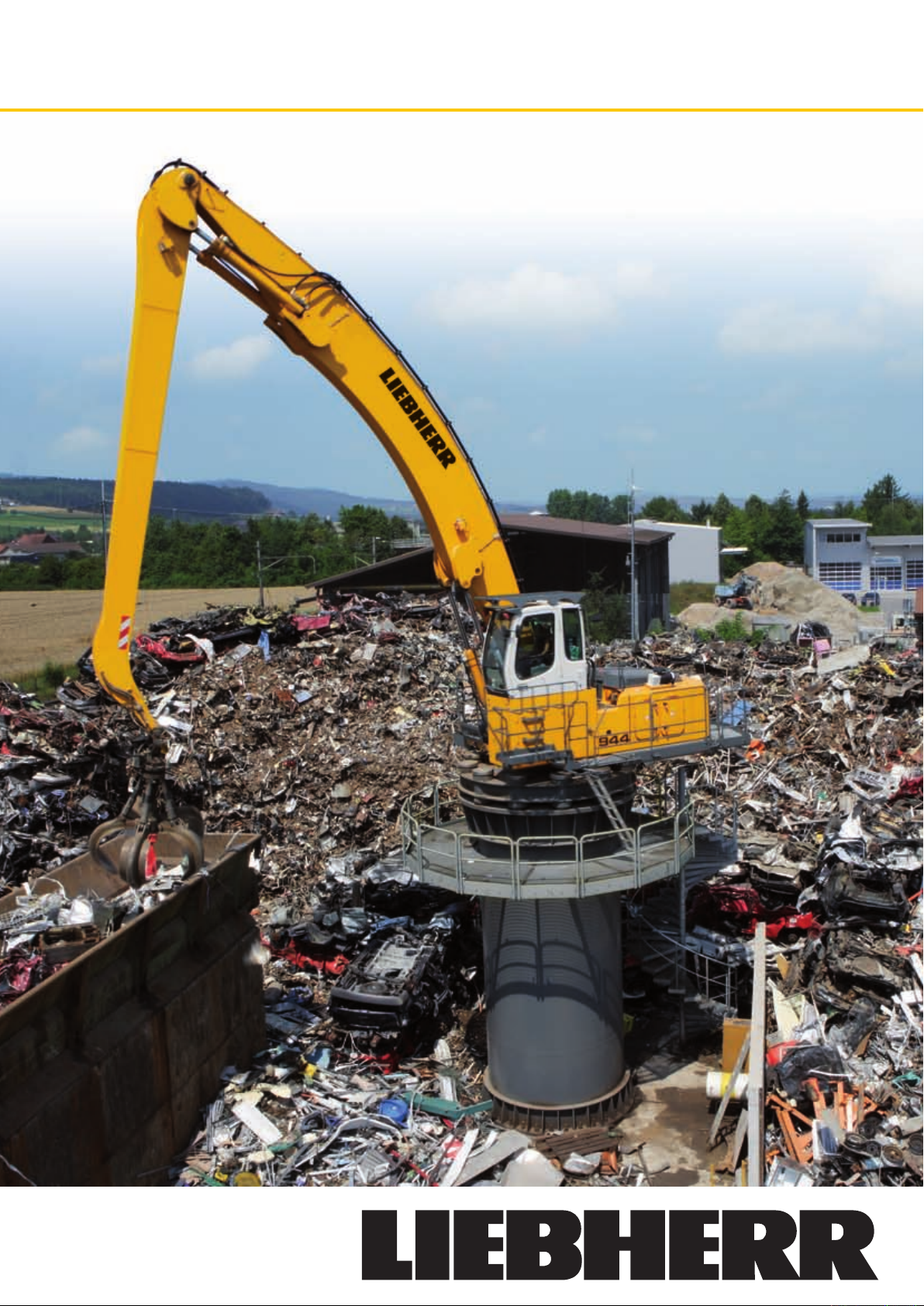
Stationary Electric Material Handlers
EP 934 C Working Radius: 13 - 20 m
EP 944 C Working Radius: 15 - 22 m
EP 954 C Working Radius: 16 - 24 m
Page 2
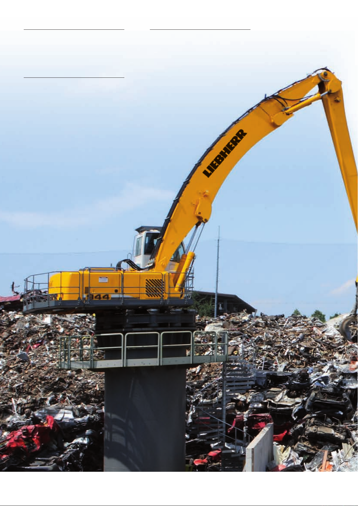
EP 934 C
EP 944 C
Working radius: 13 - 20 m
Motor rating: 160 kW/ 217 hp
Weight: 39,100 kg
EP 954 C
Working radius: 16 - 24 m
Motor rating: 250 kW/ 340 hp
Weight: 64,500 kg
Working radius: 15 - 22 m
Motor rating: 200 kW/ 272 hp
Weight: 51,900 kg
EP 934 C EP 944 C EP 954 C Material Handlers
2
Page 3
Performance
These new electric Material Handlers have been designed
to meet the specifi c needs of industrial handling. A wide
range of equipment and uppercarriages optimized for
long working radius provide the ideal answer to all the
demands which arise in the industry.
The performance of the kinematic chain formed from components from our in-house production, combined with the
power of the electric motor, maximize the performance of
the machine when it comes to lifting power, precision, and
speed of operation.
Reliability
Backed by more than 30 years experience in the construction of electric excavators, Liebherr designed the
new EP 934 C, EP 944 C and EP 954 C with the aim of
providing top performance whatever the challenge might
be. The structure of the machine, using components from
our own manufacture for the electric drive, has been completely rethought, and so moves away from simply being
an adaptation of a diesel-engine machine.
Being intended for key functions in the organization of industrial sites, Liebherr electric Material Handlers provide
a very high level of reliability. The service life of the hydraulic components has also been increased, thanks to
the smoother movement of the electric drive.
The concept of the single actuator (one single electric motor for all the hydraulic functions) allows for the risk area
associated with the low voltage at the electric cabinet to
be reduced even further.
Comfort
Helping the operator to concentrate on his work and get
the best out of his machine is achieved by providing a
comfortable driving position, good visibility, and a highly
ergonomic layout of the controls. The new electric Material Handlers offer the same level of comfort as on the
mobile excavators (arrangement of the controls, driver’s
seat, climate control, large window areas, etc.). The electric motor system adds a further layer of comfort thanks
to the low noise emissions and absence of vibration.
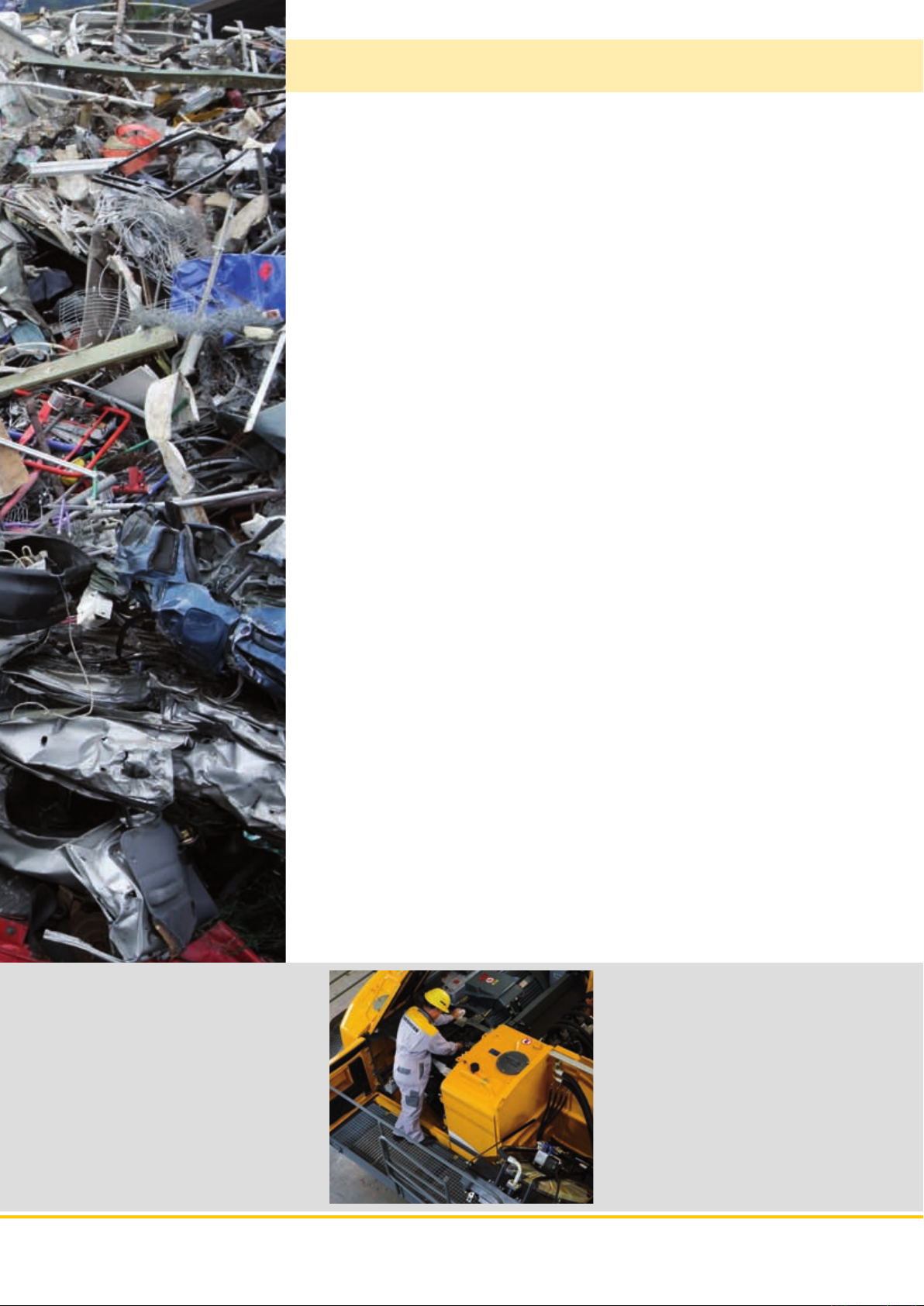
For Liebherr, comfort also means ease of daily maintenance of the machine in terms of access to the service
and inspection points, so as to minimize downtime.
Economy
Investing in the acquisition of an electric Material Handler is a great long-term advantage. Constant increases
in the costs of conventional energy sources are pushing
up operating charges, and reducing profi t margins considerably. Environmental criteria, in particular CO2 emissions, are also playing a constantly greater part in the
choice of power systems and working methods. With the
electric drive, Liebherr offers an economical alternative to
conventional diesel-engine machines, and a solution with
real respect for the environment.
EP 934 C EP 944 C EP 954 C Material Handlers
3
Page 4
EP 934 C EP 944 C EP 954 C Material Handlers
4
Ideal balance between power,
speed, and precision
• When it comes to handling metals,
timber, or any other application, a
wide choice of equipment in a broad
range of confi gurations means that
the most varied demands can always be met by specifi c solutions
• Optimization of the Material
Handlers goes well beyond just
the choice of equipment. It even
includes the adjustment of the hydraulics to meet the needs of the
site and of the operator
Page 5
Performance
These new electric Material Handlers have been designed to meet the specifi c
needs of industrial handling. A wide range of equipment and uppercarriages optimized for a long operating radius provide the ideal answer to all the demands
which arise in the industry.
The performance of the kinematic chain, formed from components from our own
in-house production, combined with the power of the electric motor, maximize
the performance of the Material handlers when it comes to lifting power, precision, and speed of operation.
Great lifting power
Excellent Working
Radius
Fast work cycles
Thanks to the optimised rear offset and the broach
kinematics of the equipment, the design concept
of the new uppercarriages means they can operate at exceptional outreach whilst guaranteeing a
good balance of forces and better absorption of
mechanical stresses.
Tough and designed for the most demanding of
applications, Liebherr equipment systems are
the perfect answer to every requirement when
it comes to lifting power and range of outreach.
Components are optimised by the fi nite element
calculation method.
The EP 934 C, EP 944 C and EP 954 C electric excavators are fi tted with the Liebherr Torque Control
system. The hydraulic guidance system on the excavator operates as a closed circuit, and does not
affect the speed of movement of the equipment
during the working cycle. The high torque and high
oil delivery from the guide pump maximize the excavator rotation speed.
A two-pump hydraulic system allows for operating
speeds to be reached which are unequalled anywhere. Regeneration on the circuits for the equipment allows for optimization of the hydraulic power
available and minimizing response time to the operator’s commands. This all results in a fl uidity of
movements which operators really appreciate.
Distributor
• Fine response of hydraulic control
for maximum working precision
• Immediate response to operator‘s
commands
• Three-pump hydraulic system, one of
which is a closed circuit dedicated to
the slewing of the Material Handlers
Precision of work
The fi ne response of the hydraulic control allows
for exceptional precision of work to be achieved
at long outreach, which contributes to the comfort
and convenience of the operator as well as achieving high performance results. Power is nothing
without control.
Tough structure
• High strength steel sheet at points subject to severe stress, stands up to the
most extreme demands
• Stable mounting of equipment elements
• Exceptional strength, even under intense
loading
EP 934 C EP 944 C EP 954 C Material Handlers
5
Page 6
EP 934 C EP 944 C EP 954 C Material Handlers
6
Reliability - Safety
• Automatic Power cut off if the
cabinet doors are opened
• Automatic power cut off in
the event of any anomalies
(electric motor or its bearings
overheating)
• Active safety on the transformers in the electric cabinet
Page 7
Reliability
Backed by more than 30 years experience in the construction of electrically powered excavators, Liebherr designed the new EP 934 C, EP 944 C and EP 954 C
with the aim of providing top performance whatever the challenge might be. The
structure of the excavator, using components from our own manufacture for the
electric drive, has been completely rethought, and so moves away from simply
being an adaptation of the diesel-engine excavator.
Being intended for key functions in the organization of industrial sites, Liebherr
electric Material Handlers provide a very high level of reliability. The service life
of the hydraulic components has also been increased thanks to the smoother
movement of the electric drive.
The concept of the single actuator (one single electric motor for all the hydraulic
functions) allows for the risk area associated with the low voltage at the electric
cabinet to be reduced even further.
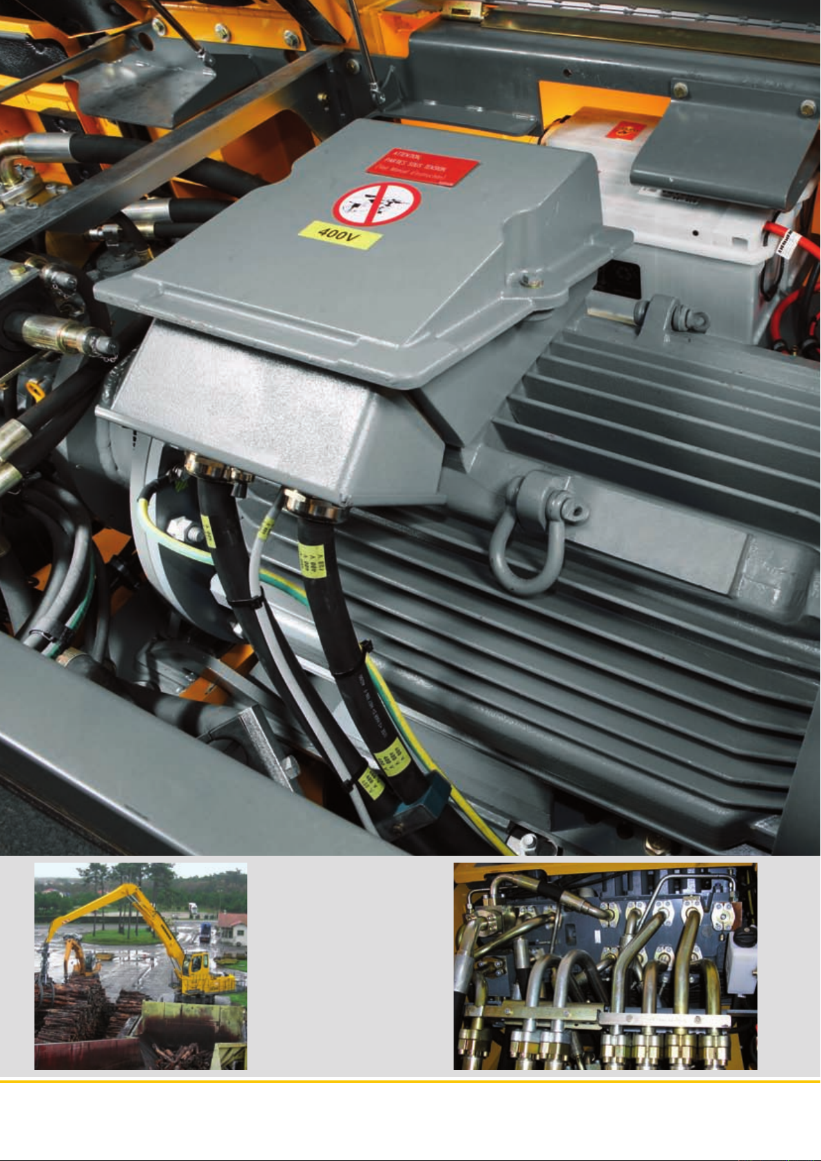
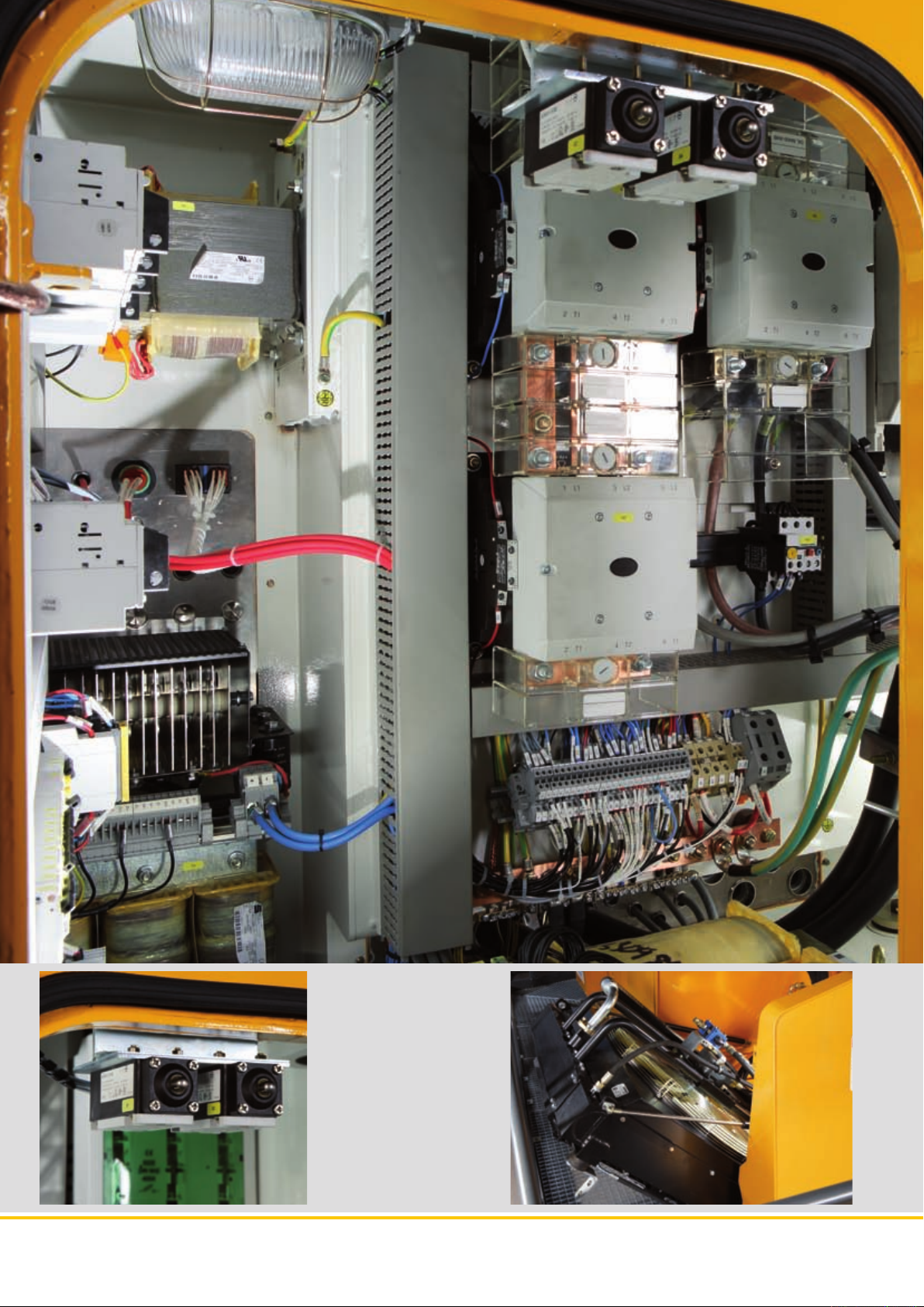
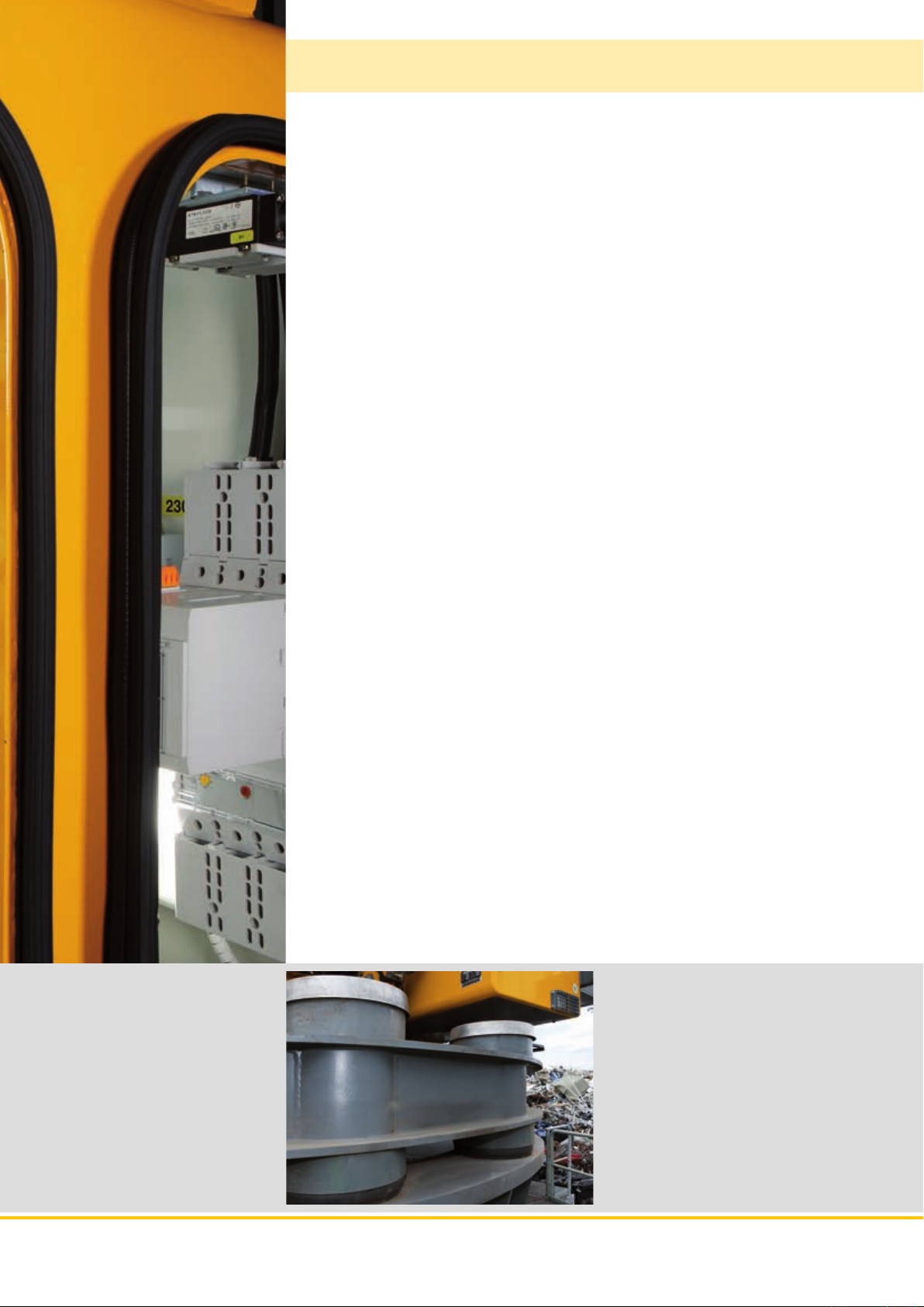
Electrical
system
Protected electric
cabinet
Electric motor
Totally integrated into the structure of the uppercarriages
and accommodated in a metal container, the electric cabinet provides a three-fold level of protection to the components of the electrical system:
- Mechanical (insulation from vibrations and from the possible impact of falling objects)
- Heat (maintains a constant temperature thanks to the
heating resistors which prevent corrosion from condensation)
- Electrical earthing of the structure and disconnection
from current is controlled from the cab by way of a motorised circuit-breaker.
The electric cabinet, like the rotating joint, provides IP55
class protection. A double fi ltration system (accessible
from the outside) places the cabinet under pressure,
which avoids any dust penetration and, with permanent
ventilation, ensures the thermal balance of all the components.
Liebherr electric excavators are equipped with motors
especially designed for really tough applications. The dimensions of the motor allow for the full power to be drawn
from the kinematic chain, and so maximises the performance of the machine. The motor can resist a momentary
overload of up to +25 % of its rated capacities.
Protected against penetration by water and dust, its properties correspond to protection class IP55.
The temperature of the roller bearings and other bearing
elements is constantly monitored, and, in the event of
overheating, the operator is warned of malfunction on the
console at the driving position.
Cooling system
• Generous dimensions for high
cooling capacity
• Vertical arrangement for increased effi ciency and minimal
incursion of foreign bodies
• Powered by a thermostatically
regulated hydraulic motor
• Hinged to allow for complete
cleaning
• Reversible actuation of the fan
(without time limit) as option
Elastic base
• Complete range of elastic bases especially
designed for each model
• Absorption of mechanical stresses (normally
transferred to the chassis of an excavator) if
mounted on a rigid structure (anchored metal
body, concrete body)
• Protection for the machine (in particular the
elements of the rotation assembly), as well as
for the load-bearing structure, against the axial
and radial forces generated by the operating
dynamics
EP 934 C EP 944 C EP 954 C Material Handlers
7
Page 8
EP 934 C EP 944 C EP 954 C Material Handlers
8
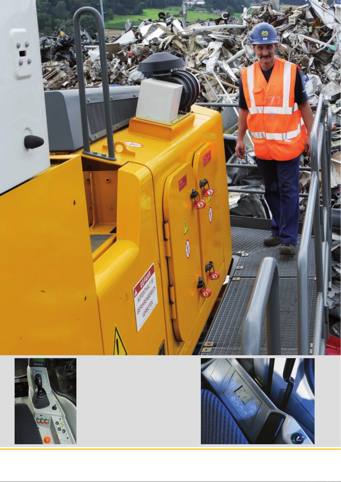
Cab with control panel
• The command arrangement for
putting the electrical system under
voltage is progressive (3 functions)
and the emergency stop button allows for the general cutting of the
electric cabinet supply
• Available as an option is a cut off
system deriving from one source
point, which can be activated from
the driving position via an additional rotating joint
Page 9
Comfort
Helping the operator to concentrate on his work and get the best out of his machine is achieved by a driving position which provides comfort, good visibility,
and a highly ergonomic layout of the controls. The new electric Material handlers
offer the same level of comfort as on the mobile excavators (arrangement of the
controls, driver’s seat, climate control, large window areas, etc.). The electric
motor system adds a further layer of comfort thanks to the low noise emissions
and absence of vibration.
For Liebherr, comfort also means ease of daily maintenance of the machine in terms
of access to the service and inspection points, so as to minimize downtime.
Driving position
Wide walkway with
safety rail
Low noise emissions
Carbon gas emission
Mounted as standard on a fi xed platform of 1 200 mm
(2 000 mm or hydraulic platform on request), the
new cab on the electric excavators meets all safety
standards in force (24 V supply in the operator's
compartment), comfort, panoramic visibility, and
ergonomic arrangement of the controls for perfect
control of the machine.
Arranged on the upperdeck, combines safety and
convenience for accessing all the maintenance
points on the machine. Access to the lower structure
(metallic base, concrete pedestal, chassis) can be
tailor-made depending on the type of installation.
Liebherr electric excavators are really quiet in operation. Their measured acoustic level is from 4 to 5 dB
lower than an equivalent diesel-engine version.
The level of noise intensity from a Liebherr electric
excavator represents less than a third of the noise
generated by a diesel-engine unit.
Zero grams of CO2 emitted per tonne of product
handled!
Climate control entirely automatic
• Automatic climate control ensures a
level of comfort similar to a private car
• Two sensors for precise temperature
regulation
• Ventilation fl aps can be adjusted
at the touch of a button
• Rapid demisting and defrosting
of the windscreen thanks to the
«reheat“ function
Easy maintenanc
• Optimum placement of components
on the uppercarriage
• Wide service walkway
• Easy access to service points thanks to
grouping together of inspection points
• Downtimes reduced to the minimum
EP 934 C EP 944 C EP 954 C Material Handlers
9
Page 10
EP 934 C EP 944 C EP 954 C Material Handlers
10
Wide range of solutions
• Modular arrangement for
rapid changeover
• Liebherr quick-coupling system,
mechanical and hydraulic, for effi cient
equipment changeover
• Quick-coupling arrangement for
hydraulic lines (Multi-Coupler)
• Complete range of grapples
• Range of different wood grapples
and grab buckets from Liebherr
Page 11

Economy
Investing in the acquisition of an electric excavator is a great long-term advantage. Constant increases in the costs of conventional energy sources are pushing up operating charges, and reducing profi t margins considerably. Environmental criteria, in particular CO
part in the choice of power systems and working methods. With the electric
drive, Liebherr offers an economical alternative to conventional diesel-engine
machines, and a solution with real respect for the environment.
emissions, are also playing a constantly greater
2
Flexibility and versatility
Energy costs cut
Increased service life
Maximum availability
Liebherr electric Material Handlers are multi-tasking machines. With a wide range of tools, which
can be combined with Liebherr quick-coupling
systems, they can create a degree of fl exibility and
versatility which has no comparison anywhere.
The energy yield from an electric motor is greater
than that of a diesel-engine. Delivering the same
kW output in hydraulic power costs three to fi ve
times less with an electric excavator than with a
diesel-engine unit. Liebherr excavators deliver the
full power from their kinematic chain and at a lot
less cost.
The smooth actuation of the electric drive and the
reliability of Liebherr hydraulic components mean
that the maintenance costs of the excavator can be
reduced considerably.
The absence of vibrations and variations in output
from a motor, which operates on a torque principle
and at constant output, means that the stress on
the kinematic chain can be reduced and the optional pre-heating of the hydraulic system allows
for the hydraulic oil to be kept at an optimum temperature right from the start.
The costs associated with maintenance operations are reduced to a minimum, and that also cuts
downtimes. The electric motor does not require any
maintenance beyond lubrication of the bearings
every 3,000 hours. No fi lters (air, oil) to be changed
and no draining of engine oil throughout the entire
service life of the machine.
Kinematic chain made by Liebherr
• Constant provision of power
for the kinematic chain
• Reduced wear of hydraulic
components
• Optimum exploitation of the hydraulic
power potential of the system
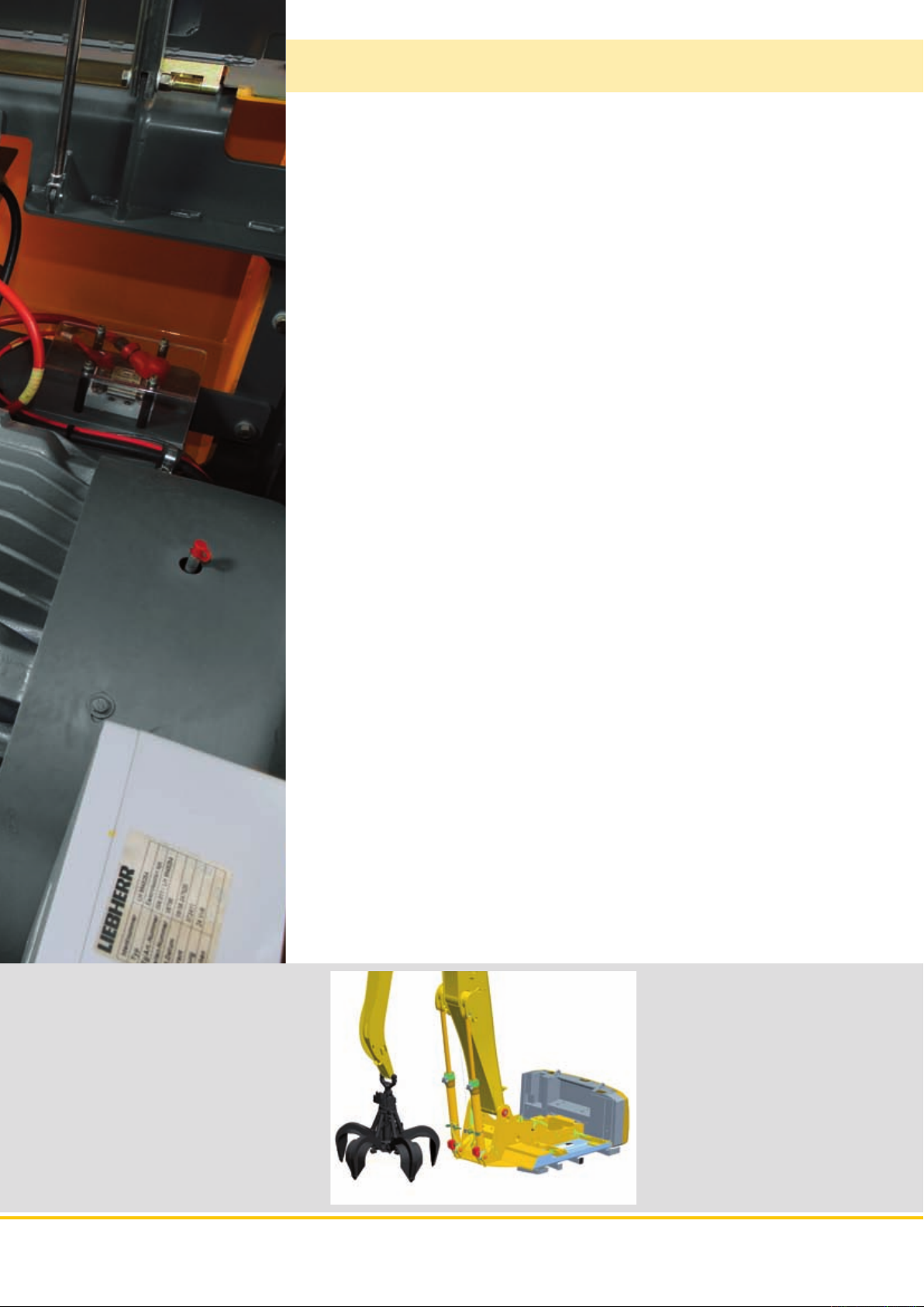
Battery
• Zero Grams emission of CO
• High yields
• Reduced costs
• Environmentally friendly
EP 934 C EP 944 C EP 954 C Material Handlers
2
11
Page 12

Technical Data
Electric Motor
�������������������������������
Motor
Power rating
EP 934 C
(as per CEI 34-1)
Rated voltage
Number of poles
Design type
Standard degree of protection
Insulation
Starter star/delta
Heat protection for windings
Heat protection for bearings
Anti-condensation heating system resistors
�����������������
���������������������
������������������
������������������������
���������������������������
asynchronous three-phase, cage rotor enclosed
in cast iron envelope, special Liebherr design
160 kW (217 HP) at 1,489 RPM
400 V – 50 Hz *
4
horizontal axle B35
axle height 315 mm
painting: RAL 7031
��
IP55 – steel flange FF600
class F, thermal loading: Class B,
ambient temperature 40 °C
Electric System
The 400 V electrical cabinet provides a degree of protection to IP55.
This houses the following components:
– Main motorised isolator, controlled from the cab
– Star/delta starter for motor
– Outlets for supplying auxiliary elements: heating, climate control
– Various heat protection devices
– Resistors for controlling the temperature of the cabinet
– Booster pump integrated in the cabinet: cabinet air filtered (option)
– Transformers – rectifier for 24 V control circuit
– Motor protection attachment
– Auxiliary batteries: 2 x 135 Ah/12 V: secured functions: lighting for excavator/
attachment position (option)
Hydraulic System
Hydraulic pumps
for the attachment
Max. flow
Max. pressure
Pump regulation
Hydraulic pump
for the swing drive
Max. flow
Max. pressure
Hydraulic tank
Hydraulic system
���������������������������
Filtration
�����������������������������
Cooling
Liebherr Tool Control
����������
���������������������
���������������
������������������
����������
���������������������
���������������
��������������������
�����������������
������������
two Liebherr swash plate pumps with variable
output
2 x 253 l/min.
350 bar
electro-hydraulic, with electronic regulation by
power limit, minimum pump flow at max. pres-
sure, distribution of oil to different receptor com-
ponents proportional to demand
reversible swash plate pump, in closed circuit
170 l/min.
370 bar
340 l
550 l
filter in the return circuit, with integrated fine filter
elements (5 µm)
radiator equipped with hydrostatic drive fan for
cooling the hydraulic oil and climate control
condenser
10 flow rates and pressures adjustable as option
for optional accessories
Swing Drive
����������������������������
Drive by
Transmission
Swing ring
Swing speed
Swing torque
Holding brake
Option
����������������������
�������������������������
����������������������
����������������������
���������������������
������������������������������
hydraulic swash plate motor with integrated
brake valves
Liebherr compact planetary reduction gear
Liebherr, sealed single race ball bearing swing
ring, internal teeth
0 – 9.4 RPM, stepless
81.07 kNm
oil-bath disk brake (negative action)
pedal controlled positioning brake
Operator’s Cab
���������������������������������
Cab
Operator’s seat
����������������������������
Controls
Monitoring
�������������������������
Climate control
�������������������
�������������������
single shell concept with shaped profiles, resil-
iently mounted, sound insulated, tinted windows.
Front window can be folded away under roof,
door with sliding window
shock absorbing suspension, adjustable to
operator’s weight, 6-way adjustable seat
integrated into adjustable seat consoles
menu driven digital display of current operating
conditions. Automatic monitoring, display, warn-
ing (audible and visual signal) and saving of
machine malfunction data, such as overheating
of windings, motor bearings, or low hydraulic oil
level
standard climate control system, combined
cooler/heater, additional dust filter in the outside/
fresh air circuit
Resilient Suspension
The resilient suspension consists of 12 resilient contact blocks. Its main function
is to absorb the shocks and vibrations resulting from the movement of the excavator.
An electrical rotating joint is integrated into the resilient suspension and allows
the electrical supply to the excavator to be assured. This meets the sealing
requirements of IP55.
Attachment
��������������������������������
Type
Hydraulic cylinders
�������������������������������
Pivots
Lubrication
VarioLift
������������������������
������������������������
Plus
���������������
high-strength steel for extreme stresses. Bearings
designed for optimum distribution of stresses
Liebherr cylinders with end-of-travel shock
absorbing, fitted with guide and sealing joints
Sealed, low maintenance
centralised semi-automatic Liebherr lubrication
system
variable boom mounting positions for optimized
lift capacities
Hydraulic Controls
Power distribution
Flow summation
Closed-loop circuit
Control
Attachment and swing
Travel
– speed pre-selection
Additional functions
* Other voltages and frequencies possible on request.
12 EP 934 C EP 944 C EP 954 C Machine for Industrial Applications
����������������
������������
���������
�����
�������������������������
��������������
with the aid of hydraulic distributors with inte-
grated safety valves
to boom stick and stick
for uppercarriage swing drive mechanism
proportional by handling element in cross opera-
tion
– proportional by pedals or by lever
proportional by pedals or by toggle switch
Page 13

The right attachment for every
application
Sorting grapple
Wood grapple
Straight boom 7.60 m
EP 934 C
Stick 5.00 m
Straight boom 8.60 m
Resilient suspension
Straight boom 9.60 m
Undercarriage
Stick 6.00 m
Straight boom 10.60 m
Multi-tine grapple
Clamshell bucket
Stick 7.50 m
Stick 8.00 m
Stick 9.00 m
Rigid cab elevation
Hydraulic Cab Elevation
Gooseneck boom 7.60 m
Hydraulic Cab Elevation
+ Intermediate Piece
Gooseneck boom 8.60 m
Gooseneck boom 9.60 m
EP 934 C EP 944 C EP 954 C Machine for Industrial Applications 13
Page 14

Industrial Attachment
with Industrial-Type Straight Boom 8.60 m
mft
55
16
50
14
45
EP 934 C
40
12
35
10
30
8
25
20
6
15
4
10
2
5
0
0
-5
-2
-10
-15
-20
-25
-4
-6
-8
1
2
Attachment Envelope
Kinematic variants 3A/3B
1 with industrial stick 6.00 m (3B)
2 with industrial stick 6.00 m and grapple model 65 (3B)
Operating Weight
Operating weight includes basic machine with rigid cab elevation
1.20 m, counterweight 7.5 t, handrails, industrial-type straight boom
8.60 m, industrial stick 6.00 m and grapple model 70 C with 5 semiclosed tines 0.60 m
Weight 38,100 kg
3
.
40 3035455055 2025 1015
4 2 06810121416
m
05 ft
14 EP 934 C EP 944 C EP 954 C Machine for Industrial Applications
Page 15

Lift Capacities
with Industrial-Type Straight Boom 8.60 m
Industrial Stick 6.00 m (Variant 3B)
3.0 m 4.5 m 6.0 m 7.5 m 9.0 m 10.5 m 12.0 m 13.5 m 15.0 m 16.5 m 18.0 m 19.5 m 21.0 m
Under m carriage m
Ponton
21.0
Ponton
19.5
Ponton
18.0
Ponton
16.5
15.0
13.5
12.0
10.5
9.0
7.5
6.0
4.5
3.0
1.5
0
– 1.5
– 3.0
– 4.5
– 6.0
– 7.5
– 9.0
– 10.5
Ponton
Ponton
Ponton
Ponton
Ponton
Ponton
Ponton
Ponton
Ponton
Ponton
Ponton
Ponton
Ponton
Ponton
Ponton
Ponton
Ponton
Ponton
9.9* 9.9* 8.0* 8.0*
8.9* 8.9* 8.0* 8.0* 6.3* 6.3*
7.5* 7.5* 7.1* 7.1* 5.6* 5.6*
7.4* 7.4* 6.9* 6.9* 6.5* 6.5* 5.2* 5.2*
7.5* 7.5* 6.9* 6.9* 6.4* 6.4* 6.1* 6.1* 5.0* 5.0*
8.8* 8.8* 7.8* 7.8* 7.1* 7.1* 6.5* 6.5* 6.1* 6.1* 4.8* 4.8*
11.7* 11.7* 9.7* 9.7* 8.3* 8.3* 7.4* 7.4* 6.7* 6.7* 6.2* 6.2* 5.7* 5.7* 4.8* 4.8*
17.6* 17.6* 14.0* 14.0* 10.9* 10.9* 9.0* 9.0* 7.8* 7.8* 7.0* 7.0* 6.3* 6.3* 5.7* 5.7* 4.8* 4.8*
16.6* 16.6* 12.2* 12.2* 9.8* 9.8* 8.3* 8.3* 7.2* 7.2* 6.4* 6.4* 5.8* 5.8* 4.9* 4.9*
5.5* 5.5* 13.3* 13.3* 10.4* 10.4* 8.7* 8.7* 7.5* 7.5* 6.5* 6.5* 5.8* 5.8* 5.1* 5.1*
4.5* 4.5* 13.6* 13.6* 10.8* 10.8* 8.9* 8.9* 7.6* 7.6* 6.6* 6.6* 5.7* 5.7* 5.2* 5.2*
5.2* 5.2* 11.2* 11.2* 10.9* 10.9* 9.0* 9.0* 7.6* 7.6* 6.5* 6.5* 5.5* 5.5* 5.3* 5.3*
11.3* 11.3* 10.6* 10.6* 8.7* 8.7* 7.3* 7.3* 6.1* 6.1* 6.0* 6.0*
5.70
8.41
10.20
11.51
12.51
13.26
13.81
14.17
14.36
14.40
14.27
13.75
12.25
EP 934 C
Height Can be slewed through 360° In longitudinal position of undercarriage Max. reach * Limited by hydr. capacity
The lift capacities are stated in metric tonnes (t) on the lifting gear’s stick tip, and can be lifted 360° on firm, level supporting surface. Capacities
are valid for 600 mm wide triple grouser pads. Indicated loads are based on ISO 10567 standard and do not exceed 75 % of tipping or 87 % of
hydraulic capacity (indicated via *). Lifting capacity of the excavator is limited by machine stability, hydraulic capacity and maximum permissible
load of the load hook.
According to European Standard, EN 474-5: In the European Union excavators have to be equipped with an overload warning device, a load
diagram and automatic check valves on the hoist cylinders, when they are used for lifting operations which require the use of lifting accessories.
EP 934 C EP 944 C EP 954 C Machine for Industrial Applications 15
Page 16

Industrial Attachment
with Industrial-Type Gooseneck Boom 9.60 m
mft
18
55
16
50
EP 934 C
14
45
40
12
35
10
30
8
25
20
6
15
4
10
2
5
0
0
-5
-2
-10
-4
-15
-6
-20
-25
-30
-35
-8
-8
-10
1
2
4 2 068101214161820
m
Attachment Envelope
Kinematic variants 3C/3D
1 with industrial stick 9.00 m (3D)
2 with industrial stick 9,00 m and grapple model 65 (3D)
Operating Weight
Operating weight includes basic machine with rigid cab elevation
1.20 m, counterweight 7.5 t, handrails, industrial-type gooseneck
boom 9.60 m, industrial stick 9.00 m and grapple model 65 with
5 semi-closed tines 0.60 m
Weight 39,100 kg
3
.
40 30354550556065 2025 1015
05 ft
16 EP 934 C EP 944 C EP 954 C Machine for Industrial Applications
Page 17

Lift Capacities
with Industrial-Type Gooseneck Boom 9.60 m
Industrial Stick 9.00 m (Variant 3D)
3.0 m 4.5 m 6.0 m 7.5 m 9.0 m 10.5 m 12.0 m 13.5 m 15.0 m 16.5 m 18.0 m 19.5 m 21.0 m
Under m carriage m
Ponton
21.0
Ponton
19.5
Ponton
18.0
16.5
15.0
13.5
12.0
10.5
9.0
7.5
6.0
4.5
3.0
1.5
0
– 1.5
– 3.0
– 4.5
– 6.0
– 7.5
– 9.0
– 10.5
Ponton
Ponton
Ponton
Ponton
Ponton
Ponton
Ponton
Ponton
Ponton
Ponton
Ponton
Ponton
Ponton
Ponton
Ponton
Ponton
Ponton
Ponton
Ponton
3.8* 3.8*
4.6* 4.6* 3.4* 3.4*
4.3* 4.3* 3.2* 3.2*
4.2* 4.2* 4.1* 4.1* 3.0* 3.0*
4.2* 4.2* 4.0* 4.0* 3.6* 3.6* 2.9* 2.9*
4.2* 4.2* 4.0* 4.0* 3.9* 3.9* 2.9* 2.9*
4.6* 4.6* 4.3* 4.3* 4.1* 4.1* 3.9* 3.9* 3.4* 3.4* 2.9* 2.9*
4.8* 4.8* 4.5* 4.5* 4.2* 4.2* 4.0* 4.0* 3.8* 3.8* 2.9* 2.9*
5.7* 5.7* 5.2* 5.2* 4.7* 4.7* 4.4* 4.4* 4.1* 4.1* 3.8* 3.8* 2.9* 2.9*
8.7* 8.7* 7.2* 7.2* 6.2* 6.2* 5.5* 5.5* 5.0* 5.0* 4.5* 4.5* 4.2* 4.2* 3.9* 3.9* 3.0* 3.0*
8.3* 8.3* 13.7* 13.7* 10.1* 10.1* 8.1* 8.1* 6.8* 6.8* 5.9* 5.9* 5.2* 5.2* 4.7* 4.7* 4.3* 4.3* 4.0* 4.0* 3.1* 3.1*
3.2* 3.2* 9.0* 9.0* 11.2* 11.2* 8.8* 8.8* 7.3* 7.3* 6.2* 6.2* 5.4* 5.4* 4.9* 4.9* 4.4* 4.4* 4.0* 4.0* 3.3* 3.3*
3.1* 3.1* 6.0* 6.0* 12.0* 12.0* 9.3* 9.3* 7.6* 7.6* 6.5* 6.5* 5.6* 5.6* 5.0* 5.0* 4.5* 4.5* 4.0* 4.0* 3.4* 3.4*
3.5* 3.5* 5.5* 5.5* 9.9* 9.9* 9.7* 9.7* 7.9* 7.9* 6.6* 6.6* 5.7* 5.7* 5.0* 5.0* 4.5* 4.5* 3.9* 3.9* 3.7* 3.7*
4.0* 4.0* 5.7* 5.7* 9.0* 9.0* 9.7* 9.7* 8.0* 8.0* 6.7* 6.7* 5.8* 5.8* 5.0* 5.0* 4.4* 4.4* 3.7* 3.7* 3.7* 3.7*
6.0* 6.0* 8.8* 8.8* 9.5* 9.5* 7.8* 7.8* 6.6* 6.6* 5.6* 5.6* 4.9* 4.9* 4.1* 4.1* 3.7* 3.7*
9.1* 9.1* 9.0* 9.0* 7.4* 7.4* 6.3* 6.3* 5.3* 5.3* 4.5* 4.5* 4.4* 4.4*
9.96
11.90
13.39
14.57
15.51
16.26
16.84
17.27
17.56
17.72
17.75
17.65
17.42
17.05
16.54
15.87
13.69
EP 934 C
Height Can be slewed through 360° In longitudinal position of undercarriage Max. reach * Limited by hydr. capacity
The lift capacities are stated in metric tonnes (t) on the lifting gear’s stick tip, and can be lifted 360° on firm, level supporting surface. Capacities
are valid for 600 mm wide triple grouser pads. Indicated loads are based on ISO 10567 standard and do not exceed 75 % of tipping or 87 % of
hydraulic capacity (indicated via *). Lifting capacity of the excavator is limited by machine stability, hydraulic capacity and maximum permissible
load of the load hook.
According to European Standard, EN 474-5: In the European Union excavators have to be equipped with an overload warning device, a load
diagram and automatic check valves on the hoist cylinders, when they are used for lifting operations which require the use of lifting accessories.
EP 934 C EP 944 C EP 954 C Machine for Industrial Applications 17
Page 18

Technical Data
Electric Motor
�������������������������������
Motor
Power rating
(as per CEI 34-1)
Rated voltage
Number of poles
Form of construction
Standard degree of protection
Insulation
EP 944 C
Starter star/delta
Heat protection for windings
Heat protection for bearings
Anti-condensation heating system resistors
�����������������
���������������������
������������������
������������
���������������������������
asynchronous three-phase. cage rotor enclosed
in cast iron envelope. special Liebherr design
200 kW (272 HP) at 1,485 RPM
400 V – 50 Hz *
4
horizontal axis B35
axle height 315 mm
painting: RAL 7031
��
IP55 – steel flange FF600
class F, thermal loading: Class B,
ambient temperature 40 °C
Electric System
The 400 V electrical cabinet provides a degree of protection to IP55.
This houses the following components:
– Main motorised isolator, controlled from the cab
– Star/delta starter for motor
– Outlets for supplying auxiliary elements: heating, climate control
– Various heat protection devices
– Resistors for controlling the temperature of the cabinet
– Booster pump integrated in the cabinet: cabinet air filtered (option)
– Transformers – rectifier for 24 V control circuit
– Motor protection attachment
– Auxiliary batteries: 2 x 135 Ah/12 V: secured functions: lighting for excavator/
attachment position (option)
Hydraulic System
Hydraulic pumps
for the attachment
Max. flow
Max. pressure
Pump regulation
Hydraulic pump
for the swing drive
Max. flow
Max. pressure
Hydraulic tank
Hydraulic system
���������������������������
Filtration
�����������������������������
Cooling
Liebherr Tool Control
����������
���������������������
���������������
������������������
����������
���������������������
���������������
��������������������
�����������������
������������
two Liebherr swash plate pumps with variable
output
2 x 305 l/min.
350 bar
electro-hydraulic, with electronic regulation by
power limit, minimum pump flow at max. pres-
sure, distribution of oil to different receptor com-
ponents proportional to demand
reversible swash plate pump, in closed circuit
205 l/min.
370 bar
460 l
710 l
2 filters in the return circuit, with integrated fine
filter elements (5 µm)
radiator equipped with hydrostatic drive fan for
cooling the hydraulic oil and climate control
condenser
10 flow rates and pressures adjustable as option
for optional accessories
Swing Drive
����������������������������
Drive by
Transmission
Swing ring
Swing speed
Swing torque
Holding brake
Option
����������������������
�������������������������
����������������������
����������������������
���������������������
������������������������������
hydraulic swash plate motor with integrated
brake valves
Liebherr compact planetary reduction gear
Liebherr, sealed single race ball bearing swing
ring, internal teeth
0 – 7.9 RPM, stepless
119 kNm
oil-bath disk brake (negative action)
pedal controlled positioning brake
Operator’s Cab
���������������������������������
Cab
Operator’s seat
����������������������������
Controls
Monitoring
�������������������������
Climate control
�������������������
�������������������
single shell concept with shaped profiles, resil-
iently mounted, sound insulated,tinted windows,
Front window can be folded away under roof,
door with sliding window
shock absorbing suspension. adjustable to
operator’s weight. 6-way adjustable seat
integrated into adjustable seat consoles
menu driven digital display of current operating
conditions. Automatic monitoring, display, warn-
ing (audible and visual signal) and saving of
machine malfunction data, such as overheating
of windings, motor bearings, or low hydraulic oil
level
standard climate control system. combined
cooler/heater, additional dust filter in the outside/
fresh air circuit
Resilient Suspension
The resilient suspension consists of 12 resilient contact blocks. Its main function
is to absorb the shocks and vibrations resulting from the movement of the excavator.
An electrical rotating joint is integrated into the resilient suspension and allows
the electrical supply to the excavator to be assured. This meets the sealing
requirements of IP55.
Attachment
��������������������������������
Type
Hydraulic cylinders
�������������������������������
Pivots
Lubrication
VarioLift
������������������������
������������������������
Plus
���������������
high-strength steel for extreme stresses. Bearings
designed for optimum distribution of stresses.
Liebherr cylinders with end-of-travel shock
absorbing, fitted with guide and sealing joints
sealed, low maintenance
centralised semi-automatic Liebherr lubrication
system
variable boom mounting positions for optimized
lift capacities
Hydraulic Controls
Power distribution
Flow summation
Closed-loop circuit
Control
Attachment and swing
Travel
– speed pre-selection
Additional functions
* Other voltages and frequencies possible on request.
18 EP 934 C EP 944 C EP 954 C Machine for Industrial Applications
����������������
������������
���������
�����
�������������������������
��������������
with the aid of hydraulic distributors with inte-
grated safety valves
to boom stick and stick
for uppercarriage swing drive mechanism
proportional by handling element in cross opera-
tion
– proportional by pedals or by lever
proportional by pedals or by toggle switch
Page 19

The right attachment for every
application
Straight boom 8.50 m
Sorting
grapple
Wood
grapple
Multi-tine
grapple
Stick 6.00 m
Stick 5.80 m
Stick 7.30 m
Stick 8.80 m
EP 944 C
Straight boom 9.50 m
Resilient suspension
Straight boom 10.50 m
Undercarriage
Straight boom 11.50 m
Rigid cab elevation
Clamshell
bucket
Stick 9.50 m
Stick 12.00 m
Gooseneck boom 7.50 m
Gooseneck boom 9.50 m
Gooseneck boom 11.50 m
Hydraulic Cab Elevation
Hydraulic Cab Elevation
+ Intermediate Piece
EP 934 C EP 944 C EP 954 C Machine for Industrial Applications 19
Page 20

Industrial Attachment
with Industrial-Type Straight Boom 9.50 m
mft
60
18
55
16
50
14
45
40
12
35
10
30
EP 944 C
25
20
15
10
-10
-15
-20
-25
-30
8
6
4
2
5
0
0
-5
-2
-4
-6
-8
-10
1
2
4 2 0681012141618
m
Attachment Envelope
Kinematic variants 3A/3B
1 with industrial stick 7.30 m (3B)
2 with industrial stick 7.30 m and grapple model 70 C (3B)
Operating Weight
Operating weight includes basic machine with rigid cab elevation
1.20 m, counterweight 11.0 t, handrails, industrial-type straight boom
9.50 m, industrial stick 7.30 m and grapple model 70 C with 5 semiclosed tines 1.10 m
Weight 49,600 kg
3
.
40 303545505560 2025 1015
05 ft
20 EP 934 C EP 944 C EP 954 C Machine for Industrial Applications
Page 21

Lift Capacities
with Industrial-Type Straight Boom 9.50 m
Industrial Stick 7.30 m (Variant 3B)
3.0 m 4.5 m 6.0 m 7.5 m 9.0 m 10.5 m 12.0 m 13.5 m 15.0 m 16.5 m 18.0 m 19.5 m 21.0 m
Under m carriage m
Ponton
21.0
Ponton
19.5
Ponton
18.0
16.5
15.0
13.5
12.0
10.5
9.0
7.5
6.0
4.5
3.0
1.5
0
– 1.5
– 3.0
– 4.5
– 6.0
– 7.5
– 9.0
– 10.5
Ponton
Ponton
Ponton
Ponton
Ponton
Ponton
Ponton
Ponton
Ponton
Ponton
Ponton
Ponton
Ponton
Ponton
Ponton
Ponton
Ponton
Ponton
Ponton
12.3* 12.3* 10.1* 10.1* 9.4* 9.4*
10.9* 10.9* 10.1* 10.1* 8.0* 8.0*
10.3* 10.3* 9.5* 9.5* 9.0* 9.0* 7.3* 7.3*
9.3* 9.3* 8.8* 8.8* 8.4* 8.4* 6.8* 6.8*
10.1* 10.1* 9.4* 9.4* 8.8* 8.8* 8.3* 8.3* 7.9* 7.9* 6.6* 6.6*
10.5* 10.5* 9.6* 9.6* 8.9* 8.9* 8.3* 8.3* 7.9* 7.9* 6.4* 6.4*
11.1* 11.1* 10.0* 10.0* 9.2* 9.2* 8.5* 8.5* 8.0* 8.0* 7.5* 7.5* 6.3* 6.3*
14.1* 14.1* 12.1* 12.1* 10.7* 10.7* 9.6* 9.6* 8.8* 8.8* 8.1* 8.1* 7.6* 7.6* 6.3* 6.3*
20.7* 20.7* 16.0* 16.0* 13.2* 13.2* 11.4* 11.4* 10.1* 10.1* 9.1* 9.1* 8.3* 8.3* 7.6* 7.6* 6.4* 6.4*
24.8* 24.8* 18.1* 18.1* 14.5* 14.5* 12.2* 12.2* 10.6* 10.6* 9.4* 9.4* 8.5* 8.5* 7.7* 7.7* 6.5* 6.5*
6.9* 6.9* 19.9* 19.9* 15.5* 15.5* 12.8* 12.8* 11.0* 11.0* 9.7* 9.7* 8.6* 8.6* 7.8* 7.8* 6.7* 6.7*
5.6* 5.6* 15.5* 15.5* 16.3* 16.3* 13.3* 13.3* 11.3* 11.3* 9.9* 9.9* 8.7* 8.7* 7.7* 7.7* 6.8* 6.8*
6.3* 6.3* 12.9* 12.9* 16.5* 16.5* 13.6* 13.6* 11.5* 11.5* 9.9* 9.9* 8.7* 8.7* 7.5* 7.5* 6.6* 6.6*
13.0* 13.0* 16.3* 16.3* 13.4* 13.4* 11.4* 11.4* 9.7* 9.7* 8.4* 8.4* 7.2* 7.2*
15.5* 15.5* 12.9* 12.9* 10.9* 10.9* 9.3* 9.3* 8.6* 8.6*
7.85
10.17
11.85
13.15
14.16
14.95
15.56
16.00
16.29
16.44
16.44
16.31
16.03
14.88
12.67
EP 944 C
Height Can be slewed through 360° In longitudinal position of undercarriage Max. reach * Limited by hydr. capacity
The lift capacities are stated in metric tonnes (t) on the lifting gear’s stick tip, and can be lifted 360° on firm, level supporting surface. Capacities
are valid for 600 mm wide triple grouser pads. Indicated loads are based on ISO 10567 standard and do not exceed 75 % of tipping or 87 % of
hydraulic capacity (indicated via *). Lifting capacity of the excavator is limited by machine stability, hydraulic capacity and maximum permissible
load of the load hook.
According to European Standard, EN 474-5: In the European Union excavators have to be equipped with an overload warning device, a load
diagram and automatic check valves on the hoist cylinders, when they are used for lifting operations which require the use of lifting accessories.
EP 934 C EP 944 C EP 954 C Machine for Industrial Applications 21
Page 22

Industrial Attachment
with Industrial-Type Gooseneck Boom 11.50 m
mft
20
65
60
18
55
16
50
14
45
40
12
35
10
30
EP 944 C
25
20
15
10
-10
-15
-20
-25
-30
-35
-40
8
6
4
2
5
0
0
-5
-2
-4
-6
-8
-10
-12
1
2
4 2 06810121416182022
m
Attachment Envelope
Kinematic variants 3C/3D
1 with industrial stick 12.00 m (3D)
2 with industrial stick 12.00 m and grapple model 70 C (3D)
Operating Weight
Operating weight includes basic machine with rigid cab elevation
1.20 m, counterweight 11.0 t, handrails, industrial-type gooseneck
boom 12.00 m, industrial stick 12.00 m and grapple model 70 C with
5 semi-closed tines 1.10 m
Weight 51,900 kg
3
.
40 3035455055606570 2025 1015
05 ft
22 EP 934 C EP 944 C EP 954 C Machine for Industrial Applications
Page 23

Lift Capacities
with Industrial-Type Gooseneck Boom 11.50 m
Industrial Stick 12.00 m (Variant 3D)
3.0 m 4.5 m 6.0 m 7.5 m 9.0 m 10.5 m 12.0 m 13.5 m 15.0 m 16.5 m 18.0 m 19.5 m 21.0 m
Under m carriage m
21.0
19.5
18.0
16.5
15.0
13.5
12.0
10.5
9.0
7.5
6.0
4.5
3.0
1.5
0
– 1.5
– 3.0
– 4.5
– 6.0
– 7.5
– 9.0
– 10.5
Ponton
Ponton
Ponton
Ponton
Ponton
Ponton
Ponton
Ponton
Ponton
Ponton
Ponton
Ponton
Ponton
Ponton
Ponton
Ponton
Ponton
Ponton
Ponton
Ponton
Ponton
Ponton
4.3* 4.3*
4.0* 4.0* 3.9* 3.9*
4.6* 4.6* 4.0* 4.0* 3.6* 3.6*
4.2* 4.2* 3.7* 3.7* 3.4* 3.4*
4.1* 4.1* 4.0* 4.0* 3.3* 3.3* 3.2* 3.2*
4.1* 4.1* 4.0* 4.0* 3.8* 3.8* 3.1* 3.1*
4.1* 4.1* 3.9* 3.9* 3.8* 3.8* 3.5* 3.5* 3.1* 3.1*
4.2* 4.2* 4.0* 4.0* 3.8* 3.8* 3.7* 3.7* 3.1* 3.1*
4.5* 4.5* 4.3* 4.3* 4.0* 4.0* 3.9* 3.9* 3.7* 3.7* 3.2* 3.2* 3.1* 3.1*
4.7* 4.7* 4.4* 4.4* 4.1* 4.1* 3.9* 3.9* 3.7* 3.7* 3.6* 3.6* 3.1* 3.1*
5.3* 5.3* 4.9* 4.9* 4.6* 4.6* 4.3* 4.3* 4.0* 4.0* 3.8* 3.8* 3.6* 3.6* 3.1* 3.1*
6.2* 6.2* 5.6* 5.6* 5.1* 5.1* 4.7* 4.7* 4.4* 4.4* 4.1* 4.1* 3.9* 3.9* 3.6* 3.6* 3.2* 3.2*
7.6* 7.6* 6.7* 6.7* 6.0* 6.0* 5.4* 5.4* 4.9* 4.9* 4.6* 4.6* 4.2* 4.2* 3.9* 3.9* 3.7* 3.7* 3.3* 3.3*
16.9* 16.9* 12.6* 12.6* 10.1* 10.1* 8.4* 8.4* 7.2* 7.2* 6.4* 6.4* 5.7* 5.7* 5.1* 5.1* 4.7* 4.7* 4.3* 4.3* 4.0* 4.0* 3.7* 3.7* 3.4* 3.4*
16.7* 16.7* 14.3* 14.3* 11.1* 11.1* 9.1* 9.1* 7.7* 7.7* 6.7* 6.7* 6.0* 6.0* 5.4* 5.4* 4.9* 4.9* 4.4* 4.4* 4.1* 4.1* 3.8* 3.8* 3.5* 3.5*
7.6* 7.6* 15.6* 15.6* 12.0* 12.0* 9.7* 9.7* 8.2* 8.2* 7.1* 7.1* 6.2* 6.2* 5.5* 5.5* 5.0* 5.0* 4.5* 4.5* 4.2* 4.2* 3.8* 3.8* 3.6* 3.6*
6.2* 6.2* 11.1* 11.1* 12.7* 12.7* 10.2* 10.2* 8.5* 8.5* 7.3* 7.3* 6.4* 6.4* 5.7* 5.7* 5.1* 5.1* 4.6* 4.6* 4.2* 4.2* 3.8* 3.8* 3.6* 3.6*
6.0* 6.0* 9.4* 9.4* 13.1* 13.1* 10.6* 10.6* 8.8* 8.8* 7.5* 7.5* 6.6* 6.6* 5.8* 5.8* 5.2* 5.2* 4.6* 4.6* 4.2* 4.2* 3.7* 3.7* 3.7* 3.7*
6.2* 6.2* 8.9* 8.9* 13.2* 13.2* 10.7* 10.7* 8.9* 8.9* 7.6* 7.6* 6.6* 6.6* 5.8* 5.8* 5.2* 5.2* 4.6* 4.6* 4.1* 4.1* 3.7* 3.7*
6.5* 6.5* 8.9* 8.9* 13.0* 13.0* 10.7* 10.7* 8.9* 8.9* 7.6* 7.6* 6.6* 6.6* 5.8* 5.8* 5.1* 5.1* 4.5* 4.5* 3.9* 3.9* 3.7* 3.7*
6.9* 6.9* 9.1* 9.1* 12.7* 12.7* 10.4* 10.4* 8.8* 8.8* 7.5* 7.5* 6.5* 6.5* 5.6* 5.6* 4.9* 4.9* 4.3* 4.3* 3.9* 3.9*
12.0* 12.0* 9.9* 9.9* 8.4* 8.4* 7.2* 7.2* 6.2* 6.2* 5.3* 5.3* 4.7* 4.7*
11.50
13.69
15.43
16.85
18.03
19.02
19.85
20.53
21.08
21.51
21.83
22.05
22.15
22.16
22.06
21.86
21.55
21.13
20.59
19.92
18.86
16.24
EP 944 C
Height Can be slewed through 360° In longitudinal position of undercarriage Max. reach * Limited by hydr. capacity
The lift capacities are stated in metric tonnes (t) on the lifting gear’s stick tip, and can be lifted 360° on firm, level supporting surface. Capacities
are valid for 600 mm wide triple grouser pads. Indicated loads are based on ISO 10567 standard and do not exceed 75 % of tipping or 87 % of
hydraulic capacity (indicated via *). Lifting capacity of the excavator is limited by machine stability, hydraulic capacity and maximum permissible
load of the load hook.
According to European Standard, EN 474-5: In the European Union excavators have to be equipped with an overload warning device, a load
diagram and automatic check valves on the hoist cylinders, when they are used for lifting operations which require the use of lifting accessories.
EP 934 C EP 944 C EP 954 C Machine for Industrial Applications 23
Page 24

Technical Data
Electric Motor
�������������������������������
Motor
Power rating
(as per CEI 34-1)
Rated voltage
Number of poles
Design type
Standard degree of protection
Insulation
Starter star/delta
Heat protection for windings
Heat protection for bearings
Anti-condensation heating system resistors
EP 954 C
The 400 V electrical cabinet provides a degree of protection to IP55.
This houses the following components:
– Main motorised isolator, controlled from the cab
– Star/delta starter for motor
– Outlets for supplying auxiliary elements: heating, climate control
– Various heat protection devices
– Resistors for controlling the temperature of the cabinet
– Booster pump integrated in the cabinet: cabinet air filtered (option)
– Transformers – rectifier for 24 V control circuit
– Motor protection attachment
– Auxiliary batteries: 2 x 135 Ah/12 V: secured functions: lighting for excavator/
attachment position (option)
�����������������
���������������������
������������������
������������������������
���������������������������
Electric System
asynchronous three-phase, cage rotor enclosed
in cast iron envelope, special Liebherr design
250 kW (340 HP) at 1,489 RPM
400 V – 50 Hz *
4
horizontal axle B35
axle height 315 mm
painting: RAL 7031
��
IP55 – steel flange FF600
class F, thermal loading: Class B,
ambient temperature 40 °C
Hydraulic System
Hydraulic pumps
for the attachment
Max. flow
Max. pressure
Pump regulation
Hydraulic pump
for the swing drive
Max. flow
Max. pressure
Hydraulic tank
Hydraulic system
���������������������������
Filtration
�����������������������������
Cooling
Liebherr Tool Control
����������
���������������������
���������������
������������������
����������
���������������������
���������������
��������������������
�����������������
������������
two Liebherr swash plate pumps with variable
output
2 x 341 l/min.
370 bar
electro-hydraulic, with electronic regulation by
power limit, minimum pump flow at max. pres-
sure, distribution of oil to different receptor com-
ponents proportional to demand
reversible swash plate pump, in closed circuit
205 l/min.
370 bar
440 l
790 l
2 filters in the return circuit, with integrated fine
filter elements (5 µm)
radiator equipped with hydrostatic drive fan for
cooling the hydraulic oil and climate control
condenser
10 flow rates and pressures adjustable as option
for optional accessories
Swing Drive
����������������������������
Drive by
Transmission
Swing ring
Swing speed
Swing torque
Holding brake
Option
����������������������
�������������������������
����������������������
����������������������
���������������������
������������������������������
hydraulic swash plate motor with integrated
brake valves
Liebherr compact planetary reduction gear
Liebherr, sealed single race ball bearing swing
ring, internal teeth
0 – 5.6 RPM, stepless
167.23 kNm
oil-bath disk brake (negative action)
pedal controlled positioning brake
Operator’s Cab
���������������������������������
Cab
Operator’s seat
����������������������������
Controls
Monitoring
�������������������������
Climate control
�������������������
��������������������
single shell concept with shaped profiles, resil-
iently mounted, sound insulated, tinted windows.
Front window can be folded away under roof,
door with sliding window
shock absorbing suspension, adjustable to
operator’s weight, 6-way adjustable seat
integrated into adjustable seat consoles
menu driven digital display of current operating
conditions. Automatic monitoring, display, warn-
ing (audible and visual signal) and saving of
machine malfunction data, such as overheating
of windings, motor bearings, or low hydraulic oil
level
standard climate control system. combined
cooler/heater, additional dust filter in the outside/
fresh air circuit
Resilient Suspension
The resilient suspension consists of 15 resilient contact blocks. Its main function
is to absorb the shocks and vibrations resulting from the movement of the excavator.
An electrical rotating joint is integrated into the resilient suspension and allows
the electrical supply to the excavator to be assured. This meets the sealing
requirements of IP55.
Attachment
��������������������������������
Type
Hydraulic cylinders
�������������������������������
Pivots
Lubrication
VarioLift
�������������������������
������������������������
Plus
���������������
high-strength steel for extreme stresses. Bearings
designed for optimum distribution of stresses
Liebherr cylinders with end-of-travel shock
absorbing, fitted with guide and sealing joints
sealed, low maintenance
centralised semi-automatic Liebherr lubrication
system
variable boom mounting positions for optimized
lift capacities
Hydraulic Controls
Power distribution
Flow summation
Closed-loop circuit
Control
Attachment and swing
Travel
– Speed pre-selection
Additional functions
* Other voltages and frequencies possible on request.
24 EP 934 C EP 944 C EP 954 C Machine for Industrial Applications
����������������
������������
���������
�����
�������������������������
��������������
with the aid of hydraulic distributors with inte-
grated safety valves
to boom stick and stick
for uppercarriage swing drive mechanism
proportional by handling element in cross opera-
tion
– proportional by pedals or by lever
proportional by pedals or by toggle switch
Page 25

The right attachment for every
application
Straight boom 8.50 m
Stick 7.00 m
Sorting
grapple
Straight boom 10.50 m
Resilient suspension
Wood
grapple
Multi-tine
grapple
Clamshell
bucket
Stick 7.80 m
Stick 9.00 m
Stick 10.00 m
Stick 12.00 m
Straight boom 11.50 m
Straight boom 12.50 m
Gooseneck boom 10.50 m
Gooseneck boom 11.50 m
EP 954 C
Undercarriage
Rigid cab elevation
Hydraulic Cab Elevation
Hydraulic Cab Elevation
+ Intermediate Piece
Gooseneck boom 12.50 m
EP 934 C EP 944 C EP 954 C Machine for Industrial Applications 25
Page 26

Industrial Attachment
with Industrial-Type Straight Boom 10.50 m
mft
Attachment Envelope
20
65
60
18
55
16
50
14
45
40
12
35
10
30
8
25
20
6
15
4
10
EP 954 C
-10
-15
-20
-25
-30
2
5
0
0
-5
-2
-4
-6
-8
-10
1
2
4 2 068101214161820
m
Kinematic variants 3A/3B
1 with industrial stick 7.80 m (3B)
2 with industrial stick 7.80 m and grapple model 72 C (3B)
Operating Weight
Operating weight includes basic machine with rigid cab elevation
1.20 m, counterweight 14.5 t, handrails, industrial-type straight boom
10.50 m, industrial stick 7.80 m and grapple model 72 C with 5 semiclosed tines 1.40 m
Weight 64,500 kg
3
.
40 30354550556065 2025 1015
05 ft
26 EP 934 C EP 944 C EP 954 C Machine for Industrial Applications
Page 27

Lift Capacities
with Industrial-Type Straight Boom 10.50 m
Industrial Stick 7.80 m (Variant 3B)
3.0 m 4.5 m 6.0 m 7.5 m 9.0 m 10.5 m 12.0 m 13.5 m 15.0 m 16.5 m 18.0 m 19.5 m 21.0 m
Under m carriage m
Ponton
21.0
19.5
18.0
16.5
15.0
13.5
12.0
10.5
9.0
7.5
6.0
4.5
3.0
1.5
0
– 1.5
– 3.0
– 4.5
– 6.0
– 7.5
– 9.0
– 10.5
Ponton
Ponton
Ponton
Ponton
Ponton
Ponton
Ponton
Ponton
Ponton
Ponton
Ponton
Ponton
Ponton
Ponton
Ponton
Ponton
Ponton
Ponton
Ponton
Ponton
Ponton
16.6* 16.6*
13.8* 13.8* 11.8* 11.8*
14.3* 14.3* 13.0* 13.0* 11.1* 11.1* 10.1* 10.1*
12.4* 12.4* 11.5* 11.5* 10.9* 10.9* 9.2* 9.2*
12.1* 12.1* 11.2* 11.2* 10.6* 10.6* 10.1* 10.1* 8.6* 8.6*
12.1* 12.1* 11.2* 11.2* 10.5* 10.5* 9.9* 9.9* 8.9* 8.9* 8.2* 8.2*
12.3* 12.3* 11.3* 11.3* 10.5* 10.5* 9.9* 9.9* 9.4* 9.4* 8.0* 8.0*
14.2* 14.2* 12.8* 12.8* 11.6* 11.6* 10.7* 10.7* 10.0* 10.0* 9.4* 9.4* 8.9* 8.9* 7.9* 7.9*
15.3* 15.3* 13.5* 13.5* 12.1* 12.1* 11.1* 11.1* 10.2* 10.2* 9.5* 9.5* 8.9* 8.9* 7.9* 7.9*
16.9* 16.9* 19.9* 19.9* 16.6* 16.6* 14.4* 14.4* 12.7* 12.7* 11.5* 11.5* 10.5* 10.5* 9.7* 9.7* 9.0* 9.0* 7.9* 7.9*
30.5* 30.5* 22.6* 22.6* 18.2* 18.2* 15.4* 15.4* 13.4* 13.4* 11.9* 11.9* 10.8* 10.8* 9.9* 9.9* 9.1* 9.1* 8.0* 8.0*
6.0* 6.0* 25.3* 25.3* 19.8* 19.8* 16.4* 16.4* 14.0* 14.0* 12.3* 12.3* 11.1* 11.1* 10.0* 10.0* 9.2* 9.2* 8.3* 8.3* 8.1* 8.1*
2.7* 2.7* 12.3* 12.3* 21.1* 21.1* 17.2* 17.2* 14.6* 14.6* 12.7* 12.7* 11.3* 11.3* 10.2* 10.2* 9.2* 9.2* 8.2* 8.2* 8.2* 8.2*
3.0* 3.0* 8.7* 8.7* 21.9* 21.9* 17.8* 17.8* 15.0* 15.0* 13.0* 13.0* 11.5* 11.5* 10.2* 10.2* 9.1* 9.1* 8.1* 8.1*
4.2* 4.2* 8.5* 8.5* 17.6* 17.6* 18.1* 18.1* 15.2* 15.2* 13.1* 13.1* 11.5* 11.5* 10.2* 10.2* 9.0* 9.0* 7.9* 7.9*
9.2* 9.2* 16.4* 16.4* 17.9* 17.9* 15.1* 15.1* 13.0* 13.0* 11.3* 11.3* 9.9* 9.9* 8.5* 8.5* 8.4* 8.4*
16.7* 16.7* 17.3* 17.3* 14.7* 14.7* 12.6* 12.6* 10.9* 10.9* 9.7* 9.7*
4.46
8.51
10.91
12.68
14.06
15.16
16.04
16.74
17.28
17.67
17.92
18.05
18.04
17.91
17.64
16.61
14.70
EP 954 C
Height Can be slewed through 360° In longitudinal position of undercarriage Max. reach * Limited by hydr. capacity
The lift capacities are stated in metric tonnes (t) on the lifting gear’s stick tip, and can be lifted 360° on firm, level supporting surface. Capacities
are valid for 600 mm wide triple grouser pads. Indicated loads are based on ISO 10567 standard and do not exceed 75 % of tipping or 87 % of
hydraulic capacity (indicated via *). Lifting capacity of the excavator is limited by machine stability, hydraulic capacity and maximum permissible
load of the load hook.
According to European Standard, EN 474-5: In the European Union excavators have to be equipped with an overload warning device, a load
diagram and automatic check valves on the hoist cylinders, when they are used for lifting operations which require the use of lifting accessories.
EP 934 C EP 944 C EP 954 C Machine for Industrial Applications 27
Page 28

Industrial Attachment
with Industrial-Type Gooseneck Boom 12.50 m
mft
75
22
70
20
65
60
18
55
16
50
14
45
40
12
35
10
30
8
25
20
6
15
4
10
2
5
0
-10
-15
-20
-25
-30
-35
-40
-45
-50
0
-5
-2
-4
-6
-8
-10
-12
-14
-16
1
2
40 3035455055606570758085 2025 1015
4 2 068101214161820222426
m
05 ft
EP 954 C
Attachment Envelope
Kinematic variants 3C/3D
1 with industrial stick 12.00 m (3D)
2 with industrial stick 12.00 m and grapple model 72 C (3D)
Operating Weight
Operating weight includes basic machine with rigid cab elevation
1.20 m, counterweight 14.5 t, handrails, industrial-type gooseneck
boom 12.50 m, industrial stick 12.00 m and grapple model 72 C with
5 semi-closed tines 1.40 m
Weight 65,800 kg
3
.
28 EP 934 C EP 944 C EP 954 C Machine for Industrial Applications
Page 29

Lift Capacities
with Industrial-Type Gooseneck Boom 12.50 m
Industrial Stick 12.00 m (Variant 3D)
4.5 m 6.0 m 7.5 m 9.0 m 10.5 m 12.0 m 13.5 m 15.0 m 16.5 m 18.0 m 19.5 m 21.0 m 22.5 m
Under m carriage m
21.0
19.5
18.0
16.5
15.0
13.5
12.0
10.5
9.0
7.5
6.0
4.5
3.0
1.5
0
– 1.5
– 3.0
– 4.5
– 6.0
– 7.5
– 9.0
– 10.5
Ponton
Ponton
Ponton
Ponton
Ponton
Ponton
Ponton
Ponton
Ponton
Ponton
Ponton
Ponton
Ponton
Ponton
Ponton
Ponton
Ponton
Ponton
Ponton
Ponton
Ponton
Ponton
5.5* 5.5* 5.4* 5.4*
6.2* 6.2* 5.5* 5.5* 5.0* 5.0*
5.6* 5.6* 5.3* 5.3* 4.7* 4.7*
5.5* 5.5* 5.2* 5.2* 4.9* 4.9* 4.5* 4.5*
5.5* 5.5* 5.2* 5.2* 4.9* 4.9* 4.3* 4.3*
5.5* 5.5* 5.2* 5.2* 4.9* 4.9* 4.7* 4.7* 4.3* 4.3*
5.5* 5.5* 5.2* 5.2* 4.9* 4.9* 4.7* 4.7* 4.3* 4.3* 4.2* 4.2*
6.0* 6.0* 5.6* 5.6* 5.2* 5.2* 4.9* 4.9* 4.7* 4.7* 4.5* 4.5* 4.2* 4.2*
6.2* 6.2* 5.7* 5.7* 5.3* 5.3* 5.0* 5.0* 4.7* 4.7* 4.5* 4.5* 4.2* 4.2*
7.0* 7.0* 6.4* 6.4* 5.9* 5.9* 5.5* 5.5* 5.1* 5.1* 4.8* 4.8* 4.5* 4.5* 4.3* 4.3* 4.2* 4.2*
8.2* 8.2* 7.3* 7.3* 6.6* 6.6* 6.1* 6.1* 5.6* 5.6* 5.2* 5.2* 4.9* 4.9* 4.6* 4.6* 4.3* 4.3* 4.3* 4.3*
10.0* 10.0* 8.7* 8.7* 7.7* 7.7* 6.9* 6.9* 6.3* 6.3* 5.8* 5.8* 5.3* 5.3* 5.0* 5.0* 4.6* 4.6* 4.4* 4.4* 4.3* 4.3*
16.4* 16.4* 13.0* 13.0* 10.9* 10.9* 9.3* 9.3* 8.1* 8.1* 7.3* 7.3* 6.5* 6.5* 6.0* 6.0* 5.5* 5.5* 5.1* 5.1* 4.7* 4.7* 4.4* 4.4* 4.3* 4.3*
18.9* 18.9* 18.5* 18.5* 14.3* 14.3* 11.7* 11.7* 9.9* 9.9* 8.6* 8.6* 7.6* 7.6* 6.8* 6.8* 6.1* 6.1* 5.6* 5.6* 5.2* 5.2* 4.8* 4.8* 4.4* 4.4* 4.3* 4.3*
6.0* 6.0* 15.4* 15.4* 15.4* 15.4* 12.5* 12.5* 10.4* 10.4* 9.0* 9.0* 7.9* 7.9* 7.0* 7.0* 6.3* 6.3* 5.7* 5.7* 5.3* 5.3* 4.8* 4.8* 4.5* 4.5* 4.3* 4.3*
4.5* 4.5* 8.9* 8.9* 16.3* 16.3* 13.1* 13.1* 10.9* 10.9* 9.3* 9.3* 8.1* 8.1* 7.2* 7.2* 6.5* 6.5* 5.9* 5.9* 5.3* 5.3* 4.9* 4.9* 4.5* 4.5* 4.4* 4.4*
4.4* 4.4* 7.4* 7.4* 13.1* 13.1* 13.6* 13.6* 11.3* 11.3* 9.6* 9.6* 8.4* 8.4* 7.4* 7.4* 6.6* 6.6* 5.9* 5.9* 5.4* 5.4* 4.9* 4.9* 4.4* 4.4* 4.4* 4.4*
4.7* 4.7* 7.0* 7.0* 11.1* 11.1* 13.9* 13.9* 11.5* 11.5* 9.8* 9.8* 8.5* 8.5* 7.5* 7.5* 6.7* 6.7* 6.0* 6.0* 5.4* 5.4* 4.9* 4.9* 4.4* 4.4*
5.2* 5.2* 7.1* 7.1* 10.3* 10.3* 14.0* 14.0* 11.6* 11.6* 9.9* 9.9* 8.6* 8.6* 7.6* 7.6* 6.7* 6.7* 6.0* 6.0* 5.4* 5.4* 4.8* 4.8* 4.5* 4.5*
5.6* 5.6* 7.3* 7.3* 10.2* 10.2* 13.8* 13.8* 11.6* 11.6* 9.9* 9.9* 8.6* 8.6* 7.5* 7.5* 6.6* 6.6* 5.9* 5.9* 5.2* 5.2* 4.5* 4.5* 4.5* 4.5*
7.7* 7.7* 10.3* 10.3* 13.5* 13.5* 11.3* 11.3* 9.7* 9.7* 8.4* 8.4* 7.4* 7.4* 6.5* 6.5* 5.7* 5.7* 4.9* 4.9* 4.7* 4.7*
12.9* 12.9* 10.9* 10.9* 9.3* 9.3* 8.1* 8.1* 7.0* 7.0* 6.1* 6.1* 5.6* 5.6*
13.53
15.44
17.00
18.30
19.39
20.31
21.08
21.72
22.24
22.64
22.94
23.13
23.23
23.23
23.12
22.92
22.62
22.20
21.68
21.03
20.01
17.41
EP 954 C
Height Can be slewed through 360° In longitudinal position of undercarriage Max. reach * Limited by hydr. capacity
The lift capacities are stated in metric tonnes (t) on the lifting gear’s stick tip, and can be lifted 360° on firm, level supporting surface. Capacities
are valid for 600 mm wide triple grouser pads. Indicated loads are based on ISO 10567 standard and do not exceed 75 % of tipping or 87 % of
hydraulic capacity (indicated via *). Lifting capacity of the excavator is limited by machine stability, hydraulic capacity and maximum permissible
load of the load hook.
According to European Standard, EN 474-5: In the European Union excavators have to be equipped with an overload warning device, a load
diagram and automatic check valves on the hoist cylinders, when they are used for lifting operations which require the use of lifting accessories.
EP 934 C EP 944 C EP 954 C Machine for Industrial Applications 29
Page 30

Choice of Cab Elevation
and Cab Protection
D
EP 934 CEP 944 CEP 954 C
C
B
D2
D1
C2
B2
C1
B1
D2
D1
Rigid Cab Elevation
934 944 954 934 944 954
mm mm mm mm mm mm
Height 1,200 1,200 1,200 2,000 2,000 2,000
B 3,540 3,570 3,600 4,340 4,370 4,400
C 4,040 4,070 4,100 4,840 4,870 4,900
D 670 765 1,105 670 765 1,105
Hydraulic Cab Elevation
934 944 954
mm mm mm
B1 2,340 2,365 2,365
B2 4,840 4,865 4,865
C1 2,840 2,865 2,865
C2 5,340 5,365 5,365
D1 1,485 1,450 1,460
D2 1,730 1,700 1,700
Hydraulic Cab Elevation
Parallelogram
+ Intermediate Piece 0.5 m
934 944 954
mm mm mm
B1 2,700 2,865 2,900
B2 6,100 6,450 3,400
C1 3,200 3,365 6,475
C2 6,600 6,950 6,975
C2
B2
C1
B1
D1 2,400 2,490 2,890
D2 2,400 2,630 3,040
FOPS Guard Front Guard
30 EP 934 C EP 944 C EP 954 C Machine for Industrial Applications
Page 31

Variety of Tools
Shells for loose material with
Shells for Loose Material Clamshell Model 20 B
cutting edge (without teeth)
Cutting width of shells mm 1,000 1,200 1,600
Capacity m
For loose material, specific weight up to t/m
Weight kg 1,355 1,415 1,550
Multiple Tine Grapples open tines semi-closed tines closed tines
Grapple Model 65 Capacity m
(5 tines) Weight kg 1,150 1,230 1,285 1,415 1,325 1,520
Grapple Model 70 C Capacity m
(5 tines) Weight kg 1,485 1,590 1,705 1,860 1,950 1,995
Grapple Model C Capacity m
(5 tines) Weight kg 2,450 2,500 2,550 2,850 2,900 2,950 2,950 3,050 3,050
3
1.30 1.50 2.00
3
1.5 1.5 1.5
3
0.40 0.60 0.40 0.60 0.40 0.60
3
0.80 1.10 0.80 1.10 0.80 1.10
3
1.40 1.60 1.80 1.40 1.60 1.80 1.40 1.60 1.80
EP 934 CEP 944 CEP 954 C
Wood Grapple
GM 20 B Capacity m3 1.3 1.5 2.1
Weight kg 1,674 1,724 1,950
GM 22 C Capacity m
Weight kg 2,350 2,550 3,050
GMH 50 Capacity m
Weight kg 2,158 2,453
3
2.0 2.5 3.0
3
2.5 3.2
Crane Hook with Suspension
Max. load t 12.5
Height with suspension mm 930
Weight kg 96
Electro Magnets with Suspension
Magnet information on request
For further information see color brochure “Add-on tools for material-handling technology”. To operate a magnet the installation of a generator is
required; please contact your Liebherr dealer or the factory for further information.
EP 934 C EP 944 C EP 954 C Machine for Industrial Applications 31
Page 32

Equipment
Uppercarriage
Junction box with active protection •
Engine hood with pneumatic damping and mechanical stop •
Lockable tool box •
EP 934 CEP 944 CEP 954 C
Handrails, non-slip surfaces •
Complete tool set •
Maintenance-free swing brake lock, integrated in the transmission •
Sound insulation •
Pedal controlled positioning swing brake +
Special painting +
Wide walkways and handrails +
Extension of security system for access to the machine +
Voltage other than 400 V +
Frequency of 60 Hz +
Hydraulics
Electronic regulation by power limit •
Operating mode selector with continuous regulation •
Pressure accumulator for controlled lowering of attachments with
the engine turned off •
Shut-off valve between hydraulic tank and pumps •
Minimum flow at high pressure •
Filter with integrated fine filter area (5 µm) •
Measuring points for hydraulic circuit pressure •
Supplementary hydraulic circuits +
Filling with bio-degradable oil +
Filter for secondary circuit +
Liebherr Tool Control +
Operator’s Cab
Roof window and windshield in laminated glass •
Panoramic tinted windows •
Right-hand window without central mounting •
Sliding window in door •
Cab front roof •
Windshield wipers and windshield wash •
Emergency exit through rear window •
Sun blind •
Seat adjusted independently or in association with the console
(6 adjustment positions) •
Pocket storage space •
Closed storage space •
Coat hook •
Floor mat •
Interior lighting •
Interior rear-view mirror •
Cigar lighter and ashtray •
Seat belt •
Operating hours display, visible from the outside •
Multi-function display •
Automatic climate control with defrosting function •
Radio pre-equipment •
Radio unit +
Electric cool box +
Extra supply heating +
Additional spotlights on cab roof (front/rear) +
Wipers for front lower window +
Wipers for roof window +
Armored windshield (not movable) +
Stone impact protection (FOPS) +
Seat with pneumatic suspension. headrest. and heating +
Warning beacon +
Extinguishers +
Attachment
Operating spotlights •
Hydraulic lines for supply to clamshell/grapple in stick •
Sealed pivots and bearings •
Liebherr semi-automatic centralised lubrication •
Safety device to prevent hose rupture (lifting cylinder)
with regeneration •
Safety device to prevent hose rupture (stick cylinder)
with regeneration •
Hydraulic connections for quick coupling system •
Cylinders with end of run damper •
Lifting hook +
Liebherr range of clamshells/grapples +
Liebherr automatic centralised lubrication +
Special painting +
Overload warning +
• = Standard, + = Option
Options and/or special attachments, supplied by vendors other than Liebherr, are only to be installed with the
knowledge and approval of Liebherr to retain warranty.
Printed in Germany by Eberl RG-BK-RP LFR/SP 11004027-2-04.10_enGB All illustrations and data may differ from standard equipment. Subject to change without notice. All indicated loads are based in accordance with ISO 9248.
Liebherr-France SAS
2 avenue Joseph Rey, B.P. 90287, F-68005 Colmar Cedex
+33 389 21 30 30, Fax +33 389 21 37 93
www.liebherr.com, E-Mail: info.lfr@liebherr.com
 Loading...