

Use and Care
Manual
Combined fridge-freezer,
freestanding/semi built-in
Mode
d'emploi
Combiné réfrigérateur-
congélateur, pose libre
Instrucciones
de uso
Combinado frigorífico-congelador,
independiente
CS 1311 / CS 1360
260514 7085514 - 00

The appliance at a glance
Contents
1 The appliance at a glance............................. 2
1.1 Additional benefits............................................ 2
1.2 Overview of the appliance and its equipment... 3
1.3 Range of appliance use.................................... 3
1.4 Conformity........................................................ 3
1.5 Installation dimensions .................................... 4
1.6 Energy saving.................................................. 4
1.7 Example of food arrangement.......................... 4
2 General safety information........................... 4
3 Controls and displays................................... 5
3.1 Operating and control elements....................... 5
3.2 Temperature display........................................ 5
4 Start-up........................................................... 6
4.1 Transporting the appliance............................... 6
4.2 Setting up the appliance................................... 6
4.3 Changing the door hinges................................ 7
4.4 Side-by-side installation................................... 11
4.5 Water connection............................................. 13
4.6 Installation into a fitted kitchen......................... 14
4.7 Anti-tip device.................................................. 15
4.8 Installing the water filter.................................... 15
4.9 Disposal of packaging...................................... 17
4.10 Connecting the appliance................................. 17
4.11 Switching on the appliance............................... 17
5 Operation........................................................ 17
5.1 Temperature display unit.................................. 17
5.2 Brightness of the temperature display.............. 18
5.3 Child-proof lock................................................ 18
5.4 Door alarm....................................................... 18
5.5 Temperature alarm........................................... 18
5.6 Sabbath Mode.................................................. 19
5.7 Fridge compartment......................................... 19
5.8 Freezer compartment....................................... 22
6 Maintenance................................................... 24
6.1 Replacing the water filter.................................. 24
6.2 Defrosting with NoFrost.................................... 24
6.3 Cleaning the appliance..................................... 24
6.4 Cleaning the IceMaker..................................... 25
6.5 Customer service............................................. 25
6.6 Appliance Information...................................... 26
7 Troubleshooting............................................ 26
8 Putting appliance out of service.................. 29
8.1 Vacation Tips................................................... 29
8.2 Switching off the appliance............................... 29
8.3 Decommissioning ............................................ 29
9 Disposing of the appliance........................... 29
10 Liebherr Warranty Plan................................. 30
Congratulations on the purchase of your new appliance.
With this purchase, you have chosen all the advantages
of the latest refrigeration technology, guaranteeing you a
high-quality appliance with a long life span and high operating safety.
The equipment of your appliance gives you the highest
level of day-to-day ease of operation.
Together we are making an active contribution to the
conservation of our environment by purchasing this appliance which is manufactured in an environmentally friendly
process with the use of recyclable materials.
We hope you enjoy your new appliance.
The manufacturer is constantly working to improve all
models. Therefore please understand that we reserve the
right to make design, equipment and technical modifications.
To get to know all the benefits of your new appliance,
please read the information contained in these instructions carefully.
The instructions apply to several models, so there may be
differences. Sections which only apply to certain appliances are indicated with an asterisk (*).
Instructions for action are marked with a , the
results of action are marked with a .
1 The appliance at a glance
1.1 Additional benefits
CFC free
Energy-optimized refrigerant circuit
Energy-efficient insulation
Low energy consumption
User-friendly electronic controls
Active function indicators
Temperature can be controlled in the appliance inde-
pendent of ambient conditions according to its climate
rating - Temperature can be displayed as °C or °F
The appliance defrosts automatically - no need to
spend time defrosting
Large refrigeration capacity
Safety glass storage shelves
Adjustable door shelves for tall bottles
Large freezing capacity
Shelves can be removed to make space for large
items.
Freezer over-temperature alarm
Quick-freeze feature for fresh food (SuperFrost)
Frozen food temperature indicator
Power failure/“frost-control” display
All freezer drawers suitable for quick-freeze
Bright LED interior light
Door ajar alarm
Handle grips on all extra-large drawers for easy trans-
port
Integrated transport grips on appliance housing
Transport castors at back
Easy to clean
Door hinges can be reversed
-
2 * Depending on model and options
This unit is certified as Sabbath
compliant by the Star-K organization
thus allowing the appliance to be used
during religious holidays. For more information please visit Star-K on the web at
www.star-k.org.
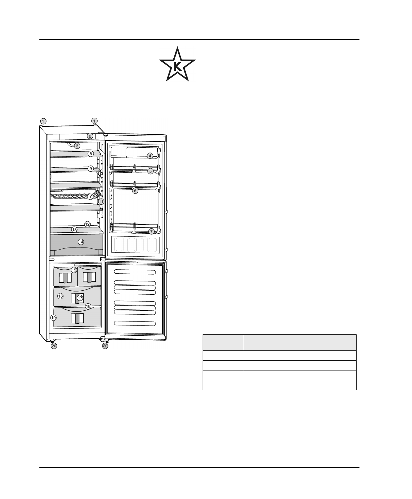
1.2 Overview of the appliance and its
equipment
The appliance at a glance
1.3 Range of appliance use
Normal use
The appliance is only suitable for refrigerating
food in a domestic environment or an environment that is similar to a domestic one. This
includes, for example, use
-
in staff kitchens, bed and breakfast establishments,
-
by guests in country homes, hotels, motels
and other types of accommodations,
-
for catering and similar wholesale services.
Use the appliance only for normal household
purposes. All other types of uses are not
permitted.
Foreseeable misuse
The following uses are specifically prohibited:
-
Storage and cooling of medication, blood
plasma, laboratory preparations or similar
substances and products in accordance with
the CMDCAS and FDA 510(k)
-
Use in areas at risk of explosion
Incorrect appliance use can cause damage to
the stored products or cause them to spoil.
Climate ratings
The appliance is set to operate within specific
ambient temperature limits according to its
climate rating. The climate rating for your appliance is printed on the rating plate.
Note
Compliance with the specified ambient
u
temperatures is required, otherwise the refrigeration performance is reduced.
Climate
Fig. 1
(1) Rear transport
handles
(2) Operating and control
elements
(3) Fan (13)Coldest zone
(4) Container shelf (14)Vegetable drawer
(5) Door rack, moveable (15)IceMaker*
(6) Bottle partition,
adjustable
(7) Gallon-capacity rack (17)InfoSystem
(8) Shelf, moveable (18)VarioSpace
(9) Shelf, can be split (19)Rating plate
(10)Bottle shelf (20)Adustable feet, front
* Depending on model and options 3
(11)Interior light
(12)Drain hole
(16)Freezer compartment
transport handles, rear
transport castors
rating
SN 50 °F (10 °C) to 90 °F (32 °C)
N 61 °F (16 °C) to 90 °F (32 °C)
ST 61 °F (16 °C) to 101 °F (38 °C)
T 61 °F (16 °C) to 110 °F (43 °C)
1.4 Conformity
The refrigerant circuit has been tested for leaks. The
appliance complies with the relevant safety regulations
and the directives UL250 and CAN/CSA C22.2 No.63-93.
Instructions for testing institutes:
Tests must be carried out in accordance with the applicable standards and guidelines.
for ambient temperatures from
General safety information
The preparation and testing of the appliance must be
carried out taking account of the manufacturer's
loading plans and the instructions in the operating
manual .
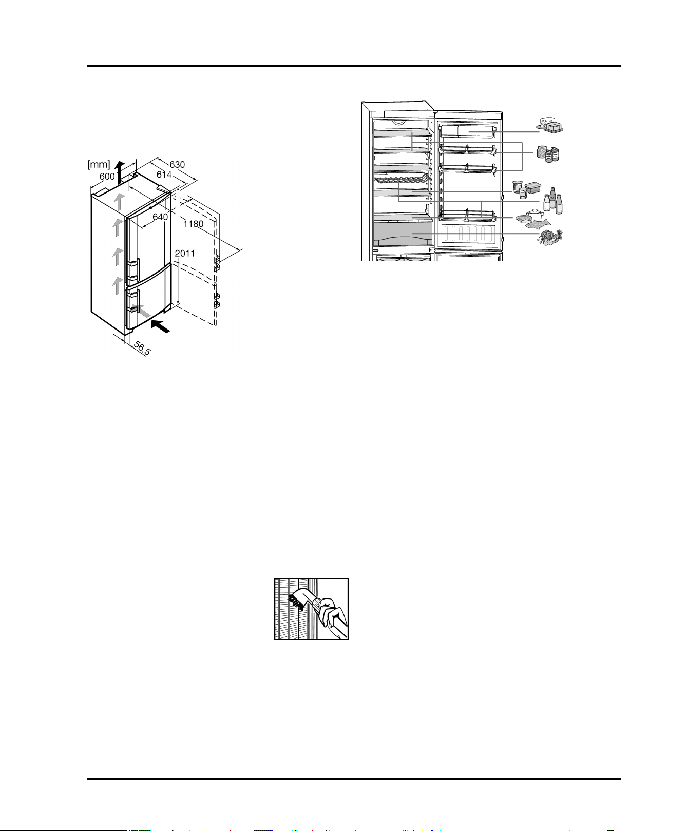
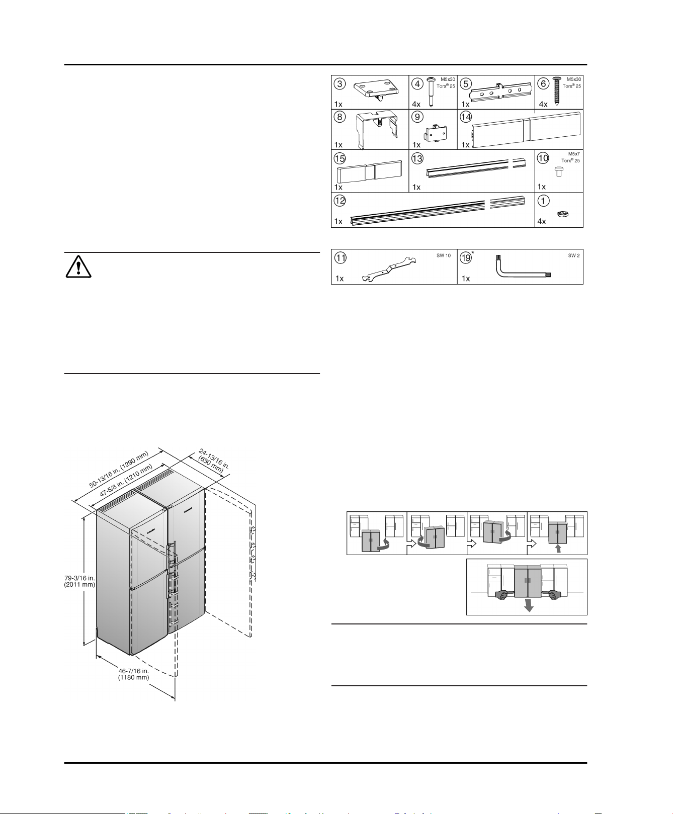
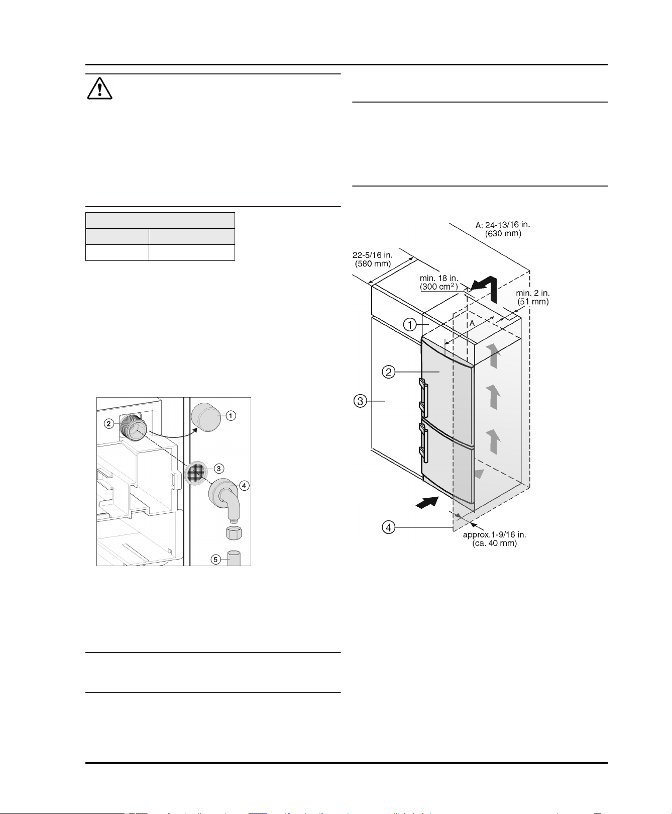
1.5 Installation dimensions
Fig. 2
1.6 Energy saving
Always ensure good ventilation. Do not obstruct venti-
lation openings or grilles.
Do not install the appliance in direct sunlight or next to
an oven, heater, or similar heat source.
Energy consumption depends on installation conditions
such as the ambient temperature (see 1.3) .
Avoid opening the appliance door for any longer then
neccesary.
The lower the temperature is set the higher the energy
consumption.
All food stored in the appliance should be well wrapped
and covered. This prevents frost buildup.
Only take food out for as long as necessary so that it
does not get too warm.
Storing hot food: let it cool to room temperature first.
Defrost frozen food in the fridge.
-
Dust deposits increase energy
consumption:
Once a year the dust should be
removed from the refrigerating
machine and the heat exchanger
metal grid at the back of the appliance.
1.7 Example of food arrangement
Fig. 3
2 General safety information
Read and follow these instructions. They contain
safety advice which is important for safe and
problem-free installation and operation. Always
read and follow the safety advice.
Dangers for the user:
-
This appliance can be operated by children 8
years and older as well as by persons with
reduced physical, sensory or mental capabilities or lack of experience and knowledge if
they are supervised or have been instructed in
the safe use of the appliance and understand
the associated risks. Children must not play
with the appliance. Cleaning and user maintenance must not be performed by children
unless they are supervised.
-
When disconnecting the appliance from the
outlet, always take hold of the plug. Do not pull
on the cable.
-
Disconnect the power plug or switch off the
power if a fault occurs.
-
Do not damage the mains power line. Do not
operate the appliance from a defective mains
power line.
-
Repairs, work on the appliance and replacement of the power cord should only be carried
out by the customer service department.
-
The appliance should only be assembled,
connected and disposed of in accordance with
the instructions.
-
Please keep the instructions and pass them on
to any future owner.
-
All repairs to or work on the IceMaker must
only be carried out by the customer service
4 * Depending on model and options
Controls and displays
department or other specialist engineers
trained to do this.*
-
The manufacturer is not liable for damage
arising from incorrect connection to the water
supply.*
Risk of fire:
-
Do not operate the appliance near explosive
gases.
-
Do not store explosive materials or spray cans
with flammable propellants, such as e.g.
butane, propane, pentane, etc. in the appliance. You can recognize such spray cans by
the printed contents or a flame symbol. Any
leaking gasses can be ignited by electrical
components.
-
Keep burning candles, lamps and other
objects with open flames away from the appliance so that they do not set it on fire.
-
Alcoholic beverages or other containers
holding alcohol must always be tightly sealed
for storage purposes. Any leaking alcohol can
be ignited by electrical components
Tipover hazard:
-
Do not stand or climb on the base, drawers,
doors, etc. This applies in particular to children.
Risk of food poisoning:
-
Do not consume food that has passed its best
before date.
Danger of frostbite, feelings of numbness
and pain:
-
Avoid continued skin contact with the cold
surfaces or chilled/frozen food or adopt protective measures, e. g. use gloves. Do not
consume ice cream (especially sherbets) and
ice cubes immediately when they are too cold.
Risk of injury and damage:
-
Hot steam may lead to injuries. Do not use any
electrical heating or steam cleaning equipment, naked flames or defrosting sprays for
defrosting
-
Do not remove ice with sharp objects
Risk of crushing
-
Do not reach into the soft stop mechanism.
Fingers may be trapped when the door is
closed.
Follow the specific instructions in the other
sections:
DANGER indicates a hazardous situation,
which if not avoided, will result in
death or serious injury.
WARNING indicates a hazardous situation,
which if not avoided, could result in
death or serious injury.
CAUTION indicates a hazardous situation,
which if not avoided, will result in
minor or moderate injury.
NOTICE indicates a hazardous situation,
which if not avoided, could result in
damage to property.
Note indicates useful advice and tips.
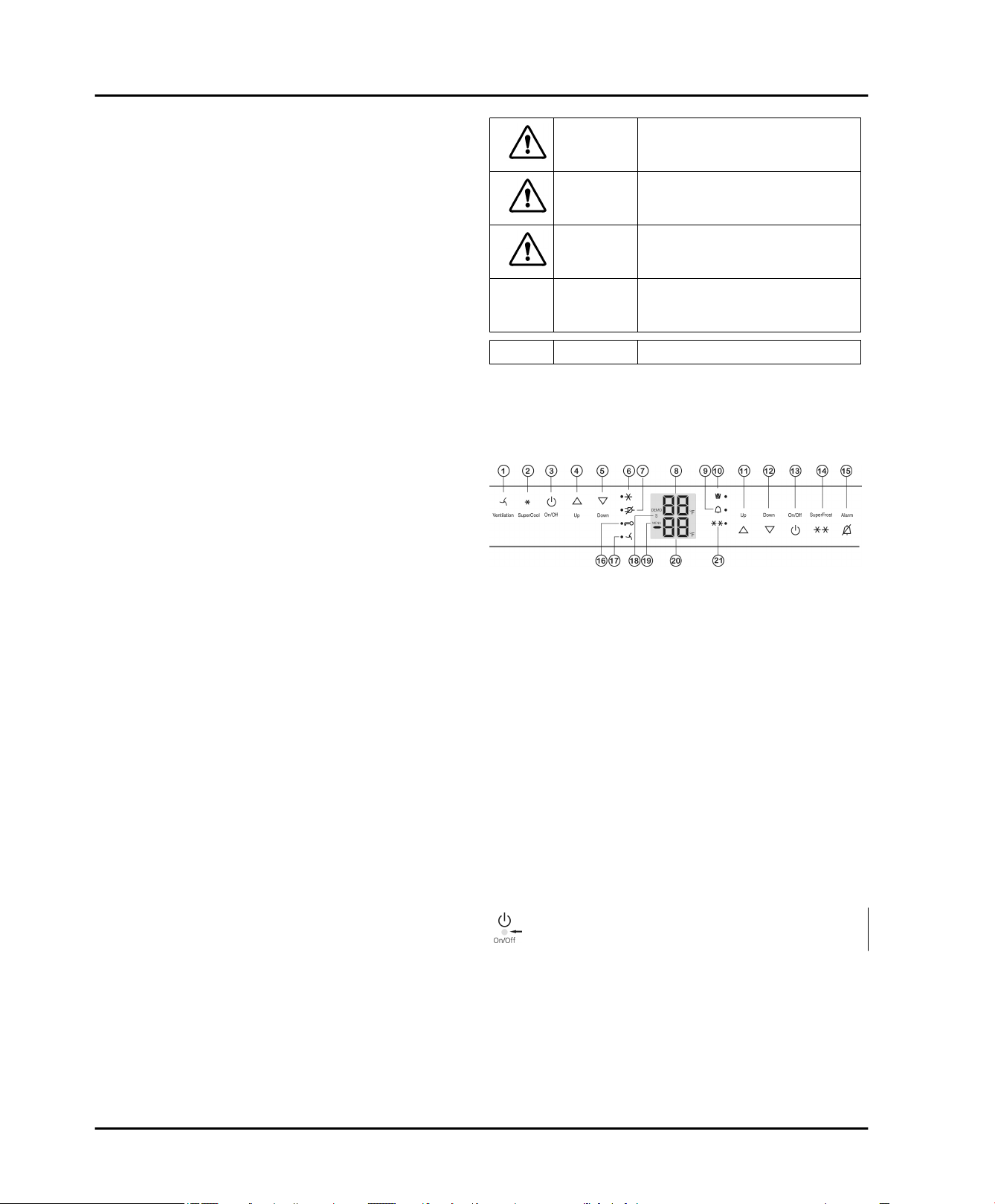
3 Controls and displays
3.1 Operating and control elements
Fig. 4
(1) Ventilation button (12)Freezer compartment
Down button
(2) SuperCool button (13)Freezer compartment
On/Off button
(3) Fridge compartment
On/Off button
(4) Fridge compartment
Up button
(5) Fridge compartment
Down button
(6) SuperCool symbol (17)Ventilation symbol
(7) Power failure symbol (18)Sabbath mode symbol
(8) Fridge compartment
temperature display
(9) Alarm symbol (20)Freezer compartment
(10)IceMaker symbol* (21)SuperFrost symbol
(11)Freezer compartment
Up button
The touch point is located between the symbol and the
symbol label.
3.2 Temperature display
The following is displayed in normal operation:
the highest freezer temperature
the average fridge temperature
-
The freezer compartment temperature display is flashing:
the temperature setting has been changed
-
(14)SuperFrost button
(15)Alarm button
(16)Child lock symbol
(19)Menu symbol
temperature display
* Depending on model and options 5
Start-up
after switch-on the temperature is not yet cold enough
the temperature has risen several degrees
-
Dashes are shown on the display:
the freezer temperature is above 32 °F (0 °C).
-
The following displays indicate malfunction. Possible
causes and corrective actions: (see Troubleshooting).
-
F0 through F9
-
FE*
The power failure symbol LED
flashes.
4 Start-up
4.1 Transporting the appliance
WARNING
Danger of fire and damage due to blocked ventilation
openings!
Never block the ventilation openings. Always ensure
u
good ventilation!
NOTICE
Risk of damage caused by condensation
Installing the appliance next to any other refrigerator or
freezer can cause condensation or damage to the Liebherr appliance.
Do not install this appliance next to any other refriger-
u
ator or freezer except another Liebherr model. Liebherr
models are designed to allow side-by-side installation.
They are equipped with a heating system to eliminate
condensation when refrigerators or freezers are
installed side-by-side.
CAUTION
Risk of injury or damage if incorrectly transported.
Transport the appliance in its packaging.
u
Transport the appliance upright.
u
Do not move the appliance on your own.
u
4.2 Setting up the appliance
WARNING
Risk of fire due to moisture!
If live parts or the power cord get wet, this can cause a
short circuit.
The appliance is designed for use in enclosed spaces.
u
Do not operate the appliance in open space or in damp
areas or where there is spray.
WARNING
Risk of fire due to short circuit.
If the power cable or plug of the appliance or another
appliance and the back of the appliance touch each other
the power cable or plug will be damaged by the vibrations
of the appliance which could lead to a short circuit.
Install the appliance so that it does not touch any plugs
u
or power cables.
Do not connect the appliance or other appliances to the
u
sockets on the back of the appliance.
NOTICE
Risk of damage for the finished floor surface!
Protect the finished floor surface before you uncrate the
u
unit.
Verify that:
The floor under the appliance is flat and level.
q
The floor can support the appliance's weight plus
q
approximately 1200 pounds (544 kg) of food weight.
The appliance is not placed in direct sunlight or near
q
the stove, range top, radiators and similar heat
sources.
Examine the unit and packaging for shipping damage.
u
Contact the carrier immediately if you suspect there is
any damage.
Note the type (model, number), index, appliance/serial
u
number, date of purchase and where purchased
(see 6.6) .
Remove anything attached to the rear or side walls of
u
appliance that would prevent proper installation or
impede proper ventilation.
Remove the protective film from the outside of the
u
appliance.
NOTICE
The stainless steel doors are treated with a high-grade
surface coating and must not be cleaned with the
supplied cleaning agent.
This would damage the surface coating.
Wipe the coated door surfaces using a soft, clean
WARNING
Danger of fire and damage!
Do not place devices that give off heat, e.g. micro-
u
waves, toasters, etc. on the appliance.
CAUTION
Risk of personal injury!
Have two people move this appliance into place.
u
6 * Depending on model and options
u
cloth only.
Apply a stainless steel cleaner only to the stainless
u
steel side walls evenly, wiping with the grain. Subsequent cleaning becomes easier as a result.
Wipe painted side walls with a clean, soft cloth only.
u
Align the appliance so that it
u
stands firmly and on a level
by applying the accompanying spanner to the adjustable-height feet (A) and
using a spirit level.
Then support the door:
u
Extend the adjustable foot
at the turn hinge (B) until it
rests on the floor and then
make a further 90° turn.
Start-up
Note
Clean the appliance (see 6.3) .
u
If the appliance is set up in humid areas, condensation
may build on the outside of the appliance.
Always ensure proper ventilation.
u
4.3 Changing the door hinges
You can reverse the door hinges, if necessary:
Make sure you have the following tools on hand:
Torx® 25
q
Torx® 15
q
Screwdriver
q
Cordless screwdriver, if necessary
q
Another person to help with the installation, if neces-
q
sary
SW2 Allen key (supplied)
q
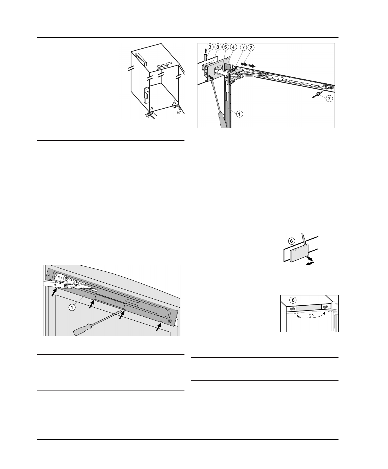
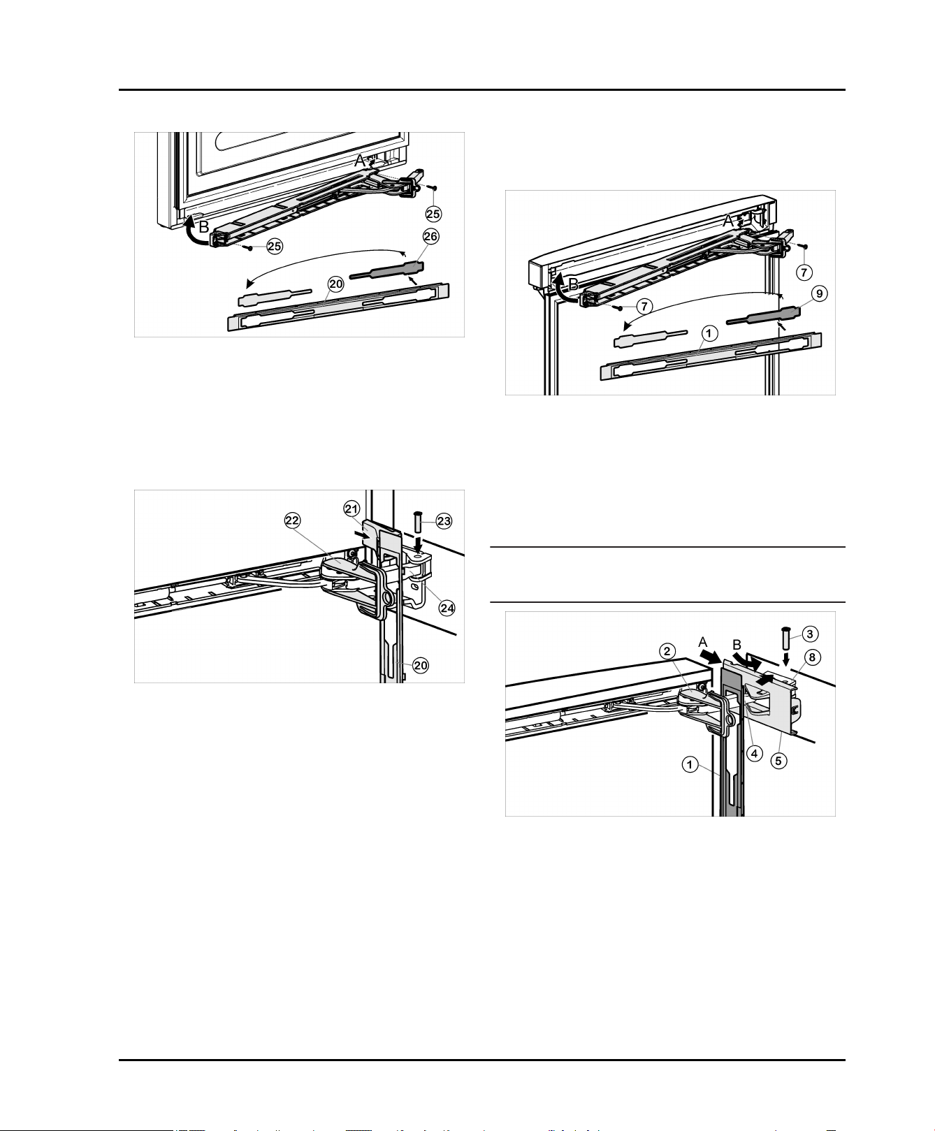
4.3.1 Remove upper soft stop damper
Fig. 5
Open upper door.
u
NOTICE
Risk of damage!
If the door seal is damaged the door may not close properly and the level of cooling is insufficient.
Do not damage the door seal with the screwdriver!
u
Fig. 6
Push panel forward over the damper bracket
u
the direction of the appliance.
Engage locking device
u
oblong hole.
The locking device prevents the hinge from snapping
w
shut.
Unscrew cover
u
the first notch using a screwdriver.
The bolt will become visible.
w
Push bolt
u
Press damper bracket
u
door.
Completely loosen cover
u
side and remove.
Remove panel
u
Loosen cover that is on the
u
hinge side
screwdriver and remove by
pulling outwards.
Unscrew soft stop unit (2 x Torx® 15)
u
Slightly pull out soft stop unit, push it towards the
u
handle side and open it out.
Set soft stop unit to the side.
u
Unscrew bearing part
u
Fig. 6 (8)
move it to the opposite
side. Make preliminary
holes (optional) or use a
cordless screwdriver.
, turn it 180° and
Fig. 6 (5)
Fig. 6 (3)
Fig. 6 (1)
Fig. 7 (6)
Fig. 6 (2)
that is on the hinge side until
out from below.
Fig. 6 (4)
Fig. 6 (5)
.
using a
into place inside
in the direction of the
that is on the hinge
Fig. 6 (7)
Fig. 6 (4)
.
4.3.2 Removing the upper door
Note
To prevent food items from falling out, take all food out
u
of the door racks before removing the door.
in
Fig. 7
Fig. 8
Release panel
u
remove.
The panel hangs above the damper bracket.
w
* Depending on model and options 7
Fig. 5 (1)
using a slotted screwdriver and
Start-up
Fig. 9
Close upper door.
u
Pull cover
u
Lift off cover
u
Fig. 9 (10)
Fig. 9 (11)
CAUTION
Risk of injury if the door tips out!
Keep a steady grip on the door.
u
Set the door down carefully.
u
Unscrew upper bearing bracket
u
25)
Fig. 9 (13)
Lift the upper door up and off and set it to the side.
u
4.3.3 Remove lower soft stop damper
forward and upwards to remove.
.
Fig. 9 (12)
and pull it upwards to remove.
(2 x Torx®
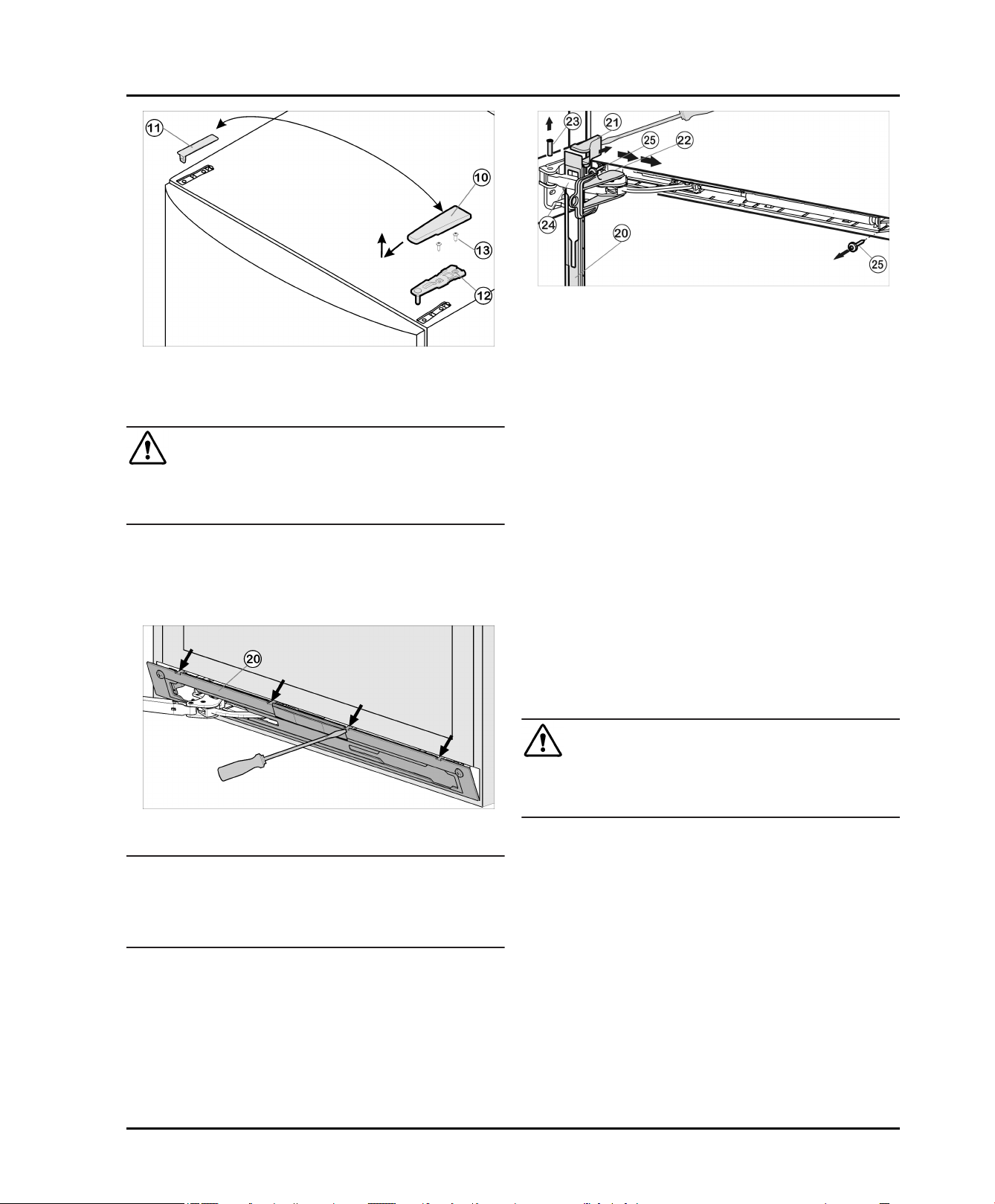
Fig. 11
Push panel forward over the damper bracket
u
Fig. 11 (24)
Engage locking device
u
in the direction of the appliance.
Fig. 11 (22)
into place inside
oblong hole.
The locking device prevents the hinge from snapping
w
shut
Lift off cover
u
Fig. 11 (21)
from the outside using a screwdriver and remove by pulling outwards.
Tip the appliance rearwards with the help of a second
u
person if needed.
Push bolt
u
Press damper bracket
u
Fig. 11 (23)
out from below.
Fig. 11 (24)
in the direction of the
door.
Remove panel
u
Unscrew entire soft stop unit (2 x Torx® 15)
u
Slightly pull out soft stop unit, push it towards the
u
Fig. 11 (20)
.
Fig. 11 (25)
handle side and open it out
Set soft stop unit to the side
u
4.3.4 Removing the lower door
.
Fig. 10
Open the lower door.
u
NOTICE
Risk of damage!
If the door seal is damaged the door may not close properly and the level of cooling is insufficient.
Do not damage the door seal with the screwdriver!
u
Release panel
u
Fig. 10 (20)
using a slotted screwdriver
and remove.
The panel hangs above the damper bracket
w
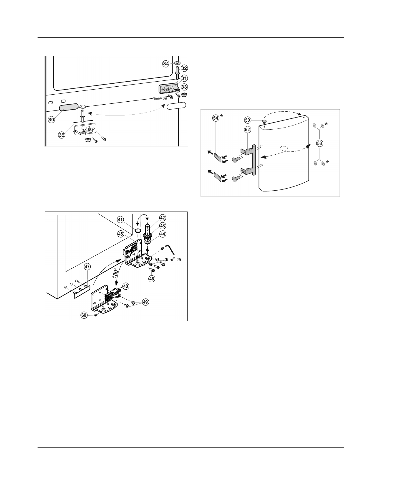
Close the lower door.
u
Pull center bearing pin
u
Fig. 12 (32)
and disc
Fig. 12 (34)
out of the bearing bracket and the lower door.
Remove plastic cap
u
Fig. 12 (33)
.
CAUTION
Risk of injury if the door tips out!
Keep a steady grip on the door.
u
Set the door down carefully.
u
Open the lower door.
u
Unscrew center bearing bracket
u
Fig. 12 (31)
(2 x Torx®
25).
Lift lower door upwards to remove and set it to the side
u
8 * Depending on model and options
4.3.5 To swap over central bearing parts
Fig. 12
Carefully remove cover trim
u
Turn the center bearing bracket
u
Fig. 12 (35)
180° and secure tightly (to 4 Nm) on the
new hinge side.
Turn the cover trim
u
Fig. 12 (30)
into place on the new handle side.
Fig. 12 (30)
180° and snap it back
.
Fig. 12 (31)
and washer
Start-up
Using a cordless screwdriver if necessary, again
u
secure the bearing bracket
Fig. 13 (45)
side tightly (to 4 Nm).
Screw complete bearing pin
u
Fig. 13 (42)
positioning foot, back into place again.
Tighten grub screw
u
Fig. 13 (60)
.
4.3.7 Swapping the handles
For both the upper and lower door:
on the new hinge
, with disc and
4.3.6 To swap over lower bearing parts
Unscrew grub screw
u
the socket wrench supplied.
Unscrew the bearing pin
u
Fig. 13 (43)
and positioning foot
upwards direction.
Lift off plug
u
Unscrew
u
Completely unscrew the grub screw
u
Fig. 13 (41)
Fig. 13 (46)
screw it into the opposite side of the bearing bracket
until it is externally flush with the bearing bracket.
Unscrew bearing part
u
tighten
Fig. 13 (49)
Insert plug
u
Carefully lift off the cover on the handle side
u
Fig. 13 (41)
and move it to the opposite side.
Fig. 13 (60)
by approx. 1 turn using
Fig. 13 (42)
Fig. 13 (44)
.
bearing bracket
Fig. 13 (48)
Fig. 13 (45)
, turn it 180° and
it to the inside.
back into the other hole.
, with disc
, in an
.
Fig. 13 (60)
Fig. 13 (47)
Fig. 13
and
Fig. 14
Pull plugs
u
Fig. 14 (50)
out of the door bearing bushes
and move them to the other side.
Detach the door handle
u
pressure plates*
Fig. 14 (52)
Fig. 14 (54)
, plug
Fig. 14 (53)
and move them to the
opposite side.
When fitting the pressure plates on the opposite side,
u
make sure they engage correctly.*
4.3.8 Fitting the lower door
Position the lower door from above onto the lower
u
bearing pins
Close the door.
u
Place the plastic cap
u
bearing bracket
Insert the center bearing pin
u
Fig. 13 (42)
Fig. 12 (31)
hinge side through the center bearing bracket
Fig. 12 (31)
Place disc
u
Fig. 12 (32)
into the lower door.
Fig. 12 (34)
.
.
Fig. 12 (33)
back onto the center
.
Fig. 12 (32)
on the new
onto the center bearing pin
and
* Depending on model and options 9
Start-up
4.3.9 Fitting the lower soft stop damper
Fig. 15
Loosen cover
u
Fig. 15 (26)
insert on the other side.
With the hinge of the soft stop unit facing the door
u
hinge side, engage the soft stop unit (A) and swivel
inwards (B)
The holes on the left and right must lie exactly above
w
each other
Tighten soft stop unit (2 x Torx® 15)
u
from the panel
Fig. 15 (25)
Fig. 15 (20)
.
and
Snap both cover
u
Fig. 9 (11)
and cover
Fig. 9 (10)
place on the opposite side.
Leave upper door open.
u
4.3.11 Fitting the upper soft stop damper
Fig. 17
Loosen cover
u
insert on the other side.
With the hinge of the upper soft stop unit facing the
u
door hinge side, engage the soft stop unit (A) and
swivel inwards (B)
The holes on the left and right must lie exactly above
w
each other
Tighten soft stop unit (2 x Torx® 15)
u
Fig. 17 (9)
from the panel
Fig. 17 (7)
Fig. 17 (1)
.
into
and
Fig. 16
Hook panel
u
Fig. 16 (20)
into the damper bracket such
that the detent hooks are pointing forwards and the
front side is facing the appliance.
Pull damper bracket
u
bracket and insert bolt
Fig. 16 (24)
Fig. 16 (23)
from above such that
towards bearing
the square is resting in the recess.
Position cover
u
Check that the cover is positioned correctly such that
w
Fig. 16 (21)
and snap in.
the door can close properly and the bolt is secured
Remove locking device
u
Snap panel
u
Close the lower door.
u
Fig. 16 (20)
Fig. 16 (22)
by twisting it.
into place on the door.
4.3.10 Fitting the upper door
Place the upper door onto the center bearing pin
u
Fig. 12 (32)
Insert the upper bearing bracket
u
hinge side into the door.
Tighten the upper bearing bracket (to 4 Nm)(2 x Torx®
u
25)
Fig. 9 (13)
a cordless screwdriver.
.
Fig. 9 (12)
on the new
. Make preliminary holes (optional) or use
Note
Follow the correct sequence First hang the panel over
u
the damper bracket, then the cover
Fig. 18
Hook panel
u
Fig. 18 (1)
into the damper bracket
Fig. 18 (4)
such that the detent hooks are pointing inwards and the
front side is facing the appliance.
Push on cover
u
over the bearing part
Place cover
u
Fig. 18 (5)
Fig. 18 (8)
Fig. 18 (5)
from the outside (A) and pivot
(B).
on top and allow to snap into
place until the first notch.
The openings for the bolts lie above each other after
w
positioning the damper bracket
Pull damper bracket
u
and insert bolt
Fig. 18 (4)
Fig. 18 (3)
towards bearing bracket
from above such that the
square is resting in the recess.
10 * Depending on model and options
Start-up
Now snap cover
u
bearing part
Check that the cover is positioned correctly such that
w
the door can close properly and the bolt is secured
Remove locking device
u
Snap panel
u
Turn cover
u
on top from the outside and snap into place.
Fig. 18 (5)
Fig. 18 (8)
Fig. 18 (1)
Fig. 7 (6)
completely into place on the
.
Fig. 18 (2)
into place on the door.
180° from the handle side, place it
by twisting it.
4.3.12 Aligning the doors
Align the doors flush with the appliance housing, using
u
the two oblong holes in the lower bearing bracket
Fig. 13 (45)
as a guide, if needed. To do so, unscrew the center
screw on the lower bearing bracket
Risk of bodily injury due to the door falling off.
If the bearing parts are not installed with the proper
torque, the door may fall off. In addition, the door may not
close, thus impairing the cooling performance of the appliance.
Securely tighten the bearing brackets by applying a
u
torque of 3 lb-ft (4 Nm).
Check all screws and retighten if necessary.
u
and in the center bearing bracket
WARNING
Fig. 12 (31)
Fig. 13 (45)
.
4.4 Side-by-side installation
As seen from the front, install the appliance with an
IceMaker on the right and the appliance without an
IceMaker on the left.
Fig. 20
Fig. 21
Make sure you have the following tools on hand:
Spirit level
q
Cordless screwdriver
q
Torx® 25 screwdriver
q
Open-end wrench, SW 10 (supplied)
q
1/4 in. socket
q
Allen wrench, SW 2 (supplied)
q
Tips on moving the combination:
Before assembly, set the appliances up as close as
q
possible to the final location.
When moving the appliances, always grasp the front
q
outside corners. Never press your knee against the
side walls or door.
The easiest way to move the combination is diagonally,
q
by moving the left and right corner in turn.
If the combination is positioned exactly in front of the
recess, slide it in straight.
If you need to pull the
q
combination back out of
the recess, grasp it in the
bottom third and pull
forward.
NOTICE
Moving the SBS combination may result in damage!
The assembled SBS combination is heavy. If not moved
properly, the appliance may become dented.
Read and follow the moving tips (see above).
u
Remove all protective films from the housing exterior.
Fig. 19
The fixing accessories are supplied with model CS 1311.
If you have model CS 1360 you can purchase the fixing
accessories by contacting customer services.
* Depending on model and options 11
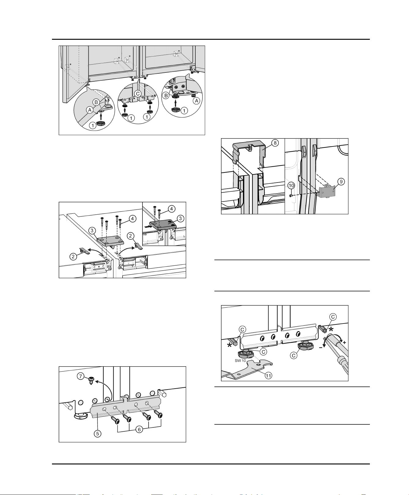
u
Front of the appliance:
Start-up
Fig. 22
If necessary screw in the adjustment feet
u
the front of both appliances completely so that there is
no floor contact.
Place the caps
u
Fig. 22 (1)
on the four front adjustment
feet.
Move both units together so that there is a gap of up to
u
approx. 3/8 " (10 mm) between them so that they are
flush as seen from the front.
Fig. 22 (A)
The appliances are automatically aligned in depth with the
connecting sheet. If one appliance projects further
forward than the other start with this one. Otherwise start
with the left hand appliance.
Fix the connecting sheet
u
ance with two screws
Move the connecting sheet to the side so that the
u
Fig. 24 (5)
Fig. 24 (6)
loosely to one appli-
.
centre bar of the sheet is touching the side wall of the
appliance. Tighten the screws.
Screw the connecting sheet to the second appliance
u
too. If necessary push the appliances together or apart
a little.
Back of the appliance:
at
Fig. 23
Release and remove the covers
u
Fig. 23 (2)
.
The appliances are automatically aligned in height with
the connecting plate. If one appliance is somewhat higher
than the other start with this one.
Fit a connecting plate
u
appliance with two screws
Move the connecting plate to the side so that the centre
u
Fig. 23 (3)
Fig. 23 (4)
and fix loosely to one
.
bar of the plate is touching the side wall of the appliance. Tighten the screws.
Screw the connecting plate to the second appliance
u
too. If necessary push the appliances together or apart
a little.
Fig. 25
Place the connecting clamps
u
Fig. 25 (8)
at the top of the
centre side walls.
Insert theconnecting angle
u
Fig. 25 (9)
underneath into
the corresponding space.
If the connecting angle is somewhat loose, fit a screw
u
Fig. 25 (10)
.
Note
To prevent vibration noise, the brackets and screws
u
must not come into contact with the clamps or the
screws on the pipework on the back.
Front of the appliance:
Fig. 26
NOTICE
Risk of damage to the castors.
Do not use a power tool to adjust the rear adjustment
u
feet as it will damage the leveling mechanism or disengage the rod – instead use a hand ratchet.
The front adjustment feet can be adjusted with the
Fig. 24
If your appliance has been fitted with the pre-fitted
u
screw
Fig. 24 (7)
12 * Depending on model and options
: Undo the screw.
supplied open-end wrench
ment feet* with a 1/4'' bit attachment.
Fig. 26 (11)
and the rear adjust-
Start-up
Tighten the centre adjustment feet
u
Fig. 22 (C)
so that
there is no floor contact.
Align the combination with the outer adjustment feet
u
Fig. 22 (B)
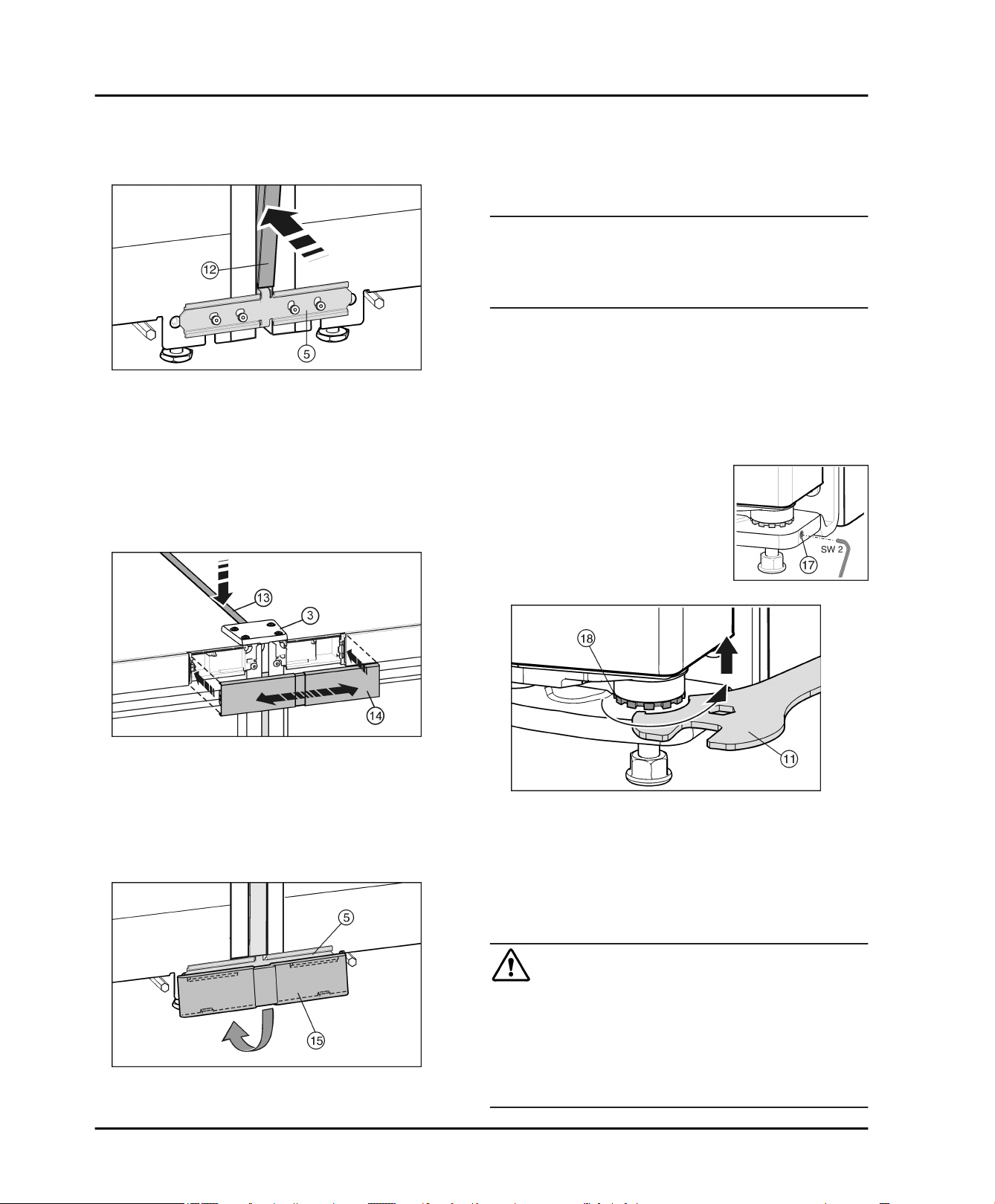
Before inserting the trim
.
Fig. 27
Fig. 27 (12)
squeeze the two fillets
together along the entire length. The trim can now be
inserted more easily into the gap. When pressing in the
trim, use a soft cloth to prevent dents on the surface of the
trim. Press the trim carefully and evenly into the gap to
achieve the best possible fit.
On the front press the long trim
u
Fig. 27 (12)
into the
vertical gap. Ensure that the trim rests on the
connecting panel
Remove protective film from the trim.*
u
Fig. 27 (5)
.
Connect the combination unit to the power supply
u
(see 4.10) .
Appliances with IceMaker:
Connect the appliance to the water supply (see 4.5) .
u
All appliances
Fit the anti-tip device (see 4.7) .
u
NOTICE
Moving the SBS combination may result in damage!
The assembled SBS combination is heavy. If not moved
properly, the appliance may become dented.
Read and follow the moving tips (see above).
u
Carefully push the combination into the designated
u
position.
Align the combination again if necessary using the
u
adjustment feet.
Lower thecentre adjustment feet
u
Fig. 22 (C)
again until
they touch the floor.
Then shore up the door: Lower theadjutment feet
u
Fig. 22 (A)
onto the bearing bracket until they contact
the floor then turn 90° again.
The door height can be
adjusted at the lower outside
bearing brackets:
Unscrew the threaded pin
u
Fig. 30 (17)
a little (no more
than one turn).
Fig. 28
On the top, press the short trim
u
Fig. 28 (13)
into the gap.
The trim must form a flush finish with the connecting
plate
Fig. 28 (3)
Snap the cover
u
on the front edge.
Fig. 28 (14)
onto the open space
between the two control panel trims. Make sure that the
outer surfaces of the cover form a flush finish with the
control panel trims. The cover can be extended for this
purpose.
Fig. 29
Position the lower cover
u
connecting panel
Fig. 29 (15)
Fig. 29 (5)
and snap it down into place.
from above onto the
To lift the door unscrew the bearing pin
u
Fig. 31 (18)
clockwise using the supplied open-end wrench
Fig. 31 (11)
. The appliance is delivered from the factory
with the bearing pin screwed in completely.
Screw the threaded pin
u
Fig. 30 (17)
in again to fix the
bearing pin.
4.5 Water connection*
WARNING
Electrical Shock Hazard!
Do not make the water connection while the appliance
u
is connected to an electrical outlet.
Disconnect the water supply before connecting the
u
water lines for the IceMaker.
The connection to the water supply may only be made
u
by a trained and licensed plumber.
Fig. 30
Fig. 31
* Depending on model and options 13
Start-up
WARNING
Poisoning Hazard!
The water quality must comply with the drinking water
u
regulations for the geographical area where the appliance is located.
Connect to potable water supply only.
u
The IceMaker is designed exclusively to make ice
u
cubes in quantities needed by a household and must
only be operated with water appropriate for this
purpose.
Water pressure:
psi MPa (bars)
21.76 to 87.02 0.15 to 0.6 (1.5 to 6)
If a water filter is used, the instructions on water pressure
in the Installing the water filter section apply.
- Water must be supplied to the appliance through a cold
water pipe that complies with hygiene standards and
can withstand the operating pressure.
- All devices and equipment used to supply water must
comply with the regulations in force in the respective
country.
- The solenoid valve is located at the bottom of the back
of the appliance. It has a metric R3/4 connecting
thread.
Have the water line bled (remove air) by a competent
u
professional.
NOTICE
Malfunction of the water intake!
If the water intake is shut off during operation but the
IceMaker remains in operation, the water intake pipe may
ice up.
Switch off the IceMaker if the water supply is inter-
u
rupted (e.g. holiday).
4.6 Installation into a fitted kitchen
Fig. 33
(1) Top cupboard (3) Kitchen cabinet
(2) Appliance (4) Wall
The appliance can be built into the range of kitchen units.
To bring the appliance
fitted kitchen units, a suitable top cupboard
Fig. 33 (2)
up to the height of the
Fig. 33 (1)
can
be added above the appliance.
When installing with kitchen cabinets (max.
depth. 22-27/32 '' (580 mm)) the appliance can be
installed right next to the kitchen cabinet
Fig. 33 (3)
. The
appliance door projects 1-11/32 '' (34 mm) at the side and
in the center of the appliance 1-31/32 '' (50 mm) from the
front of the kitchen cabinet. This allows it to open and
Remove the cap
u
Fig. 32 (2)
Ensure that the gasket
u
.
elbow connection
Connect the elbow adapter
u
valve
Fig. 32 (2)
Fig. 32 (1)
Fig. 32 (4)
and tighten with an open-ended
wrench, for example.
NOTICE
Risk of thread damage!
Do not overtighten.
u
Fig. 32
from the solenoid valve
Fig. 32 (3)
is inserted in the
supplied.
Fig. 32 (4)
to the solenoid
close properly.
Connect the domestic water supply
u
copper pipe) to the elbow connector
Fig. 32 (5)
Fig. 32 (4)
Before fitting into the cabinet:
Check the whole water system for leaks.
u
Before using for the first time:
14 * Depending on model and options
(e.g.
.
Ventilation requirements:
There must be a ventilation shaft at least 1-31/32 ''
-
(50 mm) deep at the back of the top cupboard over the
entire width of the top cupboard.
The cross section of the ventilation gap below the
ceiling must be at least 46.5 in 2 (300 cm 2).
The bigger the ventilation gap, the more energy-saving
the operation of the appliance.
If the appliance is installed with the hinges next to a wall
Fig. 33 (4)
must be at least 1-9/16 '' (40 mm). This is how far the
handle protrudes when the door is open.
, the gap between the appliance and the wall
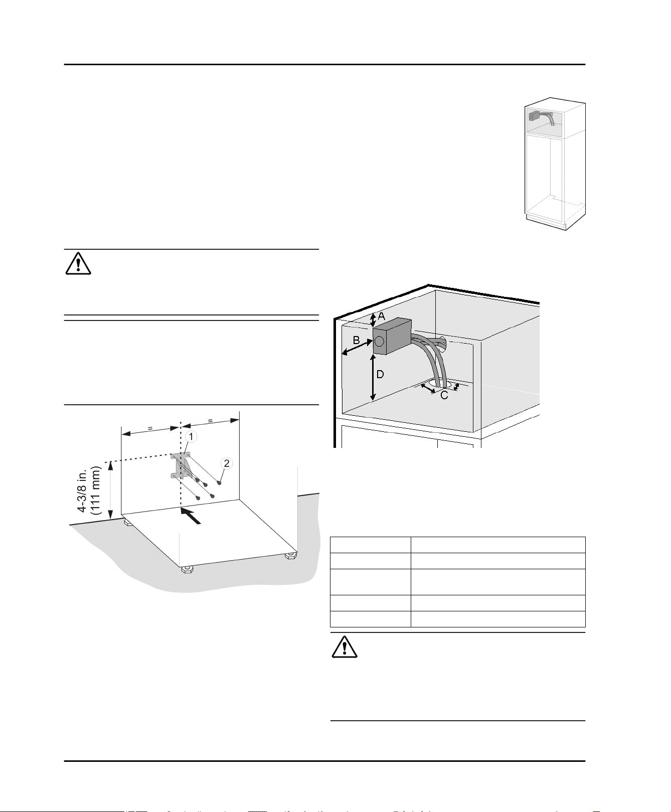
4.7 Anti-tip device
The screws for fastening the anti-tip device are not
supplied with the appliance. Appropriate screws must be
used for the material (wood, concrete, etc.) in which the
safety device is mounted.
WARNING
Risk of injury if the appliance tips over!
Install the anti-tip device to prevent the appliance from
u
tipping over when the fully loaded door is open.
NOTICE
Risk of damage due to leaking water!
If the tilt safety device has been fitted in another position
than the one given, the water hoses may be damage
when pushing the appliance into the niche.
Only fit the tilt safety device in the position shown in the
u
diagram.
Start-up
4.8 Installing the water filter*
The water filter ensures optimum water
quality and is available as an accessory. It
should be installed near the appliance in
the cabinet, for example in the adapter
cabinet above the appliance. To connect
the filter to the appliance, it may be necessary to make an opening (C) in the floor of
the adapter cabinet through which the
hoses will be routed. Depending on your
installation setup, you can route the two
water filter hoses either through the rear
panel or through the base of the cabinet.
The maximum length of the water hose
is118-1/8 '' (3 m).
Alternatively, the appliance can also be
operated without the water filter.
Mark the installation position for the anti-tip device on
u
the wall or back of the unit.
Install the anti-tip device
u
screws
Fig. 34 (2)
.
Fig. 34 (1)
using appropriate
Fig. 34
Fig. 35
(A) 13/16 in (20mm) (C) 1-3/16in. x 3/8in.
( 30mm x 10mm )
(B) 3-15/16 in (100mm) (D) min. 4 in (100mm)
The filter cover must be installed during assembly, so
leave sufficient space around the filter module. Maintain
the dimensions shown in
replaced and the cover can be removed.
Flow rate 0.5 gpm (1.89 lpm)
Water connection Drinking water
Water pressure 40 psi - 90 psi ( 2.8 bar - 6.2 bar/ 0.28 MPa
Water temperature 33 °F - 100 °F ( 0.6 °C - 37 °C )
Capacity 300 gal. (1.14 l)
WARNING
Consuming contaminants can be harmful to your health!
If there is a chance the water may contain harmful
u
bacteria or if the water quality is unknown, do not use
this system without appropriate disinfection measures
upstream or downstream of the system.
Fig. 35
- 0.62 MPa )
so that the filter can be
* Depending on model and options 15
Start-up
NOTICE
Leakage water may damage the system!
Do not install this system on hot water lines. The
u
maximum operating temperature of the water in this
system is 100 °F (37.7 °C).
This system MUST be installed and used in compli-
u
ance with federal and local installation regulations.
Do not install under water hammer conditions. A water
u
hammer arrestor must be used to prevent water
hammering. If you are unsure how to check these
conditions, consult a professional installer.
Do not install with a water pressure greater than 90 psi
u
(6.2 bar). If your water pressure exceeds 80 psi, install
a pressure limiting valve. If you are unsure how to
check the water pressure, consult a professional
installer.
Protect against frost; if temperatures below 33 °F
u
(0.6 °C) are expected, remove the filter.
When used as indicated, the disposable filter
u
cartridges must be replaced every 6 months or whenever you notice a considerable decrease in the flow
rate.
Disconnect the appliance from the mains.
q
Close off the main water supply if the appliance has
q
already been connected to the tap.
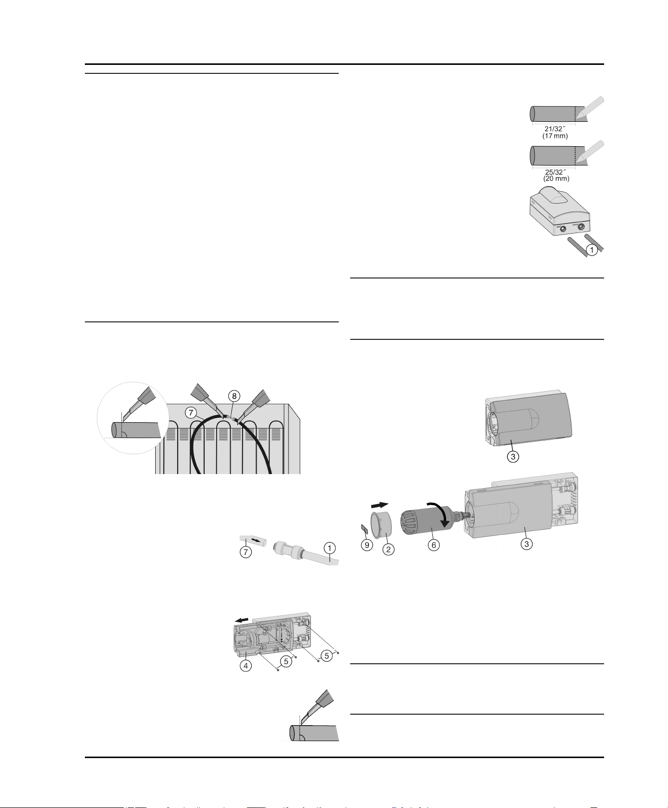
Position appliance in front of the recess.
q
Make sure the hoses do not become kinked and the
cross-section of the hose remains round.
On the thin hose measure the inser-
u
tion depth (E) of 21/32 '' (17 mm) and
make a mark.
On the thick hose measure the inser-
u
tion depth (E) of 25/32 '' (20 mm) and
make a mark.
Insert the hoses
u
Fig. 39 (1)
into
the water filter module as far
as they will go (i.e. to the mark
you made) past the point of
resistance.
Fig. 39
Note
If you need to disassemble the unit: Push back the dark
u
grey ring on the connector and hold it in this position.
While still holding the ring back, briefly push the hose
into the connector, then pull it out.
Insert the power cable into the socket (see 4.10) .
u
Connect appliance to the water supply (see 4.5) .
u
Make sure the filter is leak-tight and no water is coming
u
out.
Place the tray cover
u
Fig. 41 (3)
into position.
Fig. 36
Slice open the water hose
u
Fig. 36 (7)
located behind the
appliance both in front of and behind the connector
Fig. 36 (8)
(90° to direction of hose).
When doing so, make sure the hose does not become
kinked and the cross-section of the hose remains round.
Connect the supplied exten-
u
sion hoses
Fig. 37 (1)
appliance hoses
Slide the appliance hoses
to the
Fig. 37 (7)
:
Fig. 37
into the connectors as far as
they will go (approx. 25/32 ''
(20 mm)).
Pull the tray
u
Fig. 38 (4)
out
until it catches.
Secure the module with 4
u
screws
Fig. 38 (5)
through
the recesses in the front
and directly through the
module in the back.
Shorten hoses if necessary (90° to direc-
u
Fig. 38
tion of hose). The hoses should be long
enough to allow the appliance to be
pulled out of the recess even when it is
connected to the water filter.
Fig. 41
Remove the film from the water filter
u
Insert the water filter
u
Fig. 41 (6)
Fig. 41 (6)
and turn it approximately
.
100° to the right until it locks into position.
Place the cover on the filter
u
Slide the tray in.
u
Write the date of the next filter replacement on the
u
supplied adhesive label
Fig. 41 (2)
Fig. 41 (9)
.
and affix it to the
module.
Note
New water filters may contain particulate matter.
Do not consume or use ice cubes produced within 72
u
hours after replacing the filter.
The water filter is now ready for use.
w
Fig. 40
16 * Depending on model and options
NOTICE
Risk of damage due to leaking water!
When pushing the appliance into the recess ensure
u
that the water connection does not bend or become
damaged.
4.9 Disposal of packaging
WARNING
Danger of suffocation from packaging materials and films!
Do not allow children to play with packaging materials.
u
The packaging is made from recyclable materials:
Corrugated card/cardboard
Parts made of foamed polystyrene
Films and bags from polyethylene
Packing bands from polypropylene
Wood frame nailed together with a polyethylene
window*
Take the packaging material to an official collection
u
point.
4.10 Connecting the appliance
WARNING
Electrical shock hazard!
Start-up should only take place once the appliance has
u
been installed according to these instructions.
Electrically ground appliance.
u
Do not ground to a gas pipe.
u
Check with a qualified electrician if you are not sure the
u
appliance is properly grounded.
Do not have a fuse in the neutral or grounding circuit.
u
Do not use an extension cord, power bar or a multiple
u
socket adapter.
Do not use a power cord that is frayed or damaged.
u
Operation
Follow all Federal, State and local electrical, fire and
building codes and ordinances when installing the
receptacle and / or the appliance.
In some communities, a wall switch is required to turn
power to the appliance ON and OFF.
To reduce the risk of fire, electric shock, or personal
injury, installation work and electrical wiring must be
done by a qualified electrician in accordance with all
applicable codes and standards, including fire-rated
construction.
The Power Plug must be easily accessible so that the
appliance can be disconnected from the mains quickly
in an emergency. It must not be behind the back of the
appliance.
4.11 Switching on the appliance
Note
To switch on the entire appliance, only the freezer
u
compartment needs to be switched on.
Switch on the appliance 2 hours before loading
with frozen food for the first time.
Do not load frozen foods until the temperature
display reads 0 °F (-18 °C).
4.11.1 Switching on the freezer compart-
ment
Press On/Off button, freezer compartment
u
The fridge compartment temperature display shows the
w
current temperature in the interior.
The freezer compartment temperature display and the
w
Alarm symbol will flash until the temperature is cold
enough. If the temperature is greater than 32 °F (0 °C),
flashing dashes will appear; if the temperature is lower
than this, the current temperature will flash on the
display.
Whenever “DEMO” appears on the display, the appli-
w
ance is running in demonstration mode. Contact the
customer service department.
Fig. 4 (13)
.
WARNING
Electrical shock hazard!
This appliance is equipped with a three-prong (grounding)
polarized plug for your protection against possible shock
hazards. Electrical Grounding Required.
Do not remove the round grounding prong from the
u
plug.
Use only an grounded adapter.
u
Wait 1 hour after installation before you plug in the
appliance. This allows the refrigerant and system lubrication to reach equilibrium.
Make sure incoming voltage is the same as the appli-
ance rating. A 110-120 Volt, 60 Hz, 15 Amp electrical
supply (20 Amp for side-by-side installations) circuit
that is controlled by a circuit breaker or fuse is required.
We recommend using a dedicated circuit for this appli-
ance to prevent electrical overload.
* Depending on model and options 17
4.11.2 Switching on the fridge compartment
Press Fridge compartment On/Off button
u
The interior light comes on when the door is opened.
w
The temperature display flashes. The fridge compart-
w
ment is switched on.
Fig. 4 (3)
.
5 Operation
5.1 Temperature display unit
The temperature display can be changed from °F to °C.
5.1.1 To change the unit
Activate setting mode: Press SuperFrost button
u
Fig. 4 (14)
w
S is displayed in the temperature display.
for about 5 seconds.
Operation
The Menu symbol
w
Using Freezer compartment Up button
u
Fig. 4 (11)
Fig. 4 (12)
To confirm: Briefly press SuperFrost button
u
Fig. 4 (14)
Using Freezer compartment Up button
u
Fig. 4 (11)
Fig. 4 (12)
To confirm: Briefly press SuperFrost button
u
Fig. 4 (14)
To exit setting mode: Press Freezer compartment
u
On/Off button
-or-
Wait 5 minutes.
u
The temperature is again displayed in the temperature
w
display.
/ Freezer compartment Down button
select °.
.
/ Freezer compartment Down button
select °F or °C.
.
Fig. 4 (19)
Fig. 4 (13)
lights up.
.
5.2 Brightness of the temperature display
You can adapt the brightness of the temperature display
to the light conditions in the room in which it is installed.
If the door is open or the control panel is used the temperature indicator lights up at maximum brightness. About 1
minute after the door is closed or no button has been
pressed on the control panel, the temperature display
goes back to the set brightness.
5.2.1 Setting the brightness
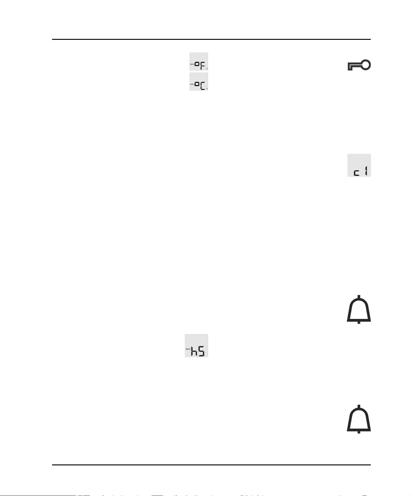
The brightness can be set between h0 (minimum luminosity) and h5 (maximum luminosity).
To activate setting mode: Press SuperFrost button
u
Fig. 4 (14)
w
S is shown on the display.
The Menu symbol
w
Press Freezer compartment Up button
u
Freezer compartment Down button
h.
To confirm: Briefly press SuperFrost button
u
To set the display brighter: Press Freezer
u
compartment Up button
To set the display darker: Press Freezer
u
compartment Down button
To confirm: Press SuperFrost button
u
Fig. 4 (14)
The brightness is set to the new value.
w
To deactivate setting mode: Press Freezer compart-
u
ment On/Off button
-or-
Wait 5 minutes.
u
The temperature is again displayed in the temperature
w
display.
for about 5 seconds.
Fig. 4 (19)
.
Fig. 4 (13)
lights up.
Fig. 4 (11)
Fig. 4 (12)
.
Fig. 4 (12)
.
.
Fig. 4 (11)
to select
Fig. 4 (14)
or
.
5.3 Child-proof lock
You can use the child-proof lock to lock the
buttons. This means that children cannot accidentally switch off the appliance when playing.
5.3.1 Switching on the child-proof lock
Activate setting mode: press and hold the SuperFrost
u
Fig. 4 (14)
button
w
S is shown on the display.
The Menu symbol
w
Using the Freezer compartment Up button
u
Freezer compartment Down button
Press the SuperFrost button
u
confirm.
When c1 is shown on the display:
To switch on the child-proof lock, press the
u
SuperFrost button
w
The Child lock symbol
flashes on the display.
When c0 is shown on the display:
To switch off the child-proof lock, press the SuperFrost
u
button
Fig. 4 (14)
w
The Child safety symbol
flashes on the display.
Deactivate setting mode: press the Freezer compart-
u
ment On/Off button
-or-
Wait 5 min.
u
The temperature is again displayed on the temperature
w
display.
for approximately 5 s.
Fig. 4 (19)
Fig. 4 (14)
briefly.
Fig. 4 (13)
lights up.
Fig. 4 (14)
briefly.
Fig. 4 (16)
Fig. 4 (16)
.
Fig. 4 (12)
LED lights up. c
Fig. 4 (11)
, select c.
briefly to
LED goes out. c
or
5.4 Door alarm
If the door is open for longer than 180 seconds,
the acoustic warning sounds.
The acoustic warning stops automatically when
the door is closed.
5.4.1 Switching off the door alarm
The acoustic warning can be switched off when the door
is open. The acoustic warning remains switched off as
long as the door is open. When the door is closed, the
alarm function is active again.
Press Alarm button
u
The door alarm stops.
w
Fig. 4 (15)
.
5.5 Temperature alarm
If the freezer temperature is not cold enough,
the audible warning sounds.
At the same time, the temperature display and
the Alarm symbol
Fig. 4 (9)
LED will flash.
The cause of a temperature being too high may be:
Hot fresh food was placed in the appliance.
-
18 * Depending on model and options
Operation
When sorting and removing food from the appliance,
too much warm ambient air got in.
The power was cut off for a while.
The appliance is faulty.
-
The audible warning automatically ceases, the Alarm
symbol
stops flashing when the temperature is cold enough
again.
If the alarm status remains: (see Troubleshooting).
Note
If the temperature is not cold enough, food may spoil.
u
Fig. 4 (9)
Check the quality of the food. Do not consume spoiled
food.
goes out, and the temperature display
5.5.1 Switching off the temperature alarm
The acoustic warning can be switched off. When the
temperature is cold enough again, the alarm function is
active again.
Press Alarm button
u
The acoustic warning ceases.
w
Fig. 4 (15)
.
5.6 Sabbath Mode
After entering Sabbath Mode, you do not have to worry
about lights, digits, icons, tones, alarms or fans. The
defrost cycle operates solely on clock time without any
feedback from usage of the refrigerator. After a power
failure, the appliance will return to Sabbath Mode without
requiring additional input.
w
S flashes on the display.
The Menu symbol
w
To access the Sabbath mode function: Briefly press
u
theSuperFrost button
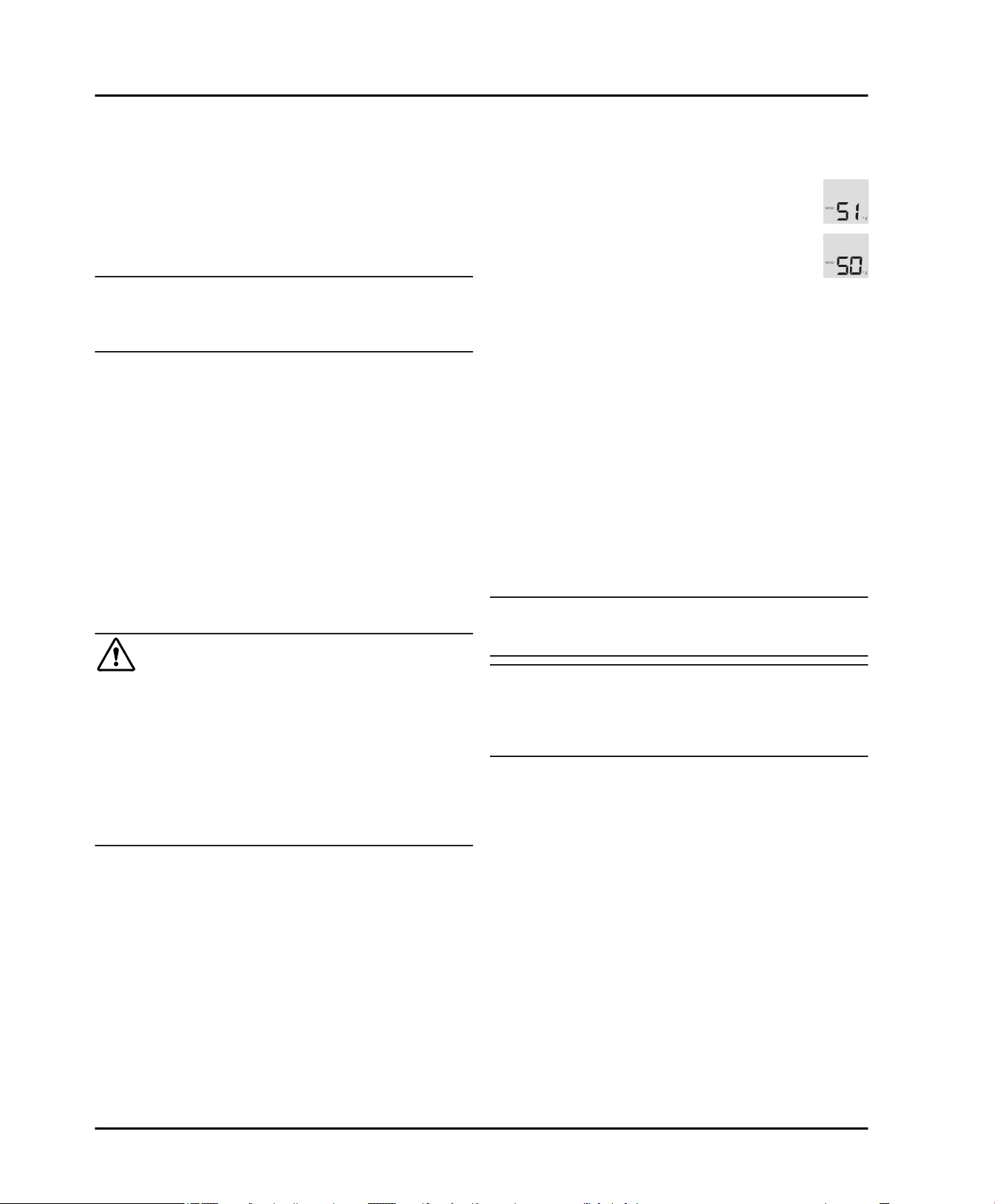
When S1 is shown on the display:
To turn on Sabbath mode, briefly press the
u
SuperFrost button
When S0 is shown on the display:
To turn off Sabbath mode, briefly press the
u
SuperFrost button
To deactivate setting mode: Press the Freezer
u
compartment On/Off button
-or-
Wait 5 min.
u
The Sabbath Mode symbol
w
temperature display as long as Sabbath Mode is active.
Sabbath mode switches off automatically after 120
w
hours if it is not manually switched off beforehand.
Fig. 4 (19)
Fig. 4 (14)
Fig. 4 (14)
lights up.
Fig. 4 (14)
.
.
Fig. 4 (13)
Fig. 4 (18)
.
.
appears on the
5.7 Fridge compartment
The natural circulation of air in the refrigerator compartment results in zones with differing temperatures. It is
coldest directly above the vegetable drawers and at the
rear wall. It is warmest at the top front of the compartment
and in the door.
5.7.1 Refrigerating food
Note
Do not load the door with more than 40 lbs (18 kg) of
u
food.
WARNING
Danger of food poisoning!
No record will be kept of a power failure during Sabbath
Mode. Thus, during Sabbath mode, if a power failure
occurs that you are not aware of, when the power comes
back on, the unit will continue to be in Sabbath Mode but
when Sabbath Mode is ended there will be no indication
that a power failure occurred.
If a power failure occurs during Sabbath mode:
Check the quality of the food. Do not consume spoiled
u
food!
No control operations are possible other than switching
off Sabbath Mode.
If the unit is currently running in a mode such as Super-
frost, Supercool or the Ventilation is enabled these
functions will continue and finish their timed cycles
independent of now being in Sabbath mode.
The Ice Maker is disabled.*
No audible signals are emitted, and the temperature
display does not indicate any warnings or settings
(such as a temperature alarm or door alarm).
Light does not operate.
-
5.6.1 Setting Sabbath mode
To activate setting mode: Press and hold the Super-
u
Frost button
Fig. 4 (14)
for approx. 5 s.
Note
Insufficient ventilation results in an increase in energy
consumption and reduction of the refrigerating performance.
Never block the air slits in the fan.
u
Use recyclable plastic, metal, aluminum and glass
u
containers and cling film to wrap foods.
Always use closed containers for liquids and for food
u
that may give off or be tainted by odor or flavor transfer
or cover them.
Foods which give off a large amount of ethylene gas
u
and those that are sensitive to this gas, such as fruit,
vegetables and salad, should always be separated or
wrapped so as not to reduce the storage life; for
example, do not store tomatoes together with kiwi fruits
or cabbage.
Do not store food too close together to enable sufficient
u
air circulation.
To ensure bottles do not tip over: move the bottle
u
holder.
5.7.2 Setting the temperature
The temperature depends on the following factors:
the number of times the door is opened
the room temperature of the installation location
-
* Depending on model and options 19
Operation
the type, temperature and amount of food.
The temperature can be set from 35 °F (2 °C) to 45 °F
(7 °C), 41 °F (5 °C) is recommended.
To set a higher temperature: press the Fridge compart-
u
ment Up button
To set a lower temperature: press the Fridge compart-
u
ment Down button
When pressed once the previously set fridge compart-
w
ment temperature display value will flash.
To change the temperature in 1 °F (1 °C) increments:
u
briefly press the button.
To change the temperature continuously: hold the
u
button down.
The value is displayed flashing during the setting oper-
w
ation.
The actual temperature is displayed about 5 seconds
w
after the last press of a button. The temperature slowly
adjusts to the new value.
5.7.3 SuperCool
With SuperCool you switch to the highest cooling
performance to reach lower cooling temperatures. Use SuperCool to rapidly cool large quantities of food.
If SuperCool is on, the fan* may come on. The appliance
works at maximum refrigerating power. The sound of the
refrigeration unit may be temporarily louder as a result.
SuperCool will use more energy than normal operation.
Fig. 4 (4)
Fig. 4 (5)
.
.
Switching on the fan
Briefly press Ventilation button
u
The Ventilation symbol
w
The fan is on. On some appliances it only switches on
w
when the compressor is running.
Switching the fan off (default)
Briefly press Ventilation button
u
The Ventilation symbol
w
The fan is switched off.
w
Fig. 4 (17)
Fig. 4 (17)
Fig. 4 (1)
Fig. 4 (1)
.
LED lights up.
.
LED goes out.
5.7.5 Shelves
Shifting or removing shelves
CAUTION
Danger of lacerations!
The storage shelf can shatter if dropped or mishandled.
You could cut yourself on the pieces of broken glass.
Only remove storage shelves when there is nothing on
u
them.
Extension stops secure the shelves against being accidentally pulled out.
Cooling with SuperCool
Briefly press the SuperCool button
u
The SuperCool symbol
w
display.
The cooling temperature drops to the coldest value.
w
SuperCool is switched on.
SuperCool automatically switches itself off after about
w
6-12 hours. The appliance returns to work in the
energy-saving normal mode.
To prematurely switch off SuperCool
Briefly press the SuperCool button
u
The SuperCool symbol
w
display.
SuperCool is switched off.
w
Fig. 4 (6)
Fig. 4 (6)
Fig. 4 (2)
LED lights up on the
Fig. 4 (2)
LED goes out on the
.
.
5.7.4 Fan
The fan allows you to rapidly cool large amounts
of fresh food or to achieve a relatively even
distribution of temperature across all the storage
levels.
Re-circulated air cooling is advisable:
at high room temperatures (from approx. 95 °F
(35 °C) )
in the case of high humidity
-
Re-circulated air cooling has a somewhat higher energy
consumption. To save energy, the fan automatically
switches off when the door is open.
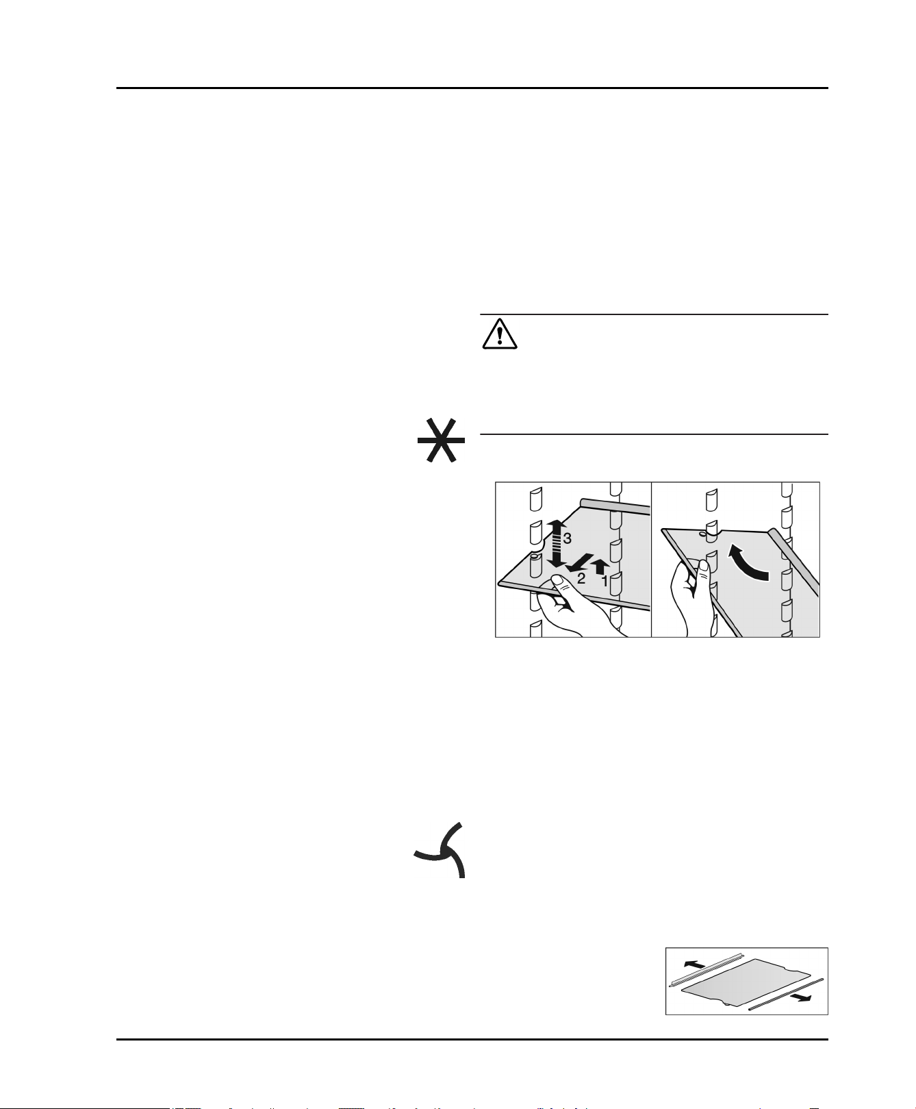
Fig. 42
Lift up the shelf and pull it slightly forward.
u
Adjust the shelf height by shifting the spacers in the
u
runners.
Insert the short shelf at the height of the gallon capacity
u
rack so that door closes properly. It is supported on
support bars.
To remove the shelf completely, set it at an angle and
u
pull it out towards you.
Insert the shelf with the raised edge to the back
u
pointing upwards.
This prevents food from contacting and freezing to the
w
back wall.
The bottle holder offers additional storage for bottles
(maximum height 11-13/16 '' (300 mm)). It fits onto the
same supports as the other racks.
Insert the bottle holder into any position, but not right at
u
the bottom.
To dismantle shelves
The shelves can be
u
dismantled for cleaning.
20 * Depending on model and options
Operation
5.7.6 Using the split shelf
CAUTION
Danger of lacerations!
The storage shelf can shatter if dropped or mishandled.
You could cut yourself on the pieces of broken glass.
Only remove storage shelves when there is nothing on
u
them.
Fig. 43
Attach support bars supplied, ensuring right (R) and left
u
(L) parts are correctly positioned.
The glass shelf with stop face (2) has to be at the back.
u
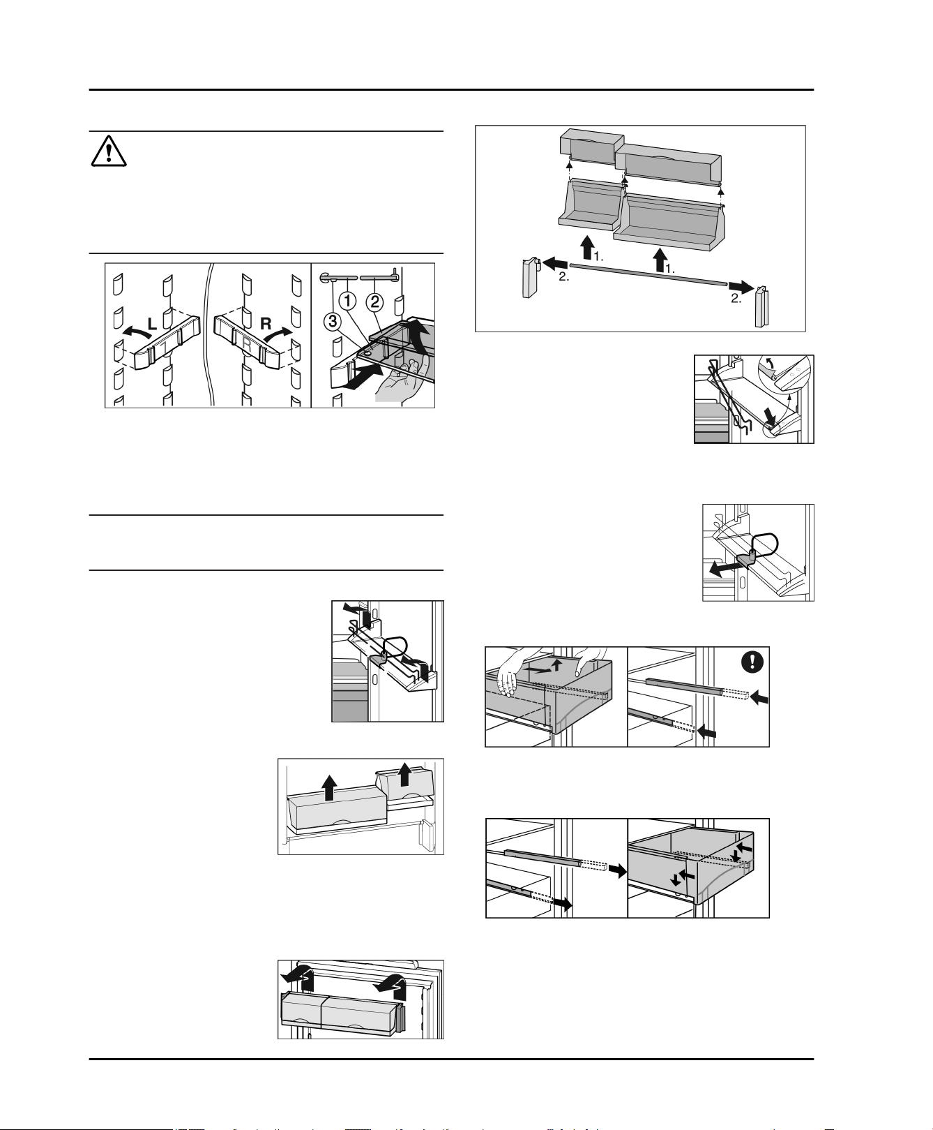
5.7.7 Door racks
Note
Do not load the door with more than 40 lbs (18 kg) of
u
food.
To dismantle door racks
Fig. 44
The door racks can be dismantled for cleaning.
u
5.7.8 Removing the bottle holder
Always take hold of the bottle
u
holder by the plastic part.
Repositioning the door racks
Push rack up, pull forward, and reinsert in the reverse
u
order.
The container trays can be
removed and placed on the
table as a unit.
Instead of one wide container and one small container, a
special set containing three small containers is available
from Customer Service.
It is possible to use one or both boxes. If unusually tall
bottles are to be stored, only suspend one box above the
bottle rack.
To swap containers: pull
u
up to remove and reinsert
in the desired position.
5.7.9 Vegetable drawers
To remove the vegetable drawers:
Pull the vegetable drawer completely out and tilt it
u
slightly forward.
Push the protruding telescopic rails back in.
u
To insert the vegetable drawers:
Place the vegetable drawer on the telescopic rails and
u
slide it back while applying light pressure.
Fig. 45
Fig. 46
* Depending on model and options 21
Operation
5.8 Freezer compartment
You can store frozen food, make ice cubes and freeze
fresh food in the freezer compartment.
5.8.1 Freezing food
The actual temperature is displayed about 5 seconds
w
after the last press of a button. The temperature slowly
adjusts to the new setting.
5.8.4 SuperFrost
Each drawer can hold up to 55.12 lbs (25 kg) of frozen
food; each plate can hold up to 77.16 lbs (35 kg).
CAUTION
There is a risk of injury from pieces of broken glass.
Bottles and cans containing drinks can split or crack when
frozen. This applies in particular to carbonated drinks.
Do not freeze bottles and cans containing drinks.
u
So that the food is rapidly frozen through to the core, do
not exceed the following quantities per pack:
- fruit, vegetables up to 2.2 lb (1 kg)
- meat up to 5.51 lbs (2.5 kg)
Pack the food in portions in freezer bags, reusable
u
plastic, metal or aluminum containers.
5.8.2 Defrosting food
- in the fridge compartment
- in the microwave
- in the oven/fan oven
- at room temperature
WARNING
Danger of food poisoning!
Do not re-freeze defrosted food.
u
Only take out the amount of food that is required. Use
u
defrosted food as quickly as possible.
5.8.3 Setting the temperature in the freezer
compartment
The appliance is set as standard for normal operation.
The temperature can be set between 7 °F (-14 °C) and
-16 °F (-26 °C), 0 °F (-18 °C) is recommended.
To set a higher temperature: press the Freezer
u
compartment Up button
To set a lower temperature: press the Freezer compart-
u
ment Down button
When the button is pressed for the first time, the
w
previous value is indicated on the freezer compartment
temperature display.
To change the temperature in 1 °F (1 °C) increments:
u
briefly press the button.
-or-
To change the temperature continuously: hold the
u
button down.
The value is displayed flashing during the setting oper-
w
ation.
Fig. 4 (11)
Fig. 4 (12)
.
.
Depending on how much fresh food is to be frozen you
must switch SuperFrost on in advance - for a small
amount of food to be frozen, about 6 hours, for the
maximum amount about 24 hours before putting the food
in.
You do not need to switch SuperFrost on in the following
cases:
when placing frozen food in the freezer
when freezing up to about 2 kg of fresh food a day
-
Freezing with SuperFrost
Briefly press the SuperFrost button
u
The SuperFrost symbol
w
The freezing temperature drops and the appliance
w
operates at its maximum refrigeration power rating.
When a small amount of food is to be frozen.
Wait approx. 6 hrs.
u
Place packaged food in the upper drawers.
u
When the maximum amount of food is to be frozen.
Wait approx. 24 hrs.
u
Remove upper drawers and place the food directly
u
onto the upper shelves.
SuperFrost is automatically switched off. At the earliest
w
after 30 hours, at the latest after 65 hours, depending
on the quantity placed inside the appliance.
The LED for the SuperFrost symbol
w
when the freezing process is complete.
Place food inside the drawers and push them closed
u
again.
The appliance returns to work in the energy-saving
w
normal mode.
Fig. 4 (21)
Fig. 4 (14)
LED lights up.
Fig. 4 (21)
once.
goes out
5.8.5 Drawers
Note
Insufficient ventilation results in an increase in energy
consumption and reduction of the refrigerating performance.
For appliances with NoFrost:
Leave the bottom drawer in the appliance.
u
Never block the air slits in the fan on the rear wall.
u
To store frozen food directly on the shelves: pull the
u
drawer forward and lift it out.
22 * Depending on model and options
Operation
5.8.6 Shelves
To remove shelf: lift it at the front and
u
pull out forward.
To reinsert shelf: simply slide it in as
u
far as it will go.
5.8.7 VarioSpace
In addition to the drawers, you
can also take out the shelves.
This gives you space for large
frozen items. Poultry, meat, large
joints of game and tall bakery
items can be frozen and then
presented whole.
Each drawer can hold up to
u
55.12 lbs (25 kg) of frozen
food; each plate can hold up to
77.16 lbs (35 kg).
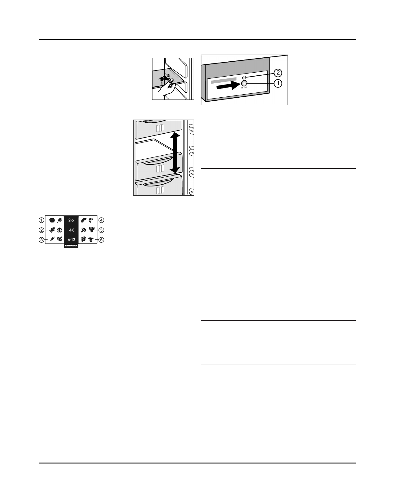
5.8.8 Info system
Fig. 47
(1) Ready meals, ice
cream
(2) Pork, fish (5) Game, mushrooms
(3) Fruit, vegetables (6) Poultry, beef/veal
The numbers indicate the storage time in months for
different types of frozen foods. The storage times given
are guidelines.
(4) Sausages, bread
5.8.9 IceMaker*
The IceMaker is in the top drawer. The drawer is labeled
“IceMaker”.
Make sure that the following conditions are fulfilled:
The appliance is level.
The appliance is connected to the electricity supply.
The freezer compartment is switched on.
The minimum freezer temperature is 14 °F (-10 °C).
The IceMaker is connected to the water supply.
All air was bled from the waterline before starting the
icemaker. The icemaker will only work if there is no air
in the waterline.
Switching on the IceMaker*
Fig. 48
Pull out the drawer.
u
Press On/Off button
u
lights up.
Push in the drawer.
u
The IceMaker symbol
w
Note
The IceMaker only produces ice cubes when the
u
drawer is completely closed.
Producing ice cubes*
The production capacity depends on the freezer temperature. The lower the temperature, the more ice cubes can
be produced in a certain period.
The production capacity is 90- 100 ice cubes in 24 hours
at a freezing temperature of 0 °F (-18 °C).
To have the maximum capacity of approx. 130 ice cubes
in 24 hours, activate the SuperFrost Function. Be aware
that this increases the energy consumption because the
compressor will run constantly.
The ice cubes fall out of the IceMaker into the drawer.
When the ice cubes reach a certain height in the drawer,
no more ice cubes can be produced. The IceMaker will
not fill the drawer to the top.
If large quantities of ice cubes are required, the complete
IceMaker drawer can be swapped with the neighboring
drawer. When you close the drawer, the IceMaker automatically restarts production.
When the IceMaker is switched on for the first time, it may
take up to 24 hours for the first ice cubes to be produced.
Note
Particles may accumulate in the IceMaker or water line
the first time the appliance is used or after an extended
period out of service.
To achieve this, do not consume or use the ice cubes
u
that are produced within 72 hours.
Setting the water supply time*
The opening time of the valve on the IceMaker can be
adjusted if, for example, the water pressure in the pipe is
too low or too high.
The water supply time can be set in stages from E1 (short
supply time) to E8 (long supply time). The default setting
is E3.
Activate setting mode: press and hold the SuperFrost
u
Fig. 4 (14)
button
w
S is shown on the display.
The Menu symbol
w
Fig. 48 (1)
Fig. 4 (10)
for approximately 5 s.
Fig. 4 (19)
so that the LED
LED lights up.
lights up.
Fig. 48 (2)
* Depending on model and options 23

Maintenance
Using the Freezer compartment Up button
u
Freezer compartment Down button
To confirm: briefly press the SuperFrost button
u
Fig. 4 (14)
To increase the water supply time: press the
u
Freezer compartment Up button
To decrease the water supply time: press the
u
Freezer compartment Down button
To confirm: press the SuperFrost button
u
Fig. 4 (14)
Deactivate setting mode: press the Freezer compart-
u
ment On/Off button
-or-
Wait 5 mins.
u
The temperature is again displayed on the temperature
w
display.
Switching off the IceMaker*
If ice cubes are not required, the IceMaker can be
switched off independently of the freezer compartment.
When the IceMaker is switched off, the drawer of the
IceMaker can also be used for freezing and storing food.
Press the On/Off button for about 1 second until the
u
LED goes out.
The IceMaker symbol
w
Clean the IceMaker.
u
This ensures that no water or ice remains in the
w
IceMaker.
.
.
Fig. 4 (13)
Fig. 4 (10)
Fig. 4 (12)
Fig. 4 (11)
Fig. 4 (12)
.
LED goes out.
Fig. 4 (11)
, select E.
.
.
or
Fig. 50
To install a new water filter:
Insert the water filter
u
100° clockwise until it locks into position.
Slide the tray
u
Place the cover
u
Write the date of the next filter replacement on the
u
supplied adhesive label
module.
Note
New water filters may contain particulate matter.
Do not consume or use ice cubes produced within 72
u
hours after replacing the filter.
Remove any ice still present in the IceMaker tray. You
u
can keep this ice in another tray for later use.
Make sure the filter is leak-tight and no water is coming
u
out.
Fig. 50 (1)
Fig. 50 (3)
in.
Fig. 50 (2)
and turn it approximately
on the filter.
Fig. 50 (4)
and affix it to the
6.2 Defrosting with NoFrost
6 Maintenance
6.1 Replacing the water filter*
When used as indicated, the water filter should be
replaced at least every 6 months or whenever you notice
a considerable decrease in the flow rate.
Your nearest dealer can be located by visiting us online at
www.Liebherr.com.
The used water filter contains activated carbon and can
be disposed of with normal household waste.
Fig. 49
To remove the old water filter:
Pull out the tray
u
Remove the filter cover
u
Turn the water filter
u
terclockwise and pull it out.
Catch any dripping water with your hand, towel or with
u
a dish.
Fig. 49 (1)
Fig. 49 (2)
Fig. 49 (3)
, if necessary.
.
approximately 100° coun-
The NoFrost system defrosts the appliance automatically.
Fridge compartment:
The defrosted water is evaporated by the heat of the
compressor. Drops of water on the back wall are a functional feature and completely normal.
Clean the drain opening regularly so that the defrosted
u
water can flow away (see 6.3) .
Freezer compartment:
The moisture condenses on the evaporator and is periodically defrosted and evaporated.
The appliance does not need to be defrosted manually.
u
6.3 Cleaning the appliance
WARNING
Danger of electric shock.
Unplug refrigerator or disconnect power.
u
WARNING
Risk of injury or damage due to hot steam.
Hot steam can cause scalding/burns and damage to
surfaces.
Do not use steam cleaners.
u
24 * Depending on model and options
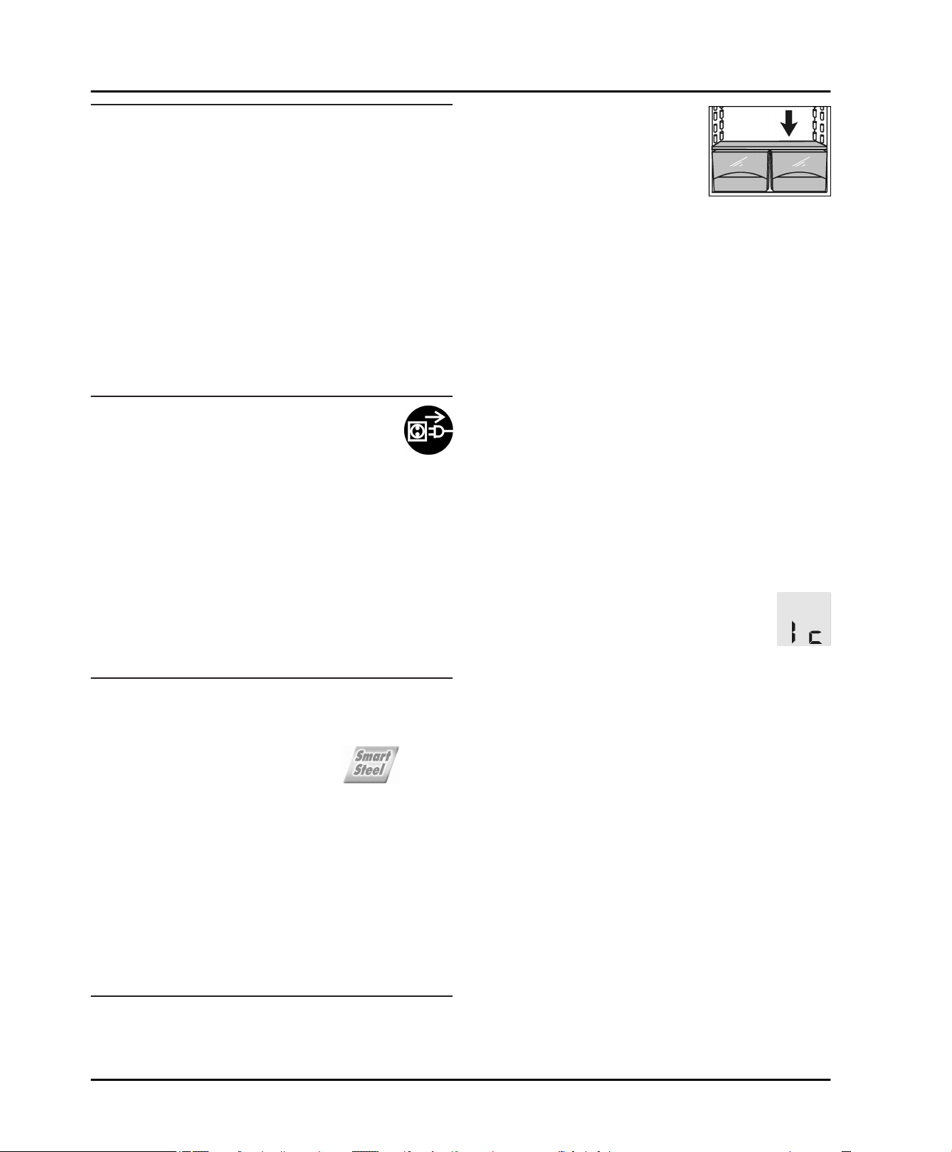
NOTICE
Incorrect cleaning damages the appliance.
Do not use concentrated cleaning agents.
u
Do not use steel wool or sponges that scour or scratch.
u
Do not use caustic or abrasive cleaning materials or
u
those containing sand, chloride, chemicals or acids.
Do not use chemical solvents.
u
Do not damage or remove the rating plate on the inside
u
of the appliance. It is vital for the customer service
department.
Do not pull off, kink or damage any cables or other
u
components.
Do not let cleaning water get into the drain gutter, the
u
ventilation grille and electrical parts.
Use soft cleaning cloths and a multi-purpose cleaning
u
agent with a neutral pH value.
Only use food-compatible cleaning and care agents
u
inside the appliance.
Empty the appliance.
u
Disconnect the power plug.
u
Maintenance
To clean the drain opening:
u
Remove deposits with a thin
instrument, e.g. a cotton bud.
Most of the equipment parts can be dismantled for
u
cleaning: see the respective chapter.
Clean fittings by hand using lukewarm water and a
u
little dish washing liquid.
Clean the telescopic rails with a damp cloth only. The
u
grease in the tracks is for lubrication purposes and
should not be removed.
After cleaning:
Wipe the appliance and accessories dry.
u
Connect the appliance and switch it on again.
u
Switch on SuperFrost (see 5.8.4) .
u
When the temperature is sufficiently cold:
put the food back in the appliance.
u
6.4 Cleaning the IceMaker*
Clean the plastic surfaces, outside and inside, by
u
hand using lukewarm water and a little dish washing
liquid.
Stainless steel which is exposed to chlorine gas or dampness may become discolored. This is normal. If your
appliance is exposed to chlorine gas or dampness, clean
and polish it more frequently. If there are any signs of rust
or discoloration, clean and polish the appliance as soon
as possible.
Do not apply stainless steel cleaning agents to glass or
plastic surfaces so as not to scratch them. Initially darker
areas and quite an intensive color of the stainless steel
surfaces are normal.
NOTICE
The stainless steel doors are treated with a high-grade
surface coating and must not be cleaned with the
supplied cleaning agent.
This would damage the surface coating.
Wipe the coated door surfaces using a soft, clean
u
cloth only. In case of stubborn dirt, use a little water or a
neutral cleaning agent. A microfibre cloth can be
optionally used.
If the stainless steel side walls are dirty, clean them
u
using a commercially available stainless steel cleaning
agent. Then evenly apply the accompanying stainless
steel care product, making strokes in the direction of
the grain.
Wipe side walls with a paint finish using a soft, clean
u
cloth only. In case of stubborn dirt, use a little water or a
neutral cleaning agent. A microfibre cloth can be
optionally used.
The IceMaker drawer must be emptied and pushed in.
Activate setting mode: press and hold the SuperFrost
u
button
Fig. 4 (14)
w
S is shown on the display.
The Menu symbol
w
Using the Freezer compartment Up button
u
Freezer compartment Down button
To confirm: press the SuperFrost button
u
Using the Freezer compartment Up button
u
Fig. 4 (11)
Fig. 4 (12)
To confirm: press the SuperFrost button
u
Fig. 4 (14)
The IceMaker moves into cleaning position and shuts
w
off.
Deactivate setting mode: press the Freezer compart-
u
ment On/Off button
-or-
Wait 2 min.
u
The temperature is again displayed on the temperature
w
display.
Take out the drawer.
u
Clean the ice compartment and drawer with warm
u
water. If necessary, use a mild dishwashing liquid.
Then rinse.
Slide the drawer back in.
u
If dishwashing liquid was used:
Throw out the first three batches of ice cubes to get rid
u
of any dishwashing liquid residues.
Either leave the IceMaker switched off in this position or
switch the IceMaker back on (see 5.8.9) .
/ Freezer compartment Down button
, select Ic.
.
for approximately 5 s.
Fig. 4 (19)
Fig. 4 (13)
lights up.
Fig. 4 (12)
.
Fig. 4 (11)
, select I.
Fig. 4 (14)
.
6.5 Customer service
/
First check whether you can remedy the fault yourself
(see Troubleshooting). If this is not the case, please
contact a qualified service provider.
* Depending on model and options 25
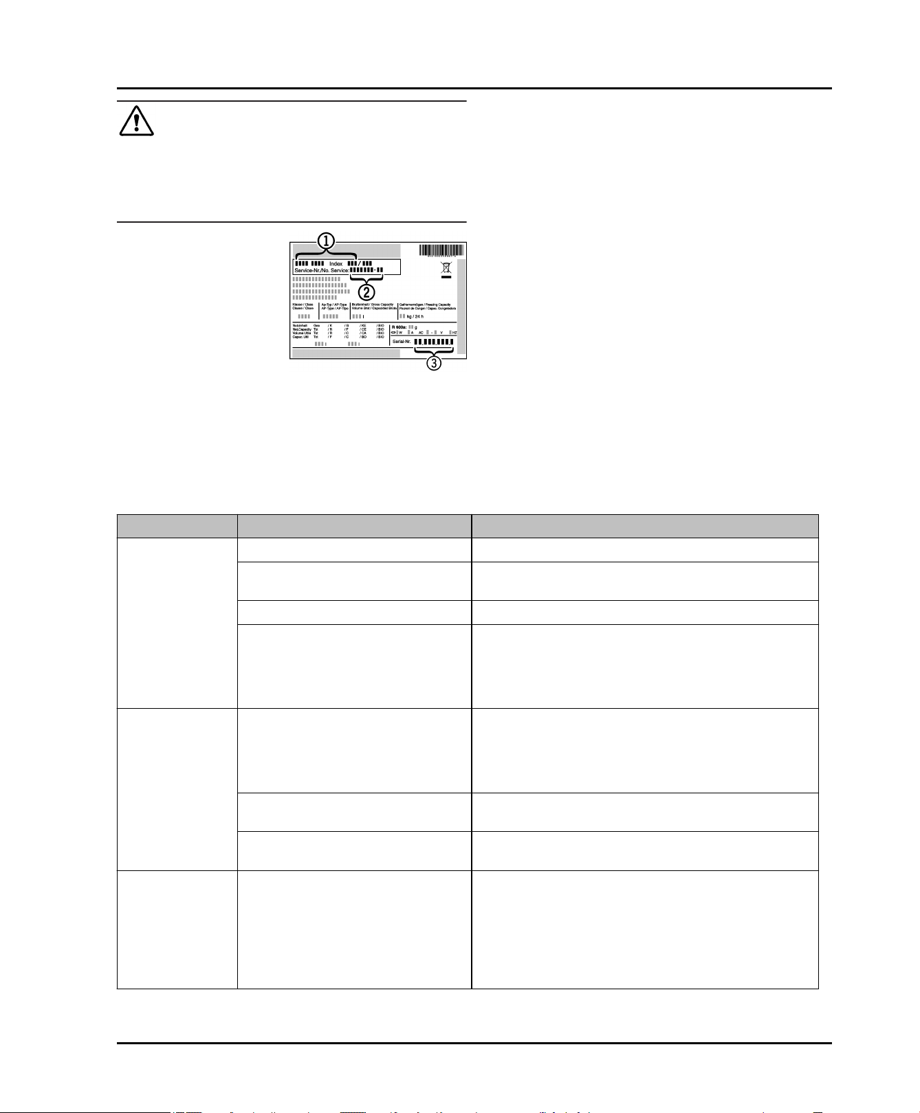
Troubleshooting
WARNING
Risk of injury from repairs by non-professionals.
Repairs and work on the appliance and the power
u
supply cable not described in the Manual (see Maintenance) should only be carried out by a qualified service
provider.
Read the appliance
u
designation
Fig. 51 (1)
Fig. 51 (2)
no.
the rating plate. The
rating plate is located
inside the appliance
on the left-hand side.
Notify a qualified service provider, specifying the fault,
u
appliance designation
and serial
This will help us to provide you with a faster and more
w
accurate service.
Keep the appliance closed until the Customer Service
u
engineer arrives.
, service no.
and serial
Fig. 51 (3)
Fig. 51 (3)
from
no.
Fig. 51 (1)
, service no.
Fig. 51 (2)
Fig. 51
The food will stay cool longer.
w
Disconnect the power plug (do not pull on the power
u
cord to do this) or switch off the fuse.
6.6 Appliance Information
Make a note of this information when the appliance is
installed:
Type Designation: _____________________
Service Number: _____________________
Appliance / Serial Number: _____________________
Date of purchase: _____________________
Where purchased: _____________________
7 Troubleshooting
Your appliance is designed and manufactured for reliable
operation and a long lifespan. If a malfunction nonetheless occurs during operation, please determine if the
malfunction is due to an operating error. If a service call
determines operator error, you will be charged for the
costs incurred, even during the warranty period. You may
be able to rectify the following problems yourself:
Problem Possible Cause Correction
The appliance
does not work.
The compressor
runs for a long
time.
A LED at the
lower rear of the
appliance (for
the compressor)
flashes regularly
every 15
seconds*.
The appliance is not switched on.
The power plug is not properly
inserted in the wall socket.
The fuse in the wall socket is not OK.
Power failure
When less refrigeration is required,
the speed-controlled compressor
switches to a low speed. Although
the running time is increased as a
result, energy is saved.
SuperFrost function is activated.
SuperCool function is activated.
The inverter is equipped wth a diagnostic LED.
Switch on the appliance.
u
Check the power plug.
u
Check the fuse.
u
Keep the appliance closed.
u
Protect the food: place dry ice on top of the food or
u
use an alternate freezer, if the power failure persists
for some time.
Do not re-freeze defrosted food.
u
This is normal in energy-saving models.
u
The compressor runs long to rapidly freeze food.
u
This is normal.
The compressor runs long to rapidly cool food. This
u
is normal.
The flashing is normal.
u
26 * Depending on model and options
Problem Possible Cause Correction
Troubleshooting
Noises are too
loud.
A gurgling
sound
A faint clicking
sound
A hum. It is
briefly a little
louder when the
refrigeration unit
(the motor)
switches on.
A low hum
The different speed levels of speedcontrolled* compressors can cause
them to generate various noises
during operation.
This sound comes from the refrigerant flowing in the refrigeration
circuit.
The sound always occurs when the
refrigeration unit (the motor) automatically switches on or off.
The refrigeration increases automatically when the SuperFrost function is
activated, fresh food has just been
placed in the appliance or the door
has been left open for a while.
The refrigeration increases automatically when the SuperCool function is
activated, fresh food has just been
placed in the appliance or the door
has been left open for a while.
The ambient temperature is too high.
The sound occurs as a result of fan
air flow.
These noises are normal.
u
The sound is normal.
u
The sound is normal.
u
The sound is normal.
u
The sound is normal.
u
Solution: (see 1.3)
u
The sound is normal.
u
Vibration noise
The temperature
display indi-
cates: F0 to F9.
The temperature
display reads:
FE*
The temperature
display shows a
flashing power
failure symbol
. The
warmest temperature reached
during the
power failure is
displayed in the
temperature
display.
DEMO lights up
in the temperature display.
The appliance is not standing firmly
on the floor As a result, adjoining
units or objects are set into vibration
by the running refrigeration unit
There is a fault.
There is a fault.
The freezer temperature rose too
high during the last hours or days
due to power failure or power interruption. When the power interruption
is over, the appliance will continue to
operate at the last temperature
setting.
The demo mode is activated.
Align the appliance using the adjustable feet
u
Move bottles and containers apart.
u
Contact the customer service department (see Main-
u
tenance).
Contact the customer service department (see Main-
u
tenance).
To delete the display of the warmest temperature:
u
Press the Alarm button
Check the quality of the food. Do not consume
u
spoiled food. Do not re-freeze defrosted food.
Contact the customer service department (see Main-
u
tenance).
Fig. 4 (15)
.
* Depending on model and options 27
Troubleshooting
Problem Possible Cause Correction
The outside
surfaces of the
appliance are
hot*.
The IceMaker
cannot be
switched on.*
The IceMaker is
not making ice
cubes.*
The temperature
is not cold
enough.
The heat of the refrigerant circuit is
used to prevent condensate from
forming.
The appliance and therefore the
IceMaker are not connected.
The IceMaker is not switched on.
The drawer of the IceMaker is not
properly closed.
The water connection is not open.
The water supply to the IceMaker
was interrupted.
There is a blocked filter at the end of
the water supply hose or at the
connecting part on the machine.
The waterline was not bled of all air
during installation
The door of the appliance is not
closed properly.
Insufficient ventilation.
The ambient temperature is too high.
The appliance was opened too
frequently or for too long.
This is normal.
u
Connect the appliance (see Start-up).
u
Switch the IceMaker on.
u
Close the drawer properly.
u
Open the water connection.
u
Check the connection to the water supply (see Start-
u
up).*
Check the pipes and hoses (see Start-up).*
u
Clean the filters.
u
Please contact your qualified installation plumber to
u
ensure the above criteria is met before calling for
service.
Close the appliance door.
u
Clear ventilation grilles.
u
Solution: (see 1.3)
u
Wait to see whether the required temperature resets
u
itself by itself. If not, contact the customer service
department (see Maintenance).
Too much fresh food was placed
inside without SuperFrost.
The temperature is incorrectly set.
The appliance is too near to a heat
source (stove, heater etc).
Display show
two dashes (“-
-”).
The interior light
is not on.
28 * Depending on model and options
The freezer temperature display will
only show temperatures that are
below freezing.
The freezer temperature has risen
above zero degrees due to a power
failure or power interruption.
The appliance is not switched on.
The door was open for longer than
15 minutes.
Solution: (see 5.8.4)
u
Set to a colder temperature and check after 24 hours
u
Change location of appliance or the heat source.
u
When initially starting the appliance it will not be
u
below freezing. It will take three to five hours
(depending on ambient conditions) for freezing
temperatures to be achieved and thus displayed
numerically.
u
See also “Power failure” and “
Switch on the appliance.
u
The interior light automatically switches itself off if
u
the door has been open for about 15 minutes.
”
Putting appliance out of service
Problem Possible Cause Correction
The LED interior light is faulty or the
cover is damaged
Risk of injury from electrical shock.
Live parts are under the cover.
u
Risk of injury from LED lamp!
The lighting intensity of the LED light complies with laser
class 1/1M.
If the cover is faulty:
u
WARNING
The LED interior light should only be replaced or
repaired by the Customer Service department or by
engineers trained to do so.
WARNING
Do not gaze directly at this lighting unit with optical
lenses while very close to the light source. This can
cause damage to your eyes.
8 Putting appliance out of service
8.1 Vacation Tips
Short vacations: If you will be away for less than four
weeks
Use all perishables.
u
Freeze other items.
u
Turn off the refrigerator compartment.
u
Turn off the icemaker.*
u
Shut down the water supply to the icemaker.*
u
Long vacations: If you will be away for a month or more
Remove all food from the appliance.
u
Turn OFF the appliance.
u
Clean the appliance (see 6.3) .
u
Leave the door open to prevent unpleasant odors.
u
This will also keep mold from building up.
w
Turn off the icemaker.*
u
Shut off the water supply to the icemaker.*
u
8.2 Switching off the appliance
Note
To switch off the entire appliance, only the freezer
u
compartment needs to be switched off.
8.2.1 Switching off the freezer compartment
Press and hold down the freezer compart-
u
ment On/Off button
seconds.
The temperature displays are dark. The
w
appliance is switched off.
Fig. 4 (13)
for approx. 2
8.2.2 Switching off the fridge compartment
Press and hold down the chiller compartment On/Off
u
button
Fig. 4 (3)
The fridge compartment temperature display
w
dark. The fridge compartment is switched off.
for approx. 2 seconds.
Fig. 4 (8)
is
8.3 Decommissioning *
Empty the appliance.
u
Put the IceMaker in the cleaning position (see Mainte-
u
nance).
Disconnect the power plug.
u
Clean the appliance (see 6.3) .
u
Leave the door open to prevent bad smells.
u
9 Disposing of the appliance
Follow the local regulations for the disposal of appliances.
Old appliances can be dangerous. Contact the local
refuse collection department for additional information.
DANGER
There is a risk of suffocation.
Children playing can shut themselves in and suffocate.
Take the door(s) off.
u
Remove the drawers.
u
Leave the storage shelves in the appliance so that chil-
u
dren cannot easily climb into the appliance.
* Depending on model and options 29
Liebherr Warranty Plan
WARNING
Danger of electric shock.
Cut off the plug from the power cord and discard.
u
Cut off the power cord from the discarded appliance.
u
Dispose of separately from the appliance.
Ensure during and after disposal that the appliance isn't
stored in the vicinity of gasoline or other flammable vapors
and liquids.
When disposing of the appliance, ensure that the refriger-
ation circuit is not damaged to prevent uncontrolled
escape of the refrigerant it contains (data on type plate)
and oil.
10 Liebherr Warranty Plan
FULL TWO YEAR WARRANTY - For two years from the
date of original purchase, your Liebherr warranty covers
all parts and labor to repair or replace any part of the
product which proves to be defective in materials or work-
manship.
FULL FIVE YEAR WARRANTY - For five years from the
date of original purchase, your Liebherr warranty covers
all parts and labor to repair or replace any components
that prove to be defective in materials or workmanship in
the sealed system. The “Sealed System” means only the
compressor, condenser, evaporator, drier and all
connecting tubing.
LIMITED 6TH THROUGH 12TH YEAR WARRANTY -
From the 6th through 12th year from the date of original
purchase, your Liebherr warranty covers all parts that
prove to be defective in materials or workmanship in the
Sealed System (parts only).
TERMS APPLICABLE TO EACH WARRANTY
All service provided by Liebherr under the warranty must
be performed by authorized Liebherr service representa-
tives, unless otherwise specified by Liebherr. Service will
be provided in the home during normal business hours.
This warranty applies only to products installed for normal
residential use. Details regarding a non-residential
warranty are available on request.
The warranty applies only to products installed in any one
of the fifty states of the United States or the District of
Columbia. The warranty does not cover any parts or labor
to correct any defect caused by negligence, accident or
improper use, maintenance, installation, service or repair,
including but not limited to improper removal and reinstal-
lation of the condensing unit.
THE WARRANTIES DESCRIBED ABOVE ARE MADE
EXPRESSLY IN LIEU OF ANY OTHER WARRANTIES,
EXPRESSED OR IMPLIED, INCLUDING ANY IMPLIED
WARRANTY OF MERCHANTABILITY OR FITNESS
FOR A PARTICULAR PURPOSE, AND OF ANY OTHER
OBLIGATION OR LIABILITY ON THE PART OF LIEB-
HERR. IN NO EVENT SHALL LIEBHERR BE LIABLE
FOR SPECIAL, INCIDENTAL OR CONSEQUENTIAL
DAMAGES ARISING FROM THE BREACH OF THESE
WARRANTIES OR ANY OTHER WARRANTIES,
WHETHER EXPRESS, IMPLIED OR STATUTORY.
Some states do not allow the exclusion or limitation of
incidental or consequential damages so the above limitation or exclusion may not apply to you. This warranty
gives you specific legal rights and you may also have
other legal rights which very from state to state.
To receive parts and/or service and the name of the Liebherr authorized service representative nearest you,
contact your Liebherr dealer or distributor or contact the
Liebherr designated national service provider:
in the US: Service-appliances.us@liebherr.com or call
1-866-LIEBHER (1-866-543-2437).
in Canada: www.euro-parts.ca or call 1-888-LIEBHER
(1-888-543-2437).
30 * Depending on model and options

Mode
d'emploi
Combiné réfrigérateur-
congélateur, pose libre
CS 1311 / CS 1360
260514 7085514 - 00

Vue d'ensemble de l'appareil
Sommaire
1 Vue d'ensemble de l'appareil....................... 32
1.1 Avantages supplémentaires............................. 32
1.2 Description de l'appareil et de son équipement 33
1.3 Domaine d'utilisation de l'appareil.................... 33
1.4 Conformité....................................................... 34
1.5 Dimensions hors tout de l'appareil................... 34
1.6 Economiser l'énergie........................................ 34
1.7 Exemple de rangement.................................... 34
2 Consignes de sécurité générales................ 34
3 Eléments de commande et d'affichage....... 36
3.1 Éléments de commande et de contrôle............ 36
3.2 Affichage de la température............................. 36
4 Mise en service.............................................. 36
4.1 Transport de l'appareil...................................... 36
4.2 Mise en place de l'appareil............................... 36
4.3 Inverser le sens de butée de porte................... 37
4.4 Montage du combiné Side-by-Side.................. 42
4.5 Prise d'eau....................................................... 45
4.6 Insertion entre deux éléments de cuisine......... 46
4.7 Sécurité anti-basculement................................ 46
4.8 Installer le filtre à eau........................................ 47
4.9 Eliminer l'emballage......................................... 48
4.10 Brancher l'appareil........................................... 49
4.11 Enclencher l'appareil........................................ 49
5 Commande..................................................... 49
5.1 Unité d’affichage de la température.................. 49
5.2 Luminosité de l'affichage de température......... 50
5.3 Verrouillage enfants......................................... 50
5.4 Alarme porte ouverte........................................ 50
5.5 Alarme de température..................................... 50
5.6 Mode Sabbath.................................................. 51
5.7 Réfrigérateur ................................................... 51
5.8 Compartiment congélateur............................... 54
6 Entretien......................................................... 56
6.1 Remplacement du filtre à eau........................... 56
6.2 Dégivrer avec le mode NoFrost........................ 57
6.3 Nettoyage de l'appareil..................................... 57
6.4 Nettoyer l'IceMaker.......................................... 58
6.5 S.A.V. .............................................................. 58
6.6 Informations sur l'appareil................................ 58
7 Dysfonctionnements..................................... 58
8 Mise hors service........................................... 62
8.1 Astuces pour les départs en vacances............. 62
8.2 Couper l'appareil.............................................. 62
8.3 Mise hors service............................................. 62
9 Elimination de l'appareil............................... 62
10 GARANTIE Liebherr....................................... 63
Vous avez fait l’acquisition d’un nouvel appareil et nous
vous en félicitons. Avec l’achat d’un tel appareil vous
disposerez de tous les avantages d’une technique du
froid des plus modernes et assurant une qualité au plus
haut niveau, une grande longévité et une sécurité parfaite
de fonctionnement.
Les équipements de votre appareil facilitent une utilisation
quotidienne très confortable.
Avec l’acquisition de cet appareil, fabriqué dans le
respect de l’environnement et utilisant des matériaux de
recyclage, vous participez activement avec nous à la
protection de l’environnement.
Nous espérons que votre nouvel appareil vous donnera
entière satisfaction.
Le fabricant travaille constamment au développement de
tous les types et modèles d'appareils.C'est pourquoi nous
nous réservons le droit de modifier la forme, l'équipement
et la technique de nos appareils. Nous vous remercions
de votre compréhension.
Afin de découvrir tous les avantages de votre nouvel
appareil, nous vous prions de lire attentivement ces
instructions de montage.
Ces instructions de montage sont valables pour plusieurs
modèles, des différences sont donc possibles.Les paragraphes ne concernant que certains appareils sont indiqués par un astérisque (*).
Les instructions de manipulation sont indiqués par
un , les résultats de manipulation par un .
1 Vue d'ensemble de l'appareil
1.1 Avantages supplémentaires
sans HCFC
Circuit réfrigérant avec optimisation des dépenses
d’énergie
Isolation efficace réductrice de la consommation
d’énergie
Faible consommation d’énergie
Des éléments électroniques faciles d’utilisation
Les fonctions activées sont affichées sur l’écran
La température peut être commandée à l’intérieur de la
classe climatique indépendamment de la température
de la pièce. Vous pouvez opter pour un affichage de la
température en °F ou en °C.
L’appareil dégivre automatiquement - le temps de dégi-
vrage manuel est supprimé.
Grand pouvoir net de refroidissement
Surfaces de rangement en verre de sécurité
Balconnets de contre-porte pratiques pour grandes
bouteilles
Grand pouvoir net de congélation
Surfaces de rangement pouvant être ôtées pour faire
de la place à des volumes importants de denrées.
Alarme en cas d’élévation de la température de congé-
lation
Les denrées fraîches peuvent être, selon les besoins,
congelées rapidement
Affichage de la température de congélation
En cas de panne secteur affichage « frost-control »
Tous les tiroirs sont appropriés pour une congélation
rapide
Eclairage intérieur LED clair
-
32 * selon le modèle et l‘équipement

Vue d'ensemble de l'appareil
Alarme sonore en cas d’ouverture de porte
Poignées de transport pour tous les gros tiroirs
Poignées de transport intégrées sur le corps de l’appa-
reil
Roulettes de transport sur la partie arrière
Facile à nettoyer
Butée de porte pouvant être changée
Cet appareil est certifié conforme aux
normes de l’organisation Star-K pour le
sabbat. Il peut donc être utilisé durant
les fêtes religieuses. Pour plus d’informations, veuillez consulter le site Star-K
sur Internet : www.star-k.org.
1.2 Description de l'appareil et de son
équipement
Fig. 1
(1) Poignées de trans-
port à l'arrière
(2) Éléments de
commande et de
contrôle
(3) Ventilateur (13)Zone la plus froide
(4) Balconnets comparti-
ment beurre-oeufs
(11)Eclairage intérieur
(12)Orifice d'écoulement
(14)Bac à légumes
(5) Balconnets de
contre-porte, amovibles
(6) Porte-bouteilles,
coulissant
(7) Support pour gallon (17)Système info
(8) Clayette, amovible (18)Variospace
(9) Clayette, repliable (19)Plaquette signalétique
(10)Range-bouteilles (20)Pieds réglables,
(15)IceMaker*
(16)Tiroir de congélation
poignées de transport à
l'avant, roulettes de
transport à l'arrière
1.3 Domaine d'utilisation de l'appareil
Utilisation conforme à la destination
L'appareil est exclusivement adapté à la réfrigération d'aliments dans un environnement domestique ou un environnement semblable. Est prise
en compte, par exemple, l'utilisation
-
les cuisines du personnel, les pensions de
famille,
-
les clients de maisons de campagne, hôtels,
motels et autres hébergements,
-
les traiteurs et services semblables dans le
commerce de gros.
N'utilisez l'appareil que dans un cadre domestique. Toute autre sorte d'utilisation est interdite.
Usage inadéquat prévisible
Les usages suivants sont expressément interdits :
-
Stockage et réfrigération de médicaments, de
plasma sanguin, de préparations de laboratoire ou autres produits ou substances
semblables concernés par le SCECIM et le
FDA 510(k).
-
Utilisation dans des zones exposées au risque
d'explosion
Une utilisation abusive de l'appareil peut
entraîner l'endommagement des produits
stockés ou leur altération.
Classes climatiques
En fonction de la classe climatique, l'appareil a
été conçu pour l'exploitation à des températures
environnantes limites. La classe climatique de
votre appareil est indiquée sur la plaquette
signalétique.
Remarque
Respectez les températures environnantes
u
indiquées, sinon la puissance réfrigérante
diminue.
* selon le modèle et l‘équipement 33

Consignes de sécurité générales
Classe climatique
SN 50 °F (10 °C) à 90 °F (32 °C)
N 61 °F (16 °C) à 90 °F (32 °C)
ST 61 °F (16 °C) à 101 °F (38 °C)
T 61 °F (16 °C) à 110 °F (43 °C)
1.4 Conformité
L'étanchéité du circuit réfrigérant est contrôlée. Cet appareil est conforme aux prescriptions de sécurité en vigueur
ainsi qu'aux directives UL250 et CAN/CSA C22.2 No.
63-93.
Remarque pour les instituts de contrôle :
Effectuer les contrôles selon la consigne des normes et
directives en vigueur.
La préparation et le contrôle des appareils doivent être
effectués en prenant compte des plans de charge-
ment du fabricant et des conseils figurant dans le
mode d'emploi.
pour températures ambiantes de
Conserver toutes les denrées dans leur emballage ou
avec une protection. Toute génération de givre est
ainsi empêchée.
Ne sortir les aliments que le temps dont vous en avez
besoin pour qu'ils ne se réchauffent pas.
Entreposer des aliments chauds : les laisser refroidir
d'abord à température ambiante.
Décongeler des aliments dans le réfrigérateur.
-
Des dépôts de poussière augmentent la
consommation d'énergie :
Dépoussiérer le compresseur avec la
grille métallique de l'échangeur de
chaleur sur la paroi arrière de l'appareil une fois par an.
1.7 Exemple de rangement
1.5 Dimensions hors tout de l'appareil
Fig. 2
1.6 Economiser l'énergie
Toujours veiller à une bonne ventilation de l'appareil.
Ne pas recouvrir ou obstruer les orifices et les grilles de
ventilation.
Ne pas placer l'appareil dans une zone à ensoleille-
ment direct, à côté d'une cuisinière, d'un chauffage ou
équivalents.
La consommation en énergie dépend des conditions
d’installation comme la température ambiante.
(voir 1.3) .
Ouvrir l'appareil aussi brièvement que possible.
Plus la température est réglée basse, plus la consom-
mation en énergie est élevée.
Fig. 3
2 Consignes de sécurité générales
Lire et respecter les instructions suivantes. Elles
contiennent des consignes de sécurité importantes pour une installation et un fonctionnement
sûrs et parfaits de votre appareil. Lisez et
respectez toujours ces consignes de sécurité !
Dangers pour l'utilisateur :
-
Cet appareil peut être utilisé par des enfants
dès 8 ans et plus, ainsi que des personnes les
capacités physiques, sensorielles ou mentales
sont réduites, ou des personnes dénuées
d'expérience ou de connaissance, sauf si elles
ont pu bénéficier d'une surveillance ou d'instructions préalables concernant l'utilisation en
toute sécurité de l'appareil et comprennent les
dangers en résultant. Les enfants ne doivent
pas jouer avec l'appareil. Le nettoyage ou la
maintenance par l'utilisateur ne doivent pas
être réalisés par des enfants sans surveillance.
34 * selon le modèle et l‘équipement

-
Toujours débrancher l'appareil du réseau en
tenant la fiche. Ne pas tirer sur le câble.
-
En cas d'erreur, débrancher la prise ou couper
le fusible.
-
Ne pas endommager le câble de raccord au
réseau. Ne pas utiliser l'appareil avec un câble
de raccord au réseau défectueux.
-
Faire effectuer les réparations, les interventions sur l'appareil et le remplacement du
câble de raccord au réseau uniquement par le
S.A.V ou tout autre technicien qualifié.
-
Monter, raccorder et éliminer l'appareil uniquement selon les indications mentionnées dans
les instructions.
-
Conservez précieusement ce mode d'emploi
et remettez-le éventuellement au nouveau
propriétaire de l'appareil.
-
Toutes les réparations et interventions sur
l'IceMaker peuvent être uniquement effectuées par le S.A.V. ou tout autre personnel
qualifié spécialement instruit.*
-
Le fabricant décline toute responsabilité pour
les dégâts survenus suite à un raccord incorrect de l'alimentation fixe en eau.*
Risque d'incendie :
-
Ne pas utiliser l'appareil à proximité de gaz
explosifs.
-
Ne pas entreposer de matières explosives ou
de bombes aérosols contenant des gaz
propulseurs inflammables (butane, propane,
pentane, etc.) dans l'appareil. Les bombes
aérosols de ce type sont reconnaissables aux
indications de contenu imprimées ou au
symbole de la flamme. Une éventuelle fuite de
gaz risque de mettre feu aux composants
électriques.
-
Tenir les bougies, lampes et autres objets à
flammes ouvertes éloignés de l'appareil pour
ne pas y mettre le feu.
-
Entreposer les boissons alcoolisées ou tout
autre récipient contenant de l'alcool uniquement fermés hermétiquement. L'alcool éventuellement échappé peut s'enflammer au
contact de composants électriques.
Risque de chute et de basculement :
-
Ne pas utiliser les socles, tiroirs, portes, etc.
comme marchepied ou appui. Ceci s'applique
avant tout aux enfants.
Danger d'intoxication alimentaire :
-
Ne pas consommer d'aliments périmés.
Consignes de sécurité générales
Risque de gelures, d'engourdissement et de
douleurs :
-
Eviter le contact permanent de la peau avec
les surfaces froides ou les produits réfrigérés/
congelés. Prendre des mesures de protection,
par ex. en portant des gants. Ne pas
consommer immédiatement les glaces trop
froides (surtout les sorbets et les glaçons).
Risque de blessures et de dommages matériels :
-
De la vapeur brûlante peut provoquer des
blessures. Pour le dégivrage, ne pas avoir
recours à des appareils chauffants ou au jet de
vapeur chaud, des flammes nues ou des aérosols dégivrants.
-
Ne pas enlever la glace avec des ustensiles
tranchants.
Risque de pincement
-
Ne pas toucher aux amortisseurs de fermeture. Risque de se coincer les doigts à la
fermeture de la porte.
Respecter les indications spécifiques des
autres sections :
DANGER indique une situation dangereuse
imminente entraînant la mort ou des
blessures corporelles graves si elle
n'est pas évitée.
AVERTISSEMENT
ATTENTION indique une situation dangereuse
ATTENTION indique une situation dangereuse
Remarque indique les remarques et conseils
indique une situation dangereuse
susceptible d'entraîner la mort ou
des blessures corporelles graves si
elle n'est pas évitée.
susceptible d'entraîner des blessures corporelles moyennes ou
légères si elle n'est pas évitée.
susceptible d'entraîner des
dommages matériels si elle n'est
pas évitée.
utiles.
* selon le modèle et l‘équipement 35

Eléments de commande et d'affichage
3 Eléments de commande et d'affichage
3.1 Éléments de commande et de
contrôle
Fig. 4
(1) Touche ventilation (12)Touche de réglage
Down du congélateur
(2) Touche SuperCool (13)Touche On/Off du
compartiment congélateur
(3) Touche On/Off du
compartiment réfrigérateur
(4) Touche de réglage
Up du réfrigérateur
(5) Touche de réglage
Down du réfrigérateur
(6) Symbole SuperCool (17)Symbole ventilation
(7) Symbole panne de
courant
(8) Affichage de tempé-
rature du réfrigérateur
(9) Symbole d'alarme (20)Affichage de tempéra-
(10)Symbole IceMaker* (21)Symbole SuperFrost
(11)Touche de réglage
Up du congélateur
Le point de contact est situé entre le symbole et son
appellation.
3.2 Affichage de la température
Sont affichés en service normal :
la température de congélation la plus chaude
la température moyenne de réfrigération
-
L'affichage de la température du compartiment de congélation clignote :
le réglage de la température est modifié
après l'enclenchement, la température n'est pas
encore suffisamment froide
la température a augmenté de plusieurs degrés
-
(14)Touche SuperFrost
(15)Touche alarme
(16)Symbole Sécurité
enfants
(18)Symbole mode Sabbat
(19)Symbole menu
ture du congélateur
Les affichages suivants indiquent qu'il y a une panne.
Pour les causes possibles et les mesures à prendre : (voir
Dysfonctionnements).
-
F0 à F9
-
FE*
La DEL du symbole panne de courant
clignote.
4 Mise en service
4.1 Transport de l'appareil
ATTENTION
Risque de blessure et d'endommagement dû à un transport incorrect !
Transporter l'appareil emballé.
u
Transporter l'appareil debout.
u
Ne pas transporter l'appareil seul.
u
4.2 Mise en place de l'appareil
AVERTISSEMENT
Risque d'incendie dû à l'humidité !
Lorsque des pièces sous tension ou le câble de raccordement au secteur deviennent humides, un court-circuit
peut se produire.
L'appareil a été conçu pour être placé dans des locaux
u
fermés. Ne pas exploiter l'appareil dehors ou dans des
endroits humides non à l'abri de projections d'eau.
AVERTISSEMENT
Danger de brûlures par court-circuit!
Lorsque les câbles de raccord / fiches de l´appareil se
trouvent en contact avec la partie arrière d´un autre appareil, ils peuvent être endommagés à cause des vibrations
de l´appareil et par la suite causer un court-circuit.
Placer l'appareil de façon à ce qu'il n'y ait pas de
u
contact avec la fiche ou le câble d´alimentation.
Ne pas brancher d´appareils ni autres dispositifs sur
u
les prises de courant situées sur la partie arrière de l
´appareil.
AVERTISSEMENT
Risque d'endommagement et d'incendie !
Ne pas placer un appareil diffusant de la chaleur (p.ex.
u
four à micro-ondes, grille-pain, etc.) sur l'appareil !
Des traits clignotent à l'affichage :
la température de congélation est supérieure à 32 °F
(0 °C).
36 * selon le modèle et l‘équipement
Danger de blessure!
u
ATTENTION
L’appareil doit être porté par deux personnes à son lieu
d’emplacement.

AVERTISSEMENT
Risque d'incendie et d'endommagement dû au blocage
des ouvertures d'aération !
Toujours laisser les ouvertures d'aération libres.
u
Toujours veiller à une bonne ventilation de l'appareil !
Mise en service
ATTENTION
Les portes en acier inox sont traitées avec un revêtement
de surface spécial et ne doivent pas être nettoyées avec
le détergent livré avec l'appareil.
Cela risquerait d'attaquer le revêtement de surface.
ATTENTION
Risque de dommage par eau de condensation
Si votre appareil Liebherr est placé à côté d’un autre réfrigérateur ou congélateur, il risque d’être endommagé par
la formation d’eau de condensation.
Eviter d’installer votre appareil à côté d’autres réfrigéra-
u
teurs ou congélateurs à moins qu’il ne s’agisse également d’appareils de la marque Liebherr. Les appareils
Liebherr sont conçus pour une mise en place côte à
côte. Ils sont équipés d’un dispositif chauffant éliminant
l’eau de condensation au cas où des réfrigérateurs ou
congélateurs seraient disposés côte à côte.
ATTENTION
Risque de dommage pour le sol!
Protéger le sol en le couvrant avant de retirer les maté-
u
riaux d'emballage de l’appareil.
S’assurer que:
le sol du lieu de mise en place de l’appareil est plat et
q
horizontal.
la capacité porteuse du sol est conçue pour le poids de
q
l’appareil ainsi que1200 livres (544 kg) de denrées.
l’appareil n’est pas exposé aux rayons de soleil directs
q
sur le lieu de sa mise en place et qu’il n’est pas installé
pas à proximité d’un four, d’un plan de cuisson, d’un
radiateur de chauffage ou autres sources de chaleur.
Vérifiez l’appareil et les matériaux d’emballage pour
u
dommages de transport. Consultez sans délai le fournisseur si des dommages quelconques sont constatés.
Notez le type (modèle, numéro), la désignation de
u
l’appareil, le numéro de l’appareil / de série, la date
d’achat et l’adresse du commerçant dans les champs
prévus à cet effet (voir 6.6) .
Retirez tous les matériaux de la face arrière ou des
u
parois latérales de l’appareil qui risqueraient d'empêcher une mise en place, une aération ou ventilation
correcte.
Retirer les films de protection des parois extérieures de
u
l'appareil.
Nettoyer uniquement les surfaces enduites des
u
portes avec un chiffon propre et doux.
Appliquer un produit d'entretien inox, de manière régu-
u
lière dans le sens du polissage, uniquement sur les
parois latérales en acier inox. Ceci facilitera le
nettoyage ultérieur.
Nettoyer les parois latérales vernies uniquement
u
avec un chiffon doux et propre.
Aligner l'appareil avec la clé
u
à fourche jointe aux pieds
de réglage (A) et à l'aide
d'un niveau à bulle d'eau.
Ensuite, étançonner la
u
porte : dévisser le pied de
réglage à la charnière (B)
jusqu'à ce qu'il soit en
contact avec le sol; ensuite
tourner de 90°.
Remarque
Nettoyer l'appareil (voir 6.3) .
u
Si l’appareil est mis en place dans un environnement très
humide, de l’eau de condensation risque de se former sur
l’extérieur de l’appareil.
Toujours assurer une bonne aération et ventilation sur
u
le lieu de la mise en place.
4.3 Inverser le sens de butée de porte
Si vous le désirez, vous pouvez inverser le sens d'ouverture de la porte :
Assurez-vous d'avoir l'outillage suivant à portée de main :
Torx® 25
q
Torx® 15
q
Tournevis
q
Évent. visseuse sans fil
q
Si nécessaire, demander de l’aide à un tiers pour le
q
montage
Clé à six pans jointe SW2
q
* selon le modèle et l‘équipement 37

Mise en service
4.3.1 Enlever l'amortisseur de fermeture
supérieur
Fig. 5
Ouvrir la porte du haut.
u
ATTENTION
Risque de détérioration !
Si le joint de porte est endommagé, la porte risque de ne
pas fermer correctement et la réfrigération ne sera plus
assurée.
Ne pas endommager le joint de la porte avec le tour-
u
nevis !
Déclipser le panneau
u
fente, puis le retirer.
Le panneau est suspendu au-dessus de l’étrier de
w
l’amortisseur.
Fig. 5 (1)
à l'aide d'un tournevis à
Détacher le cache côté
u
poignée
tournevis, puis le retirer en le
tirant vers l'extérieur.
Dévisser l'unité d'amortissement de fermeture (2
u
Torx® 15)
Tirer un peu l'unité de l'amortisseur de fermeture,
u
pousser en direction de la poignée et la sortir en pivotant.
Mettre l'ensemble de l'unité de l'amortisseur de ferme-
u
ture de côté.
Dévisser l'élément pivo-
u
tant
tourné de 180° du côté
opposé. Pointer les trous
de vissage ou avoir
recours à une visseuse
sans fil.
Fig. 7 (6)
Fig. 6 (7)
Fig. 6 (8)
à l'aide d'un
.
et le placer
4.3.2 Enlever la porte du haut
Remarque
Pour empêcher qu'elles ne tombent, retirer les denrées
u
des balconnets de contre-porte avant d'enlever la
porte.
Fig. 7
Fig. 8
Fig. 9
Fermer la porte du haut.
Fig. 6
Pousser le panneau au-dessus de l'étrier de l'amortis-
u
seur
Fig. 6 (4)
Encliqueter le dispositif d'arrêt
u
longitudinal.
Grâce au dispositif d'arrêt, l'articulation ne peut plus se
w
fermer.
Détacher le cache
u
nevis jusqu’au premier encliquetage.
Le pivot est visible.
w
Chasser le pivot
u
Pousser l'étrier de l'amortisseur
u
porte.
Défaire complètement le cache
u
et l’ôter.
Ôter le panneau
u
38 * selon le modèle et l‘équipement
vers l'avant, en direction de l'appareil.
Fig. 6 (5)
Fig. 6 (3)
Fig. 6 (1)
Fig. 6 (2)
côté charnière avec un tour-
par le bas.
Fig. 6 (4)
Fig. 6 (5)
.
dans le trou
direction
côté charnière
u
Enlever le cache
u
Retirer le cache
u
ATTENTION
Risque de blessures lorsque la porte culbute !
Bien tenir la porte.
u
Déposer la porte prudemment.
u
Dévisser le
u
Torx® 25)
Soulever la porte supérieure vers le haut et la mettre de
u
côté.
Fig. 9 (10)
Fig. 9 (11)
Fig. 9 (12)
Fig. 9 (13)
vers l'avant et le haut.
.
support d'appui supérieur (2
et retirer vers le haut.

4.3.3 Enlever l'amortisseur de fermeture inférieur
Fig. 10
Ouvrir la porte inférieure.
u
ATTENTION
Risque de détérioration !
Si le joint de porte est endommagé, la porte risque de ne
pas fermer correctement et la réfrigération ne sera plus
assurée.
Ne pas endommager le joint de la porte avec le tour-
u
nevis !
Mise en service
Mettre l'ensemble de l'unité de l'amortisseur de ferme-
u
ture de côté.
4.3.4 Enlever la porte inférieure
Fermer la porte inférieure.
u
Enlever le pivot central
u
Fig. 12 (34)
Retirer le capuchon en plastique
u
Risque de blessures lorsque la porte culbute !
Bien tenir la porte.
u
Déposer la porte prudemment.
u
Ouvrir la porte inférieure.
u
Dévisser le support d'appui du milieu
u
Torx® 25).
Enlever la porte inférieure par le haut et la mettre de
u
côté.
du support d'appui et de la porte inférieure.
ATTENTION
Fig. 12 (32)
4.3.5 Inverser les éléments pivotants du milieu
avec le disque
Fig. 12 (33)
Fig. 12 (31)
.
(2
Déclipser le panneau
u
à fente, puis le retirer.
Le panneau est suspendu au-dessus de l’étrier de
w
l’amortisseur.
Fig. 11
Pousser le panneau par-dessus l'étrier de l'amortisseur
u
Fig. 11 (24)
Encliqueter le dispositif d'arrêt
u
longitudinal.
Grâce au dispositif d'arrêt, l'articulation ne peut plus se
w
fermer.
Soulever le cache
u
l'aide du tournevis et l'enlever vers l'extérieur.
Basculer l'appareil vers l'arrière éventuellement avec
u
l'aide d'une deuxième personne.
Chasser le pivot
u
Pousser l'étrier de l'amortisseur
u
porte.
Ôter le panneau
u
Dévisser l'ensemble de l'unité d'amortisseur de ferme-
u
ture (2 Torx® 15)
Tirer un peu l'unité de l'amortisseur de fermeture,
u
pousser en direction de la poignée et la sortir en pivotant.
vers l'avant en direction de l'appareil.
Fig. 10 (20)
Fig. 11 (21)
Fig. 11 (23)
Fig. 11 (20)
Fig. 11 (25)
à l'aide d'un tournevis
Fig. 11 (22)
par le côté extérieur à
par le bas.
Fig. 11 (24)
.
.
dans le trou
direction
Fig. 12
Retirer avec précaution le panneau-cache
u
Visser le support d'appui du milieu
u
support pivoté
charnière (avec 4 Nm).
Encliqueter de nouveau le panneau-cache
u
tourné à 180° sur le nouveau côté poignée.
Fig. 12 (35)
de 180° sur le nouveau côté
Fig. 12 (31)
Fig. 12 (30)
avec le
Fig. 12 (30)
.
* selon le modèle et l‘équipement 39

Mise en service
4.3.6 Inverser les éléments pivotants infé-
rieurs
Fig. 13
Dévisser la tige filetée
u
jointe d'env. 1 tour.
Dévisser le pivot
u
disque
Fig. 13 (43)
haut.
Enlever le bouchon
u
Dévisser
u
Dévisser complètement la tige filetée
u
visser sur le côté opposé sur le support d'appui jusqu'à
ce qu'elle soit à fleur du support d'appui.
Dévisser l'élément pivotant
u
l'intérieur tourné de 180°.
Replacer le bouchon
u
Soulever le cache côté poignée
u
précaution et le positionner sur le côté opposé.
Revisser à fond le support d'appui
u
nouveau côté charnière en utilisant une visseuse sans
fil si nécessaire, avec un couple de serrage de 4 Nm.
Revisser entièrement le pivot
u
et le pied réglable.
Serrer la tige filetée
u
Fig. 13 (45)
Fig. 13 (60)
Fig. 13 (42)
et le pied réglable
Fig. 13 (41)
le support d'appui
Fig. 13 (41)
Fig. 13 (60)
avec la clé à six pans
complètement avec le
Fig. 13 (44)
.
Fig. 13 (46)
Fig. 13 (60)
Fig. 13 (48)
dans l'autre trou.
Fig. 13 (42)
.
et le revisser à
Fig. 13 (47)
Fig. 13 (45)
avec le disque
par le
.
et la
avec
sur le
Fig. 14
Enlever le bouchon
u
et le permuter de l'autre côté.
Démonter la poignée de porte
u
Fig. 14 (53)
permuter sur le côté opposé.
Lors du montage des plaques d'appui, veillez à un
u
encliquetage correct de l'autre côté.*
et les plaques d'appui*
Fig. 14 (50)
du coussinet de la porte
Fig. 14 (52)
, les bouchons
Fig. 14 (54)
4.3.8 Assembler la porte du bas
Placer la porte par le haut sur le pivot inférieur
u
Fig. 13 (42)
Fermer la porte.
u
Remettre le capuchon en plastique
u
support d'appui central
Placer le pivot du milieu
u
charnière à travers le support d'appui central
dans la porte inférieure.
Placer le disque
u
Fig. 12 (32)
.
Fig. 12 (33)
Fig. 12 (31)
Fig. 12 (32)
Fig. 12 (34)
.
.
sur le nouveau côté
Fig. 12 (31)
sur le pivot du milieu
4.3.9 Monter l'amortisseur de fermeture inférieur
et les
sur le
4.3.7 Inverser les poignées
Respectivement sur la porte supérieure et inférieure :
Fig. 15
Détacher le cache
u
le remettre en place de l'autre côté.
Encliqueter l’unité de l’amortisseur de fermeture avec
u
l’articulation orientée vers la charnière (A) et bien la
guider pour la repositionner (B).
Les trous de vissage gauche et droit doivent se super-
w
poser avec exactitude.
40 * selon le modèle et l‘équipement
Fig. 15 (26)
du panneau
Fig. 15 (20)
et

Visser l'unité d'amortisseur de fermeture à fond (2
u
Torx® 15)
Fig. 16
Accrocher le panneau
u
Fig. 15 (25)
.
Fig. 16 (20)
sur l'étrier de l'amortisseur de telle sorte à ce que l'ergot d'encliquetage
pointe vers l'avant et la face avant de l'appareil.
Tirer l'étrier de l'amortisseur
u
pivotant et enfoncer à nouveau le pivot
Fig. 16 (24)
vers l'élément
Fig. 16 (23)
partir du haut, de telle sorte à ce que le carré repose
dans l'évidement.
Placer le cache
u
Veiller à ce que le cache soit bien positionné pour que
w
Fig. 16 (21)
et le bloquer.
la porte puisse s’ouvrir correctement et que le pivot soit
sécurisé.
Retirer le dispositif d'arrêt
u
Faire encliqueter le panneau
u
Fermer la porte inférieure.
u
Fig. 16 (22)
Fig. 16 (20)
en le tournant.
à la porte.
4.3.10 Assembler la porte du haut
Mise en service
4.3.11 Monter l'amortisseur de fermeture supérieur
Fig. 17
u
u
à
w
u
Remarque
u
Détacher le cache
Fig. 17 (9)
remettre en place de l'autre côté.
Encliqueter l’unité supérieure de l’amortisseur de
fermeture avec l’articulation du côté charnière (A) et la
guider pour la repositionner (B).
Les trous de vissage gauche et droit doivent se superposer avec exactitude.
Visser l'unité d'amortisseur de fermeture à fond (2
Torx® 15)
Fig. 17 (7)
.
Respecter l’ordre des consignes. Accrocher d’abord le
panneau au-dessus de l’étrier de l’amortisseur, puis
poser le cache.
du panneau
Fig. 17 (1)
et le
Placer la porte supérieure sur le pivot du milieu
u
Fig. 12 (32)
Placer le support d'appui supérieur
u
.
Fig. 9 (12)
sur le
nouveau côté charnière de porte.
Visser le support d'appui supérieur à fond (avec 4 Nm)
u
(2 Torx® 25)
Fig. 9 (13)
. Pointer les trous de vissage ou
utiliser une visseuse sans fil.
Faire encliqueter le cache
u
Fig. 9 (10)
Laisser la porte supérieure ouverte.
u
du côté opposé.
Fig. 9 (11)
et le cache
Fig. 18
Accrocher le panneau
u
seur
Fig. 18 (4)
, de telle sorte à ce que l'ergot d'encli-
Fig. 18 (1)
sur l'étrier de l'amortis-
quetage pointe vers l'intérieur et la face avant de l'appareil.
Pousser le cache
u
faire pivoter au-dessus de l'élément pivotant
Fig. 18 (5)
depuis l'extérieur (A) et le
Fig. 18 (8)
(B).
Poser le cache
u
Fig. 18 (5)
et l'encliqueter jusqu'au
premier enclenchement.
Les orifices pour les pivots sont superposés après
w
positionnement correct de l’étrier de l’amortisseur.
* selon le modèle et l‘équipement 41

Mise en service
Tirer l'étrier de l'amortisseur
u
pivotant et enfoncer à nouveau le pivot
partir du haut, de telle sorte à ce que le carré repose
dans l'évidement.
Bloquer maintenant le cache
u
sur l'élément pivotant
Vérifier le bon positionnement du cache pour que la
w
porte puisse s’ouvrir sans entrave et que le pivot soit
sécurisé.
Retirer le dispositif d'arrêt
u
Faire encliqueter le panneau
u
Placer le cache
u
partir de l'extérieur et le bloquer.
Fig. 18 (8)
Fig. 7 (6)
Fig. 18 (4)
Fig. 18 (5)
.
Fig. 18 (2)
Fig. 18 (1)
côté poignée tourné de 180° à
vers l'élément
Fig. 18 (3)
complètement
en le tournant.
à la porte.
à
4.3.12 Mettre les portes à niveau
Aligner éventuellement les portes à la carrosserie
u
grâce aux deux trous longitudinaux dans le support
d'appui inférieur
Fig. 12 (31)
support d'appui inférieur
AVERTISSEMENT
Risque de blessures lorsque la porte culbute !
Si les éléments du support d’appui et de charnière ne
sont pas serrées avec le bon couple de serrage, la porte
de culbuter.
Visser les supports d'appui avec un couple de serrage
u
de 3 lb-ft (4 Nm).
Vérifier la bonne fixation de chaque vis, si nécessaire
u
resserrer les vis.
Fig. 13 (45)
. Pour cela, dévisser la vis centrale du
et le support d'appui central
Fig. 13 (45)
.
Fig. 19
Les pièces de fixation sont livrées avec l'appareil CS
1311.
Pour l'appareil CS 1360, les pièces de fixation peuvent
être achetées via le service après-vente.
4.4 Montage du combiné Side-bySide
Vu par devant, l'appareil avec l'IceMaker doit être placé à
droite, l'appareil sans IceMaker à gauche.
Fig. 20
Fig. 21
Assurez-vous d'avoir l'outillage suivant à portée de main :
Niveau à bulle d'eau
q
Visseuse sans fil
q
Tournevis Torx® 25
q
Clé à fourche SW10 (fournie)
q
Embout 1/4 pouces
q
Clé mâle à six pans SW 2 (fournie)
q
Instructions d'assemblage du combiné :
Avant de procéder à l'assemblage, placer les appareils
q
le plus de leur position finale.
42 * selon le modèle et l‘équipement

Déplacer toujours les appareils en les saisissant au
q
niveau des coins extérieurs avant. Ne jamais pousser
avec le genou contre les parois latérales ou la porte.
La manière la plus facile de déplacer le combiné est de
q
pousser en alternance le coin gauche et le coin droit.
Si le combiné se trouve exactement devant la niche,
l'enfoncer en le poussant tout droit.
Mise en service
Si vous devez sortir le
q
combiné de la niche, le
saisir au niveau du tiers en
bas et le tirer tout droit
vers l'avant.
ATTENTION
Risque de dommages lors du déplacement du combiné
SBS !
Une fois assemblé, le combiné SBS est lourd. Si l'appareil
est poussé de manière incorrecte, il risque d'avoir des
déformations.
Respecter les instructions d'assemblage (voir ci-
u
dessus).
Enlever tous les films protecteurs de la paroi extérieure
u
du boîtier.
Devant à l'appareil :
Fig. 23
Faire désencliqueter les caches
u
Fig. 23 (2)
et les
enlever.
La plaque de jonction aligne automatiquement les appareils en hauteur. Si un appareil est un peu plus haut que
l'autre, commencer avec ce dernier.
Mettre en place la plaque de jonction
u
fixer provisoirement au moyen de deux vis
Fig. 23 (3)
Fig. 23 (4)
et la
à
un appareil.
Déplacer la plaque de jonction latéralement de sorte
u
que la nervure du milieu du panneau soit en contact
avec la paroi latérale de l'appareil. Serrer à fond les vis.
Visser également la plaque de jonction au deuxième
u
appareil. A cet effet, éloigner resp. approcher un peu
les deux appareils.
Fig. 24
Si votre appareil a été équipé de la vis
u
Fig. 24 (7)
prémontée : dévisser la vis.
La tôle de jonction aligne automatiquement les appareils
en profondeur. Si un appareil saillit un peu plus haut que
l'autre, commencer avec ce dernier. Sinon, commencer
Fig. 22
S'il y a lieu, visser complètement les pieds de réglage
u
Fig. 22 (A)
devant aux deux appareils, de sorte qu'il n'y a
pas de contact avec le sol.
Placer les caches
u
Fig. 22 (1)
sur les quatre pieds de
réglage avants.
Pousser les deux appareils jusqu'à 3/8 ” (10 mm) env.
u
afin que leurs façades affleurent.
avec l'appareil de gauche.
Fixer la plaque de jonction
u
moyen de deux vis
Déplacer la tôle de jonction latéralement de sorte que
u
Fig. 24 (6)
Fig. 24 (5)
à un appareil.
provisoirement au
la nervure du milieu de la tôle soit en contact avec la
paroi latérale de l'appareil. Serrer à fond les vis.
Visser également la tôle de jonction au deuxième
u
appareil. A cet effet, éloigner resp. approcher un peu
les deux appareils.
Derrière l'appareil :
* selon le modèle et l‘équipement 43

Mise en service
Fig. 25
Enficher la pince de jonction
u
Fig. 25 (8)
en haut sur les
parois latérales du milieu.
Mettre en place le coude de jonction
u
Fig. 25 (9)
en bas
dans l'évidement approprié.
Si le coude de jonction est un peu branlant, visser la vis
u
Fig. 25 (10)
.
Remarque
Pour éviter des bruits de vibration, ni les pinces, ni les
u
vis ne peuvent venir en contact avec la tuyauterie sur la
paroi arrière !
Devant l'appareil :
Fig. 26
ATTENTION
Risque d'endommagement du socle à roulettes !
Lors de l'alignement de l'appareil par les pieds régla-
u
bles en hauteur arrière, ne pas utiliser de tournevis sur
accu, sous peine d'endommager le mécanisme de
réglage en hauteur ou de détacher la barre de
montage. Déplacer les pieds réglables manuellement.
Les pieds de réglage avants peuvent être réajustés avec
la clé à fourche
Fig. 26 (11)
fournie; les pieds de réglage
arrières avec un embout 1/4''.
Visser les pieds de réglage du milieu
u
Fig. 22 (C)
de sorte
qu'il n'y ait aucun contact avec le sol.
Aligner la combinaison au moyen des pieds de réglage
u
extérieurs
Fig. 22 (B)
.
Fig. 27
Avant de mettre en place la baguette
Fig. 27 (12)
comprimer les deux nervures sur toute leur longueur.
Ainsi la baguette se laisse introduire plus facilement dans
la fente. Pour introduire la baguette, avoir recours à un
chiffon doux pour prévenir des bosses dans la surface de
la baguette. Enfoncer la baguette prudemment et de
manière rectiligne dans la fente pour obtenir un assemblage optimal.
Sur le côté avant, poussez la baguette
u
Fig. 27 (12)
longue dans la fente verticale. Veiller à ce que la
baguette soit en contact avec la tôle de jonction
Fig. 27 (5)
Enlever le film protecteur de la baguette.
u
Sur la face supérieure, pousser la baguette courte
u
Fig. 28 (13)
la face avant avec la plaque de jonction
Faire encliqueter le cache
u
.
Fig. 28
dans la fente. La baguette doit affleurer sur
Fig. 28 (3)
Fig. 28 (14)
sur l'espace
.
encore ouvert des deux caches du panneau de
commande. Veiller à ce que les parois extérieures du
cache affleurent avec les caches du panneau de
commande. A cet effet, le cache est télescopique.
,
Fig. 29
Mettre en place le cache
u
sur la tôle de jonction
Fig. 29 (15)
Fig. 29 (5)
inférieur par le haut
et le faire encliqueter
en bas.
44 * selon le modèle et l‘équipement

Faire le raccordement électrique de la combinaison
u
(voir 4.10) .
Appareils avec IceMaker :
Raccorder l'appareil à la prise d'eau fixe (voir 4.5) .
u
Tous les appareils :
Monter le dispositif anti-culbute. (voir 4.7) .
u
ATTENTION
Risque de dommages lors du déplacement du combiné
SBS !
Une fois assemblé, le combiné SBS est lourd. Si l'appareil
est poussé de manière incorrecte, il risque d'avoir des
déformations.
Respecter les instructions d'assemblage (voir ci-
u
dessus).
Glisser la combinaison prudemment dans la position
u
prévue.
S'il y a lieu, aligner la combinaison au moyen des pieds
u
de réglage.
Abaisser de nouveau les pieds de réglage du milieu
u
Fig. 22 (C)
Ensuite, étançonner la porte : Abaisser les pieds de
u
réglage
jusqu'à ce qu'elles touchent le sol.
Fig. 22 (A)
au support d'appui jusqu'à ce qu'ils
soient en contact avec le sol; ensuite les tourner de
90°.
Les portes peuvent être ajustées en hauteur à l'aide des
paliers inférieurs extérieurs :
Dévisser un peu la vis sans
u
tête
Fig. 30 (17)
(maximum
un tour !).
Fig. 30
Mise en service
4.5 Prise d'eau*
AVERTISSEMENT
Risque de décharge électrique !
Débranchez l'appareil de la prise avant de le raccorder
u
à la conduite d'eau.
Coupez l'alimentation en eau avant de raccorder les
u
conduites d'arrivée d'eau du distributeur de glaçons.
Le raccord au réseau d'eau potable doit être unique-
u
ment effectué par un plombier qualifié.
AVERTISSEMENT
Danger d'intoxication !
La qualité de l'eau doit être conforme à celle prescrite
u
par le décret relatif à l'eau potable du pays dans lequel
l'appareil est utilisé.
Raccorder uniquement à l’alimentation en eau potable.
u
L'IceMaker sert uniquement à produire des glaçons en
u
quantité normale pour un usage domestique et doit
fonctionner avec de l'eau appropriée à la consommation.
Pression d'eau :
psi MPa (bar)
21,76 à 87,02 0,15 à 0,6 (1,5 à 6)
Si un filtre à eau est utilisé, les données de la pression
d'eau du chapitre Installer le filtre à eau sont valables.
- L'arrivée d'eau à l'appareil doit se faire via une conduite
d'eau froide résistant à la pression de service et
conforme aux normes en matière d'hygiène.
- Tous les appareils et dispositifs utilisés pour l'arrivée
de l'eau doivent satisfaire aux prescriptions en vigueur
dans le pays respectif.
- L'électrovanne se trouve sur la paroi arrière de l'appareil en bas. Elle possède un filetage de raccordement
métrique R3/4.
Fig. 31
Pour soulever la porte, dévisser le pivot d'arrêt vers la
u
droite
Fig. 31 (18)
avec la clé à fourche
Fig. 31 (11)
jointe.
A la livraison, le pivot d'arrêt est complètement vissé.
Resserrer la tige filetée
u
* selon le modèle et l‘équipement 45
Fig. 30 (17)
pour fixer le pivot.
Retirer le capuchon
u
Fig. 32 (2)
S'assurer que le joint
u
coude
.
Fig. 32 (4)
.
Fig. 32 (1)
Fig. 32 (3)
Fig. 32
de l'électrovanne
est inséré dans le

Mise en service
Raccorder le coude
u
et bien serrer à l'aide d'une clé plate par exemple.
ATTENTION
Danger d'endommagement du filetage !
Ne pas trop serrer la pièce coudée.
u
Raccorder la ligne domestique
u
ex.) au coude
Avant l'installation dans la niche du meuble :
Vérifier l'étanchéité de l'ensemble du système d'eau.
u
Avant la première mise en service :
Faire purger la canalisation d'eau par un spécialiste
u
compétent.
ATTENTION
Dysfonctionnement de l'arrivée d'eau !
Si l'arrivée d'eau est coupée pendant le fonctionnement,
mais que l'IceMaker continue de fonctionner, le tuyau
d'arrivée d'eau risque de geler.
Éteindre l'IceMaker quand l'arrivée d'eau est inter-
u
rompue (quand vous partez en vacances p. ex.).
Fig. 32 (4)
Fig. 32 (4)
à l'électrovanne
.
Fig. 32 (5)
Fig. 32 (2)
(cuivre par
4.6 Insertion entre deux éléments de cuisine
L'appareil peut être entouré de meubles de cuisine. Pour
adapter l'appareil
la cuisine intégrée, on peut placer un élément haut
Fig. 33 (1)
Lors de la transformation avec des placards de cuisine
(profond. max. 22-27/32 '' (580 mm)) l'appareil peut être
placé directement à côté du placard
de l'appareil saillit latéralement de 1-11/32 '' (34 mm) et
au milieu de l'appareil de 1-31/32 '' (50 mm) par rapport à
la face avant du placard de cuisine. Ainsi, elle se laisse
ouvrir et fermer sans problèmes.
Exigences de ventilation :
-
-
-
Si l'appareil est installé avec les charnières à côté d'un
mur
être de 1-9/16 '' (40 mm) min. Ceci correspond à la saillie
de la poignée lorsque la porte est ouverte.
au-dessus de l'appareil.
Sur la paroi arrière de l'armoire haute, il doit y avoir une
buse pour l'air sortant de min. 1-31/32 '' (50 mm) de
profondeur sur toute la largeur de l'armoire haute.
La fente d'aération sous le plafond doit être de
300 Umrechnung von cm2 wurde noch nicht definiert!
(300 cm2) minimum.
Plus la section de ventilation est grande, plus l'appareil
marche de manière économique.
Fig. 33 (4)
Fig. 33 (2)
, la distance entre l'appareil et le mur doit
à la hauteur des placards de
Fig. 33 (3)
. La porte
4.7 Sécurité anti-basculement
Les vis de fixation de la sécurité anti-basculement ne sont
pas fournies avec l'appareil. Utiliser des vis appropriées
au matériel sur lequel la sécurité va être fixée (bois,
béton, ...).
AVERTISSEMENT
Risque de blessure si l'appareil bascule !
Installer la sécurité anti-basculement afin que l'appareil
u
ne bascule pas lorsque la porte chargée est ouverte.
ATTENTION
Risque de détérioration en cas de fuite d'eau !
Le fait d'installer la sécurité anti-basculement dans une
autre position que celle indiquée peut faire courir le risque
d'endommager les tuyaux d'eau lorsque l'appareil est
poussé dans la niche.
Installer la sécurité anti-basculement uniquement dans
u
la position représentée sur la figure.
Fig. 33
(1) Elément haut (3) Placard de cuisine
(2) Appareil (4) Mur
46 * selon le modèle et l‘équipement

Mise en service
Le couvercle du module de filtre doit être installé lors du
montage afin de laisser suffisamment de place autour du
module de filtre. Respecter les dimensions indiquées
dans
Fig. 35
le couvercle.
Débit 0,5 gpm (1.89 lpm)
Prise d'eau Eau potable
Pression d'eau 40 psi - 90 psi ( 2.8 bar - 6.2 bar/ 0.28 MPa
Température
d'eau
Capacité 300 gal. (1135 l)
la afin de pouvoir remplacer le filtre et retirer
- 0.62 MPa )
33 °F - 100 °F ( 0.6 °C - 37 °C )
Marquer la position de montage de la sécurité anti-
u
basculement au mur ou sur la paroi arrière du meuble.
Installer la sécurité anti-basculement
u
sant des vis
Fig. 34 (2)
appropriées.
Fig. 34 (1)
en utili-
4.8 Installer le filtre à eau*
Le filtre à eau garantit une qualité d'eau
optimale et est disponible en option. Il doit
être installé à proximité de l'appareil dans
l'élément de cuisine (par exemple, dans
l'élément haut placé au-dessus de l'appareil). Pour raccorder le filtre à l'appareil, il
peut être nécessaire de pratiquer une
ouverture (C) dans le fond de l'élément
haut pour le passage des tuyaux. En fonction de la situation de montage spécifique,
il est possible d'insérer les deux tuyaux du
filtre à eau à travers la paroi arrière ou le
fond du meuble. La longueur maximale du
tuyau d'eau est de 118-1/8 '' (3 m).
L'appareil peut également être utilisé sans
filtre à eau.
Fig. 34
AVERTISSEMENT
Risque d'absorption de polluants !
Ne pas utiliser le système sans dispositif de désinfec-
u
tion installé à l'avant ou à l'amont du système si la
qualité microbiologique de l'eau est douteuse ou
inconnue.
ATTENTION
Risque de dégâts matériels par infiltration d'eau !
Ne pas installer sur des conduites d'eau chaude.La
u
température de service maximale de ce système est de
100 °F (37.7 °C).
Son installation et son utilisation DOIVENT être
u
conformes à toutes les consignes d'installation locales
et nationales.
Ne pas installer en cas de coups de bélier. En
u
présence de coups de bélier, installer un anti-bélier. Si
vous avez des incertitudes quant au contrôle des
coups de bélier, adressez-vous à un installateur professionnel.
Ne pas installer si la pression d'eau est supérieure à
u
90 psi (6.2 bar). Si votre pression d'eau excède 80 psi,
installez un limiteur de pression. Si vous avez des
incertitudes quant au contrôle de la pression d'eau,
adressez-vous à un installateur professionnel.
Protéger du gel ; retirer le filtre en cas de prévision de
u
températures inférieures à 33 °F (0.6 °C).
La cartouche jetable du filtre doit être remplacée tous
u
les six mois en cas d'utilisation conforme aux prescriptions ou si une diminution importante du débit est constatée.
Débrancher l'appareil du secteur.
q
Fermer la conduite d'eau domestique si l'appareil est
q
déjà raccordé à la prise d'eau.
Positionner l'appareil devant la niche.
q
Fig. 35
(A) 13/16pcs (20mm) (C) 1-3/16pcs x 3/8pcs
( 30mm x 10mm )
(B) 3-15/16pcs (100mm) (D) min. 4pcs (100mm)
* selon le modèle et l‘équipement 47

Mise en service
Fig. 36
Couper le tuyau d'eau
u
et derrière le connecteur
Fig. 36 (7)
Fig. 36 (8)
tuyau).
Veiller à ce que le tuyau ne soit pas plié et qu'il ait une
coupe transversale ronde.
Raccorder les rallonges de
u
tuyaux fournies
Fig. 37 (1)
tuyaux de l'appareil
Fig. 37 (7)
:enfoncer les tuyaux
de l'appareil jusqu'à la butée
(env. 25/32 '' (20 mm)) dans
les connecteurs.
Sortir le tiroir
u
Fig. 38 (4)
jusqu'à la position d'arrêt.
Fixer le module à l'aide de
u
4 vis
Fig. 38 (5)
à l'avant à
travers les trous oblongs
et à l'arrière directement à
travers le module.
Raccourcir éventuellement les tuyaux
u
(90° en direction du tuyau). Les tuyaux
doivent être suffisamment longs afin de
pouvoir sortir l'appareil de la niche en
gardant le filtre à eau raccordé.
Veiller à ce que les tuyaux ne soient pas pliés et que le
tuyau conserve une coupe transversale ronde.
Sur le tuyau fin, mesurer la profon-
u
deur d’insertion (E) de 21/32 ''
(17 mm) et faire une marque.
Sur le tuyau épais, mesurer la
u
profondeur d’insertion (E) de 25/32 ''
(20 mm) et faire une marque.
à l'arrière de l'appareil
(90° en direction du
aux
Fig. 37
Fig. 38
Raccorder l'appareil à la conduite d'eau domestique.
u
(voir 4.5) .
Vérifier que le filtre est étanche et qu'il n'y a pas de fuite
u
d'eau.
Mettre le couvercle du
u
Fig. 41 (3)
tiroir
Fig. 41
Enlever le film transparent du filtre à eau
u
Mettre le filtre à eau
u
en place.
Fig. 41 (6)
Fig. 40
Fig. 41 (6)
.
en place et le tourner
d'env. 100° vers la droite jusqu'à la butée.
Poser le couvercle du filtre
u
Insérer le tiroir.
u
Inscrire la date du dernier remplacement sur l'autocol-
u
Fig. 41 (2)
.
lant fourni puis le coller sur le module.
Remarque
Les nouveaux filtres à eau peuvent contenir des matières
en suspension.
Ne pas consommer ni utiliser les glaçons produits dans
u
les 72 heures suivant le remplacement du filtre.
Le filtre à eau est maintenant prêt à être utilisé.
w
ATTENTION
Risque de détérioration en cas de fuite d'eau !
Lors de l'insertion de l'appareil dans la niche, veiller à
u
ce que le raccord d'eau ne soit ni plié ni endommagé.
4.9 Eliminer l'emballage
Insérer les tuyaux
u
Fig. 39 (1)
l'intérieur du module de filtre
jusqu'à la butée (correspondant au marquage) en forçant
la résistance.
à
AVERTISSEMENT
Risque d'étouffement avec les films et matériaux d'emballage !
Ne pas laisser les enfants jouer avec les matériaux
u
d'emballage.
Remarque
En cas de démontage éventuel : repousser l'anneau
u
gris foncé sur le connecteur et le tenir ainsi. Enfoncer
brièvement le tuyau dans le connecteur avec l'anneau
repoussé et ensuite le retirer.
Brancher le câble d'alimentation dans la prise de
u
courant. (voir 4.10) .
Fig. 39
L'emballage est fabriqué en matériaux recyclables :
carton ondulé / carton
pièces en polystyrène expansé
films et sachets en polyéthylène
colliers de serrage en polypropylène
cadres en bois cloués avec plaque de polyéthy-
lène*
Déposer les matériaux d'emballage à un centre officiel
u
de collecte des déchets.
48 * selon le modèle et l‘équipement

4.10 Brancher l'appareil
AVERTISSEMENT
Risque de décharge électrique !
L’appareil ne doit être mis en marche qu’après avoir
u
été monté et encastré selon les consignes mentionnées ci-dessus.
Mise à la terre de l’appareil
u
Ne pas effectuer de mise à la terre de l’appareil au
u
dessus d’une conduite de gaz.
Faites venir un spécialiste si vous n’êtes pas certain de
u
la mise à la terre correcte de l’appareil.
Ne pas intégrer de fusible dans le circuit électrique du
u
conducteur neutre ou de la mise à la terre.
Ne pas utiliser de rallonges ou de multiprises.
u
Ne pas utiliser de câble d’alimentation abrasé ou
u
endommagé.
Commande
La prise de courant doit être bien accessible afin de
pouvoir débrancher rapidement l'appareil en cas d'urgence.Elle doit se situer en dehors de la partie arrière
de l´appareil.
4.11 Enclencher l'appareil
Remarque
Pour enclencher l'ensemble de l'appareil, il suffit d'en-
u
clencher le congélateur.
Mettre l'appareil en service environ 2 heures
avant d'y placer des aliments à congeler.
Y placer les produits à congeler lorsque la
température affichée est de 0 °F (-18 °C).
4.11.1 Enclencher le compartiment congéla-
teur
AVERTISSEMENT
Risque de décharge électrique !
Cet appareil est équipé d’une prise à trois pôles avec
détrompeur pour éviter tout risque décharge électrique.
La prise doit être mise à la terre correctement.
Il est formellement interdit de retirer la broche circulaire
u
de mise à la terre de la prise.
Utilisez exclusivement un adaptateur de prise mis à la
u
terre.
Attendre 1 heure après la mise en place avant de
raccorder l’appareil au réseau électrique. Ceci permet
au fluide réfrigérant et à l’huile réfrigérante de se
répartir correctement.
S’assurer que la tension du réseau électrique corres-
pond à la tension d’alimentation de l'appareil. Pour un
fonctionnement correct de l’appareil, prévoir une
alimentation de 110 - 120 V, 60 Hz (et 15 A (20 A si la
mise en place se fait côte à côte) sécurisé par un
commutateur principal ou un fusible.
Le fabricant conseille d’alimenter l’appareil par un
circuit électrique séparé pour éviter les surcharges
électriques.
Respecter l’ensemble des normes en vigueur pour ce
qui est des installations électriques, de la protection
contre les incendies et du code de construction lors de
la mise en place d’une prise et/ou de l’appareil.
Dans certains pays, le branchement de l’appareil au
réseau électrique doit être fait avec la mise en place
d’un commutateur MARCHE/ARRET installé dans le
mur.
La mise en place et le branchement de l’appareil
doivent être effectués par un spécialiste, en respectant
l’ensemble des consignes et normes en vigueur ainsi
que les règles en matière de , protection contre les
incendies afin de réduire tout risque d’incendie, de
décharges électriques, d’électrocution ou autres blessures.
Appuyer sur la touche On/Off du congélateur
u
L'affichage de température du réfrigérateur indique la
w
température actuelle de l'espace intérieur.
L'affichage de température du congélateur et le
w
symbole Alarme clignotent jusqu'à ce que la température soit suffisamment froide. Si la température est
supérieure à 32 °F (0 °C), des traits clignotent ; si elle
est inférieure, la température actuelle clignote.
Lorsque le display « affiche DEMO, » le mode de
w
démonstration est activé. S'adresser au S.A.V.
Fig. 4 (13)
4.11.2 Enclencher le compartiment réfrigérateur
Appuyer sur la touche On/Off du réfrigérateur
u
L'éclairage intérieur s'allume lorsque la porte est
w
ouverte.
L'affichage de température luit. Le réfrigérateur est
w
enclenché.
Fig. 4 (3)
.
5 Commande
5.1 Unité d’affichage de la température
L’affichage de température peut être changé pour une
indication en °F ou en °C.
5.1.1 Changer l’unité
Activer le mode de réglage : appuyer sur la touche
u
SuperFrost
w
L’affichage de température afficheS.
Le symbole Menu
w
Régler le nombre de° avec la touche de
u
réglage Up
Fig. 4 (12)
Confirmer : enfoncer brièvement la touche
u
SuperFrost
Fig. 4 (14)
Fig. 4 (11)
.
Fig. 4 (14)
pendant env. 5 s.
Fig. 4 (19)
luit.
/Down du congélateur
.
.
* selon le modèle et l‘équipement 49

Commande
Sélectionner l’affichage en °F ou °C avec
u
latouche de réglage Up
congélateur
Confirmer : enfoncer brièvement la touche
u
SuperFrost
Quitter le mode de réglage :Appuyer sur la touche
u
On/Off du congélateur
-ou-
Attendre 5 min.
u
L'affichage de température indique à nouveau la
w
température.
Fig. 4 (12)
Fig. 4 (14)
Fig. 4 (11)
.
.
Fig. 4 (13)
5.2 Luminosité de l'affichage de température
Vous pouvez adapter la luminosité de l'affichage de
température aux conditions lumineuses du lieu d'installation.
Lorsque la porte est ouverte ou le tableau de commande
utilisé, l'affichage de température est éclairé au maximum.
Environ 1 min. après la fermeture de la porte ou qu'aucune touche du tableau de commande n'ait été enfoncée,
l'affichage de la température est de nouveau éclairée
selon la programmation.
5.2.1 Régler la luminosité
La luminosité est réglable entre h0 (pas d'éclairage) et h5
(éclairage max.).
Activer le mode de réglage : Appuyer env. 5 s. sur la
u
touche SuperFrost
w
L'affichage indique S.
Le symbole Menu
w
A l'aide de la touche de réglage Up du compartiment
u
congélateur
du compartiment congélateur
Confirmer : enfoncer brièvement la touche SuperFrost
u
Fig. 4 (14)
Régler l'affichage plus lumineux : appuyer sur
u
la touche de réglage Up du congélateur
Fig. 4 (11)
Régler l'affichage plus sombre : appuyer sur
u
la touche de réglage Down du congélateur
Fig. 4 (12)
Confirmer : appuyer sur la touche SuperFrost
u
Fig. 4 (14)
La luminosité est maintenant réglée sur la nouvelle
w
valeur.
Désactiver le mode de réglage : appuyer sur la touche
u
On/Off du congélateur
-ou-
Attendre 5 min.
u
L'affichage de température affiche de nouveau la
w
température.
.
.
.
.
Fig. 4 (14)
Fig. 4 (19)
Fig. 4 (11)
.
luit.
ou de la touche de réglage Down
Fig. 4 (12)
Fig. 4 (13)
/ Down du
.
, sélectionner h.
.
5.3 Verrouillage enfants
Avec le verrouillage enfants vous pouvez
assurer que vos enfants ne coupent pas l'appareil par inadvertance en jouant.
5.3.1 Réglage de la sécurité enfants
Activer le mode de réglage : appuyer env. 5 sec. sur la
u
touche SuperFrost
w
L'affichage indique S.
Le symbole Menu
w
A l'aide de la touche de réglage Up du compartiment
u
congélateur
du compartiment congélateur
Confirmer : appuyer brièvement sur la touche Super-
u
Frost
Lorsque l'affichage indique c1:
Appuyer brièvement sur la touche SuperFrost
u
Fig. 4 (14)
La DEL du symbole Sécurité enfants
w
allumée. c clignote à l'écran.
Lorsque l'affichage indique c0:
appuyer brièvement sur la touche SuperFrost
u
pour désactiver la sécurité enfants.
La DEL du symbole Sécurité enfants
w
L'affichage c clignote.
Désactiver le mode de réglage : appuyer sur la touche
u
On/Off du congélateur
-ou-
Attendre 5 min.
u
L'affichage de température indique à nouveau la
w
température.
Fig. 4 (11)
Fig. 4 (14)
pour activer la sécurité enfants.
Fig. 4 (14)
Fig. 4 (19)
.
.
est allumé.
ou de la touche de réglage Down
Fig. 4 (12)
Fig. 4 (13)
.
, sélectionner c.
Fig. 4 (16)
Fig. 4 (14)
Fig. 4 (16)
s'éteint.
est
5.4 Alarme porte ouverte
L'avertisseur sonore retentit lorsque la porte
reste ouverte plus de 180 secondes.
L'avertisseur sonore s'arrête automatiquement
lorsque la porte est fermée.
5.4.1 Arrêter l'alarme de porte
L'avertisseur sonore peut être arrêté lorsque la porte est
ouverte.Le signal restera éteint aussi longtemps que la
porte est ouverte.
Appuyer sur la touche Alarme
u
L'alarme de porte s'arrête.
w
Fig. 4 (15)
.
5.5 Alarme de température
Si la température de congélation n'est pas
assez basse, l'avertisseur sonore retentit.
Parallèlement, l'affichage de la température et
la DEL du symbole Alarme
Fig. 4 (9)
clignotent.
Une température trop élevée peut être due :
au rangement d'aliments chauds dans l'appareil
-
50 * selon le modèle et l‘équipement

à l'entrée d'air chaud dans l'appareil lors du rangement
ou du retrait d'aliments
le courant a été coupé un certain temps
l'appareil est défectueux
-
L'avertisseur sonore s'éteint automatiquement et le
symbole Alarme
arrêtent de clignoter lorsque la température est de
nouveau suffisamment froide.
Si l'état d'alarme persiste (voir Dysfonctionnements).
Remarque
Si la température n'est pas suffisamment froide, les
aliments risquent de s'abîmer.
Vérifier la qualité des aliments. Ne pas consommer
u
d'aliments avariés.
Fig. 4 (9)
et l'affichage de température
5.5.1 Arrêter l'alarme de température
Il est possible d'arrêter l'avertisseur sonore. La fonction
d'alarme sera de nouveau active lorsque la température
sera à nouveau suffisamment froide.
Appuyer sur la touche Alarme
u
L'avertisseur sonore s'arrête.
w
Fig. 4 (15)
.
Commande
5.6.1 Réglage du mode Sabbat
Activer le mode de réglage : appuyer env. 5 secondes
u
sur la touche SuperFrost
w
S clignote dans l'affichage.
Le symbole Menu
w
Pour appeler la fonction Mode Sabbat, appuyer briève-
u
ment sur la touche SuperFrost
Si l'affichage indique S1 :
Pour activer le mode Sabbat, appuyer briève-
u
ment sur la touche SuperFrost
Si l'affichage indique S0 :
Pour désactiver le mode Sabbat, appuyer
u
brièvement sur la touche SuperFrost
Désactiver le mode de réglage : appuyer sur la touche
u
On/Off du congélateur
-ou-
Attendre 5 minutes.
u
L'affichage de la température indique le symbole mode
w
Sabbat tant que le mode Sabbat
Le mode Sabbat se désactive automatiquement après
w
120 heures s'il n'a pas été désactivé manuellement
auparavant.
Fig. 4 (14)
Fig. 4 (19)
Fig. 4 (13)
.
est allumé.
Fig. 4 (14)
Fig. 4 (14)
Fig. 4 (14)
.
Fig. 4 (18)
.
.
.
est activé.
5.6 Mode Sabbath
Une fois le mode Sabbat activé, vous n'avez plus à vous
soucier des lumières, chiffres, icones, signaux sonores,
alarmes ou ventilateurs. Le cycle de dégivrage fonctionne
uniquement avec une horloge et n'a aucune incidence sur
l'utilisation du réfrigérateur. Après une coupure de
courant, l'appareil repasse en mode Sabbat sans nécessiter aucune saisie.
AVERTISSEMENT
Risque d'intoxication alimentaire !
Ce message n'est pas enregistré en cas de coupure de
courant pendant le mode Sabbat. Une fois la coupure de
courant terminée, l'appareil continue de fonctionner en
mode Sabbat. Lorsque ce mode prend fin, le système
n'édite pas de message relatif à la coupure de courant
dans l'écran d'affichage de la température.
En cas de coupure de courant pendant le mode Sabbat :
vérifier la qualité des aliments. Ne pas consommer
u
d'aliments décongelés !
Toutes les fonctions du bandeau de commande sont
bloquées sauf la désactivation du mode Sabbat.
Si les fonctions SuperFrost, SuperCool, la ventilation
etc. sont activées lorsque le mode Sabbat est en
marche, elles restent actives.
L'IceMaker est hors service.*
L'appareil n'émet pas de signal sonore et n'affiche pas
d'avertissement/de réglage dans l'écran d'affichage de
la température (par ex. alarme de température, alarme
porte ouverte)
L'éclairage intérieur est désactivé.
-
5.7 Réfrigérateur
La circulation naturelle de l'air dans le réfrigérateur
permet de créer différentes zones de température. La
zone la plus froide se trouve directement au-dessus des
bacs à légumes et sur la paroi arrière.La zone la plus
chaude se trouve dans la partie avant du dessus et dans
la porte.
5.7.1 Refroidir des aliments
Remarque
Charger la porte avec 40 lbs (18 kg) d'aliments au
u
maximum.
Remarque
Si la ventilation est insuffisante, la consommation électrique augmente et les performances de froid diminuent.
Toujours maintenir les fentes d'aération du ventilateur
u
dégagées.
Pour le conditionnement, utiliser des récipients réutili-
u
sables en plastique, métal, aluminium ou verre et du
film transparent.
Toujours conserver les liquides et les aliments qui
u
prennent ou dégagent facilement les odeurs ou le goût
dans des récipients fermés ou couverts.
Toujours entreposer ou emballer séparément les
u
aliments dégageant de l'éthylène et sensibles à l'éthylène, comme les fruits, légumes, salades, etc. pour ne
pas réduire leur durée de conservation. Par ex. ne
jamais entreposer ensemble des tomates avec des
kiwis ou du chou.
Ne pas entreposer les aliments trop près les uns des
u
autres afin que l'air puisse circuler.
* selon le modèle et l‘équipement 51

Commande
Pour éviter que les bouteilles ne se renversent,
u
déplacer le porte-bouteille.
5.7.2 Régler la température
La température est fonction des facteurs suivants :
la fréquence d’ouverture de la porte
La température de la pièce dans laquelle se trouve
l’appareil
le type, la température et la quantité d'aliments
-
La température est réglable de 35 °F (2 °C) à 45 °F (7 °C),
température recommandée :41 °F (5 °C).
Augmenter la température : appuyer sur la touche de
u
réglage Up du réfrigérateur
Diminuer la température : appuyer sur la touche de
u
réglage Down du réfrigérateur
Lors de la première pression sur la touche de réglage,
w
la valeur réglée précédemment apparaît en clignotant
sur l'affichage de la température du réfrigérateur.
Modifier la température progressivement de 1 °F (1 °C)
u
à chaque fois : appuyer brièvement sur la touche.
Modifier la température en continu : maintenir la touche
u
enfoncée.
L'affichage de la température clignote pendant le
w
réglage.
La température réelle est affichée env. 5 sec. après la
w
dernière pression de la touche. La température se règle
lentement à sa nouvelle valeur.
5.7.3 SuperCool
Fig. 4 (4)
Fig. 4 (5)
.
.
5.7.4 Ventilateur
Le ventilateur permet de refroidir rapidement
des quantités importantes d'aliments frais ou
d'atteindre une répartition relativement uniforme
de la température sur toutes les tablettes.
Le refroidissement par ventilation est recommandé :
en cas de températures ambiantes élevées (à partir de
env. 95 °F (35 °C) )
en cas d'humidité de l'air élevée
-
Le refroidissement par ventilation va de pair avec une
consommation d'énergie un peu plus élevée. Pour économiser de l'énergie, le ventilateur se coupe automatiquement lorsqu'on ouvre la porte.
Enclencher le ventilateur
Appuyer brièvement sur la touche Ventilation
u
La DEL du symbole ventilation
w
Le ventilateur est activé. Dans certains appareils, il s'al-
w
lume uniquement si le compresseur fonctionne.
Couper le ventilateur
Appuyer brièvement sur la touche Ventilation
u
La DEL du symbole ventilation
w
Le ventilateur est coupé.
w
Fig. 4 (17)
Fig. 4 (17)
Fig. 4 (1)
est allumée.
Fig. 4 (1)
s'éteint.
.
.
5.7.5 Tablettes de rangement
Déplacer ou retirer les tablettes
Avec SuperCool, passez à la vitesse supérieure
en matière de refroidissement. Vous obtenez
ainsi des températures de réfrigération plus
basses. Utilisez SuperCool pour refroidir rapidement de grandes quantités d'aliments.
Lorsque SuperCool est allumé, le ventilateur* peut fonctionner. L'appareil fonctionne à sa puissance de refroidissement maximale, le groupe frigorifique peut de ce fait
être temporairement plus bruyant.
SuperCool entraîne une consommation d'énergie un peu
plus élevée.
Rafraîchir des aliments avec la fonction SuperCool
Appuyer brièvement sur la touche SuperCool
u
La DEL du symbole SuperCool
w
dans l'affichage.
La température de réfrigération descend à sa valeur la
w
plus basse. La fonction SuperCool est activée.
La fonction SuperCool se désactive automatiquement
w
après 6 à 12 heures. L'appareil continue de fonctionner
en mode normal d'économie d'énergie.
Désactiver prématurément la fonction SuperCool
Appuyer brièvement sur la touche SuperCool
u
La DEL du symbole SuperCool
w
l'affichage.
La fonction SuperCool est désactivée.
w
Fig. 4 (6)
Fig. 4 (6)
Fig. 4 (2)
est allumée
Fig. 4 (2)
s'éteint dans
.
.
ATTENTION
Risque de coupures !
La tablette peut casser. Risque de coupures aux débris
de verre.
Uniquement retirer des tablettes vides.
u
Les tablettes de rangement sont sécurisées au moyen de
stoppeurs pour empêcher de les retirer complètement.
Fig. 42
Soulever la tablette de rangement et la tirer un peu vers
u
l'avant.
Régler la hauteur de la tablette. Déplacer à cet effet les
u
évidements le long des glissières de support.
Insérer la tablette courte à hauteur du range-bouteilles
u
XL afin que la porte se ferme correctement. Elle est
placée sur des glissières de support.
Pour la retirer complètement, placer la tablette de
u
rangement en biais et la retirer par devant.
52 * selon le modèle et l‘équipement

Commande
Insérer la tablette de rangement avec la butée derrière,
u
orientée vers le haut.
Les aliments congelés ne collent pas à la paroi arrière.
w
Le range-bouteilles offre une surface de rangement
supplémentaire pour des bouteilles d'une hauteur maximale de 11-13/16 '' (300 mm). Il peut être placé sur les
autres tablettes que les autres tablettes de rangement.
Insérer le range-bouteilles à une position quelconque,
u
mais pas tout en bas.
Démonter les tablettes de rangement
Les tablettes de range-
u
ment peuvent être démontées pour le nettoyage.
5.7.6 Utiliser la tablette de rangement composée de deux parties
ATTENTION
Risque de coupures !
La tablette peut casser. Risque de coupures aux débris
de verre.
Uniquement retirer des tablettes vides.
u
Les balconnets de rangement peuvent être retirés en
entier et être déposés sur
une table.
Trois petits balconnets ou boîtes de rangement sont
proposés en option par le S.A.V, à la place du grand et du
petit balconnet.
Il est aussi bien possible d'utiliser un seul ou deux
compartiments. Lorsque des bouteilles particulièrement
hautes doivent être entreposées, n'accrocher qu'un seul
compartiment au-dessus du porte-bouteilles.
Repositionner les balcon-
u
nets : retirer en poussant
vers le haut puis réinsérer
à l’endroit souhaité.
Démonter les balconnets de contre-porte
Fig. 43
Enficher les glissières. Attention il y a la glissière de
u
droite (R) et de gauche (L) !
La tablette de verre avec butée (2) doit être derrière.
u
5.7.7 Balconnets de contre-porte
Remarque
Charger la porte avec 40 lbs (18 kg) d'aliments au
u
maximum.
Déplacer les balconnets de contre-porte
Glisser le balconnet vers le haut, le tirer vers l'avant et
u
le remettre en place dans l'ordre inverse.
Fig. 44
Les balconnets de contre-porte peuvent être démontés
u
pour le nettoyage.
5.7.8 Retirer le range-bouteilles
Toujours saisir le range-bouteilles
u
par la partie en plastique.
* selon le modèle et l‘équipement 53

Commande
5.7.9 Bacs à légumes
Fig. 45
Enlever les bacs à légumes :
Retirer complètement le bac à légumes et le faire
u
basculer légèrement vers l'avant.
Reglisser de nouveau les glissières télescopiques à
u
l'intérieur.
Fig. 46
Mettre en place les bacs à légumes :
Placer le bac à légumes sur les glissières télescopi-
u
ques et les glisser à l'intérieur en les poussant légèrement.
5.8 Compartiment congélateur
Dans le congélateur, vous pouvez entreposer des
produits surgelés ou des aliments à congeler, préparer
des glaçons et congeler des aliments frais.
5.8.1 Congeler des aliments
Les bacs peuvent supporter jusqu'à max. 55.12 lbs
(25 kg) d'aliments congelés chacun, les plaques jusqu'à
max. 77.16 lbs (35 kg) chacune.
ATTENTION
Risque de blessure dû aux débris de verre !
Les bouteilles et les canettes, surtout celles qui contiennent des boissons gazeuses, risquent d'exploser si elles
sont congelées.
Ne pas congeler de bouteilles ni de canettes !
u
Pour que les aliments congèlent rapidement jusqu'au
coeur, ne pas dépasser les quantités suivantes par
paquet :
- Fruits, légumes jusqu'à 2.2 lb (1 kg)
- Viande jusqu'à 5.51 lbs (2.5 kg)
Emballer les aliments par portions dans des sachets de
u
congélation, des récipients réutilisables en plastique,
métal ou aluminium.
5.8.2 Dégivrer les aliments
- Dans le compartiment réfrigérateur
- Au micro-ondes
- Dans le four/le four à chaleur tournante
- A température ambiante
AVERTISSEMENT
Risque d'intoxication alimentaire !
Ne pas recongeler des aliments décongelés.
u
Uniquement retirer la quantité d'aliments requise.
u
Traiter les aliments décongelés le plus rapidement
possible.
5.8.3 Régler la température dans le compartiment congélateur
L'appareil a été réglé en série pour un service normal.
La température est réglable entre 7 °F (-14 °C) et -16 °F
(-26 °C). Recommandation : 0 °F (-18 °C).
Augmenter la température : appuyer sur la touche de
u
réglage Up du congélateur
Diminuer la température : appuyer sur la touche de
u
réglage Down du congélateur
En y appuyant pour la première fois, la valeur actuelle
w
est affichée à l'affichage de température du congélateur.
Modifier la température en pas de 1 °F (1 °C) : Appuyer
u
brièvement sur la touche.
-ou-
Modifier la température progressivement : Maintenir la
u
touche appuyée.
Pendant le réglage, la valeur affichée clignote.
w
Env. 5 secondes après la dernière pression sur la
w
touche, la température effective est affichée. La température adopte lentement à la nouvelle valeur.
Fig. 4 (11)
Fig. 4 (12)
.
.
5.8.4 SuperFrost
Selon la quantité de denrées fraiches à congeler, la fonction SuperFrost doit être enclenchée à l´avance : environ
6h pour une petite quantité de denrée à congeler, 24 h
avant la mise en place d´une quantité maximale de
denrées à congeler.
N'activez pas la fonction SuperFrost dans les cas
suivants :
lorsque vous introduisez des aliments déjà congelés
Lors d´une congélation de denrées fraiches allant jusqu
´à environ 2 kg par jour
Congeler avec la fonction SuperFrost
Appuyer une fois brièvement sur la touche SuperFrost
u
Fig. 4 (14)
La DEL du symbole SuperFrost
w
La température de congélation baisse, l'appareil fonc-
w
tionne à sa puissance frigorifique maximale.
Pour une petite quantité de produits à congeler :
attendre env. 6 h.
u
Déposer les aliments conditionnés dans les tiroirs
u
supérieurs.
En cas de quantité maximale de produits à congeler :
attendre env. 24 h.
u
.
Fig. 4 (21)
s'allume.
54 * selon le modèle et l‘équipement

Retirer les tiroirs supérieurs et poser les aliments direc-
u
tement sur les tablettes de rangement supérieures.
La fonction SuperFrost se désactive automatiquement
w
en fonction de la quantité stockée : au plus tôt 30
heures après, au plus tard 65 heures après.
La LED du symbole SuperFrost
w
quand la congélation est terminée.
Déposer les aliments dans les tiroirs et réinsérer ceux-
u
ci.
L'appareil continue de fonctionner en mode normal
w
d'économie d'énergie.
Fig. 4 (21)
s'éteint
5.8.5 Tiroirs
Remarque
La consommation de courant augmente et la puissance
frigorifique diminue si la ventilation est insuffisante.
Aux appareils avec NoFrost :
laisser le tiroir inférieur dans l'appareil !
u
Ne jamais encombrer les fentes d'aération du ventila-
u
teur sur la paroi arrière à l'intérieur !
Pour déposer les produits à congeler directement sur
u
les tablettes de rangement : tirer le tiroir vers l'avant et
le sortir en le soulevant
5.8.6 Tablettes
Commande
5.8.8 Système info
Fig. 47
(1) Plats cuisinés, crème
glace
(2) Viande de porc,
poisson
(3) Fruits, légumes (6) Volaille, boeuf/veau
Les chiffres indiquent chaque fois les durées de conservation en mois de plusieurs types d'aliments à surgeler.
Les durées de conservation mentionnées sont données à
titre indicatif.
5.8.9 IceMaker*
L'IceMaker se trouve dans le tiroir supérieur du compartiment congélateur. Le tiroir porte l'inscription « IceMaker ».
Les conditions suivantes doivent avoir été remplies :
l'appareil doit être bien horizontal;
l'appareil doit être branché;
l'appareil doit être enclenché;
la température de congélation min. est 14 °F (-10 °C);
l'IceMaker est raccordé à l'alimentation en eau;
Le conduit d'eau doit être purgé. L'IceMaker ne fonc-
tionne que lorsqu'il n'y a pas d'air dans le conduit
d'eau.
Enclencher l'IceMaker*
(4) Charcuterie, pain
(5) Gibier, champignons
Retirer la tablette de rangement : la
u
soulever devant et la tirer en dehors.
Remettre en place la tablette de
u
rangement : l'insérer jusqu'à la butée.
5.8.7 VarioSpace
Vous pouvez retirer les tiroirs
ainsi que les surfaces de rangement. Vous avez ainsi plus de
place pour congeler des pièces
de gros volume. La volaille, la
viande, les grosses pièces de
gibier ainsi que les pâtisseries de
grande taille peuvent congelés
sans problème puis de nouveau
préparés.
Les bacs peuvent supporter
u
jusqu'à max. 55.12 lbs (25 kg)
d'aliments à congeler chacun,
les plaques jusqu'à max.
77.16 lbs (35 kg) chacune.
Fig. 48
Retirer le tiroir.
u
Appuyer sur la touche On/Off
u
Fig. 48 (2)
Insérer le tiroir.
u
La DEL du symbole IceMaker
w
Remarque
L'IceMaker fabrique des glaçons lorsque le tiroir est
u
complètement fermé.
Fabrication de glaçons*
La capacité de production dépend de la température de
congélation. Plus la température est basse, plus de
glaçons peuvent être fabriqués pendant un délai bien
défini.
A une température de congélation de 0 °F (-18 °C), la
capacité de production est de 90 à 100 glaçons en l'espace de 24h.
s'allume.
Fig. 48 (1)
Fig. 4 (10)
afin que la DEL
est allumée.
* selon le modèle et l‘équipement 55

Entretien
Pour atteindre la capacité maximale de 130 glaçons en
24h, allumer SuperFrost. Sachez que la consommation
en énergie augmente car le compresseur fonctionne en
permanence.
Les glaçons tombent de l'IceMaker dans le bac. Une fois
un certain niveau de remplissage atteint, la fabrication de
glaçons est arrêtée. L'IceMaker ne remplit pas le bac
jusqu'au bord.
Si vous avez besoin de grandes quantités de glaçons, on
peut remplacer le tiroir complet de l'IceMaker par un tiroir
avoisinant. En fermant le tiroir, l'IceMaker entame automatiquement la fabrication de glaçons.
Après avoir enclenché l'IceMaker pour la première fois,
cela peut durer jusqu'à 24 heures avant d'avoir les
premiers glaçons.
Remarque
Lors de la première utilisation de l'appareil ou s'il n'a pas
été utilisé depuis longtemps, des particules peuvent s'accumuler dans l'IceMaker ou dans la conduite d'eau.
Par conséquent, ne pas utiliser ou consommer les
u
glaçons produits au cours de premières 72 heures.
Régler le temps d'alimentation en eau*
Il est possible de régler la durée d'ouverture de la vanne
de l'IceMaker si la pression d'eau de la conduite est par
exemple trop élevée ou trop faible.
Le temps d'arrivée d'eau est réglable par niveaux de E1
(temps d'arrivée bref) à E8 (temps d'arrivée long). La
valeur réglée au préalable est E3.
Pour activer le mode de réglage, appuyer sur la touche
u
SuperFrost
w
L'affichage indique S.
Le symbole Menu
w
A l'aide des touches de réglage Up
u
du compartiment congélateur
Confirmer : appuyer brièvement sur latouche Super-
u
Frost
Prolonger le temps d'alimentation en eau :
u
appuyer sur la touche de réglage Up du
compartiment congélateur
Diminuer le temps d'alimentation en eau :
u
appuyer sur la touche de réglage Down du
compartiment congélateur
Confirmer : appuyer sur latouche SuperFrost
u
Fig. 4 (14)
Désactiver le mode de réglage : appuyer sur la touche
u
On/Off du compartiment congélateur
-ou-
Attendre 5 minutes.
u
L'affichage de température indique à nouveau la
w
température.
Couper l'IceMaker*
Si l'on a pas besoin de glaçons, l'IceMaker peut être
coupé indépendamment du compartiment congélateur.
Lorsque l'IceMaker est coupé, on peut utiliser le tiroir de
l'IceMaker pour congeler ou stocker des aliments.
Fig. 4 (14)
Fig. 4 (14)
.
Fig. 4 (19)
.
env. 5 s.
luit.
Fig. 4 (11)
Fig. 4 (12)
Fig. 4 (11)
Fig. 4 (12)
.
.
Fig. 4 (13)
et Down
, sélectionner E.
.
Appuyer sur la touche On/Off pendant env. 1 seconde
u
jusqu'à ce que la DEL s'éteigne.
La DEL du symbole IceMaker
w
Nettoyer l'IceMaker.
u
Cela permet de garantir qu'il n'y a plus d'eau ou de
w
glace dans l'IceMaker.
Fig. 4 (10)
s'éteint.
6 Entretien
6.1 Remplacement du filtre à eau*
Le filtre d'eau doit être remplacé au plus tard tous les 6
mois lorsque le débit défini est toujours présent ou lorsqu'une diminution nette du débit se manifeste.
Vous pouvez le commander auprès d'un détaillant spécialisé ou consulter notre site Internet www.Liebherr.com.
Le filtre à eau usagé contient des charbons actifs et peut
être éliminé dans les déchets ménagers ordinaires.
Fig. 49
Retrait du filtre à eau usagé :
Si nécessaire, retirer le tiroir
u
Enlever le couvercle du filtre
u
Tourner le filtre à eau
u
gauche puis le retirer.
Récupérer l'eau qui goutte dans la main ou dans une
u
coupelle.
Fig. 50
Installation du nouveau filtre :
Mettre en place le filtre à eau
u
tourner d'env. 100° vers la droite jusqu'à la butée.
Insérer le tiroir
u
Poser le couvercle du filtre
u
Inscrire la date du dernier remplacement sur l'autocol-
u
lant
Fig. 50 (4)
Remarque
Les nouveaux filtres peuvent contenir des matières en
suspension.
Ne pas consommer ni utiliser les glaçons produits dans
u
les 72 heures suivant le remplacement du filtre.
Retirer la glace restant dans le tiroir de l'IceMaker. La
u
glace peut être mise de côté dans un autre tiroir.
Fig. 50 (1)
fourni puis le coller sur le module.
Fig. 49 (1)
Fig. 49 (2)
Fig. 49 (3)
Fig. 50 (3)
.
Fig. 50 (2)
.
.
d'env. 100 ° vers la
à eau puis le
.
56 * selon le modèle et l‘équipement

Entretien
Vérifier que le filtre est étanche et qu'il n'y a pas de fuite
u
d'eau.
6.2 Dégivrer avec le mode NoFrost
Le système NoFrost dégivre l'appareil automatiquement.
Réfrigérateur :
L'eau de dégivrage s'évapore sous l'effet de la chaleur
dissipée par le compresseur. Les gouttes d'eau sur la
paroi arrière sont dues au fonctionnement et donc tout à
fait normales.
Nettoyer l'orifice d'écoulement régulièrement afin de
u
permettre à l'eau de dégivrage de s'écouler (voir 6.3) .
Congélateur:
L'humidité se condense sur l'évaporateur, se dégivre et
s'évapore périodiquement.
Il n'y a pas besoin de le dégivrer manuellement.
u
6.3 Nettoyage de l'appareil
AVERTISSEMENT
Risque d'électrocution !
Débranchez la prise du réfrigérateur ou débranchez le
u
câble d'alimentation.
AVERTISSEMENT
Risque de blessures et d'endommagement émanant de la
vapeur très chaude !
La vapeur chaude peut provoquer des brûlures et endommager les surfaces.
Ne pas utiliser d'appareils de nettoyage à la vapeur !
u
ATTENTION
Un nettoyage incorrect endommage l'appareil !
Ne jamais utiliser de produits de nettoyage concentrés.
u
Ne pas utiliser d'éponges à récurer ou abrasives ni de
u
laine d'acier.
Ne pas utiliser des produits de nettoyage concentrés et
u
agressifs contenant du chlorure, du sable, des produits
chimiques ou des chiffons rêches.
Ne pas utiliser de solvants chimiques.
u
Ne pas détériorer ou enlever la plaquette signalétique
u
située sur la paroi intérieure de l'appareil. Ceci est
important pour le S.A.V.
Ne pas arracher, plier ou endommager de câbles ou
u
d'autres composants.
Ne pas faire pénétrer d'eau dans le canal d'évacuation,
u
la grille d'aération et les composants électriques lors du
nettoyage.
Utiliser des chiffons doux et un détergent courant d'une
u
valeur pH neutre.
Pour l'intérieur de l'appareil, utiliser uniquement des
u
détergents et des produits d'entretien non nocifs pour
les aliments.
Vider l'appareil.
u
Débrancher la prise.
u
Nettoyez à la main les surfaces intérieures et exté-
u
rieures en matière synthétique avec de l'eau tiède et
un peu de détergent.
Si l'inox est exposé au gaz chloré ou à l'humidité, il peut
changer de couleur. Ceci est normal. Si votre appareil est
exposé au gaz chloré ou à l'humidité, le nettoyer et le polir
plus souvent. Si l'inox présente de la rouille ou des décolorations, nettoyer et polir l'appareil le plus rapidement
possible.
Ne pas appliquer de nettoyant inox sur les surfaces en
verre ou en plastique afin de ne pas les rayer. Des points
plus foncés et une couleur plus intense de la surface en
inox sont normaux au début.
ATTENTION
Les portes en acier inox sont traitées avec un revêtement
de surface spécial et ne doivent pas être nettoyées avec
le détergent livré avec l'appareil.
Cela risquerait d'attaquer le revêtement de surface.
Nettoyer uniquement les surfaces enduites des
u
portes avec un chiffon propre et doux. En cas de salissures importantes, utiliser un peu d'eau ou un détergent neutre. Il est également possible d'utiliser une
lavette en microfibres.
Si les parois latérales en acier inox sont sales, les
u
nettoyer avec un nettoyant inox courant. Appliquer
ensuite le produit d'entretien inox fourni, de manière
régulière, dans le sens du polissage.
Nettoyer les parois latérales vernies uniquement
u
avec un chiffon doux et propre. En cas de salissures
prononcées, utiliser un peu d'eau ou un détergent
neutre. Il est également possible d'utiliser une lavette
en microfibres.
Nettoyer l'orifice d´écoulement :
u
à l'aide d'un fin ustensile, par ex.
un coton-tige, supprimer les
dépôts.
La plupart des éléments d'équipement peuvent être
u
démontées pour le nettoyage : voir dans le chapitre
correspondant.
Éléments d'équipement : nettoyer à la main les
u
surfaces avec de l'eau tiède et un peu de détergent
Glissières télescopiques : nettoyer uniquement avec
u
un chiffon humide. La graisse dans les rails sert à la
lubrification et ne doit pas être enlevée.
Après le nettoyage :
Frotter l'appareil et les éléments d'équipement pour les
u
sécher.
Rebrancher l'appareil et l'enclencher de nouveau.
u
Enclencher la fonction SuperFrost (voir 5.8.4) .
u
Lorsque la température est suffisamment froide :
* selon le modèle et l‘équipement 57

Dysfonctionnements
remettre en place les aliments.
u
6.4 Nettoyer l'IceMaker*
Il faut que le tiroir de l'IceMaker soit vide et rentré.
Pour activer le mode de réglage, appuyer env. 5 s. sur
u
latouche SuperFrost
w
L'affichage indique S.
Le symbole Menu
w
A l'aide de la touche de réglage Up du compartiment
u
congélateur
du compartiment congélateur
Confirmer : appuyer sur la touche SuperFrost
u
Fig. 4 (14)
A l'aide de la touche de réglage Up du
u
compartiment congélateur
touche de réglage Down du compartiment
congélateur
Confirmer : appuyer sur la touche SuperFrost
u
Fig. 4 (14)
L'IceMaker se déplace en position de nettoyage et
w
s'éteint.
Désactiver le mode de réglage : appuyer sur la touche
u
On/Off du compartiment congélateur
-ou-
Attendre 2 min.
u
L'affichage de température indique à nouveau la
w
température.
Retirer le tiroir.
u
Nettoyer le bac à glaçons et le tiroir avec de l'eau
u
chaude. S'il y a lieu, utiliser un détergent doux. Rincer
ensuite.
Insérer de nouveau le tiroir.
u
Si vous avez utilisé du produit de vaisselle :
jeter les trois premières charges de glaçons pour
u
éliminer les restes de produit de vaisselle.
Soit vous laissez l'IceMaker coupé dans cette position,
soit vous le réenclencher (voir 5.8.9) .
Fig. 4 (11)
.
Fig. 4 (12)
.
Fig. 4 (14)
Fig. 4 (19)
/ de la touche de réglage Down
, sélectionner Ic.
.
luit.
Fig. 4 (12)
Fig. 4 (11)
, sélectionner I.
/ de la
Fig. 4 (13)
.
6.5 S.A.V.
Vérifier d'abord si vous pouvez résoudre vous-même la
panne (voir Dysfonctionnements). Si ce n'est pas le cas,
adressez-vous au S.A.V.
Relever la désigna-
u
tion de l'appareil
Fig. 51 (1)
service
n° de série
sur la plaquette
signalétique. Cette
plaquette se trouve
sur la paroi intérieure
gauche de l'appareil.
Informer le S.A.V. et lui communiquer la panne, la dési-
u
gnation de l'appareil
Fig. 51 (2)
Ces informations vous permettront d'obtenir un service
w
ciblé et rapide.
Laisser l'appareil fermé jusqu'à l'arrivée du S.A.V.
u
Les aliments resteront plus longtemps frais.
w
Débrancher la fiche du secteur (ne pas tirer sur le câble
u
de l'appareil) ou couper le fusible.
, le n° de
Fig. 51 (2)
et le n° de série
et le
Fig. 51 (3)
Fig. 51 (1)
Fig. 51 (3)
Fig. 51
, le n° de service
.
6.6 Informations sur l'appareil
Notez ces informations au moment de l'installation de
l'appareil:
Désignation du type: _____________________
Numéro de service: _____________________
Numéro de l'appareil/ Numéro
série:
Date d'achat: _____________________
Lieu d'achat: _____________________
_____________________
7 Dysfonctionnements
Votre appareil est construit et produit de façon à assurer
sa sécurité de fonctionnement et une longue durée de vie.
Si une panne devait cependant se produire en cours de
fonctionnement, veuillez vérifier si elle est due à une
erreur de manipulation. Dans ce cas, les coûts en résultant vous seront facturés même pendant la période de
garantie. Vous pouvez résoudre vous-même les pannes
suivantes :
AVERTISSEMENT
Risque de blessures dû à une réparation incorrecte !
Ne faire effectuer les réparations et interventions sur
u
l'appareil et la ligne de réseau qui ne sont pas explicitement nommés (voir Entretien)que par le S.A.V.
Erreur Cause Mesures à prendre
L'appareil ne
fonctionne pas.
58 * selon le modèle et l‘équipement
L'appareil n'est pas enclenché.
Enclencher l'appareil.
u

Erreur Cause Mesures à prendre
Dysfonctionnements
Le compresseur
fonctionne lentement.
Une LED
clignote régulièrement toutes
les 15 secondes*
en bas à l'arrière
de l'appareil
(vers le
compresseur).
La fiche secteur n'est pas correctement enfoncée dans la prise.
Le fusible de la prise n'est pas
correct.
Panne de courant
Le compresseur tourne à vitesse
réduite si l'on a besoin de moins de
froid. Même s'il fonctionne plus longtemps, il économise de l'énergie.
La fonction SuperFrost est activée.
La fonction SuperCool est activée.
L'inverseur est équipé d'un diagnostic d'erreurs à LED.
Contrôler la fiche secteur.
u
Vérifier le fusible.
u
Garder l'appareil fermé.
u
Protéger les aliments : placer de la carboglace sur les
u
aliments ou avoir recours à un congélateur décentralisé si la panne de courant persiste.
Ne pas recongeler d'aliments décongelés.
u
Ceci est normal pour les modèles avec économie
u
d'énergie.
Pour refroidir rapidement les aliments, le compres-
u
seur fonctionne plus longtemps. Ceci est normal.
Pour refroidir rapidement les aliments, le compres-
u
seur fonctionne plus longtemps. Ceci est normal.
Il est normal qu'il clignote.
u
Les bruits sont
trop forts.
Un gargouillement et un
clapotis.
Un léger clic.
Un bourdonnement. Le bruit
est brièvement
plus fort lorsque
le groupe frigorifique (le moteur)
se met en
marche.
Les compresseurs à vitesse variable*
peuvent occasionner des bruits de
fonctionnement divers en raison des
différents niveaux de vitesse.
Ce bruit provient du fluide réfrigérant
qui circule dans le circuit frigorifique.
Le bruit se produit toujours lorsque le
groupe frigorifique (le moteur) se met
en marche ou s'arrête automatiquement.
L'activation de la fonction SuperFrost, l'introduction d'aliments frais
ou l'ouverture prolongée de la porte
font augmenter automatiquement la
puissance frigorifique.
L'activation de la fonction SuperCool,
l'introduction d'aliments frais ou l'ouverture prolongée de la porte font
augmenter automatiquement la puissance frigorifique.
La température ambiante est trop
élevée.
Ce bruit est normal.
u
Ce bruit est normal.
u
Ce bruit est normal.
u
Ce bruit est normal.
u
Ce bruit est normal.
u
Solution : (voir 1.3)
u
* selon le modèle et l‘équipement 59

Dysfonctionnements
Erreur Cause Mesures à prendre
Un grondement
sourd.
Bruits de vibrations.
L'affichage de
température
indique : F0 à F9.
L'affichage de
température
indique : FE.*
Le symbole
panne de
courant clignote
dans l'affichage
de température
. L'affichage
de température
indique la
température la
plus élevée
atteinte lors de
la panne de
courant.
Le bruit est dû à la circulation de l'air
du ventilateur.
L'appareil n'est pas stable sur le sol.
De ce fait, le fonctionnement du
groupe frigorifique provoquera des
vibrations sur les objets et les
meubles situés près de l'appareil.
Il y a un dysfonctionnement.
Il y a un dysfonctionnement.
La température de congélation est
trop élevée suite à une panne de
courant ou une interruption du
courant durant les dernières heures
ou jours. Lorsque le courant est
rétabli, l'appareil continue de fonctionner conformément au dernier
réglage de la température.
Ce bruit est normal.
u
Aligner l'appareil à l'aide des pieds de réglage.
u
Espacer les bouteilles et les récipients.
u
S'adresser au S.A.V. (voir Entretien)
u
S'adresser au S.A.V. (voir Entretien)
u
Effacer l'affichage de la température la plus élevée :
u
appuyer sur la touche Alarme
Vérifier la qualité des aliments. Ne pas consommer
u
d'aliments avariés. Ne pas recongeler d'aliments
décongelés.
Fig. 4 (15)
.
L'affichage de la
température est
allumé : DEMO.
Les parois extérieures de l'appareil sont
chaudes*.
L'IceMaker ne se
laisse pas
enclencher. *
L'IceMaker ne
fabrique pas de
glaçons.*
Le mode démonstration est activé.
La chaleur du circuit frigorifique est
utilisée pour éviter la condensation
d'eau.
L'appareil et par-delà même l'IceMaker ne sont pas raccordés.
L'IceMaker n'est pas activé.
Le tiroir de l'IceMaker n'est pas fermé
correctement.
La prise d'eau n'est pas ouverte.
L'arrivée d'eau à l'IceMaker est inter-
rompue.
Le tamis à l'extrémité du tuyau d'ali-
mentation en eau ou le tamis du
raccord au niveau de l'appareil sont
bouchés.
S'adresser au S.A.V. (voir Entretien)
u
Ceci est normal.
u
Brancher l'appareil (voir Mise en service)
u
Activer l'IceMaker.
u
Insérer le tiroir correctement.
u
Ouvrir la prise d'eau.
u
Vérifier la prise d'eau (voir Mise en service)*
u
Vérifier le câblage (voir Mise en service)*
u
Nettoyer les tamis.
u
60 * selon le modèle et l‘équipement

Erreur Cause Mesures à prendre
Dysfonctionnements
La température
n'est pas assez
froide.
L'affichage
indique des
traits (« - - »).
Le conduit d'eau n'a pas été purgé.
La porte de l'appareil n'est pas
fermée correctement.
L'aération et la ventilation sont insuffisantes.
La température ambiante est trop
élevée.
l'appareil a été ouvert trop souvent
ou trop longtemps.
De grandes quantités d'aliments frais
ont été introduites sans utiliser la
fonction SuperFrost.
la température est mal réglée.
L'appareil est placé trop près d'une
source de chaleur (cuisinière, radiateur, etc.).
L'affichage de température du
congélateur n'indique que les températures inférieures à zéro.
Faire contrôler la purge du conduit d'eau par un
u
spécialiste compétent avant de contacter le service
après-vente.
Fermer la porte de l'appareil.
u
Dégager la grille d'aération.
u
Solution : (voir 1.3) .
u
Attendre que la température nécessaire se rétablisse
u
d'elle-même. Sinon, adressez-vous au S.A.V. (voir
Entretien)
Solution : (voir 5.8.4)
u
Régler la température sur plus froid et vérifier au
u
bout de 24 h.
Changer l'emplacement de l'appareil ou de la source
u
de chaleur.
Après la mise en service, la température n'est pas
u
encore inférieure à zéro. Il faut compter entre trois et
cinq heures (selon les conditions ambiantes) pour
que la température soit atteinte et que les chiffres
apparaissent dans l'affichage.
L'éclairage intérieur ne fonctionne pas.
La température du congélateur
augmente en cas de panne de
courant ou de coupure d'électricité.
L'appareil n'est pas mis en marche.
La porte est restée ouverte plus de
15 min.
L'éclairage à DEL est défectueux ou
le recouvrement est endommagé :
u
Voir également "Panne de courant" et
Mettre l'appareil en marche.
u
L'éclairage intérieur s'éteint automatiquement après
u
15 min. lorsque la porte est ouverte.
AVERTISSEMENT
Risque de blessure dû à un choc électrique !
Des pièces sous tension se trouvent sous le cache.
Faire remplacer ou réparer l'éclairage intérieur LED
u
uniquement par le S.A.V. ou par un technicien qualifié
spécialement formé.
.
* selon le modèle et l‘équipement 61

Mise hors service
Erreur Cause Mesures à prendre
AVERTISSEMENT
Risque de blessures dû à la lampe à DEL !
L'intensité d'éclairage de la DEL correspond à la classe
laser 1/1M.
Lorsque le recouvrement est défectueux :
Ne pas regarder directement le faisceau avec des
u
lentilles optiques lorsque vous vous trouvez à proximité. Cela pourrait endommager les yeux.
8 Mise hors service
8.1 Astuces pour les départs en vacances
Vacances brèves: si vous vous absentez moins d’une
semaine :
Consommez toutes les denrées facilement périssa-
u
bles.
Congelez les denrées restantes.
u
Arrêtez le réfrigérateur.
u
Arrêtez la machine à glaçons.*
u
Fermez l’apport d’eau de la machine à glaçons.*
u
Vacances prolongées: si vous vous absentez pendant
un mois ou plus:
Videz toutes les denrées de l’appareil.
u
Arrêtez le réfrigérateur.
u
Nettoyez l’appareil (voir 6.3) .
u
Laissez la porte de votre réfrigérateur entre-ouverte
u
pour empêcher la création de mauvaises odeurs.
Ce geste empêchera également la formation de moisis-
w
sures.
Arrêtez la machine à glaçons.*
u
Fermez l’apport en eau de la machine à glaçons.*
u
8.2 Couper l'appareil
Remarque
Pour couper l'ensemble de l'appareil, il suffit de couper
u
le congélateur.
L'affichage de température du réfrigérateur
w
foncé. Le réfrigérateur est coupé.
Fig. 4 (8)
est
8.3 Mise hors service*
Vider l'appareil.
u
Amener l'IceMaker en position de nettoyage (voir
u
Entretien).
Débrancher la prise.
u
Nettoyer l'appareil (voir 6.3) .
u
Laisser la porte ouverte afin d'éviter toute formation de
u
mauvaises odeurs.
9 Elimination de l'appareil
Suivez les règles mises en place localement pour faciliter
l’élimination de l’appareil. Les appareils usagés peuvent
être dangereux. Contactez votre déchetterie locale pour
de plus amples renseignements.
DANGER
Risque d’asphyxie!
Des enfants qui jouent risquent de s’enfermer dans
l’appareil et s’asphyxier.
Démonter la (les) porte(s).
u
Enlever les tiroirs.
u
Ne pas retirer les surfaces de rangement pour empê-
u
cher les enfants de monter dans l’appareil.
8.2.1 Couper le congélateur
Appuyer sur la touche On/Off compartiment
u
congélateur
secondes.
Les affichages de température sont foncés.
w
L'appareil est coupé.
Fig. 4 (13)
pendant env. 2
8.2.2 Couper le réfrigérateur.
Appuyer sur la touche On/Off du compartiment réfrigé-
u
rateur
Fig. 4 (3)
62 * selon le modèle et l‘équipement
pendant env. 2 secondes.
Risque d’électrocution!
u
u
Pendant et après l'élimination, veiller à ce que l'appareil
ne soit pas stocké à proximité d'essence ou d'autres gaz
et liquides inflammables.
AVERTISSEMENT
Couper les broches de connexion du câble et les
éliminer.
Couper le câble de l’appareil retiré. Ne pas l’éliminer
avec l’appareil.

GARANTIE Liebherr
Lors de l'évacuation de l'appareil usagé, veiller à ne pas
endommager le circuit frigorifique afin d'empêcher au
réfrigérant contenu (indications sur la plaque signalétique)
et à l'huile de s'échapper accidentellement.
10 GARANTIE Liebherr
GARANTIE COMPLÈTE DE DEUX ANS - Pendant deux
ans à partir de la date originale de l’achat, votre garantie
Liebherr couvre toutes les pièces et main-d‘oeuvre pour
réparer ou remplacer toute pièce du produit qui s’avère
défectueuse, relativement aux matériaux ou à la maind‘oeuvre.
GARANTIE COMPLÈTE DE CINQ ANS - Pendant cinq
ans à partir de la date originale de l’achat, votre garantie
Liebherr couvre toutes les pièces et main-d‘oeuvre pour
réparer ou remplacer toute pièce du produit qui s’avère
défectueuse, relativement aux matériaux ou à la maind‘oeuvre du système scellé. Le « système scellé » est
uniquement constitué du compresseur, du condenseur,
de l’évaporateur, du déshydrateur et de tous les tubes de
branchement.
GARANTIE LIMITÉE DE LA 6
De la 6
ème
à la 12
ème
année à partir de la date originale de
ÈME
À LA 12
l’achat, votre garantie Liebherr couvre toutes les pièces
qui s’avèrent défectueuses, relativement aux matériaux
ou à la main-d‘oeuvre, dans le système scellé (pièces
seulement).
CONDITIONS APPLICABLES À CHAQUE GARANTIE
Tous les services fournis par Liebherr dans le cadre de
cette garantie doivent être exécutés par les représentants
de service autorisés de Liebherr, à moins qu’autrement
spécifié par Liebherr. Le service sera rendu sur place
pendant les heures d’affaires normales. Cette garantie
s’applique uniquement aux produits installés pour un
usage privé normal. Les détails relatifs à la garantie nonprivée sont disponibles sur demande.
La garantie s’applique uniquement aux produits installés
dans n’importe lequel des cinquante états des États-Unis
ou dans le District de Columbia et au Canada. Cette
garantie ne couvre ni les pièces ni la main-d‘oeuvre
nécessaires à la correction d’une défaillance causée par
la négligence, un accident ou une mauvaise utilisation,
entretien, installation, service ou réparation, incluant, mais
sans être limité à, un retrait et une réinstallation incorrects
du groupe compresseur-condenseur.
LES GARANTIES SUSMENTIONNÉES TIENNENT
EXPRESSÉMENT LIEU ET PLACE DE TOUTE AUTRE
GARANTIE, EXPLICITE OU IMPLICITE, Y COMPRIS
TOUTE GARANTIE IMPLICITE DE QUALITÉ
MARCHANDE OU DE CONFORMITÉ À DES FINS
PARTICULIÈRES ET DE TOUTE AUTRE OBLIGATION
OU RESPONSABILITÉ DE LIEBHERR. LIEBHERR NE
PEUT ÊTRE EN AUCUN CAS TENU RESPONSABLE
DES DOMMAGES ET INTÉRÊTS SPÉCIAUX,
FORTUITS OU CONSÉCUTIFS RÉSULTANT DE LA
VIOLATION DE CES GARANTIES OU DE TOUTE
AUTRE GARANTIE, QU’ELLE SOIT EXPLICITE, IMPLICITE OU LÉGALE.
ÈME
ANNÉE -
Certains états ne permettent pas l’exclusion ou la limitation des dommages indirects ou consécutifs ; les limitations ci-dessus peuvent par conséquent ne pas s’appliquer à votre cas. Cette garantie vous donne des droits
légaux spécifiques et vous pouvez également avoir
d’autres droits qui varient d’un état à l’autre.
Pour recevoir des pièces et/ou des services ainsi que le
nom du représentant de service Liebherr autorisé le plus
près de chez vous, contactez le concessionnaire ou le
distributeur Liebherr ou contactez le fournisseur national
de service de Liebherr:
au USA: Service-appliances.us@liebherr.com, ou appelez
1-866-LIEBHER, 1-866-543-2437.
au Canada: www.euro-parts.ca, ou appelez 1-888LIEBHER,1-888-543-2437.
* selon le modèle et l‘équipement 63

Instrucciones
de uso
Combinado frigorífico-congelador,
independiente
CS 1311 / CS 1360
260514 7085514 - 00

Visión general del aparato
Contenido
1 Visión general del aparato............................ 65
1.1 Ventajas adicionales........................................ 65
1.2 Diagrama del aparato y el equipo..................... 66
1.3 Ámbito de uso del aparato............................... 66
1.4 Conformidad.................................................... 67
1.5 Medidas de instalación.................................... 67
1.6 Ahorro de energía............................................ 67
1.7 Ejemplo de disposición.................................... 67
2 Notas generales sobre seguridad................ 67
3 Componentes de uso e indicación.............. 68
3.1 Componentes de manejo y control................... 68
3.2 Indicación de temperatura................................ 69
4 Puesta en marcha.......................................... 69
4.1 Transporte del aparato..................................... 69
4.2 Instalación del aparato..................................... 69
4.3 Cambio del tope de puerta............................... 70
4.4 Montaje Side-by-Side....................................... 75
4.5 Conexión de agua............................................ 78
4.6 Inserción en el mueble de la cocina................. 79
4.7 Seguro antivuelco............................................ 79
4.8 Colocación del filtro de agua............................ 80
4.9 Eliminación del embalaje.................................. 81
4.10 Conexión del aparato....................................... 82
4.11 Activación del aparato...................................... 82
5 Uso.................................................................. 83
5.1 Unidad del indicador de temperatura............... 83
5.2 Brillo de la indicación de temperatura.............. 83
5.3 Bloqueo contra la manipulación por niños........ 83
5.4 Alarma de la puerta.......................................... 84
5.5 Alarma de temperatura..................................... 84
5.6 Modo sabático.................................................. 84
5.7 Compartimento frigorífico................................. 84
5.8 Compartimento congelador.............................. 87
6 Mantenimiento............................................... 90
6.1 Sustituir el filtro de agua................................... 90
6.2 Desescarche con NoFrost................................ 90
6.3 Limpiar el aparato............................................. 90
6.4 Limpiar el IceMaker.......................................... 91
6.5 Servicio postventa............................................ 91
6.6 Informaciones sobre el aparato........................ 92
7 Averías............................................................ 92
8 Puesta fuera de servicio............................... 95
8.1 Consejos durante los periodos de vacaciones. 95
8.2 Desconexión del aparato................................. 96
8.3 Puesta fuera de servicio................................... 96
9 Eliminación del aparato................................ 96
10 PLAN DE GARANTÍA Liebherr...................... 96
Enhorabuena por la adquisición de su nuevo aparato.
Gracias a esta adquisición dispondrá de todas las
ventajas que ofrecen las instalaciones frigoríficas
modernas, ya que garantiza alta calidad, duración prolongada y alta fiabilidad.
El equipamiento del aparato ofrece el máximo nivel de
confort día tras día.
Con este aparato, fabricado mediante procedimientos
ecológicos y utilizando materiales reciclados, contribuimos conjunta y activamente a la protección del medio
ambiente.
Esperamos que el nuevo aparato sea de su entera satisfacción.
El fabricante trabaja continuamente para seguir desarrollando todos los tipos y modelos. Por lo tanto, agradeceríamos su comprensión ante posibles modificaciones de
la forma, el equipo y la técnica.
Para conocer todas las ventajas de su nuevo aparato, lea
detenidamente las indicaciones de este manual.
Las instrucciones son válidas para varios modelos;
pueden producirse variaciones. Las secciones que sólo
se refieren a determinados aparatos aparecen marcadas
con un asterisco (*).
Las instrucciones de procedimiento aparecen
marcadas con un , los resultados de procedimiento
aparecen marcados con un .
1 Visión general del aparato
1.1 Ventajas adicionales
Libre de clorofluorocarbonos
Circuito frigorífico optimizador de energía
Aislamiento para mejorar la eficacia energética
Consumo de energía reducido
Controles electrónicos de fácil uso
Visualización en pantalla de las funciones activadas
Control de la temperatura perteneciente a la clase de
climatización con independencia de la temperatura
ambiente. Es posible determinar la indicación de
temperatura en °F o en °C.
El aparato se desescarcha automáticamente: se ha
suprimido la descongelación manual.
Gran capacidad de refrigeración neta
Superficies de depósito de cristal de seguridad
Práctico compartimiento de puerta para botellas de
gran tamaño
Gran capacidad de congelación neta
Es posible extraer las superficies de depósito con el fin
de liberar espacio para incluir alimentos de gran
tamaño.
Alarma en caso de aumento de la temperatura de
congelación
Si es necesario, congelación rápida de alimentos
frescos
Indicador de temperatura de congelación
Indicador de fallo de alimentación/“frost-control”
Todos los cajones son aptos para la congelación
rápida
LED de iluminación interior intensa
Tono de aviso derivado de puerta abierta
Tiradores de transporte en todos los cajones grandes
-
* según modelo y dotación 65

Visión general del aparato
Tiradores de transporte integrados en la carcasa del
aparato
Ruedas de transporte en la parte trasera
Fácil de limpiar
Posibilidad de cambiar el tope de puerta
La organización Star-K ha certificado
este aparato como conforme al Sabbat,
por lo tanto, se puede usar durante el
reposo religioso. Si desea una información más detallada, visite Star-K en la
web en www.star-k.org.
1.2 Diagrama del aparato y el equipo
Fig. 1
(1) Asas de transporte
en la parte trasera
(2) Componentes de
manejo y control
(3) Ventilador (13)Zona más fría
(4) Soporte para
compartimiento
(5) Compartimiento de la
puerta, desplazable
(6) Soporte para bote-
llas, desplazable
(11)Iluminación interior
(12)Orificio de vaciado
(14)Cajón de hortalizas
(15)Fabricador automático
de cubitos IceMaker*
(16)Compartimiento desli-
zante para alimentos
congelados
(7) Soporte para reci-
pientes de gran capacidad (galones)
(8) Superficie de depó-
sito, desplazable
(9) Superficie de depó-
sito, divisible
(10)Bandeja portabotellas (20)Patas de ajuste, asas
(17)Sistema de información
(18)VarioSpace
(19)Placa de identificación
de transporte en la
parte delantera, ruedas
de transporte en la
parte trasera
1.3 Ámbito de uso del aparato
Uso previsto
El aparato es adecuado exclusivamente para la
refrigeración de alimentos en entornos domésticos o similares. Entre ellos se encuentra, por
ejemplo, el uso
-
en cocinas para personal, hostales,
-
por parte de huéspedes de casas rurales,
hoteles, moteles y otros alojamientos,
-
en catering y servicios similares de venta al
por mayor.
Utilice el aparato exclusivamente en entornos
domésticos habituales. No se permite ningún
otro tipo de aplicación.
Uso incorrecto previsible
Están expresamente prohibidos los siguientes
usos:
-
Almacenamiento y refrigeración de medicamentos, plasma sanguíneo, preparados de
laboratorio o sustancias y productos similares
basados en CMDCAS y FDA 510(k)
-
Empleo en zonas con peligro de explosión
Un uso abusivo del aparato puede provocar
daños en el producto almacenado o su deterioro.
Clases de climatización
El aparato se ha diseñado para el funcionamiento a temperaturas ambiente limitadas en
función de la clase de climatización. La clase de
climatización adecuada para su aparato figura
en la placa de identificación.
Nota
Respete las temperaturas ambiente indicadas;
u
de lo contrario, disminuye la potencia de refrigeración.
66 * según modelo y dotación

Clase de
climatización
SN 50 °F (10 °C) a 90 °F (32 °C)
N 61 °F (16 °C) a 90 °F (32 °C)
ST 61 °F (16 °C) a 101 °F (38 °C)
T 61 °F (16 °C) a 110 °F (43 °C)
para temperaturas ambiente de
1.4 Conformidad
Se ha comprobado la estanqueidad del circuito refrigerante. El aparato cumple las disposiciones de seguridad
pertinentes y las Directivas UL250 y CAN/CSA C22.2 No.
63-93.
Nota para institutos de ensayo:
Los ensayos se deben realizar conforme a lo especificado en las normas y directrices vigentes.
Los aparatos se deben preparar y comprobar teniendo
en cuenta los planos de carga del fabricante y las
indicaciones que figuran en las instrucciones de
manejo.
Notas generales sobre seguridad
Extraiga los alimentos únicamente mientras sea nece-
sario para que no se calienten en exceso.
Introducción de alimentos calientes: deje que se
enfríen a temperatura ambiente.
Descongele los alimentos congelados en la cámara
frigorífica.
La acumulación de polvo aumenta el
consumo de energía:
Elimine el polvo del frigorífico con el
intercambiador de calor - rejilla metálica en la parte trasera del aparato una vez al año.
1.7 Ejemplo de disposición
1.5 Medidas de instalación
Fig. 2
1.6 Ahorro de energía
Preste siempre atención a que exista una buena venti-
lación y escape de aire. No cubra los orificios de ventilación ni las rejillas de aire.
No coloque el aparato en una zona de radiación solar
directa, ni junto a la cocina, la calefacción, etc.
El consumo de energía depende de las condiciones de
instalación como, por ejemplo, la temperatura
ambiente (consulte 1.3) .
Abra el aparato durante el menor tiempo posible.
Cuanto más baja se ajuste la temperatura, mayor será
el consumo de energía.
Guarde todos los alimentos bien envasados y tapados.
Así se evita la formación de escarcha.
Fig. 3
2 Notas generales sobre seguridad
Lea y siga estas instrucciones, pues contienen
indicaciones sobre la seguridad que son importantes para una instalación y un funcionamiento
perfectos. Lea y siga siempre las indicaciones
sobre la seguridad
Peligros para el usuario:
-
Este aparato puede ser utilizado por niños a
partir de 8 años de edad y por personas con
discapacidades físicas, sensoriales o
mentales o con falta de experiencia y conocimientos bajo la debida vigilancia o después de
haber sido instruidos acerca del uso seguro
del aparato y haber comprendido los peligros
resultantes. Los niños no deben jugar con el
aparato. Los niños no deben limpiar el aparato
ni realizar el mantenimiento propio del usuario
sin la debida vigilancia.
-
Al desconectar el aparato de la red, agarre
siempre el cable por el enchufe. No tire del
cable.
* según modelo y dotación 67

Componentes de uso e indicación
-
En caso de fallo, retire el enchufe de alimentación de red o desconecte el fusible.
-
No dañe la línea de alimentación eléctrica. No
utilice el aparato con una línea de alimentación eléctrica defectuosa.
-
Encargue las reparaciones, intervenciones en
el aparato y la sustitución de la línea de
alimentación eléctrica al servicio postventa o a
personal técnico especializado.
-
Monte, conecte y deseche el aparato
siguiendo estrictamente las indicaciones.
-
Conserve este manual de instrucciones cuidadosamente y, dado el caso, entrégueselo al
siguiente propietario.
-
Todas las reparaciones o intervenciones en el
fabricador automático de cubitos de hielo
IceMaker deben correr a cargo exclusivamente del servicio de postventa o de personal
técnico especializado.*
-
El fabricante declina toda responsabilidad
respecto a los daños producidos por una
conexión defectuosa a la toma de agua.*
Peligro de incendio:
-
No utilice el aparato en las proximidades de
gases explosivos.
-
No guarde sustancias explosivas o envases
aerosol con propulsores inflamables como,
por. ej. butano, propano, pentano, etc. en el
aparato. Estos envases aerosol se pueden
distinguir por la indicación de contenido
impresa o por el símbolo de una llama. El gas
que se escape se puede inflamar con componentes eléctricos.
-
Mantenga lejos del aparato velas encendidas,
lámparas u otros objetos con llamas libres
para no prender fuego al aparato.
-
Guarde las bebidas alcohólicas o cualquier
otro envase que contenga alcohol sólo herméticamente cerrado. El alcohol que se escape
se puede inflamar con componentes eléctricos.
Peligro de caída o vuelco:
-
No utilice indebidamente el zócalo, los
cajones, las puertas, etc. como peldaño o para
apoyarse. Esto se aplica sobre todo a los
niños.
Peligro de intoxicación alimentaria:
-
No consuma alimentos superpuestos.
Peligro de congelación, sensación de aturdimiento y dolor:
-
Evite un contacto continuado de la piel con
superficies frías o alimentos refrigerados/
congelados o tome medidas de protección,
por ej. utilice guantes. No consuma helados y,
en particular, helados de hielo o cubitos de
hielo al instante ni demasiado fríos.
Peligro de daños y lesiones:
-
El vapor caliente puede provocar lesiones.
Para desescarchar, no utilice ningún aparato
de limpieza al vapor o con calor, llamas libres
ni 'sprays' de desescarche.
-
No retire el hielo con objetos puntiagudos.
Peligro de atrapamiento
-
No agarre el amortiguador de cierre. Si la
puerta se cierra los dedos pueden quedar
atrapados.
Observe las indicaciones específicas
descritas en los demás capítulos:
PELIGRO identifica una situación de peligro
inminente que, si no se evita, puede
producir lesiones graves o incluso la
muerte.
ADVERTENCIA
ATENCIÓN identifica una situación de peligro
AVISO identifica una situación de peligro
Nota identifica indicaciones y recomen-
identifica una situación de peligro
que, si no se evita, puede producir
lesiones graves o incluso la muerte.
que, si no se evita, puede producir
lesiones leves o moderadas.
que, si no se evita, puede producir
daños materiales.
daciones útiles.
3 Componentes de uso e indicación
3.1 Componentes de manejo y control
Fig. 4
(1) Tecla Ventilation (12)Tecla de ajuste Down
del compartimento
congelador
68 * según modelo y dotación

Puesta en marcha
(2) Tecla SuperCool (13)Tecla On/Off del
compartimento congelador
(3) Tecla On/Off del
compartimento frigorífico
(4) Tecla de ajuste Up
del compartimento
frigorífico
(5) Tecla de ajuste Down
del compartimento
frigorífico
(6) Símbolo de Super-
Cool
(7) Símbolo de fallo de
alimentación
(8) Indicador de tempe-
ratura del compartimento frigorífico
(9) Símbolo de alarma (20)Indicador de tempera-
(10)Símbolo del fabri-
cador automático de
cubitos de hielo
IceMaker*
(11)Tecla de ajuste Up
del compartimento
congelador
El punto de contacto se encuentra entre el símbolo y su
inscripción
(14)Tecla SuperFrost
(15)Tecla Alarm
(16)Símbolo del bloqueo
contra la manipulación
por niños
(17)Símbolo del ventilador
(18)Símbolo del modo
Sabbath
(19)Símbolo de menú
tura del compartimento
congelador
(21)Símbolo de SuperFrost
3.2 Indicación de temperatura
Durante el funcionamiento normal se indica:
la temperatura más alta de congelación
la temperatura media de refrigeración
-
La indicación de temperatura del compartimento congelador parpadea:
se modifica el ajuste de temperatura
la temperatura todavía no es lo suficientemente baja
después de la activación
la temperatura ha aumentado varios grados
-
En la pantalla parpadean unas líneas:
la temperatura de congelación es superior a 32 °F
(0 °C).
Las siguientes indicaciones advierten acerca de la existencia de una avería. Encontrará las posibles causas y las
medidas de subsanación (consulte Averías).
-
F0 hasta F9
-
FE*
El LED del símbolo de fallo de alimentación
parpadea.
4 Puesta en marcha
4.1 Transporte del aparato
ATENCIÓN
Riesgo de daños y lesiones derivado de un transporte
inadecuado
Transporte el aparato embalado.
u
Transporte el aparato en posición vertical.
u
No transporte el aparato solo.
u
4.2 Instalación del aparato
ADVERTENCIA
Riesgo de incendio derivado de la humedad
Si las piezas conductoras de electricidad o la línea de
alimentación eléctrica se humedecen, puede producirse
un cortocircuito.
El aparato está diseñado para utilizarse en espacios
u
cerrados. No ponga en funcionamiento el aparato en
un lugar al aire libre, expuesto a la humedad ni a las
salpicaduras de agua.
ADVERTENCIA
¡Peligro de incendio a consecuencia de un cortocircuito!
Si los cables de red/conectores del aparato o de otro
aparato entran en contacto con la parte trasera del
mismo, los cables de red/conectores pueden sufrir daños
debido a las vibraciones del aparato y se puede producir
un cortocircuito.
Coloque el aparato de tal forma que no entre en
u
contacto con ningún conector o cable de red.
No conecte el aparato ni otros aparatos en cajas de
u
enchufe situadas en el área de la parte trasera del
aparato.
ADVERTENCIA
Peligro de incendio y de sobrecalentamiento
No coloque aparatos que emiten calor como, por ej.
u
microondas, tostadoras etc. sobre el aparato.
ATENCIÓN
¡Peligro de lesiones!
El aparato debe transportarse a su lugar de instalación
u
con la ayuda de dos personas.
* según modelo y dotación 69

Puesta en marcha
ADVERTENCIA
¡Peligro de incendio y de daños a consecuencia del
bloqueo de los orificios de ventilación!
Deje siempre libres los orificios de ventilación. ¡Asegú-
u
rese de que existe buena ventilación y escape de aire!
AVISO
Riesgo de daños derivado de agua de condensación
Si el aparato Liebherr se instala cerca de otro frigorífico o
congelador, la formación de agua de condensación
puede producir daños.
No instale el aparato cerca de otro frigorífico o conge-
u
lador, a menos que se trate de aparatos fabricados por
Liebherr. Los aparatos Liebherr son aptos para
montarse en el modo Side-by-Side. Disponen de un
dispositivo de calentamiento que elimina el agua de
condensación cuando se instalan frigoríficos o congeladores próximos entre sí.
AVISO
¡Existe riesgo de que el suelo del mueble sufra daños!
Proteja el suelo cubriéndolo antes de retirar el emba-
u
laje del aparato.
Asegúrese de que:
El suelo del lugar de instalación del aparato está
q
perfectamente liso y nivelado.
La capacidad de carga del suelo admite el peso del
q
aparato, además de 1.200 libras (544 kg) correspondientes al peso de los alimentos.
El aparato no está sometido a radiación solar directa
q
en el lugar de instalación ni se encuentra en las inmediaciones de hornos, cocinas, radiadores u otras
fuentes de calor similares.
Compruebe que el aparato y el embalaje no presentan
u
daños de transporte. Póngase en contacto inmediatamente con los proveedores en caso de que observe la
presencia de cualquier daño.
Anote el tipo (modelo, número), la denominación del
u
aparato, el número de serie/dispositivo, la fecha de
compra y la dirección del distribuidor en los campos
correspondientes (consulte 6.6) .
Retire todos los materiales de la parte trasera o de las
u
paredes laterales del aparato que puedan obstaculizar
la correcta instalación o ventilación y escape de aire.
Retire las láminas protectoras de la parte exterior de la
u
carcasa.
AVISO
Las puertas de acero inoxidable están tratadas con un
revestimiento superficial de gran calidad y no se deben
limpiar con el producto de conservación incluido en el
volumen de suministro.
De lo contrario, éste dañará dicho revestimiento.
Limpie las superficies de las puertas revestidas
u
únicamente con un paño suave y limpio.
Aplique un producto de conservación para acero inoxi-
u
dable de manera uniforme en el sentido del pulido
únicamente en las paredes laterales de acero inoxi-
dable. Esto facilita su limpieza posterior.
Limpie las paredes laterales pintadas frotando
u
únicamente con un paño suave y limpio.
Nivele el aparato con la
u
llave de boca suministrada
mediante las patas de
ajuste (A) y con la ayuda de
un nivel de burbuja de tal
forma que se mantenga en
pie de manera firme y nivelada.
Después, apoye la puerta:
u
Desenrosque la pata de
ajuste en el soporte de cojinete (B) hasta que
descanse sobre el suelo; a
continuación, gire otros 90°.
Nota
Limpie el aparato (consulte 6.3) .
u
Si el aparato se instala en un entorno muy húmedo, en la
parte exterior del mismo se puede formar agua de
condensación.
Asegúrese de que existe siempre buena ventilación y
u
escape de aire en el lugar de instalación.
4.3 Cambio del tope de puerta
Si fuera necesario, puede cambiar el tope:
Asegúrese de que dispone de las herramientas
siguientes:
Torx® 25
q
Torx® 15
q
Destornillador
q
Dado el caso, destornillador de batería
q
Dado el caso, segunda persona para el trabajo de
q
montaje
Llave hexagonal SW 2 suministrada
q
70 * según modelo y dotación

4.3.1 Retirar el amortiguador de cierre
superior
Fig. 5
Abra la puerta superior.
u
AVISO
¡Peligro de daños!
Si la junta de la puerta resulta dañada, puede que la
puerta no cierre correctamente y la refrigeración no sea
suficiente.
¡No dañe la junta de estanqueidad de la puerta con un
u
destornillador!
Desencaje el panel
u
tornillos de cabeza ranurada y retírelo.
El panel está enganchado sobre el estribo del amorti-
w
guador.
Fig. 5 (1)
con el destornillador para
Puesta en marcha
Suelte la cubierta en el lado del
u
Fig. 7 (6)
tirador
un destornillador y retírela
hacia fuera.
Desatornille la unidad de amortiguador de cierre (2
u
Torx® 15)
Extraiga ligeramente la unidad de amortiguador de
u
cierre, tire hacia el lado del tirador y vírela hacia fuera.
Coloque a un lado la unidad de amortiguador de cierre.
u
Desatornille la pieza de
u
cojinete
cámbiela al lado opuesto
girándola 180°. Dado el
caso, grabe los agujeros
de tornillo o utilice un
destornillador de batería.
Fig. 6 (8)
4.3.2 Retirar la puerta superior
Nota
Extraiga los alimentos de los compartimientos de la
u
puerta antes de retirar la puerta para que no se caiga
ningún alimento.
con la ayuda de
Fig. 6 (7)
.
y
Fig. 7
Fig. 8
Fig. 9
Cierre la puerta superior.
u
Retire hacia delante y hacia arriba la cubierta
u
Desmonte la cubierta
Fig. 6
Desplace hacia delante el panel a través del estribo del
u
amortiguador
Encaje el seguro
u
Gracias al seguro, la articulación no se puede cerrar.
w
Suelte la cubierta
u
el primer enganche con la ayuda de un destornillador.
El perno queda visible.
w
Extraiga el perno
u
Presione el estribo del amortiguador
u
ción de la puerta.
Suelte por completo la cubierta
u
bisagra y retírela.
Retire el panel
u
* según modelo y dotación 71
Fig. 6 (4)
Fig. 6 (2)
Fig. 6 (5)
Fig. 6 (3)
Fig. 6 (1)
en dirección del aparato.
en el agujero oblongo.
en el lado de la bisagra hasta
presionando desde abajo.
Fig. 6 (4)
Fig. 6 (5)
.
en el lado de la
en direc-
u
ATENCIÓN
¡Peligro de lesiones al inclinar la puerta para extraerla!
Sujete bien la puerta.
u
Deposite la puerta con cuidado.
u
Desatornille el soporte de cojinete superior
u
Torx® 25)
Levante la puerta superior y colóquela a un lado.
u
Fig. 9 (13)
Fig. 9 (11)
y extráigalo hacia arriba.
.
Fig. 9 (10)
Fig. 9 (12)
(2
.

Puesta en marcha
4.3.3 Retirar el amortiguador de cierre inferior
Fig. 10
Abra la puerta inferior.
u
AVISO
¡Peligro de daños!
Si la junta de la puerta resulta dañada, puede que la
puerta no cierre correctamente y la refrigeración no sea
suficiente.
¡No dañe la junta de estanqueidad de la puerta con un
u
destornillador!
Desencaje el panel
u
para tornillos de cabeza ranurada y retírelo.
El panel está enganchado sobre el estribo del amorti-
w
guador.
Fig. 10 (20)
con el destornillador
4.3.4 Retirar la puerta inferior
Cierre la puerta inferior.
u
Extraiga el perno de cojinete intermedio
u
la arandela
puerta inferior.
Retire la tapa de plástico
u
ATENCIÓN
¡Peligro de lesiones al inclinar la puerta para extraerla!
Sujete bien la puerta.
u
Deposite la puerta con cuidado.
u
Abra la puerta inferior.
u
Desatornille el soporte de cojinete intermedio
u
Fig. 12 (31)
Retire la puerta inferior hacia arriba y colóquela a un
u
lado.
Fig. 12 (34)
(2 Torx® 25).
del soporte de cojinete y de la
Fig. 12 (33)
Fig. 12 (32)
.
con
4.3.5 Cambiar de sitio las piezas de cojinete intermedias
Fig. 12
Extraiga con cuidado el panel de protección
u
Atornille el soporte de cojinete intermedio
u
con la base
Fig. 11
Desplace hacia delante el panel a través del estribo del
u
amortiguador
Encaje el seguro
u
Gracias al seguro, la articulación no se puede cerrar.
w
Levante la cubierta
u
desde la parte exterior y extráigala hacia fuera.
Dado el caso, incline hacia detrás el aparato con la
u
ayuda de una segunda persona.
Extraiga el perno
u
Presione el estribo del amortiguador
u
dirección de la puerta.
Retire el panel
u
Desatornille toda la unidad de amortiguador de cierre
u
(2 Torx® 15)
Extraiga ligeramente la unidad de amortiguador de
u
cierre, tire hacia el lado del tirador y vírela hacia fuera.
Coloque a un lado la unidad de amortiguador de cierre.
u
72 * según modelo y dotación
Fig. 11 (24)
Fig. 11 (22)
Fig. 11 (21)
Fig. 11 (23)
Fig. 11 (20)
Fig. 11 (25)
en dirección del aparato.
en el agujero oblongo.
con el destornillador
presionando desde abajo.
Fig. 11 (24)
.
.
en
girándolo 180° (con 4 Nm) para fijarlo.
Vuelva a encajar el panel de protección
u
girándolo 180° en el nuevo lado del tirador.
Fig. 12 (35)
en el nuevo lado de la bisagra
Fig. 12 (30)
Fig. 12 (31)
Fig. 12 (30)
.

4.3.6 Cambiar de sitio las piezas de cojinete
inferiores
Fig. 13
Desenrosque el pasador de rosca
u
vuelta con la llave hexagonal suministrada.
Desenrosque hacia arriba el perno de cojinete
u
Fig. 13 (42)
pata de ajuste
Desmonte el tapón
u
Desatornille
u
Fig. 13 (45)
Desenrosque por completo el pasador de rosca
u
Fig. 13 (60)
soporte de cojinete hasta que quede por fuera a ras del
soporte de cojinete.
Desatornille la pieza de cojinete
u
atornillar
Vuelva a colocar el tapón
u
Desmonte la cubierta en el lado del tirador
u
con cuidado y cámbiela al lado opuesto.
Vuelva a atornillar el soporte de cojinete
u
el nuevo lado de la bisagra (con 4 Nm) para fijarlo;
dado el caso, utilice un destornillador de batería.
Vuelva a enroscar el perno de cojinete
u
completo, con la arandela y la pata de ajuste.
Apriete el pasador de rosca
u
completo, con la arandela
Fig. 13 (44)
Fig. 13 (46)
.
y enrósquelo en el lado opuesto en el
Fig. 13 (49)
.
Fig. 13 (41)
el soporte de cojinete
en la parte interior girándola 180°.
Fig. 13 (41)
Fig. 13 (60)
Fig. 13 (60)
Fig. 13 (43)
.
Fig. 13 (48)
en el otro agujero.
.
aprox. 1
y vuélvala a
Fig. 13 (47)
Fig. 13 (45)
Fig. 13 (42)
y la
en
Puesta en marcha
Fig. 14
Retire el tapón
u
la puerta y cámbielo de sitio.
Desmonte el tirador de la puerta
u
tapones
y cámbielos al lado opuesto.
Al montar las placas de presión en el lado opuesto,
u
preste atención a que encajen correctamente.*
Fig. 14 (53)
4.3.8 Montar la puerta inferior
Coloque la puerta desde arriba sobre el perno de coji-
u
nete inferior
Cierre la puerta.
u
Vuelva a colocar la tapa de plástico
u
soporte de cojinete intermedio
Inserte en la puerta inferior el perno de cojinete inter-
u
medio
Fig. 12 (32)
través del soporte de cojinete intermedio
Introduzca la arandela
u
nete intermedio
4.3.9 Montar el amortiguador de cierre inferior
Fig. 14 (50)
y las placas de presión*
Fig. 13 (42)
en el nuevo lado de la bisagra a
Fig. 12 (32)
del casquillo de cojinete de
Fig. 14 (52)
.
Fig. 12 (33)
Fig. 12 (31)
Fig. 12 (34)
.
en el perno de coji-
Fig. 14 (54)
en el
.
Fig. 12 (31)
, los
.
4.3.7 Cambiar de sitio los tiradores
En las puertas superior e inferior, respectivamente:
Fig. 15
Suelte la cubierta
u
vuélvala a colocar en el otro lado.
Enganche (A) la unidad de amortiguador de cierre con
u
la articulación orientada hacia el lado de la bisagra y
gírela hacia dentro (B).
Los agujeros de la izquierda y la derecha deben estar
w
justamente uno encima del otro.
* según modelo y dotación 73
Fig. 15 (26)
del panel
Fig. 15 (20)
y

Puesta en marcha
Atornille la unidad de amortiguador de cierre (2 Torx®
u
Fig. 15 (25)
15)
Fig. 16
Suspenda el panel
u
guador, de modo que los ganchos de retención estén
orientados hacia delante y el lado delantero esté orientado hacia al aparato.
Acerque el estribo del amortiguador
u
pieza de cojinete e introduzca el perno
desde arriba, de modo que el cuadrado esté en la
parte hundida.
Coloque y encaje la cubierta
u
Preste atención a que la cubierta esté bien asentada
w
para que la puerta se cierre correctamente y quede
protegido el perno.
Retire el seguro
u
Encaje el panel
u
Cierre la puerta inferior.
u
.
Fig. 16 (20)
Fig. 16 (22)
Fig. 16 (20)
en el estribo del amorti-
Fig. 16 (24)
Fig. 16 (23)
Fig. 16 (21)
.
girándolo.
en la puerta.
a la
4.3.11 Montar el amortiguador de cierre superior
Fig. 17
Suelte la cubierta
u
Fig. 17 (9)
vala a colocar en el otro lado.
Enganche (A) la unidad de amortiguador de cierre
u
superior con la articulación en el lado de la bisagra y
gírela hacia dentro (B).
Los agujeros de la izquierda y la derecha deben estar
w
justamente uno encima del otro.
Atornille la unidad de amortiguador de cierre (2 Torx®
u
15)
Fig. 17 (7)
.
Nota
Respete el orden correspondiente. Enganche primero
u
el panel sobre el estribo del amortiguador y, después,
la cubierta.
del panel
Fig. 17 (1)
y vuél-
4.3.10 Montar la puerta superior
Coloque la puerta superior sobre el perno de cojinete
u
intermedio
Inserte el soporte de cojinete superior
u
Fig. 12 (32)
nuevo lado de la bisagra y en la puerta.
Atornille el soporte de cojinete superior (con 4 Nm)
u
para fijarlo(2 Torx® 25)
grabe los agujeros de tornillo o utilice un destornillador
de batería.
Encaje la cubierta
u
lado opuesto, respectivamente.
Deje abierta la puerta superior.
u
.
Fig. 9 (11)
Fig. 9 (13)
y la cubierta
Fig. 9 (12)
. Dado el caso,
Fig. 9 (10)
en el
en el
Fig. 18
Suspenda el panel
u
guador
Fig. 18 (4)
Fig. 18 (1)
en el estribo del amorti-
, de modo que los ganchos de retención estén orientados hacia dentro y el lado delantero
esté orientado hacia al aparato.
Desplace la cubierta
u
(A) y vírela a través de la pieza de cojinete
Fig. 18 (5)
desde la parte exterior
Fig. 18 (8)
(B).
Coloque la cubierta
u
Fig. 18 (5)
y encájela hasta el primer
enganche.
Las aberturas para el perno se encuentran super-
w
puestas una vez colocado el estribo del amortiguador.
74 * según modelo y dotación

Puesta en marcha
Acerque el estribo del amortiguador
u
pieza de cojinete e introduzca el perno
arriba, de modo que el cuadrado esté en la parte
hundida.
Encaje ahora la cubierta
u
pieza de cojinete
Preste atención a que la cubierta esté bien asentada
w
para que la puerta se cierre correctamente y quede
protegido el perno.
Retire el seguro
u
Encaje el panel
u
Coloque y encaje la cubierta
u
el lado del tirador girándola 180°.
Fig. 18 (8)
Fig. 18 (2)
Fig. 18 (1)
Fig. 18 (5)
.
girándolo.
en la puerta.
Fig. 7 (6)
Fig. 18 (4)
Fig. 18 (3)
por completo en la
desde fuera por
a la
desde
4.3.12 Alinear las puertas
Dado el caso, alinee las puertas a través de los dos
u
agujeros oblongos en el soporte de cojinete inferior
Fig. 13 (45)
Fig. 12 (31)
desenrosque el tornillo intermedio del soporte de cojinete inferior
ADVERTENCIA
¡Peligro de lesión debido a que se puede caer la puerta!
Si no están instalados las piezas de cojinete con el
momento de torsión adecuado, la puerta caer. Además,
puede ocurrir que la puerta no cierre y el aparato no refrigere correctamente.
Atornille los soportes de cojinete con 3 libras-pie
u
(4 Nm) para fijarlos.
Compruebe y, dado el caso, vuelva a apretar todos los
u
tornillos.
y el soporte de cojinete intermedio
a ras de la carcasa del aparato. Para ello,
Fig. 13 (45)
.
Fig. 19
Las piezas de fijación están incluidas con el aparato CS
1311.
Para el aparato CS 1360 se pueden adquirir las piezas de
fijación a través del servicio postventa.
4.4 Montaje Side-by-Side
Instale el aparato con IceMaker, visto por delante, a la
derecha y el aparato sin IceMaker a la izquierda.
Fig. 20
Fig. 21
Asegúrese de que dispone de las herramientas
siguientes:
Nivel de burbuja
q
Destornillador de batería
q
Destornillador Torx® 25
q
Llave de boca SW 10 (suministrada)
q
Adaptador de broca 1/4 pulg.
q
Llave hexagonal SW 2 (suministrada)
q
Advertencias sobre el desplazamiento del combinado:
* según modelo y dotación 75

Puesta en marcha
Antes de montarlos, coloque los aparatos lo más cerca
q
posible en la posición definitiva.
Al desplazarlos, agarre siempre los aparatos por las
q
esquinas delanteras exteriores. No presione nunca con
la rodilla las paredes laterales o la puerta.
La manera más fácil de mover el combinado es en
q
diagonal, desplazando las esquinas izquierda y
derecha de forma alternativa.
Cuando el combinado se encuentre justo delante del
habitáculo, introdúzcalo en línea recta.
Si el combinado se debe
q
volver a extraer del habitáculo, agárrelo por el tercio
inferior y desplácelo hacia
delante en línea recta.
AVISO
¡Peligro de daños al desplazar el combinado SBS!
El combinado SBS montado pesa mucho. Un desplazamiento indebido puede provocar la aparición de abolladuras en el aparato.
Tenga en cuenta las advertencias sobre el desplaza-
u
miento (consulte lo indicado anteriormente).
Fig. 23
Desencaje y retire las cubiertas
u
Fig. 23 (2)
.
La altura de los aparatos se nivela automáticamente con
la placa de unión. Si un aparato es algo más alto que el
otro, comience por éste.
Coloque la placa de unión
u
con dos tornillos
Desplace a un lado la placa de unión para que el listón
u
Fig. 23 (4)
Fig. 23 (3)
y fíjela ligeramente
en un aparato.
central de la placa descanse en la pared lateral del
aparato. Apriete los tornillos.
Atornille también la placa de unión en el segundo
u
aparato. Dado el caso, aproxime o separe un poco los
aparatos.
Retire todas las láminas protectoras de la parte exterior
u
de la carcasa.
En la parte delantera del aparato:
Fig. 22
Dado el caso, enrosque totalmente las patas de ajuste
u
Fig. 22 (A)
delanteras de ambos aparatos para que no
haya contacto con el suelo.
Coloque tapones
u
Fig. 22 (1)
en las cuatro patas de
ajuste delanteras.
Aproxime ambos aparatos dejando una distancia de
u
aprox. 3/8 ” (10 mm) entre ellos de manera que estén
al mismo nivel por la parte delantera.
Fig. 24
Si su aparato se ha equipado con el tornillo
u
Fig. 24 (7)
premontado: Desenrosque el tornillo.
La profundidad de los aparatos se nivela automáticamente con la chapa de unión. Si un aparato sobresale
más que el otro, comience por éste. De lo contrario,
comience por el aparato izquierdo.
Fije ligeramente la chapa de unión
u
tornillos
Desplace a un lado la chapa de unión para que el listón
u
Fig. 24 (6)
en un aparato.
Fig. 24 (5)
con dos
central de la chapa descanse en la pared lateral del
aparato. Apriete los tornillos.
Atornille también la chapa de unión en el segundo
u
aparato. Dado el caso, aproxime o separe un poco los
aparatos.
En la parte trasera del aparato:
76 * según modelo y dotación

Puesta en marcha
Fig. 25
Coloque una abrazadera de unión
u
Fig. 25 (8)
en la parte
superior de las paredes laterales intermedias.
Introduzca una escuadra de unión
u
Fig. 25 (9)
en la escotadura adecuada de la parte inferior.
Si la escuadra de unión está algo floja, monte un
u
tornillo
Fig. 25 (10)
.
Nota
Para evitar ruidos por vibración, las abrazaderas y los
u
tornillos no deben estar en contacto con las tuberías de
la parte trasera.
En la parte delantera del aparato:
Fig. 26
AVISO
¡Peligro de daños en los zócalos de ruedas!
Al alinear el aparato mediante las patas de ajuste
u
traseras, no utilice ningún destornillador de batería, de
lo contrario se daña el mecanismo de regulación de
altura o se puede soltar la barra de regulación. Regule
las patas de ajuste a mano.
Las patas de ajuste delanteras se pueden ajustar con la
llave de boca
Fig. 26 (11)
suministrada y las patas de
ajuste traseras* con un adaptador de broca 1/4''.
Enrosque las patas de ajuste intermedias
u
Fig. 22 (C)
para que no haya contacto con el suelo.
Alinee el combinado con las patas de ajuste exteriores
u
Fig. 22 (B)
.
Fig. 27
Antes de colocar la tira tapajunta
Fig. 27 (12)
, presione los
dos listones el uno contra el otro en toda su longitud. De
esta forma resulta más fácil introducir la regleta en la
ranura. Utilice un paño suave para aplicar presión en la
regleta; de esta manera evitará la aparición de abolladuras en la superficie de la tira tapajunta. Introduzca la
regleta en la ranura con cuidado y manteniéndola recta
para lograr una unión óptima.
En la parte delantera, presione la tira tapajunta
u
Fig. 27 (12)
larga hacia el interior de la ranura vertical.
Procure que la regleta descanse sobre la chapa de
Fig. 27 (5)
unión
Retire la lámina protectora de la tira tapajunta.*
u
En la parte superior, presione la regleta corta
u
Fig. 28 (13)
placa de unión
.
Fig. 28
para introducirla en la ranura. La regleta y la
Fig. 28 (3)
deben quedar a ras en el
canto delantero.
Encaje la cubierta
u
Fig. 28 (14)
en el espacio todavía
abierto que hay entre las dos tapas de la unidad de
control. Procure que las caras exteriores de la cubierta
queden al mismo nivel que las tapas de la unidad de
control. La cubierta es extensible para tal fin.
Fig. 29
Coloque la cubierta
u
sobre la chapa de unión
Fig. 29 (15)
Fig. 29 (5)
inferior desde arriba
y encájela en la
parte inferior.
* según modelo y dotación 77

Puesta en marcha
Conecte eléctricamente el combinado (consulte 4.10) .
u
Aparatos con IceMaker:
Conecte el aparato a la conexión de agua fija
u
(consulte 4.5) .
Todos los aparatos:
Monte el seguro antivuelco (consulte 4.7) .
u
AVISO
¡Peligro de daños al desplazar el combinado SBS!
El combinado SBS montado pesa mucho. Un desplazamiento indebido puede provocar la aparición de abolladuras en el aparato.
Tenga en cuenta las advertencias sobre el desplaza-
u
miento (consulte lo indicado anteriormente).
Desplace el combinado con cuidado hasta la posición
u
prevista.
Dado el caso, vuelva a alinear el combinado con las
u
patas de ajuste.
Vuelva a bajar las patas de ajuste intermedias
u
Fig. 22 (C)
Después, apoyar la puerta: Baje las patas de ajuste
u
Fig. 22 (A)
descansen sobre el suelo; a continuación, gire otros
90°.
La altura de las puertas se
puede nivelar en los soportes
de cojinete inferiores exteriores :
Desenrosque un poco el
u
pasador de rosca
(como máximo una vuelta).
Para levantar la puerta, desenrosque hacia la derecha
u
el perno de cojinete
Fig. 31 (11)
entrega completamente enroscado.
Vuelva a apretar el pasador de rosca
u
fijar el perno de cojinete.
hasta que toquen el suelo.
en el soporte de cojinete hasta que
Fig. 30 (17)
Fig. 30
Fig. 31
Fig. 31 (18)
suministrada. El perno de cojinete se
con la llave de boca
Fig. 30 (17)
para
4.5 Conexión de agua*
ADVERTENCIA
Peligro de descarga eléctrica
Desconecte el aparato de la toma de corriente antes
u
de conectarlo a la tubería de agua.
Corte el suministro de agua antes de conectar las tube-
u
rías de alimentación de agua del fabricador automático
de cubitos de hielo.
La conexión a la red de agua potable debe ser reali-
u
zada únicamente por un instalador de gas y agua cualificado.
ADVERTENCIA
¡Peligro de intoxicación!
La calidad del agua debe cumplir el reglamento sobre
u
agua potable del país respectivo en el que se está utilizando el aparato.
Conecte el aparato exclusivamente al suministro de
u
agua potable.
El IceMaker sirve únicamente para fabricar cubitos de
u
hielo en pequeñas cantidades y debe funcionar con
agua adecuada para ello.
Presión del agua:
psi MPa (bar)
21,76 a 87,02 0,15 a 0,6 (1,5 a 6)
Si se utiliza un filtro de agua, se aplican las indicaciones
relativas a la presión de agua en el capítulo Colocación
del filtro de agua.
- La alimentación de agua al aparato se debe realizar
mediante una tubería de agua fría que resista la
presión de funcionamiento y cumpla las normas de
higiene.
- Todos los aparatos y dispositivos que se utilizan para
la alimentación de agua deben cumplir las normas
vigentes del país respectivo.
- La electroválvula se encuentra en la parte inferior
trasera del aparato. Tiene una rosca métrica de conexión R3/4.
Fig. 32
78 * según modelo y dotación

Puesta en marcha
Retire el tapón
u
Asegúrese de que la junta
u
en la pieza angular
Conecte la pieza angular
u
Fig. 32 (2)
boca.
AVISO
¡Peligro de causar daños para la rosca!
No apretar demasiado fuerte la pieza acodada.
u
Conecte la tubería doméstica
u
de cobre) en la pieza angular
Antes del montaje en el habitáculo:
Compruebe la estanqueidad de todo el sistema de
u
agua.
Antes de la primera puesta en funcionamiento:
Un profesional competente debe purgar la tubería de
u
agua.
AVISO
¡Avería funcional de la alimentación de agua!
Si durante el funcionamiento se bloquea la alimentación
de agua y el IceMaker continúa funcionando, el tubo de
alimentación de agua se puede helar.
Desconecte el IceMaker si se interrumpe la alimenta-
u
ción de agua (por ejemplo, en vacaciones).
Fig. 32 (1)
y apriétela, por ejemplo, con una llave de
de la electroválvula
Fig. 32 (3)
Fig. 32 (4)
suministrada.
Fig. 32 (4)
Fig. 32 (5)
Fig. 32 (4)
Fig. 32 (2)
está introducida
en la electroválvula
(por ejemplo,
.
4.6 Inserción en el mueble de la cocina
.
(1) Armario superior (3) Armario de cocina
(2) Aparato (4) Pared
El aparato se puede rodear de muebles de cocina. Para
adaptar el aparato
cocina se puede colocar sobre el aparato un armario
superior
Si la cocina posee armarios (profundidad máx. 22-27/32 ''
(580 mm)) el aparato se puede instalar directamente junto
al armario de la cocina
puerta del aparato queda a 1-11/32 '' (34 mm) de la parte
frontal del armario de cocina, y desde el centro del
aparato, a 1-31/32 '' (50 mm). Por tanto, se puede abrir y
cerrar sin problemas.
Requisitos de ventilación:
-
-
-
Si el aparato se instala con las bisagras junto a una pared
Fig. 33 (4)
de como mínimo 1-9/16 '' (40 mm). Esto equivale al
saliente del tirador con la puerta abierta.
Fig. 33 (1)
En la parte trasera del armario superior debe haber un
pozo de escape de aire de una profundidad mínima de
1-31/32 '' (50 mm) cuya extensión a lo ancho coincida
con la del armario superior.
La sección de escape de aire ubicada bajo el techo de
la habitación debe ser de
300 Umrechnung von cm2 wurde noch nicht definiert!
(300 cm2) como mínimo.
Cuanto mayor sea la sección de ventilación, más
energía ahorrará el aparato en funcionamiento.
, la distancia entre el aparato y la pared debe ser
Fig. 33 (2)
adecuado y acorde con el mobiliario.
a la altura del mueble de la
Fig. 33 (3)
. Desde el lateral, la
4.7 Seguro antivuelco
Los tornillos para fijar el seguro antivuelco no se incluyen
en el suministro. Dependiendo del material en que se
monte el seguro (madera, hormigón...), se deben utilizar
los tornillos correspondientes.
ADVERTENCIA
¡Peligro de lesiones si el aparato vuelca!
Monte el seguro antivuelco para que el aparato no
u
pueda volcar con la puerta abierta y completamente
cargada.
AVISO
¡Peligro de daños a consecuencia de la salida de agua!
Si el seguro antivuelco se monta en una posición diferente a la indicada, los tubos flexibles de agua pueden
resultar dañados al introducir el aparato en el habitáculo.
Monte el seguro antivuelco únicamente en la posición
u
que se representa en la ilustración.
Fig. 33
* según modelo y dotación 79

Puesta en marcha
Durante el montaje, se debe montar también la tapa del
módulo del filtro, por lo que se ha de dejar suficiente
espacio alrededor de dicho módulo. Respete las medidas
que se especifican en la
Fig. 35
para poder sustituir el filtro
y retirar la tapa.
Índice de caudal 0.5 gpm (1.89 lpm)
Conexión de agua Agua potable
Presión del agua 40 psi - 90 psi ( 2.8 bar - 6.2 bar/
0.28 MPa - 0.62 MPa )
Temperatura del
agua
Capacidad 300 gal. (1135 l)
33 °F - 100 °F ( 0.6 °C - 37 °C )
Marque la posición de montaje del seguro antivuelco
u
en la pared o en la pared trasera del mueble.
Monte el seguro antivuelco
u
Fig. 34 (2)
correspondientes.
Fig. 34 (1)
con los tornillos
4.8 Colocación del filtro de agua*
El filtro de agua garantiza la calidad
óptima del agua y está disponible como
accesorio. Se debe montar en el mueble
de cocina, cerca del aparato, por ejemplo,
en el armario situado sobre el mismo.
Dado el caso, para conectar el filtro con el
aparato, debe haber una abertura (C) en el
fondo del armario superior a través de la
cual se instalen los tubos flexibles. Según
la situación de montaje específica, los dos
tubos flexibles del filtro de agua se pueden
conducir por la parte trasera o por el fondo
del mueble. La longitud máxima del tubo
flexible de agua es de 118-1/8 '' (3 m).
De forma alternativa, el aparato también
puede funcionar sin filtro de agua.
Fig. 34
ADVERTENCIA
¡Peligro a consecuencia de la absorción de sustancias
nocivas!
No utilice este sistema sin realizar la debida desinfec-
u
ción antes o después del sistema, si el agua presenta
una contaminación microbiológica o si desconoce la
calidad del agua.
AVISO
¡Peligro de daños materiales debidos al agua de infiltración!
No se debe instalar en tuberías de agua caliente. La
u
máxima temperatura del agua de servicio de este
sistema es de 100 °F (37.7 °C).
La instalación y el uso DEBEN cumplir todas las
u
normas de instalación estatales y locales.
No se debe instalar si existen golpes de presión. En
u
este caso, se ha de instalar un dispositivo de bloqueo
de golpes de presión. Si tiene alguna duda en relación
con la comprobación de estas condiciones, diríjase a
un instalador profesional.
No se debe instalar con una presión de agua superior a
u
90 psi (6.2 bar). Si la presión de agua sobrepasa los
80 psi, se debe instalar una válvula limitadora de
presión. Si tiene alguna duda en relación con la
comprobación de la presión del agua, diríjase a un
instalador profesional.
Protéjalo de la congelación; si se esperan tempera-
u
turas inferiores a 33 °F (0.6 °C), retire el filtro.
El cartucho de filtro desechable se debe sustituir cada
u
6 meses si se utiliza con la potencia especificada, o
también si se produce una disminución considerable
del índice de caudal.
Desconecte el aparato de la red.
q
Cierre la tubería de agua doméstica si el aparato ya
q
está conectado a la conexión de agua.
Coloque el aparato delante del habitáculo.
q
Fig. 35
(A) 13/16 pulg (20mm) (C) 1-3/16 pulg. x 3/8 pulg.
( 30 mm x 10 mm )
(B) 3-15/16 pulg
(D) mín. 4 pulg (100 mm)
(100mm)
80 * según modelo y dotación

Fig. 36
Corte el tubo flexible de agua
u
Fig. 36 (7)
en la parte
trasera del aparato delante y detrás del empalme
Fig. 36 (8)
(90° respecto a la dirección del tubo).
Preste atención a que no se doble el tubo flexible y a que
siga teniendo una sección redonda.
Conectar los tubos flexibles
u
de prolongación suminis-
Fig. 37 (1)
trados
tubos flexibles del aparato
Fig. 37 (7)
: introduzca los
con los
Fig. 37
tubos flexibles del aparato en
los empalmes hasta el tope
(aprox. 25/32 '' (20 mm)).
Extraiga el cajón
u
Fig. 38 (4)
hasta la posición de enclavamiento.
Atornille el módulo con 4
u
tornillos
Fig. 38 (5)
en la
parte delantera a través de
las escotaduras y en la
Fig. 38
parte trasera directamente
a través del módulo.
Dado el caso, acorte los tubos flexibles
u
(90° respecto a la dirección del tubo). La
longitud de los tubos flexibles debe ser
tal que el aparato se pueda extraer del
habitáculo aun estando conectado el
filtro de agua.
Preste atención a que no se doblen los tubos flexibles y a
que el tubo siga teniendo una sección redonda.
Mida la profundidad de inserción (E)
u
de 21/32 '' (17 mm) en el tubo
delgado y haga una marca.
Mida la profundidad de inserción (E)
u
de 25/32 '' (20 mm) en el tubo grueso
y haga una marca.
Introduzca los tubos flexibles
u
Fig. 39 (1)
hasta el tope (equivalente a la marca) en el módulo
del filtro de agua superando la
resistencia existente.
Fig. 39
Puesta en marcha
Nota
En caso de un posible desmontaje: presione el aro gris
u
oscuro del empalme y sujételo en esta posición. Introduzca brevemente el tubo flexible en el empalme con
el aro presionado y, después, extraiga dicho tubo.
Introduzca el cable de red en la caja de enchufe
u
(consulte 4.10) .
Conecte el aparato a la tubería de agua doméstica
u
(consulte 4.5) .
Compruebe si el filtro es estanco y que no sale agua.
u
Coloque la tapa del cajón
u
Fig. 41 (3)
Fig. 41
Retire la lámina del filtro de agua
u
Coloque el filtro de agua
u
hacia la derecha hasta que haga tope.
Introduzca la tapa del filtro
u
Introduzca el cajón.
u
Anote la fecha de la próxima sustitución en la etiqueta
u
adhesiva
etiqueta en el módulo.
Nota
Los filtros de agua nuevos pueden contener sustancias
en suspensión.
No consuma ni utilice los cubitos de hielo que se fabri-
u
quen en las 72 h posteriores a la sustitución del filtro.
Ahora el filtro de agua está listo para funcionar.
w
AVISO
¡Peligro de daños a consecuencia de la salida de agua!
Al introducir el aparato en el habitáculo, preste aten-
u
ción a que no se doble ni dañe la conexión de agua.
4.9 Eliminación del embalaje
Peligro de asfixia derivado del material de embalaje y las
láminas
No permita que los niños jueguen con el material de
u
embalaje.
.
Fig. 41 (9)
ADVERTENCIA
Fig. 40
Fig. 41 (6)
Fig. 41 (6)
Fig. 41 (2)
.
y gírelo unos 100°
.
suministrada y pegue dicha
* según modelo y dotación 81

Puesta en marcha
El embalaje está fabricado con materiales reciclables:
Cartón paja/cartón
Piezas de poliestireno expandido
Láminas y bolsa de polietileno
Flejes para bandaje de polipropileno
Marco de madera clavado con plancha de
polietileno*
Deposite el material de embalaje en un punto de reco-
u
gida oficial.
4.10 Conexión del aparato
ADVERTENCIA
¡Peligro de descarga eléctrica!
El aparato ha de ponerse en funcionamiento después
u
de instalarlo conforme a las instrucciones indicadas
anteriormente.
Conexión a tierra del aparato
u
No conecte a tierra el aparato sobre un tubo de gas.
u
Solicite a un electricista que compruebe la instalación
u
si no tiene la certeza de que el aparato se ha conectado a tierra conforme a las especificaciones.
En el circuito eléctrico del conductor neutro o en la
u
conexión toma a tierra no debe montarse ningún
fusible.
No utilice ningún cable prolongador ni tomas de
u
corriente de vías múltiples.
No utilice ningún cable de alimentación eléctrica
u
gastado o dañado.
Al instalar la toma de corriente y/o el aparato, es
preciso observar todas las disposiciones legales referentes a la instalación electrónica, la protección contra
incendios y las normas de montaje.
En determinados países es obligatorio conectar el
aparato al suministro eléctrico mediante un interruptor
de entrada/salida (EIN/AUS) montado en la pared.
Para reducir el riesgo de incendio, descarga eléctrica u
otros daños, la instalación y la conexión del aparato
deben realizarse a cargo de un electricista conforme a
las disposiciones y normas competentes, incluidas las
disposiciones relativas a la protección contra incendios.
La caja de enchufe debe ser fácilmente accesible para
poder desconectar el aparato rápidamente de la toma
de corriente en caso de emergencia. Se debe encontrar fuera del área de la parte trasera del aparato.
4.11 Activación del aparato
Nota
Para conectar todo el aparato, sólo hay que activar el
u
congelador.
Ponga el aparato en servicio aprox. 2 horas
antes de introducir por primera vez alimentos
congelados.
No introduzca alimentos congelados hasta que
la indicación de temperatura muestre 0 °F
(-18 °C).
4.11.1 Activación del congelador
ADVERTENCIA
¡Peligro de descarga eléctrica!
Como medida de protección contra descargas eléctricas,
este aparato está equipado con un enchufe trifásico a
prueba de polarización inversa. La toma de corriente
debe estar conectada a tierra debidamente.
No retire las clavijas redondas de la toma de conexión
u
a tierra del conector.
Utilice únicamente un adaptador para cajas de enchufe
u
con conexión a tierra.
Espere 1 hora después de la instalación para conectar
el aparato a la red eléctrica. De este modo puede distribuirse el refrigerante y el aceite de la máquina frigorífica conforme a las especificaciones.
Asegúrese de que la tensión de la red eléctrica coin-
cide con la tensión de conexión del aparato. Para
utilizar el aparato es necesario disponer de un suministro eléctrico de 110 - 120 voltios, a 60 Hz y 15
amperios (20 amperios en el montaje Side-by-Side)
que ha de estar protegido mediante un interruptor principal o un fusible.
El fabricante recomienda utilizar el aparato en un
circuito independiente para evitar la sobrecarga eléctrica.
Pulse la tecla On/Off del compartimento congelador
u
Fig. 4 (13)
El indicador de temperatura del compartimiento frigorí-
w
fico muestra la temperatura actual en el interior.
El indicador de temperatura del compartimiento conge-
w
lador y el símbolo de alarma parpadean hasta que la
temperatura sea lo suficientemente baja. Si la temperatura se sitúa por encima de 32 °F (0 °C), parpadean
varias rayas y, si es inferior, parpadea la temperatura
actual.
Si el indicador muestra “DEMO”, está activado el modo
w
de demostración. Diríjase al servicio postventa.
.
4.11.2 Activación del compartimento frigorífico
Pulse la tecla On/Off del compartimento congelador
u
Fig. 4 (3)
La iluminación interior se enciende al abrir la puerta.
w
La indicación de temperatura se ilumina. El comparti-
w
mento frigorífico se ha activado.
.
82 * según modelo y dotación

5 Uso
5.1 Unidad del indicador de temperatura
El indicador de temperatura puede cambiarse de °F a °C.
5.1.1 Cambio de unidad
Activación del modo de ajuste: pulse la tecla Super-
u
Frost
Fig. 4 (14)
w
El indicador de temperatura muestra S.
El símbolo de menú
w
Utilice la tecla de ajuste Up del compartimiento
u
congelador
del compartimiento congelador
seleccionar °.
Confirmación: Pulse la tecla SuperFrost
u
Fig. 4 (14)
Utilice la tecla de ajuste Up del compartimiento
u
congelador
del compartimiento congelador
seleccionar °F o °C.
Confirmación: Pulse la tecla SuperFrost
u
Fig. 4 (14)
Desactivación del modo de ajuste: Pulse la tecla
u
On/Off
Fig. 4 (13)
-o-
Espere 5 minutos.
u
En el indicador de temperatura volverá a mostrarse la
w
temperatura.
5.2 Brillo de la indicación de temperatura
Puede adaptar el brillo de la indicación de temperatura a
las condiciones de luz del lugar de instalación.
Si se abre la puerta o se utiliza el panel de mando, el indicador de temperatura se ilumina con el máximo brillo.
Aproximadamente 1 min. después de que se haya
cerrado la puerta, o si no se ha pulsado ninguna tecla del
panel de mando, el indicador de temperatura se vuelve a
iluminar con el brillo ajustado.
5.2.1 Ajuste del brillo
El brillo se puede ajustar entre h0 (ausencia de iluminación) y h5 (intensidad luminosa máxima).
Activación del modo de ajuste: Pulse la tecla Super-
u
Fig. 4 (14)
Frost
w
En la indicación aparece S.
El símbolo de menú
w
Con la tecla de ajuste Up del compartimento conge-
u
lador
Fig. 4 (11)
mento congelador
Confirmación: Pulse brevemente la tecla SuperFrost
u
Fig. 4 (14)
durante 5 seg. aproximadamente.
Fig. 4 (19)
Fig. 4 (11)
brevemente.
Fig. 4 (11)
brevemente.
durante 5 seg.
.
/ la tecla de ajuste Down
/ la tecla de ajuste Down
del compartimiento congelador.
Fig. 4 (19)
o la tecla de ajuste Down del comparti-
Fig. 4 (12)
se ilumina.
Fig. 4 (12)
Fig. 4 (12)
se ilumina.
, seleccione h.
para
para
Uso
Ajuste de la indicación con más brillo: Pulse
u
la tecla Up del compartimento congelador
Fig. 4 (11)
Ajuste de la indicación con menos brillo:
u
Pulse la tecla Down del compartimento
congelador
Confirmación: Pulse la tecla SuperFrost
u
Fig. 4 (14)
El brillo se ajusta al nuevo valor.
w
Desactivar el modo de ajuste: Pulse la tecla On/Off del
u
compartimento congelador
-o-
Espere 5 minutos.
u
En la indicación de temperatura se vuelve a visualizar
w
la temperatura.
5.3 Bloqueo contra la manipulación por niños
El bloqueo contra la manipulación por niños le
garantiza que los niños no pueden desconectar
accidentalmente el aparato al jugar.
5.3.1 Ajustar el bloqueo contra la manipulación por niños
Activar el modo de ajuste: pulse la tecla SuperFrost
u
Fig. 4 (14)
w
En el indicador se visualiza S.
El símbolo de menú
w
Con la tecla de ajuste Up del compartimento conge-
u
lador
mento congelador
Pulse brevemente la tecla SuperFrost
u
confirmar.
Si se visualiza c1 en el indicador:
Para activar el bloqueo contra la manipula-
u
ción por niños, pulse brevemente la tecla
SuperFrost
El LED del símbolo del seguro contra la manipulación
w
por niños
parpadea c.
Si se visualiza c0 en el indicador:
Para desactivar el bloqueo contra la manipulación por
u
niños, pulse brevemente la tecla SuperFrost
El LED del símbolo del bloqueo contra la manipulación
w
por niños
c.
Desactivar el modo de ajuste: pulse la tecla On/Off del
u
compartimiento congelador
-o-
Espere 5 minutos.
u
En el indicador de temperatura se vuelve a visualizar la
w
temperatura.
.
Fig. 4 (12)
.
durante aprox. 5 s.
Fig. 4 (11)
o la tecla de ajuste Down del comparti-
Fig. 4 (12)
Fig. 4 (14)
Fig. 4 (16)
Fig. 4 (16)
.
Fig. 4 (13)
Fig. 4 (19)
.
se enciende. En el indicador
se apaga. En el indicador parpadea
se ilumina.
, seleccionec.
Fig. 4 (13)
.
Fig. 4 (14)
.
para
Fig. 4 (14)
.
* según modelo y dotación 83

Uso
5.4 Alarma de la puerta
Si la puerta permanece abierta más de 180
segundos, suena el tono de aviso.
El tono de aviso se cancela automáticamente
cuando se cierra la puerta.
5.4.1 Cancelación de la alarma de la puerta
El tono de aviso puede cancelarse con la puerta abierta.
La desactivación del tono se mantiene mientras la puerta
está abierta.
Pulse la tecla Alarm
u
Se cancela la alarma de la puerta.
w
5.5 Alarma de temperatura
Si la temperatura del congelador no desciende
suficientemente, suena el tono de aviso.
Al mismo tiempo, el interruptor de temperatura
y el LED del símbolo de la alarma
La causa de un exceso de temperatura puede ser:
Se han introducido alimentos frescos calientes
Al reordenar y extraer alimentos, circula aire ambiente
demasiado caliente
Caída prolongada de tensión
Aparato defectuoso
-
El tono de aviso se desactiva automáticamente, el
símbolo de alarma
temperatura deja de parpadear cuando la temperatura
vuelve a descender lo suficiente.
Si el estado de alarma persiste (consulte Averías).
Nota
Si la temperatura no es suficientemente baja, los
alimentos pueden deteriorarse.
Compruebe la calidad de los alimentos. No consuma
u
los alimentos deteriorados.
5.5.1 Cancelación de la alarma de tempera-
tura
El tono de aviso puede cancelarse. Cuando la temperatura vuelva a descender lo suficiente, la función de alarma
se activará de nuevo.
Pulse la tecla Alarm
u
Se cancela el tono de aviso.
w
5.6 Modo sabático
Una vez iniciado el modo sabático, no debe preocuparse
de si se activan/desactivan luces, dígitos, iconos, tonos,
alarmas o ventiladores. El ciclo de descongelación sólo
funciona en tiempo real, sin ninguna información procedente del uso del frigorífico. Después de un fallo de
alimentación, el aparato volverá al modo sabático sin
necesidad de ninguna activación adicional.
Fig. 4 (15)
Fig. 4 (9)
Fig. 4 (15)
.
Fig. 4 (9)
se apaga y la indicación de
.
.
ADVERTENCIA
¡Peligro de intoxicación alimentaria!
Si se produce un fallo de alimentación mientras está activado el modo sabático, no se guardará el mensaje.
Cuando finalice el fallo de alimentación, el aparato continuará funcionando en modo sabático. Cuando éste finalice, no se emitirá ningún mensaje relacionado con el fallo
de alimentación en el indicador de temperatura.
Si se ha producido un fallo de corriente durante el modo
sabático:
Compruebe la calidad de los alimentos. No consuma
u
los alimentos descongelados.
Todas las funciones del panel de mando están
bloqueadas, excepto la desactivación del modo sabático.
Si están activadas funciones como SuperFrost, Super-
Cool, ventilación, etc. al iniciar el modo sabático, éstas
permanecen activas.
El IceMaker está fuera de servicio.*
No se emiten señales acústicas y en el indicador de
temperatura tampoco aparecen advertencias/ajustes
(por ejemplo, alarma de temperatura, alarma de la
puerta)
La iluminación interior está desactivada.
-
5.6.1 Ajustar el modo sabático
Activar el modo de ajuste: pulse la tecla SuperFrost
u
Fig. 4 (14)
w
En el indicador parpadea S.
El símbolo de menú
w
Para activar la función del modo de Sabbath: Pulse la
u
tecla SuperFrost
Cuando en el indicador aparece S1:
Para activar el modo es Sabbath, pulse
u
brevemente la tecla SuperFrost
Si en el indicador aparece S0:
Para desactivar el modo Sabbath, pulse
u
brevemente la tecla SuperFrost
Desactivar el modo de ajuste: pulse la tecla On/Off del
u
compartimiento congelador
-o-
Espere 5 minutos.
u
En el indicador de temperatura aparece el símbolo del
w
modo Sabbath
esté activo.
El modo sabático se desactiva de forma automática al
w
cabo de 120 horas si no se desconecta antes manualmente.
durante aprox. 5 s.
Fig. 4 (19)
Fig. 4 (14)
Fig. 4 (18)
.
mientras el modo Sabbath
se enciende.
Fig. 4 (14)
Fig. 4 (14)
Fig. 4 (13)
.
.
.
5.7 Compartimento frigorífico
Debido a la circulación natural del aire en el compartimiento frigorífico se alcanzan diferentes rangos de
temperatura. La temperatura es inferior justo encima de
los cajones para verdura y en la pared trasera. La tempe-
84 * según modelo y dotación

Uso
ratura aumenta en la parte superior delantera y en la
puerta.
5.7.1 Refrigeración de alimentos
Nota
Cargue la puerta con un máximo de 40 lbs (18 kg) de
u
alimentos.
Nota
El consumo de energía aumenta y la potencia de refrigeración se reduce si la ventilación es insuficiente.
Deje siempre libres los canales de ventilación del venti-
u
lador.
Son materiales de embalaje adecuados recipientes
u
reutilizables de plástico, metal, aluminio o cristal y
láminas de conservación.
Los alimentos y líquidos que emitan o absorban olores
u
o sabores con facilidad se deben guardar siempre en
recipientes cerrados o tapados.
Los alimentos que emitan gas etílico o que sean sensi-
u
bles al mismo, tales como la fruta, las verduras, las
verduras de ensalada, etc., deben guardarse por separado o empañarse para no reducir la duración de almacenamiento; por ejemplo, no guarde nunca tomates
con kiwis o con un repollo.
No guarde los alimentos demasiado apretados, pues
u
así el aire circulará mejor.
Proteja las botellas contra vuelco: Desplace de manera
u
correspondiente el soporte para botellas.
5.7.2 Ajustar la temperatura
La temperatura depende de los siguientes factores:
frecuencia de apertura de la puerta
temperatura ambiente del lugar de instalación
tipo, temperatura y cantidad de alimentos
-
La temperatura se puede ajustar de 35 °F (2 °C) hasta
45 °F (7 °C), se recomiendan 41 °F (5 °C).
Ajuste de aumento de temperatura: Pulse la tecla Up
u
del compartimento refrigerador
Ajuste de descenso de temperatura: Pulse la tecla
u
Down del compartimento refrigerador
La primera vez que se pulsa, el indicador de tempera-
w
tura del compartimiento frigorífico muestra el valor
anterior parpadeando.
Modifique la temperatura en pasos de 1 °F (1 °C):
u
Pulse la tecla brevemente.
Cambie la temperatura secuencialmente: Mantenga
u
pulsada la tecla.
Durante el ajuste, el valor parpadea.
w
Aproximadamente 5 segundos después de la última
w
pulsación de tecla se muestra la temperatura real. La
temperatura se adapta lentamente al nuevo valor.
Fig. 4 (4)
.
Fig. 4 (5)
.
5.7.3 SuperCool
Ajuste la potencia de refrigeración más alta con
SuperCool De este modo, se alcanzan temperaturas de refrigeración más bajas. Utilice Super-
Cool, para refrigerar cantidades grandes de
alimentos.
Cuando SuperCool está activado, el ventilador* puede
funcionar. El aparato funciona con la máxima potencia
frigorífica, por lo que la unidad puede emitir mayor ruido
temporalmente.
SuperCool tiene un consumo energético algo mayor.
Refrigerar con SuperCool
Pulse brevemente la tecla SuperCool
u
El LED del símbolo de SuperCool
w
en el indicador.
La temperatura de refrigeración desciende hasta el
w
valor inferior. SuperCool se ha conectado.
SuperCool se conecta de forma automática al cabo de
w
unas 6 a 12 horas. El aparato vuelve a funcionar en el
modo normal con ahorro de energía.
Desactive SuperCool previamente
Pulse brevemente la tecla SuperCool
u
El LED del símbolo de SuperCool
w
el indicador.
SuperCool se ha desactivado.
w
Fig. 4 (2)
Fig. 4 (6)
Fig. 4 (2)
Fig. 4 (6)
.
se enciende
.
se apaga en
5.7.4 Ventilador
Con el ventilador puede refrigerar con rapidez
grandes cantidades de alimentos frescos o
lograr una distribución relativamente homogénea de la temperatura en todos los niveles.
Se recomienda la refrigeración por aire forzado:
a una temperatura ambiente elevada (desde
aprox. 95 °F (35 °C))
con una elevada humedad del aire
-
La refrigeración por aire forzado presenta un consumo de
energía algo superior. Para ahorrar energía, el ventilador
se desconecta automáticamente con la puerta abierta.
Conectar el ventilador
Pulse brevemente la tecla Ventilation
u
El LED del símbolo de ventilación
w
enciende.
El ventilador está activo En algunos aparatos no se
w
conecta hasta que el compresor está en marcha.
Desconectar el ventilador
Pulse brevemente la tecla Ventilation
u
El LED del símbolo de ventilación
w
El ventilador está desconectado
w
Fig. 4 (1)
Fig. 4 (1)
Fig. 4 (17)
.
Fig. 4 (17)
.
se apaga.
se
5.7.5 Superficies de depósito
Desplazar o extraer las superficies de depósito
ATENCIÓN
Peligro de lesiones por cortes
La superficie de depósito se puede romper. Se puede
cortar con los fragmentos.
Retire sólo los cajones vacíos.
u
* según modelo y dotación 85

Uso
Las baldas están aseguradas contra la extracción no
intencionada mediante topes de de extracción .
Fig. 42
Levante la superficie de depósito y retírela un poco
u
hacia delante.
Ajuste la altura de la superficie de depósito. Para ello,
u
desplace las escotaduras a lo largo de los compartimientos.
Introduzca la superficie de depósito corta a la altura del
u
soporte para recipientes de gran capacidad para que la
puerta se pueda cerrar correctamente. La superficie
descansa sobre rieles de apoyo.
Para extraer por completo la superficie de depósito,
u
inclínela y retírela hacia delante.
Introduzca la balda con el borde de tope trasero orien-
u
tado hacia arriba.
Los alimentos no se congelan en la pared trasera.
w
La bandeja portabotellas ofrece una balda para botellas
adicional con una altura máxima de 11-13/16 '' (300 mm).
Puede introducirse en los mismos compartimentos que
las demás baldas.
Introduzca la bandeja portabotellas en la posición que
u
desee, pero no bajo del todo.
Desarmar las superficies de depósito
Las superficies de depó-
u
sito se pueden desarmar
para su limpieza.
Fig. 43
Encaje los rieles de apoyo; al hacerlo, preste atención
u
a las partes derecha (R) e izquierda (L)
La plancha de cristal con borde de tope (2) debe
u
situarse detrás.
5.7.7 Compartimientos de la puerta
Nota
Cargue la puerta con un máximo de 40 lbs (18 kg) de
u
alimentos.
Cambiar los compartimientos de la puerta
Deslice el compartimiento hacia arriba, tire desde la
u
parte delantera y vuelva a colocarlo siguiendo el orden
inverso.
Es posible extraer los
compartimientos y colocarlos
completamente sobre la
mesa.
A través del servicio postventa hay disponibles tanto un
5.7.6 Utilización de una balda divisible
ATENCIÓN
Peligro de lesiones por cortes
La superficie de depósito se puede romper. Se puede
cortar con los fragmentos.
Retire sólo los cajones vacíos.
u
86 * según modelo y dotación
compartimiento ancho y uno pequeño como tres compartimientos pequeños como accesorio.
Es posible utilizar uno o dos compartimientos. Si necesita
colocar botellas de una altura especial, enganche sólo un
compartimiento sobre el depósito para botellas.
Cambiar los comparti-
u
mientos: desmóntelos
hacia arriba y vuelva a
colocarlos en el lugar que
desee.

Uso
Desarmar los compartimientos de la puerta
Fig. 44
Los compartimientos de la puerta se pueden desarmar
u
para su limpieza.
5.7.8 Retirar el soporte para botellas
Agarre siempre el soporte para
u
botellas por la pieza de plástico.
5.8 Compartimento congelador
En el compartimento congelador puede almacenar
alimentos congelados, fabricar cubitos de hielo y
congelar alimentos frescos.
5.8.1 Congelación de alimentos
Los cajones pueden soportar una carga máx. de
55.12 lbs (25 kg) de alimentos congelados, mientras que
las planchas se pueden cargar con un máx. de 77.16 lbs
(35 kg) cada una.
ATENCIÓN
Riesgo de lesiones derivado de vidrios rotos
Las botellas y los envases de bebidas pueden reventarse
si se congelan. En especial, las bebidas gaseosas.
No congele las botellas ni envases con bebidas
u
Para que los alimentos se congelen rápidamente por
completo, no sobrepase las siguientes cantidades por
porción:
- Fruta y verdura, hasta 2.2 lb (1 kg)
- Carne, hasta 5.51 lbs (2.5 kg)
Envase los alimentos por porciones en bolsas de
u
congelación o recipientes reutilizables de plástico,
metal y aluminio.
5.8.2 Descongelación de alimentos
5.7.9 Cajones de verduras
Retirar los cajones de verduras:
Extraiga por completo el cajón de verduras e inclínelo
u
ligeramente hacia delante.
Vuelva a introducir los rieles telescópicos que sobre-
u
salen.
Introducir los cajones de verduras:
Coloque el cajón de verduras en los rieles telescópicos
u
y desplácelo hacia detrás ejerciendo una ligera
presión.
Fig. 45
Fig. 46
- en la cámara frigorífica
- en el microondas
- en el horno/cocina de aire caliente
- a temperatura ambiente
ADVERTENCIA
Peligro de intoxicación alimentaria
No vuelva a congelar los alimentos descongelados.
u
Saque únicamente los alimentos que necesite. Cocine
u
lo antes posible los alimentos descongelados.
5.8.3 Ajuste de la temperatura en el
compartimento congelador
El aparato está ajustado de serie para el funcionamiento
normal.
La temperatura se puede ajustar entre 7 °F (-14 °C) y
-16 °F (-26 °C), se recomiendan 0 °F (-18 °C).
Ajuste de aumento de temperatura: Pulse la tecla de
u
ajuste Up del compartimento congelador
Ajuste de descenso de temperatura: Pulse la tecla de
u
ajuste Down del compartimento congelador
La primera vez que se pulsa, el indicador de tempera-
w
tura del compartimento congelador muestra el valor
anterior.
Modifique la temperatura en pasos de 1 °F (1 °C):
u
pulse la tecla brevemente.
-o-
Fig. 4 (11)
Fig. 4 (12)
.
.
* según modelo y dotación 87

Uso
Cambie la temperatura secuencialmente: mantenga
u
pulsada la tecla.
Durante el ajuste, el valor parpadea.
w
Aprox. 5 segundos después de pulsar la tecla por
w
última vez se visualiza la temperatura real. La temperatura se adapta lentamente al nuevo valor.
5.8.4 SuperFrost
Para almacenar los alimentos congelados directa-
u
mente sobre las superficies de depósito: tire del cajón
hacia delante y levántelo para extraerlo.
Según la cantidad de alimentos frescos que se deban
congelar, debe conectar SuperFrost antes de tiempo: con
una pequeña cantidad de alimentos congelados aprox. 6
h, con la máxima cantidad de alimentos congelados 24 h
antes de introducir los alimentos.
SuperFrost no se debe activar en los siguientes casos:
Si se introducen alimentos ya congelados
Si se congelan hasta aprox. 2 kg de alimentos frescos
a diario
Congelar con SuperFrost
Pulse brevemente la tecla SuperFrost
u
sola vez.
El LED del símbolo de SuperFrost
w
enciende.
La temperatura de congelación desciende; el aparato
w
funciona con la máxima potencia frigorífica.
Si se congela una pequeña cantidad de alimentos
congelados:
Espere aprox. 6 h.
u
Coloque los alimentos envasados en los cajones supe-
u
riores.
Con la máxima cantidad de alimentos congelados:
Espere aprox. 24 h.
u
Extraiga los cajones superiores y coloque los alimentos
u
directamente en las superficies de depósito superiores.
SuperFrost se desactiva automáticamente. Depen-
w
diendo de la cantidad cargada: 30 horas como mínimo
y 65 horas como máximo.
El LED del símbolo de SuperFrost
w
cuando termina la congelación.
Coloque los alimentos en los cajones y vuelva a intro-
u
ducir éstos.
El aparato vuelve a funcionar en el modo normal con
w
ahorro de energía.
Fig. 4 (14)
Fig. 4 (21)
Fig. 4 (21)
una
se
se apaga
5.8.5 Cajones
Nota
El consumo de energía aumenta y la potencia de refrigeración se reduce si la ventilación es insuficiente.
En aparatos sin NoFrost:
No extraiga nunca el cajón inferior
u
¡Deje siempre libres los canales de circulación del
u
ventilador en el interior de la pared trasera!
5.8.6 Superficies de depósito
Para extraer la superficie de depósito:
u
levántela por la parte delantera y
sáquela tirando hacia delante.
Para volver a colocar la superficie de
u
depósito: basta con introdúzcala
hasta el tope.
5.8.7 VarioSpace
Además de los cajones, también
pueden extraerse las baldas. De
este modo puede ampliarse el
espacio para alimentos congelados de gran tamaño. Las aves,
la carne, las piezas de caza de
gran tamaño, así como los
productos de pastelería con
cierta altura, pueden congelarse
íntegramente y prepararse de
nuevo.
Los cajones pueden soportar
u
una carga máx. de 55.12 lbs
(25 kg) de alimentos congelados, mientras que las planchas se pueden cargar con un
máx. de 77.16 lbs (35 kg) cada
una.
5.8.8 Sistema de información
Fig. 47
(1) Platos precocinados,
helado
(2) Carne de cerdo,
pescado
(3) Fruta, verdura (6) Aves, carne de vaca/
Los números indican el tiempo de conservación correspondiente en meses para diversos tipos de alimentos
congelados. Los tiempos de conservación indicados son
valores orientativos.
(4) Salchichas, pan
(5) Caza, setas
ternera
88 * según modelo y dotación

Uso
5.8.9 IceMaker*
El IceMaker se encuentra en el cajón superior del
compartimiento congelador. Este cajón lleva el rótulo
“IceMaker”.
Asegúrese de que se cumplen las siguientes condiciones:
El aparato se encuentra en posición horizontal.
El aparato está conectado.
El compartimiento congelador está conectado.
La temperatura de congelación mínima es de 14 °F
(-10 °C).
El IceMaker está conectado al suministro de agua.
La tubería de agua debe estar purgada. El IceMaker
sólo funciona si no hay aire en la tubería de agua.
Conectar el IceMaker*
Fig. 48
Extraiga el cajón.
u
Pulse la tecla On/Off
u
Fig. 48 (2)
Introduzca el cajón.
u
El LED del símbolo del fabricador automático de
w
se ilumine.
cubitos de hielo IceMaker
Nota
El IceMaker sólo fabrica cubitos de hielo cuando el
u
cajón está completamente cerrado.
Fabricar cubitos de hielo*
La capacidad de producción depende de la temperatura
de congelación. Cuanto más baja sea la temperatura,
más cubitos de hielo se pueden fabricar en un determinado espacio de tiempo.
A una temperatura de congelación de 0 °F (-18 °C), la
capacidad de producción asciende a 90-100 cubitos de
hielo en 24 h.
Conecte SuperFrost para alcanzar la capacidad máxima
de 130 cubitos de hielo en 24 h. Tenga en cuenta que el
consumo de energía aumenta, ya que el compresor está
funcionando continuamente.
Los cubitos de hielo caen del IceMaker al interior del
cajón. Cuando se alcanza una altura de llenado determinada, no se fabrican más cubitos de hielo. El IceMaker no
llena el cajón hasta el borde.
Si se necesitan grandes cantidades de cubitos de hielo,
se puede sustituir el cajón completo del IceMaker por el
cajón contiguo. Cuando se cierra el cajón, el IceMaker
comienza de nuevo a fabricar automáticamente cubitos
de hielo.
Fig. 48 (1)
Fig. 4 (10)
hasta que el LED
se enciende.
Después de conectar por primera vez el IceMaker, puede
tardar hasta 24 horas en fabricar los primeros cubitos de
hielo.
Nota
Cuando el aparato se utiliza por primera vez o no se ha
utilizado durante un largo periodo de tiempo, se pueden
acumular partículas en el IceMaker o en la tubería de
agua.
Por este motivo, no utilizar ni consumir los cubitos de
u
hielo producidos en las primeras 72 horas.
Ajustar el tiempo de alimentación de agua*
Se puede ajustar el tiempo de apertura de la válvula en el
IceMaker si, por ejemplo, la presión de agua en la tubería
es insuficiente o excesiva.
El tiempo de alimentación de agua se puede ajustar en
intervalos de E1 (tiempo de alimentación corto) a E8
(tiempo de alimentación largo). El valor predeterminado
es E3.
Activar el modo de ajuste: pulse la tecla SuperFrost
u
Fig. 4 (14)
w
En el indicador se visualiza S.
El símbolo de menú
w
Utilice la tecla de ajuste Up del compartimiento conge-
u
lador
miento congelador
Confirmar: pulse brevemente la tecla SuperFrost
u
Fig. 4 (14)
Prolongar el tiempo de alimentación de agua:
u
durante aprox. 5 s.
Fig. 4 (11)
y la tecla de ajuste Down del comparti-
.
Fig. 4 (19)
Fig. 4 (12)
se ilumina.
seleccionar E.
pulse la tecla de ajuste Up del compartimiento
congelador
Acortar el tiempo de alimentación de agua:
u
Fig. 4 (11)
.
pulse la tecla de ajuste Down del compartimiento congelador
Confirmar: pulse la tecla SuperFrost
u
Desactivar el modo de ajuste: pulse la tecla On/Off del
u
compartimiento congelador
Fig. 4 (12)
.
Fig. 4 (13)
Fig. 4 (14)
.
.
-o-
Espere 5 minutos.
u
En el indicador de temperatura se vuelve a visualizar la
w
temperatura.
Desconectar el IceMaker*
Si no se necesitan cubitos de hielo, se puede desconectar el IceMaker con independencia del compartimiento congelador.
Cuando el IceMaker está desconectado, también se
puede utilizar el cajón del IceMaker para congelar y almacenar alimentos.
Pulse la tecla On/Off durante aprox. 1 segundo hasta
u
que el LED se apague.
El LED del símbolo del fabricador automático de
w
cubitos de hielo IceMaker
Limpie el IceMaker.
u
De este modo, se garantiza que no permanezca agua
w
Fig. 4 (10)
se apaga.
o hielo en el IceMaker.
* según modelo y dotación 89

Mantenimiento
6 Mantenimiento
6.1 Sustituir el filtro de agua*
El filtro de agua se debe sustituir como máximo cada 6
meses si se utiliza con la potencia especificada, o
también si se produce una disminución considerable del
índice de caudal.
Puede adquirirlo de su distribuidor especializado o solicitárnoslo vía Internet en www.Liebherr.com.
El filtro de agua usado contiene carbono activo y se
puede eliminar junto con la basura doméstica normal.
Fig. 49
Retirar el filtro de agua viejo:
Dado el caso, extraiga el cajón
u
Retire la tapa del filtro
u
Gire el filtro de agua
u
izquierda y retírelo.
Si es necesario, recoja el agua que gotee con la mano
u
o un recipiente.
Fig. 49 (2)
Fig. 49 (3)
Fig. 49 (1)
.
unos 100 ° hacia la
.
6.2 Desescarche con NoFrost
El sistema NoFrost desescarcha automáticamente el
aparato.
Compartimento frigorífico:
El agua de desescarche se evapora debido al calor del
compresor. Las gotas de agua en la pared trasera
dependen del funcionamiento y son completamente
normales.
Limpie periódicamente el orificio de vaciado para que
u
pueda salir el agua de desescarche (consulte 6.3) .
Compartimento congelador:
La humedad se condensa en el evaporador, se desescarcha y evapora periódicamente.
El aparato no se debe desescarchar manualmente.
u
6.3 Limpiar el aparato
ADVERTENCIA
Peligro de descarga eléctrica
Retire el conector del frigorífico o interrumpa el sumi-
u
nistro de corriente.
ADVERTENCIA
Riesgo de daños y lesiones derivado del vapor caliente
El vapor caliente puede causar quemaduras y dañar las
superficies.
No emplee nunca aparatos de limpieza a vapor
u
Fig. 50
Colocar el filtro de agua nuevo:
Coloque el filtro de agua
u
hacia la derecha hasta que haga tope.
Introduzca el cajón
u
Coloque la tapa del filtro
u
Anote la fecha de la próxima sustitución en la etiqueta
u
adhesiva
etiqueta en el módulo.
Nota
Los filtros de agua nuevos pueden contener sustancias
en suspensión.
No consuma ni utilice los cubitos de hielo que se fabri-
u
quen en las 72 h posteriores a la sustitución del filtro.
Retire el hielo que quede en el cajón del IceMaker. El
u
hielo se puede guardar en otro cajón como reserva.
Compruebe si el filtro es estanco y que no salga agua.
u
Fig. 50 (4)
Fig. 50 (3)
Fig. 50 (1)
.
Fig. 50 (2)
suministrada y pegue dicha
y gírelo unos 100°
.
AVISO
Si no limpia correctamente el aparato, corre el peligro de
dañarlo
No utilice productos de limpieza concentrados.
u
No utilice esponjas o estropajos metálicos que sean
u
abrasivos o puedan provocar arañazos.
No utilice productos de limpieza cáusticos, abrasivos o
u
que contengan arena, cloro, productos químicos o
ácido.
No utilice disolventes químicos.
u
No dañe ni retire la placa de identificación situada en el
u
interior del aparato. Es importante para el servicio de
atención al cliente.
No rompa, doble ni dañe ningún cable u otros compo-
u
nentes.
No deje que penetre agua de limpieza en el canal de
u
descarga, la rejilla de aire y piezas eléctricas.
Utilice paños de limpieza suaves y un limpiador
u
universal con pH neutro.
Utilice sólo limpiadores y productos de conservación
u
aptos para alimentos en el interior del aparato.
Vacíe el aparato.
u
Retire el enchufe de alimentación de red.
u
90 * según modelo y dotación

Limpie a mano las superficies interiores y exte-
u
riores de plástico con agua tibia y un poco de lavavajillas.
El acero inoxidable expuesto a cloro gaseoso o a la
humedad puede perder el color. Esto es normal. Si su
aparato está expuesto a cloro gaseoso o a la humedad,
límpielo o sáquelo brillo con más frecuencia. Si encuentra
signos de corrosión o decoloración, limpie o saque brillo
al aparato lo antes posible.
No aplique productos de limpieza para acero sobre las
superficies de cristal o plástico, pues pueden arañarse.
Es normal que la superficie de acero inoxidable presente
puntos oscuros incipientes y un color más intenso.
AVISO
Las puertas de acero inoxidable están tratadas con un
revestimiento superficial de gran calidad y no se deben
limpiar con el producto de conservación incluido en el
volumen de suministro.
De lo contrario, éste dañará dicho revestimiento.
Limpie las superficies de las puertas revestidas
u
únicamente con un paño suave y limpio. Si están muy
sucias, utilice un poco de agua o un limpiador neutro.
De forma opcional, también se puede utilizar un paño
de microfibra.
Limpie las paredes laterales de acero inoxidable
u
con un limpiador de acero inoxidable convencional si
están sucias. A continuación, aplique el producto de
conservación para acero inoxidable suministrado de
manera uniforme en el sentido del pulido.
Limpie las paredes laterales lacadas únicamente con
u
un paño suave y limpio. Si están muy sucias, utilice un
poco de agua o un limpiador neutro. De forma
opcional, también se puede utilizar un paño de microfibra.
Limpiar el orificio de vaciado:
u
elimine las acumulaciones con
una herramienta auxiliar delgada,
por ejemplo, un bastoncillo de
algodón.
Mantenimiento
6.4 Limpiar el IceMaker*
El cajón del IceMaker debe estar vacío y colocado.
Activar el modo de ajuste: pulse la tecla SuperFrost
u
Fig. 4 (14)
w
En el indicador se visualiza S.
El símbolo de menú
w
Utilice la tecla de ajuste Up del compartimiento conge-
u
lador
miento congelador
Confirmar: pulse la tecla SuperFrost
u
Utilice la tecla de ajuste Up del comparti-
u
miento congelador
ajuste Down del compartimiento congelador
Fig. 4 (12)
Confirmar: pulse la tecla SuperFrost
u
Fig. 4 (14)
El IceMaker se mueve a la posición de limpieza y se
w
desconecta.
Desactivar el modo de ajuste: pulse la tecla On/Off del
u
compartimiento congelador
-o-
Espere durante 2 min.
u
En el indicador de temperatura se vuelve a visualizar la
w
temperatura.
Extraiga el cajón.
u
Limpie la bandeja de hielo y el cajón con agua caliente.
u
Si fuera necesario, utilice un lavavajillas suave. A continuación, enjuague.
Introduzca de nuevo el cajón.
u
Si se ha utilizado lavavajillas:
Deseche las tres primeras cargas de cubitos de hielo
u
para eliminar los restos del lavavajillas.
Deje el IceMaker desconectado en esta posición, o bien,
vuelva a conectar el IceMaker (consulte 5.8.9) .
6.5 Servicio postventa
En primer lugar, compruebe si puede subsanar el fallo por
su mismo (consulte Averías). Si no es posible, diríjase al
servicio postventa.
durante aprox. 5 s.
Fig. 4 (11)
/ la tecla de ajuste Down del comparti-
Fig. 4 (12)
para seleccionar Ic.
.
Fig. 4 (19)
Fig. 4 (11)
se ilumina.
para seleccionar I.
Fig. 4 (13)
Fig. 4 (14)
/ la tecla de
.
.
La mayoría de piezas de equipamiento se pueden
u
desarmar para su limpieza: consulte el respectivo capítulo.
Limpie a mano las piezas de equipamiento con agua
u
tibia y un poco de lavavajillas.
Limpie los rieles telescópicos sólo con un paño
u
húmedo. La grasa de las pistas de rodadura sirve de
lubricación y no se debe retirar.
Después de la limpieza:
Seque el aparato y las piezas de equipamiento.
u
Vuelva a conectar y poner en marcha el aparato.
u
Active SuperFrost (consulte 5.8.4) .
u
Cuando la temperatura sea lo suficientemente baja:
Vuelva a introducir los alimentos.
u
* según modelo y dotación 91
Riesgo de lesiones en caso de reparación por personas
no cualificadas
u
ADVERTENCIA
Las reparaciones e intervenciones en el aparato y la
línea de alimentación eléctrica que no se nombran
expresamente (consulte Mantenimiento) sólo se deben
realizar a través del servicio postventa.

Averías
Denominación del
u
aparato
del servicio técnico
Fig. 51 (2)
serie
placa de identificación. La placa de
identificación se
encuentra en la parte
interior izquierda del
aparato.
Informe al servicio postventa e indique el fallo, la deno-
u
minación del aparato
técnico
Esto permite un servicio rápido y preciso.
w
Deje cerrado el aparato hasta que llegue el técnico del
u
servicio postventa.
Los alimentos permanecerán frescos durante más
w
tiempo.
Retire el enchufe de alimentación de red (no tire del
u
cable de conexión), o bien desactive el fusible.
Fallo Causa Solución
Fig. 51 (1)
y nº de
Fig. 51 (3)
Fig. 51 (2)
, nº
en la
Fig. 51 (1)
y el nº de serie
Fig. 51
, el nº del servicio
Fig. 51 (3)
.
6.6 Informaciones sobre el aparato
Apunte estos datos al terminar la instalación del aparato:
Designación de tipo: _____________________
Número de servicio: _____________________
Número de Aparato/ Número
de serie:
Fecha de compra: _____________________
Lugar de compra: _____________________
7 Averías
El aparato se ha construido y fabricado para proporcionar
una alto nivel de fiabilidad y durabilidad. No obstante, si
durante el funcionamiento se produce una avería,
compruebe si se trata de un fallo de uso. En este caso,
los costes de reparación correrán a cargo del usuario
aunque el aparato se encuentre dentro del periodo de
garantía. El usuario puede solucionar los siguientes fallos:
_____________________
El aparato no
funciona.
El compresor
continúa en
funcionamiento.
El aparato no se conecta.
El enchufe de alimentación de red no
entra correctamente en la toma de
corriente.
El fusible de la toma de corriente no
funciona.
Corte de corriente
El compresor se activa con una
carga calorífica reducida a un bajo
número de revoluciones. Aunque
aumente el tiempo de funcionamiento, se produce ahorro de
energía.
SuperFrost se ha activado.
SuperCool se ha activado.
Conexión del aparato.
u
Control el enchufe de alimentación de red.
u
Controle el fusible.
u
Mantenga el aparato cerrado.
u
Proteja los alimentos: ponga hielo seco sobre los
u
alimentos o un frigorífico con motor independiente en
caso de que el corte de corriente se prolongue.
No vuelva a congelar los alimentos descongelados.
u
En los modelos con ahorro de energía, esto es
u
normal.
El compresor continúa en funcionamiento durante
u
más tiempo para refrigerar los alimentos con
rapidez. Esto es normal.
El compresor continúa en funcionamiento durante
u
más tiempo para refrigerar los alimentos con
rapidez. Esto es normal.
Un LED situado
en la parte inferior trasera del
aparato (en el
compresor)
92 * según modelo y dotación
El inversor está equipado con un
LED de diagnóstico de fallos.
Este parpadeo es normal.
u

Fallo Causa Solución
parpadea perió-
dicamente cada
15 segundos*.
Averías
El ruido es excesivo.
Un gorgoteo y
chapoteo
Un clic suave
Un zumbido. Se
eleva brevemente cuando la
unidad de refrigeración (el
motor) se
enciende.
Un zumbido
grave
Los compresores regulados por
frecuencia de rotación* pueden
provocar diferentes ruidos debido a
los distintos niveles de revoluciones.
Este ruido procede del refrigerante
que fluye por el circuito frigorífico.
Este ruido se produce siempre que la
unidad de refrigeración (el motor) se
enciende o se apaga automáticamente.
Si se activa la función SuperFrost, la
potencia frigorífica aumenta al introducir alimentos frescos o mantener
la puerta abierta prolongadamente.
Si se activa la función SuperCool, la
potencia frigorífica aumenta de forma
automática al introducir alimentos
frescos o mantener la puerta abierta
prolongadamente.
La temperatura ambiente es demasiado alta.
El ruido procede de la corriente de
aire del ventilador.
Este ruido es normal.
u
Este ruido es normal.
u
Este ruido es normal.
u
Este ruido es normal.
u
Este ruido es normal.
u
Solución: (consulte 1.3)
u
Este ruido es normal.
u
Sonido de vibración
En la indicación
de temperatura
se muestra: F0
hasta F9
En la indicación
de temperatura
se muestra:FE*
En el indicador
de temperatura
parpadea la indicación de fallo
de alimentación
. En el indicador de temperatura se
muestra la
temperatura más
El aparato no se mantiene firme
sobre el suelo. Se produce vibración
de objetos y muebles contiguos por
la unidad de refrigeración en marcha.
En caso de producirse un fallo,
En caso de producirse un fallo,
Debido a un fallo de alimentación o a
un corte de electricidad, la temperatura de congelación se ha elevado
demasiado durante las últimas horas
o días. Una vez finalizado el corte de
electricidad, el aparato sigue funcionando con el último ajuste de temperatura.
Alinee el aparato con las patas de ajuste.
u
Extraiga las botellas y los envases.
u
Diríjase al servicio postventa (consulte Manteni-
u
miento).
Diríjase al servicio postventa (consulte Manteni-
u
miento).
Borre la indicación de la temperatura más elevada:
u
pulse la tecla Alarm
Compruebe la calidad de los alimentos. No consuma
u
los alimentos deteriorados. No vuelva a congelar los
alimentos descongelados.
Fig. 4 (15)
.
* según modelo y dotación 93

Averías
Fallo Causa Solución
alta que se ha
alcanzado
durante el fallo
de alimentación.
En la indicación
de temperatura
se ilumina
DEMO.
Las superficies
exteriores del
aparato están
calientes*.
No es posible
activar el fabricador automático de cubitos
de hielo
IceMaker.*
El fabricador
automático de
cubitos de hielo
IceMaker no
hace cubitos de
hielo.*
El modo de demostración está activado,
El calor del circuito frigorífico se
utiliza para impedir que se produzca
agua de condensación.
El aparato no está conectado y, por
tanto, tampoco el fabricador automático de cubitos de hielo IceMaker.
El fabricador automático de cubitos
de hielo IceMaker no está encendido.
El cajón del fabricador automático de
cubitos de hielo IceMaker no está
bien cerrado.
La toma de agua no está abierta.
La alimentación de agua del
IceMaker está interrumpida.
Diríjase al servicio postventa (consulte Manteni-
u
miento).
Esto es normal.
u
Conecte el aparato (consulte Puesta en marcha).
u
Encienda el fabricador automático de cubitos de
u
hielo IceMaker.
Introduzca bien dicho compartimiento.
u
Abra la toma de agua.
u
Compruebe la conexión de agua (consulte Puesta
u
en marcha).*
Compruebe la disposición de los tubos flexibles
u
(consulte Puesta en marcha).*
El filtro en la pieza final del tubo
flexible de alimentación de agua o el
filtro en la pieza de conexión del
aparato están obstruidos.
No se ha purgado la tubería de agua.
La temperatura
no es suficientemente baja.
94 * según modelo y dotación
La puerta del aparato no se ha
cerrado correctamente.
La ventilación y el escape de aire
son insuficientes.
La temperatura ambiente es demasiado alta.
El aparato se abre con demasiada
frecuencia o durante mucho tiempo.
Limpie los filtros.
u
Permita que un profesional competente compruebe
u
que se haya purgado la tubería de agua antes de
ponerse en contacto con el servicio postventa.
Cierre la puerta del aparato.
u
Deje libre la rejilla de aire.
u
Solución: (consulte 1.3) .
u
Espere a que la temperatura necesaria se vuelva a
u
ajustar automáticamente. En caso contrario, diríjase
al servicio postventa (consulte Mantenimiento).

Fallo Causa Solución
Puesta fuera de servicio
En la indicación
se visualizan
varias rayas (“-
-”).
La iluminación
interior no se
enciende.
Se han introducido cantidades
demasiado grandes de alimentos
frescos sin SuperFrost.
La temperatura se ha ajustado incorrectamente.
El aparato está situado demasiado
cerca de una fuente de calor (cocina,
calefacción, etc.).
EL indicador de temperatura del
compartimento congelador sólo
muestra temperaturas por debajo de
cero.
La temperatura de congelación ha
subido por encima de cero debido a
un corte en la red o a una interrupción en la corriente eléctrica.
El aparato no se conecta.
La puerta ha permanecido abierta
más de 15 min.
La iluminación LED está defectuosa
o la cubierta está dañada:
Solución: (consulte 5.8.4) .
u
Reduzca el ajuste de temperatura y compruébelo
u
transcurridas 24 horas.
Cambie el lugar de instalación del aparato o de la
u
fuente de calor.
Después de la puesta en servicio, la temperatura no
u
se encuentra aún por debajo de cero. Transcurren
entre tres y cinco horas (dependiendo de las condiciones ambientales) hasta que se alcanza la temperatura y en la pantalla aparecen cifras.
u
Consulte también "Fallo en la corriente" y "
Conexión del aparato.
u
La iluminación interior se apaga automáticamente si
u
la puerta permanece abierta durante más de 15
minutos.
ADVERTENCIA
Riesgo de lesiones derivado de descarga eléctrica
Debajo de la cubierta hay piezas conductoras de electricidad.
El LED de la iluminación interior sólo debe repararse a
u
través del servicio postventa o a cargo de personal
técnico especializado.
"
ADVERTENCIA
Riesgo de lesiones con lámparas LED.
La intensidad luminosa de la iluminación LED se corresponde con la clase de láser 1/1M.
Si la cubierta está defectuosa:
No mirar directamente a la luz a través de lentes
u
ópticas desde una distancia muy próxima. De lo
contrario, los ojos pueden sufrir lesiones.
Desconecte el dispensador de cubitos de hielo.*
8 Puesta fuera de servicio
8.1 Consejos durante los periodos de vacaciones
Vacaciones breves - si va a estar ausente menos de
cuatro semanas:
Consuma todos los alimentos fácilmente perecederos.
u
Congele los demás alimentos.
u
Desconecte el compartimiento frigorífico.
u
* según modelo y dotación 95
u
Cierre la alimentación de agua del dispensador de
u
cubitos de hielo.*
Vacaciones largas - si va a estar ausente un mes o más:
Retire todos los alimentos del aparato.
u
Desconecte el aparato.
u
Limpie el aparato (consulte 6.3)
u
Deje abierta la puerta para que no se produzcan olores
u
desagradables.
De este modo, también se evitará la formación de
w
moho.

Eliminación del aparato
Desconecte el dispensador de cubitos de hielo.*
u
Cierre la alimentación de agua del dispensador de
u
cubitos de hielo.*
8.2 Desconexión del aparato
Nota
Para desconectar todo el aparato, sólo hay que desac-
u
tivar el congelador.
8.2.1 Desactivación del congelador
Pulse la tecla On/Off del compartimiento
u
congelador
aprox. 2 segundos.
Las indicaciones de temperatura se oscu-
w
recen. El aparato se ha desactivado.
Fig. 4 (13)
durante
8.2.2 Desactivación del frigorífico
Pulse la tecla On/Off del compartimiento frigorífico
u
Fig. 4 (3)
La indicación de temperatura del compartimento frigo-
w
rífico
vado.
durante aprox. 2 segundos.
Fig. 4 (8)
se oscurece. El frigorífico se ha desacti-
8.3 Puesta fuera de servicio*
Vacíe el aparato.
u
Coloque el fabricador automático de cubitos de hielo
u
IceMaker en la posición de limpieza (consulte Mantenimiento).
Desconecte el enchufe de alimentación de
u
red.
Limpie el aparato (consulte 6.3) .
u
Deje la puerta abierta para que no se formen olores.
u
9 Eliminación del aparato
Observe las disposiciones locales para la eliminación de
aparatos. Los aparatos antiguos pueden ser peligrosos.
Póngase en contacto con el servicio de recogida de
basura local para obtener información adicional.
PELIGRO
¡Peligro de asfixia!
Mientras juegan, los niños pueden encerrarse en el
aparato y asfixiarse.
Desmonte una o varias puertas.
u
Retire los cajones.
u
Conserve las superficies de depósito en el aparato
u
para que los niños no puedan trepar fácilmente en el
aparato.
ADVERTENCIA
¡Peligro de descarga eléctrica!
Corte y deseche las clavijas de la toma del cable eléc-
u
trico.
Corte el cable eléctrico del aparato eliminado. No lo
u
deseche junto con el aparato.
Durante la eliminación de desechos y posteriormente,
preste atención a que el aparato no se almacene cerca de
gasolina u otros gases y líquidos inflamables.
Una vez agotada la vida útil del aparato, procure que el
circuito frigorífico no se dañe durante el transporte, pues
así evitará que el refrigerante (datos en la placa de identificación) o el aceite se viertan de forma indiscriminada
10 PLAN DE GARANTÍA Liebherr
GARANTÍA TOTAL DE DOS AÑOS - Durante dos años
a partir de la fecha original de compra, su garantía Liebherr cubre todas las piezas y mano de obra para reparar o
sustituir cualquier parte del producto defectuosa en materiales o fabricación.
GARANTÍA TOTAL DE CINCO AÑOS - Durante cinco
años a partir de la fecha original de compra, su garantía
Liebherr cubre todas las piezas y mano de obra para
reparar o sustituir cualquier componente del producto
defectuoso en materiales o fabricación, del sistema
hermético. El “Sistema Hermético” se refiere sólo al
compresor, condensador, evaporador, secador y todas
las tuberías de conexión.
GARANTÍA LIMITADA DESDE EL SEXTO AL
DOCEAVO AÑO - Desde el sexto al doceavo año a partir
de la fecha original de compra, su garantía Liebherr cubre
todas las piezas defectuosas en materiales o fabricación,
del sistema hermético (sólo piezas).
CONDICIONES APLICABLES A TODAS LAS GARANTÍAS
Todos los servicios proporcionados por Liebherr bajo la
garantía deben ser efectuados por representantes autorizados de Liebherr, a menos que Liebherr lo especifique
de otro modo. El servicio será efectuado en el hogar
durante las horas comerciales normales. Esta garantía
sólo es aplicable para los productos instalados para uso
doméstico normal. Los detalles sobre las garantías no
residenciales están disponibles a su petición.
Esta garantía es aplicable sólo a los productos instalados
en Canadá y en cualquiera de los cincuenta estados de
Estados Unidos o en el Distrito de Columbia. Esta
garantía no cubre piezas ni mano de obra para corregir
defectos causados por negligencia, accidente o uso,
mantenimiento, instalación, servicio o reparación indebidos, incluido aunque no limitado al traslado y reinstalación inadecuados de la unidad de condensación.
LAS GARANTÍAS DESCRITAS MÁS ARRIBA SE HAN
ESTABLECIDO EXPRESAMENTE EN LUGAR DE
CUALESQUIERA OTRAS GARANTÍAS, EXPRESAS O
IMPLÍCITAS, INCLUYENDO CUALQUIER GARANTÍA
96 * según modelo y dotación

IMPLÍCITA DE COMERCIALIZACIÓN O IDONEIDAD
PARA UN PROPÓSITO PARTICULAR, Y CUALQUIER
OTRA OBLIGACIÓN O RESPONSABILIDAD POR
PARTE DE LIEBHERR. EN NINGÚN CASO LIEBHERR
SERÁ RESPONSABLE DE POSIBLES DAÑOS ESPECIALES, INCIDENTALES O RESULTANTES DERIVADOS DEL INCUMPLIMIENTO DE ESTAS GARANTÍAS O DE CUALESQUIERA OTRAS GARANTÍAS YA
SEAN EXPRESAS, IMPLÍCITAS O LEGALES.
Algunos estados no permiten excluir ni limitar daños
imprevistos o consecuenciales, de tal modo que la anterior limitación o exclusión puede no ser aplicable para
usted. Esta garantía le otorga derechos legales específicos y usted puede tener además otros derechos que
varían de estado a estado.
Para recibir piezas y/o servicio y el nombre del representante autorizado de Liebherr más próximo a usted,
póngase en contacto con su distribuidor Liebherr o con el
proveedor de servicio nacional Liebherr designado en:
para USA: Service-appliances.us@liebherr.com, o llame
al 1-866-LIEBHER o al 1-866-543-2437
para Canadá: www.euro-parts.ca, o llame al 1-888-
-LIEBHER, o al 1-888-543-2437.
PLAN DE GARANTÍA Liebherr
* según modelo y dotación 97

This page intentionally left blank.
Cette Page a intentionnellement quitté le blanc.
Esta Página intencionadamente se marchó en blanco.

This page intentionally left blank.
Cette Page a intentionnellement quitté le blanc.
Esta Página intencionadamente se marchó en blanco.

For Service in the U.S.:
Liebherr Service Center
Toll Free: 1-866-LIEBHER or 1-866-543-2437
Service-appliances.us@liebherr.com
PlusOne Solutions, Inc.
3501 Quadrangle Blvd, Suite 120
Orlando, FL 32817
For Service in Canada:
Liebherr Service Center
Toll Free: 1-888-LIEBHER or 1-888-543-2437
www.euro-parts.ca
EURO-PARTS CANADA
39822 Belgrave Road
Belgrave, Ontario, N0G 1E0
Phone: (519) 357-3320
Fax: (519) 357-1326
www.liebherr-appliances.com
Part No. 7085514 - 00
 Loading...