

LG NC5AA Diagram
ADJUSTMENT INSTRUCTION
These instructions are applied to only NC-5AA chassis.
Notes
1.So this is a hot chassis, you must be careful, and be caution
not to touch 1st and 2nd concurrently.
2.Adjustment must be done in the correct order.
3.Power supply of a SET which is adjusted is 100~240V
A.C./50~60Hz.
4.The receiver must be operated for about 30 minutes proir to
the adjustment.
CONTENTS
1) VIF, AFT and SIF Adjustment
2) Sound Multiplex Adjustment
3) FOCUS Adjustment
4) AGC Adjustment
4)-1 Picture AGC Adjustment
5) V-Size and V-Center Adjustment
6) Horizontal Size, Center and Side Pincushion Adjustment
7) Purity and Convergence Adjustment
8) White Balance Adjustment
9) SUB-Bright Adjustment
10) Vertical Center Adjustment
11) Horizontal Center Adjustment
1. VCO and AFT Adjustment
This Adjustment must be applied only to PCB Assy.
1.1. Necessary Instruments
1) Sweamer Generator : can sweep 35MHz~55MHz(over
120dBu)
2) PLUG in Unit : With PIF(45.75MHz), SIF(41.25MHz) Marker
3) Alignment Scope : X-Y mode, 10mV~20V Variable
4) D.C. Power Supply : 0~12V Variable
5) D.C. Power Supply : 13.5V±0.2V (over 300mA)
6) Digital Multimeter
1.2. Preliminary Steps
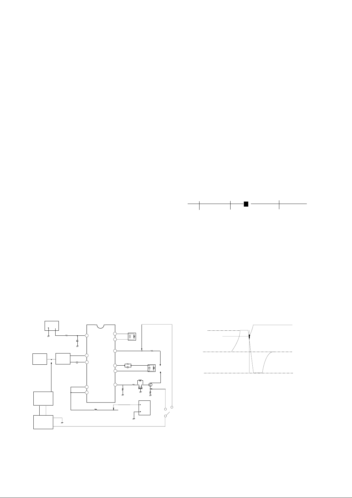
1) Connect the output of Sweamer Generator like <Fig 1>.
Here, set the output of Sweamer Gen. to 100±5dBu.
POWER
SUPPLY
-
TUNER
IF
SWEEMAR
GENERATOR
+
ALIGNMENT
SCOPE
TP2
+
SAW
FILTER
470/0.5W
7.5V
TP11
+
C122
2
C508
8
9
IC501
LA7674
11
14
R591
TP12
<Figure 1>
L501
VCO COIL
51
50
47
R520
46
C521
45
44
R518
TP4
R507
L506
AFT COIL
9V
Q503
R517
L503
Z502
TP3
L502
12.5V
+
POWER
-
SUPPLY
D502
+B
2) Connect H.Scope and Pulse output of Sweamer Generator
to H.Input and Marker input of Alignment Scope,
respectively.
3) Apply AGC Voltage(D.C.) to TP11 of IC201.(7.5±0.05V)
4) Apply B+ of IC201 to TP12 of R591.(12.0±0.1V)
5) Set VR526(AGC Adjustment) to mechanical center.
1.3. Adjustment
A. VCO
1) Set the vertical range of Alignment Scope to 1V/DIV and
CAL position, and, by applying D.C. 0~9V, do DC
Calibration to place D.C 4.5V point of waveform to center of
Screen.
2) Connect the Input terminal of Alignment Scope to
TP3(Video Detection Output), and set Vertical Variable
Switch to CAL position.
3) Apply AGC Voltage to TP11 of IC201 through 470§to be
7.5±0.05V
4) Adjust L501 so that BEAT appears on 45.75MHz Marker
like <Fig 2> If not, adjust again after attenuating output 10
~20dBu.
42.75
B. AFT
1) Connect the Input of Alignment Scope to TP4 with keeping
DC voltage of 2pin of IC201.
2) Keep the output of Sweamer Generator 100±5dBu.
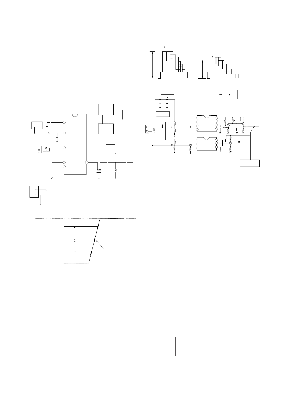
3) Adjust L506 so that waveform of Alignment Scope to be
that of <Fig 3>.
4) Adjust Vertical Volume of Alignment Scope to place DC
level of waveform to center (4.5V) and 45.75MHz Marker to
7.5V¡0.5V.
9V
8V
AFT
0V
2. SIF Adjustment
VCO
2.1. Necessary Instruments
1) Sweamer Generator : can sweep 3~6MHz
2) Plug In Unit : with 4.5MHz Marker
3) Alignment Scope : X-Y mode(can measurable 10mV~
20Vp-p)
4) DC Power Supply : 13.5V, over 300mA
5) DC Power Supply : 0~12V variable
f (MHz)
45.0 47.25
45.75MHz
(Turn L105 so that the position of Beat
is same with 45.75MHz Marker)
<Figure 2>
45.75 MARKER
<Figure 3>
- 1-
2.2. Adjustment
1) Connect Sweamer Generator and Alignment Scope the
same method of VIF adjustment.
2) Connect the output of Sweamer Generator to TP5 like <Fig 4 >.
3) Connect the Input of Alignment Scope to TP6.
4) Apply AGC voltage of IC201 to TP11(7.5±0.05V).
5) Apply B+ of IC201 to TP12.
6) Adjust L502 S-shaped waveform of Alignment Scope to be
that of <Fig 5>.
Adjust (A=B)
Because 4.5MHz Marker doesn’t with horizontal line, apply
(a) marker(4.5MHz) to be the center of (b), (c)Markers.
100% WHITE
75% WHITE
A
B
DC POWER
SUPPLY
DC 12V
TP13
R591
TP12
<Figure 6>
DC POWER
SUPPLY
DC 12.5V
12.5V
POWER
SUPPLY
9V
A = B
+B
POWER
-
+
ALIGNMENT
SCOPE
TP6
7.5V
TP11
+
C508
1
2
4
11
14
IC501
LA7674
SWEEMAR
GENERATOR
TP5
45
C515
C516
Z501
SUPPLY
C509
+
470/0.5W
L502
SIF COIL
R591
-
TP12
C206
ZD201
PATTERN
A/V IN
VIDEO
SOUND
R609
GENERATOR
TP8
A
R210
1
2
Q206
IC202
C204
C507
3
4
1
Q603
2
IC601
3
COLD
8
7
6
5
8
7
6
HOT
VR202
Q201
R618
Q601
Q202
L201
C510
OSCILLOSCOPE
C201
6.0MHz
VIDEO
SOUND
TP10
D
<Figure 7>
3.3 Adjustment
Adjust VR202 to get Luminance signal(Color Bar) level like
below. ( Refer to <Fig 6> )
1) White 100% modulated 1.78±0.1Vp-p
<Figure 4>
2) White 75% modulated 1.46±0.1Vp-p
4. Automatic Gain Control(AGC) Adjustment
4.1Turn on a SET and receive Digital Pattern of 65¡1dB through
A
(b)
(a)
B
4.5 MARKER
75§Ant. terminal.
4.2 Connect DMM(Digital Multi-Meter) to J27.
4.3 Adjust VR101 to read 5.7±0.05V of DMM.
(Where, you can set proper AGC voltage according to signal
condition.)
0V
(c)
<Figure 5>
3. Composite Video Signal Adjustment
3.1.Necessary Instruments
1) Pattern Generator : PM5518(PHILIPS) or Equivalents
7 Step Color Bar Pattern with 75§out
2) Oscilloscope : VP-5650A or Equivalents
can measure over 1.0Vp-p
Vertical Freq. : over 4MHz
3) DC Power Supply : 12.2±0.2V/400mA 2EA
3.2. Preliminary Steps
1) Connect the output of Pattern Generator to TP8 like <Fig 7>.
Where, the output of Pattern Generator is 1.0Vp-p.(Point
position “A”)
2) Connect DC Power Supply to TP12 and TP13.
Where, devide Ground of TP12 and TP13(HOT/COLD).
3) Connect probe to TP10(point “D”).
- 2-
5. Purity and Convergence Adjustment
This adjustment should be made when a complete re-alignment
is required or a new picture tube is installed.
5.1 Purity Adjustment
5.1.1 Necessary instruments and Preliminary steps
1) Pattern Generator : 216/1 or Equivalents
2) Degauss CPT and Cabinet with Degaussing coil.
3) Maximize Contrast level.
4) Pre-adjust the DY.
5.1.2 Adjustment
1) Receive Raster signal(Red).
2) Push the DY to get Picture like <Fig 8>.
3) Adjust 2-pole magnet to place RED center of screen
orthogonally.
B
<Figure 8>
RG
 Loading...