

Page 1
- 1 -
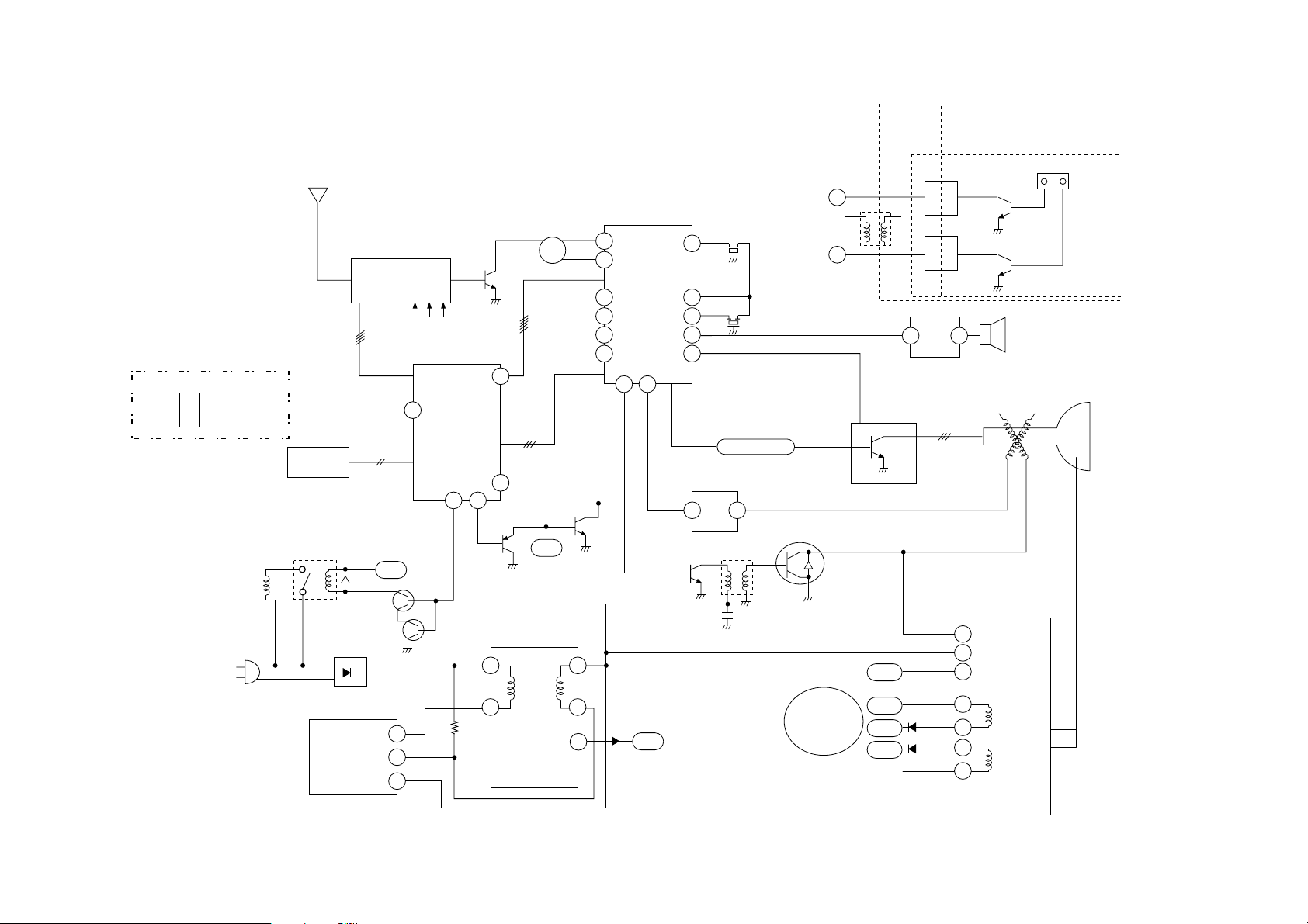
BLOCK DIAGRM
TUNER
HOT
COLD
TU100
IC2
D801
IC301
IC801
RL801
D/G
COIL
IC1
PA1
5V 12V 33V
LOCK
CLOCK
DATA
CS
35
3
1
2
5
39 41
SDA/SCL
R, G, B, Ys
Q806
Q10
Q401
Q402
1877
H. D. T
Q805
TMP67CC31
IC501
8
9
50
51
45
46
44
48
T402
FBT
1
3
40
34
6
21
23 28
LA7674
SMPS TRANS
TX
IC601
PRE-AMP
EEPROM
12V
R-Y, B-Y, G-Y
5V
24V
180V
STR50092K
PWR
Q11
FBP
FROM FBT
H.Vcc of
IC501
AFT
HV
Z101
VIF
SIF
VCO
AFT
SHARP
BRI
COLOR
TINT
CONT
PRE-AMP.
Q102
SIF-IN
DET-OUT
SFE4.5
TPS4.5
SP
AUDIO IN VIDEO IN
2 12
IC602
CPT
1 4
T403
-Y
TDA
2006
IC202
Q208
Q603
3
2
9
5
6
10
HT
24V
12V
FBP
B+
COL
CPT
TO IC1
TO CPT
TO T403
CPT
JA001
PCB
13
26
D/G
3
1
6
5
8
Page 2
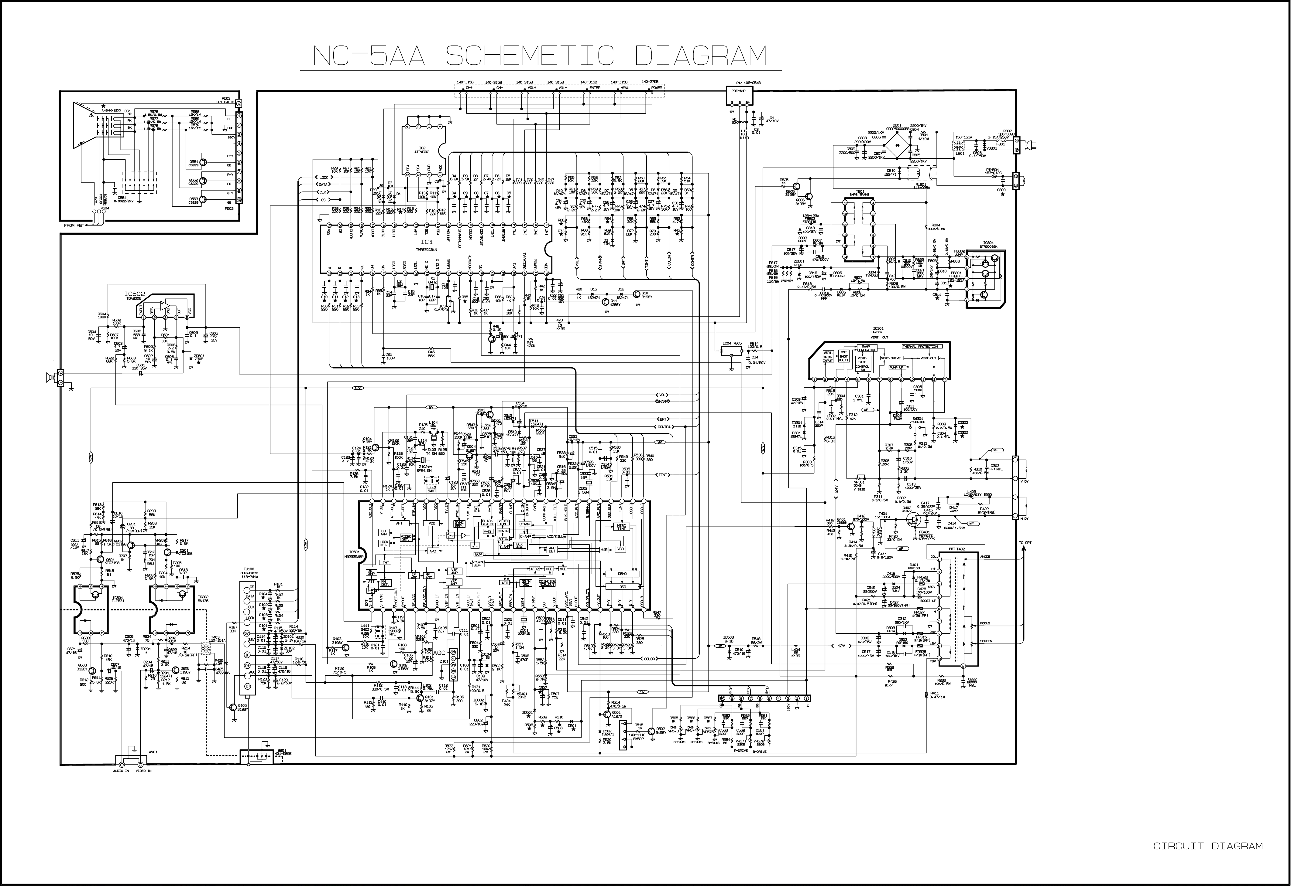
Page 3
ADJUSTMENT INSTRUCTION
These instructions are applied to only NC-5AA chassis.
Notes
1.So this is a hot chassis, you must be careful, and be caution
not to touch 1st and 2nd concurrently.
2.Adjustment must be done in the correct order.
3.Power supply of a SET which is adjusted is 100~240V
A.C./50~60Hz.
4.The receiver must be operated for about 30 minutes proir to
the adjustment.
CONTENTS
1) VIF, AFT and SIF Adjustment
2) Sound Multiplex Adjustment
3) FOCUS Adjustment
4) AGC Adjustment
4)-1 Picture AGC Adjustment
5) V-Size and V-Center Adjustment
6) Horizontal Size, Center and Side Pincushion Adjustment
7) Purity and Convergence Adjustment
8) White Balance Adjustment
9) SUB-Bright Adjustment
10) Vertical Center Adjustment
11) Horizontal Center Adjustment
1. VCO and AFT Adjustment
This Adjustment must be applied only to PCB Assy.
1.1. Necessary Instruments
1) Sweamer Generator : can sweep 35MHz~55MHz(over
120dBu)
2) PLUG in Unit : With PIF(45.75MHz), SIF(41.25MHz) Marker
3) Alignment Scope : X-Y mode, 10mV~20V Variable
4) D.C. Power Supply : 0~12V Variable
5) D.C. Power Supply : 13.5V±0.2V (over 300mA)
6) Digital Multimeter
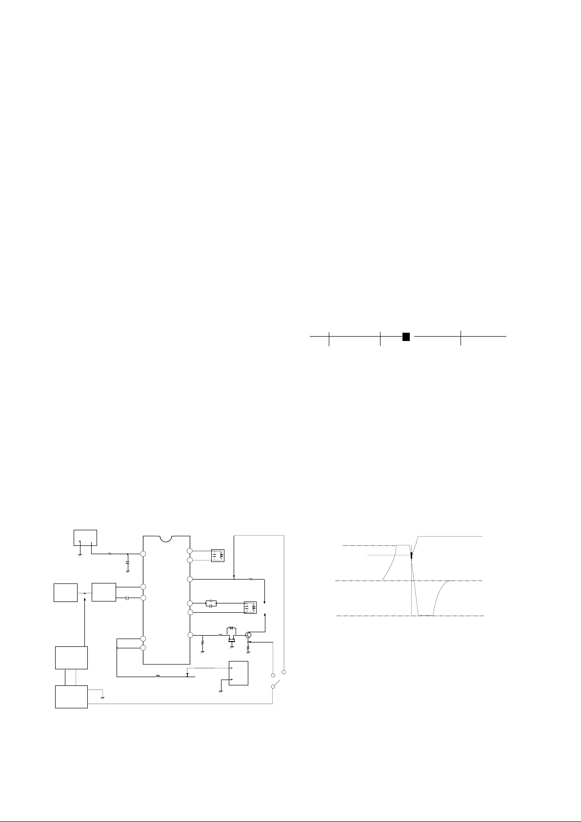
1.2. Preliminary Steps
1) Connect the output of Sweamer Generator like <Fig 1>.
Here, set the output of Sweamer Gen. to 100±5dBu.
POWER
SUPPLY
-
TUNER
IF
SWEEMAR
GENERATOR
+
ALIGNMENT
SCOPE
TP2
+
SAW
FILTER
470/0.5W
7.5V
TP11
+
C122
2
C508
8
9
IC501
LA7674
11
14
R591
TP12
<Figure 1>
L501
VCO COIL
51
50
47
R520
46
C521
45
44
R518
TP4
R507
L506
AFT COIL
9V
Q503
R517
L503
Z502
TP3
L502
12.5V
+
POWER
-
SUPPLY
D502
+B
2) Connect H.Scope and Pulse output of Sweamer Generator
to H.Input and Marker input of Alignment Scope,
respectively.
3) Apply AGC Voltage(D.C.) to TP11 of IC201.(7.5±0.05V)
4) Apply B+ of IC201 to TP12 of R591.(12.0±0.1V)
5) Set VR526(AGC Adjustment) to mechanical center.
1.3. Adjustment
A. VCO
1) Set the vertical range of Alignment Scope to 1V/DIV and
CAL position, and, by applying D.C. 0~9V, do DC
Calibration to place D.C 4.5V point of waveform to center of
Screen.
2) Connect the Input terminal of Alignment Scope to
TP3(Video Detection Output), and set Vertical Variable
Switch to CAL position.
3) Apply AGC Voltage to TP11 of IC201 through 470§to be
7.5±0.05V
4) Adjust L501 so that BEAT appears on 45.75MHz Marker
like <Fig 2> If not, adjust again after attenuating output 10
~20dBu.
42.75
B. AFT
1) Connect the Input of Alignment Scope to TP4 with keeping
DC voltage of 2pin of IC201.
2) Keep the output of Sweamer Generator 100±5dBu.
3) Adjust L506 so that waveform of Alignment Scope to be
that of <Fig 3>.
4) Adjust Vertical Volume of Alignment Scope to place DC
level of waveform to center (4.5V) and 45.75MHz Marker to
7.5V¡0.5V.
9V
8V
AFT
0V
2. SIF Adjustment
VCO
2.1. Necessary Instruments
1) Sweamer Generator : can sweep 3~6MHz
2) Plug In Unit : with 4.5MHz Marker
3) Alignment Scope : X-Y mode(can measurable 10mV~
20Vp-p)
4) DC Power Supply : 13.5V, over 300mA
5) DC Power Supply : 0~12V variable
f (MHz)
45.0 47.25
45.75MHz
(Turn L105 so that the position of Beat
is same with 45.75MHz Marker)
<Figure 2>
45.75 MARKER
<Figure 3>
- 1-
Page 4

2.2. Adjustment
1) Connect Sweamer Generator and Alignment Scope the
same method of VIF adjustment.
2) Connect the output of Sweamer Generator to TP5 like <Fig 4 >.
3) Connect the Input of Alignment Scope to TP6.
4) Apply AGC voltage of IC201 to TP11(7.5±0.05V).
5) Apply B+ of IC201 to TP12.
6) Adjust L502 S-shaped waveform of Alignment Scope to be
that of <Fig 5>.
Adjust (A=B)
Because 4.5MHz Marker doesn’t with horizontal line, apply
(a) marker(4.5MHz) to be the center of (b), (c)Markers.
100% WHITE
75% WHITE
A
B
DC POWER
SUPPLY
DC 12V
TP13
R591
TP12
<Figure 6>
DC POWER
SUPPLY
DC 12.5V
12.5V
POWER
SUPPLY
9V
A = B
+B
POWER
-
+
ALIGNMENT
SCOPE
TP6
7.5V
TP11
+
C508
1
2
4
11
14
IC501
LA7674
SWEEMAR
GENERATOR
TP5
45
C515
C516
Z501
SUPPLY
C509
+
470/0.5W
L502
SIF COIL
R591
-
TP12
C206
ZD201
PATTERN
A/V IN
VIDEO
SOUND
R609
GENERATOR
TP8
A
R210
1
2
Q206
IC202
C204
C507
3
4
1
Q603
2
IC601
3
COLD
8
7
6
5
8
7
6
HOT
VR202
Q201
R618
Q601
Q202
L201
C510
OSCILLOSCOPE
C201
6.0MHz
VIDEO
SOUND
TP10
D
<Figure 7>
3.3 Adjustment
Adjust VR202 to get Luminance signal(Color Bar) level like
below. ( Refer to <Fig 6> )
1) White 100% modulated 1.78±0.1Vp-p
<Figure 4>
2) White 75% modulated 1.46±0.1Vp-p
4. Automatic Gain Control(AGC) Adjustment
4.1Turn on a SET and receive Digital Pattern of 65¡1dB through
A
(b)
(a)
B
4.5 MARKER
75§Ant. terminal.
4.2 Connect DMM(Digital Multi-Meter) to J27.
4.3 Adjust VR101 to read 5.7±0.05V of DMM.
(Where, you can set proper AGC voltage according to signal
condition.)
0V
(c)
<Figure 5>
3. Composite Video Signal Adjustment
3.1.Necessary Instruments
1) Pattern Generator : PM5518(PHILIPS) or Equivalents
7 Step Color Bar Pattern with 75§out
2) Oscilloscope : VP-5650A or Equivalents
can measure over 1.0Vp-p
Vertical Freq. : over 4MHz
3) DC Power Supply : 12.2±0.2V/400mA 2EA
3.2. Preliminary Steps
1) Connect the output of Pattern Generator to TP8 like <Fig 7>.
Where, the output of Pattern Generator is 1.0Vp-p.(Point
position “A”)
2) Connect DC Power Supply to TP12 and TP13.
Where, devide Ground of TP12 and TP13(HOT/COLD).
3) Connect probe to TP10(point “D”).
- 2-
5. Purity and Convergence Adjustment
This adjustment should be made when a complete re-alignment
is required or a new picture tube is installed.
5.1 Purity Adjustment
5.1.1 Necessary instruments and Preliminary steps
1) Pattern Generator : 216/1 or Equivalents
2) Degauss CPT and Cabinet with Degaussing coil.
3) Maximize Contrast level.
4) Pre-adjust the DY.
5.1.2 Adjustment
1) Receive Raster signal(Red).
2) Push the DY to get Picture like <Fig 8>.
3) Adjust 2-pole magnet to place RED center of screen
orthogonally.
B
<Figure 8>
RG
Page 5

4) Pre-fix 2-pole magnet after adjustment with Lock Ring.
,,,,,
5) Pull the DY back slowly to get uniformly RED picture and fix
it.
5.2 Convergence Adjustment
5.2.1 Necessary Instruments
1) Pattern Generator : 216/1 or Equivalents
2) Degaussing coil
5.2.2 Preliminary Steps
1) Do this adjustment after operating the SET more than 30
minutes.
2) Degauss CPT and Cabinet with Degaussing coil.
3) Receive Cross hatch pattern.
4) Adjust Contrast and Bright properly.
5) Untighten half-fixed Magnet Assy lock ring
5.2.3 Adjustment
A. Center(Static) Convergence Adjustment
1) Unify Red and Blue vertical lines at center of screen by
varying the angle of two tabs of 4-pole magnet.
2) Rotate tab with sustaining the angle of item 1) and unify
Red and Blue vertical lines at center of screen.
3) Unify Red,Blue and Green vertical lines by adjusting two
tab2 of 6-pole magnet.
4) Rotate tab with sustaining the angle of item 3) and unify
Red,Blue and Green vertical lines.
5) To get more detail adjustment repeat 1),2) with
remembering changes of Red,Blue and Green.
6) Fix magnet assy lock ring.
B. Dynamic Convergence Adjustment
1) Prepare bonded rubber wedge.
2) Adhere rubber wedge to “A” part halfly.
(Don’t remove paper of bonding part.)
3) Move the DY every direction to get best convergence in
every corner.
4) Adhere rubber wedge to bottom of CPT.(Refer <Fig 9>).
5) After checking the locatons of 3 wedges and check
Convergence.
6) Paint white lacquer on DY fixing nut and magnet.
ADHESIVE TAPE
RUBBER
WEDGES
TEMPORARY
MOUNTING
DEFLECTION YOKE
PURITY &CONVERGENCE
MAGNET ASSEMBLY
,,,
,,
,,
,,,
PURITY MAGNET
4-POLE
GLASS CLOTH TAPE
6-POLE
6. White Balance
6.1 White Balance Adjustment
6.1.1 Necessary Instrument
1) White BAlance Meter
6.1.2 Preliminary Steps
1) Do this adjustment after operating the SET more than 30
minutes.
2) Receive Standard White pattern.
3) Adjust under “APC ON” condition.
4) Turn Screen VR CCW.
5) Set Red driver(VR571) and Blue driver(VR572) to
mechanical center.
6) Set Red Bias(VR574) ,Blue Bias(VR575) and Green
Bias(VR573) to 1/3 point to Clock-wise from full CCW.
7) Set SVC SW to “SVC” to get Horizontal line.
6.1.3 Adjustment
1) Turn screen VR slowly to see first horizontal line on screen
2) Make horizontal line white with 2 Bias VRs which aren’t
displayed in 1).
3) Vary screen VR to get very dim horizontal line.
4) Set SVC SW to “Normal” position.
5) Receive adjustment signal-White in upper and Black in
Lower.
6) Vary Red driver(VR571) and Blue driver(VR572) to get
White screen in White.
7) Vary Bias and Drivers to get the best screen in White and
Black.
8) Check adjustment condition with White Balance Meter.
9) Refer below for Adjustment
Color Temperature
10,000K
High Light : 40fl
Low Right : 4fl
X
0.281
Y
0.288
7. Focus Adjustment
1) Receive Digital pattern.
2) Set screen conditon to “APC ON”.
3) Turn Focus VR to get the best condition in center and
every corner.
8. Sub-Bright Adjustment
1) Receive Digital pattern.
2) Do this adjustment after operating the SET more than 30
minutes.
3) After selecting Sub-mode with SVC Remocon and vary to
distinguish 4 and 5 step of Gray scale.
9. Vertical Size Adjustment
1) Receive Digital pattern and set screen conditon to “APC
ON”.
2) Vary Vertical Size adjustment VR(VR301) to reach inner
circle of large circle to edge of frame.
30¡£
RUBBER WEDGES
LOCATION
30¡£
30¡£
DEFLECTION YOKE
<Figure 9>
ADHESIVE
10. Vertical Center Adjustment
1) Receive Digital pattern and set screen condition to “APC
ON”.
2) Adjust the center of screen with SVC SW(SW301) to place
center.
11. Horizontal Center Adjustment
1) Receive Digital pattern and set screen condition to “APC
ON”.
2) Adjust the center of screen with VR505 to place center.
- 3-
Page 6

LOCA. NO PART NO DESCRIPTION
IC1
IC2
IC3
IC301
IC4
IC501
IC602
IC801
Q10
Q102
Q105
Q11
Q2
Q401
Q402
Q501
Q502
Q503
Q504
Q505
Q506
Q561(14")
"(20")
Q562(14")
"(20")
Q563(14")
"(20")
Q803
Q804
Q805
Q806
D10
D15
D16
D2
D3
D302
D303
D4
D401
D5
D501
D503
D504
D505
D506
0ITO850810B
0IAL240210A
0IKE704200B
0ISA783700A
0IKE780500D
0ISA767400A
0ISG200600A
0IGL500920D
0TR319809AA
0TR319709AB
0TR319809AA
0TR126609AA
0TR319809AA
0TR322809AA
0TR187700AA
0TR319809AA
0TR319809AA
0TR319809AA
0TR319809AA
0TR319809AA
0TR127009AA
0TR320709AA
0TR322900AA
0TR320709AA
0TR322900AA
0TR320709AA
0TR322900AA
0TR319809AA
0TR319809AA
0TR319809AA
0TR322709AA
0DD247109AA
0DD247109AA
0DD247109AA
0DD247109AA
0DD247109AA
0DD150009CC
0DD060009AC
0DD247109AA
0DD150009CC
0DD247109AA
0DD247109AA
0DD150009CC
0DD060009AC
0DD247109AA
0DD247109AA
IC,LG8508-10B(TMP87CH31N-344
IC,AT24C02-10PC 8D EEPROM(2K,IIC)
IC,KIA7042P 3P 4.2V RESET
IC,GL7837(LA7837) 13SIP V/O.
IC,KIA7805P(KIA78005AP),KEC
IC,LA7674 52SD NTSC 1 CHIP
IC,TDA2006,SOUND
IC,STR50092D NEW FORMING
TR,KTC3198-TP-Y (KTC1815)KEC
TR,KTC3197,TP(KTC388A),KEC
TR,KTC3198-TP-Y (KTC1815)KEC
TR,KTA1266-TP-Y (KTA1015) KEC
TR,KTC3198-TP-Y (KTC1815)KEC
TR,KTC3228-0 TP(KTC2383),KEC
TR,2SD1877 SANYO
TR,KTC3198-TP-Y (KTC1815)KEC
TR,KTC3198-TP-Y (KTC1815)KEC
TR,KTC3198-TP-Y (KTC1815)KEC
TR,KTC3198-TP-Y (KTC1815)KEC
TR,KTC3198-TP-Y (KTC1815)KEC
TR,KTA1270-TP-Y (KTA562TM)KEC
TR,KTC3207,TP(KTC2482),KEC
TR,KTC3229 (KTC2068),KEC
TR,KTC3207,TP(KTC2482),KEC
TR,KTC3229 (KTC2068),KEC
TR,KTC3207,TP(KTC2482),KEC
TR,KTC3229 (KTC2068),KEC
TR,KTC3198-TP-Y (KTC1815)KEC
TR,KTC3198-TP-Y (KTC1815)KEC
TR,KTC3198-TP-Y (KTC1815)KEC
TR,KTC3227-Y,TP(KTC1627A),KEC
DIODE,1S2471
DIODE,1S2471
DIODE,1S2471
DIODE,1S2471
DIODE,1S2471
DIODE,RGP15G
DIODE,TVR06J 0.6A/600V 250NS
DIODE,1S2471
DIODE,RGP15G
DIODE,1S2471
DIODE,1S2471
DIODE,RGP15G
DIODE,TVR06J 0.6A/600V 250NS
DIODE,1S2471
DIODE,1S2471
LOCA. NO PART NO DESCRIPTION
D507
D508
D509
D510
D511
D6
D7
D8
D801
D803
D806
D807
D809
D810
D9
ZD101
ZD102
ZD103
ZD301
ZD502
ZD504
ZD506
C1
C108
C112
C113
C114
C115
C116
C118
C119
C120
C121
C122
C14
C15
C16
C17
C18
C19
C2
C20
C21
C22
C222
C23
C25
C26
C27
0DD247109AA
0DD247109AA
0DD247109AA
0DD247109AA
0DD247109AA
0DD247109AA
0DD247109AA
0DD247109AA
0DD260000BB
0DD150009CA
0DD060009AC
0DD150009CA
0DD200009AU
0DD247109AA
0DD247109AA
0DZ510009AB
0DZ300009BA
0DZ120009AA
0DZ120009AA
0DZ240009BC
0DZ910009BA
0DZ360009DA
0CE476DF618
0CE226DK618
0CN1030F679
0CN1030F679
0CX3000K409
0CE475DK618
0CN1020K519
0CN1030F679
0CE108BF618
0CE225DK618
0CN1030F679
0CN1030F679
0CX1500K409
0CX1500K409
0CX1600K409
0CX1600K409
0CN1030F679
0CN1010K519
0CN1030F679
0CN1030F679
0CN1030F679
0CN1030F679
0CQ2231N509
0CE227DF618
0CN1010K519
0CE475DK618
0CE475DK618
DIODE,1S2471
DIODE,1S2471
DIODE,1S2471
DIODE,1S2471
DIODE,1S2471
DIODE,1S2471
DIODE,1S2471
DIODE,1S2471
DIODE,BRIDGE D2SBA60(STK)
DIODE,RGP15J
DIODE,TVR06J 0.6A/600V 250NS
DIODE,RGP15J
DIODE,R-2G V(1)
DIODE,1S2471
DIODE,1S2471
DIODE,ZENER,MTZ5.1B
DIODE,ZENER,MTZ30B
DIODE,ZENER,Z12BM TA
DIODE,ZENER,Z12BM TA
DIODE,ZENER,MTZ2.4B 2.4V
DIODE,ZENER,MTZ9.1B
DIODE,ZENER,MTZ3.6B
C,ELECTROLYTIC 47UF STD 16V M
C,ELECTROLYTIC 22UF STD 50V M
C,TUBULA(HIGH DIELE) 0.01MF 16V M
C,TUBULA(HIGH DIELE) 0.01MF 16V M
C,TUBULA(T.C) 30P 50V J
C,ELECTROLYTIC 4.7UF STD 50V M
C,TUBULA(HIGH DIELE) 1000PF 50V K
C,TUBULA(HIGH DIELE) 0.01MF 16V M
C,ELECTROLYTIC 1000UF KME 16V M
C,ELECTROLYTIC 2.2UF STD 50V M
C,TUBULA(HIGH DIELE) 0.01MF 16V M
C,TUBULA(HIGH DIELE) 0.01MF 16V M
C,TUBULA(T.C) 15PF 50V J
C,TUBULA(T.C) 15PF 50V J
C,TUBULA(T.C) 16P 50V J
C,TUBULA(T.C) 16P 50V J
C,TUBULA(HIGH DIELE) 0.01MF 16V M
C,TUBULA(HIGH DIELE) 100PF 50V K
C,TUBULA(HIGH DIELE) 0.01MF 16V M
C,TUBULA(HIGH DIELE) 0.01MF 16V M
C,TUBULA(HIGH DIELE) 0.01MF 16V M
C,TUBULA(HIGH DIELE) 0.01MF 16V M
C,POLYESTER(MYLAR) 0.022MF 100V K
C,ELECTROLYTIC 220UF STD 16V M
C,TUBULA(HIGH DIELE) 100PF 50V K
C,ELECTROLYTIC 4.7UF STD 50V M
C,ELECTROLYTIC 4.7UF STD 50V M
- 21 -
REPLACEMENT PARTS LIST
RUN DATE:970313
CAPACITOR
TRANSISTOR
IC
DIODE
Page 7

LOCA. NO PART NO DESCRIPTION
C28
C29
C3
C30
C301
C302
C303
C304
C306
C307(14")
"(20")
C309
C31
C310
C311
C312
C313
C314
C315
C34
C350
C411
C412
C414(14")
"(20")
C415
C417
C419
C427
C428
C502
C503
C504
C505
C506
C507
C508
C509
C510
C511
C513
C515
C516
C518
C519
C52
C521
C522
C523
C524
C525
C526
C527
C528
C529
0CE475DK618
0CE475DK618
0CN1030F679
0CE475DK618
181-444P
0CQ1031N509
0CQ1041N509
0CQ1041N509
0CE108DJ618
0CE4749K538
0CE6846K618
0CE476DF618
0CE475DK618
0CE6846K618
0CE107DK618
0CK56101515
0CE108DJ618
0CN3910K519
0CN1030F679
0CK1030K945
0CX2000K409
0CE2251P618
0CK1020W515
181-015F
181-015J
181-091G
181-013D
0CK2220W515
181-102P
0CE107DN618
0CE475DK618
0CN1030F679
0CN1030F679
0CN1030F679
0CE474DK618
0CN1030F679
0CE104DK618
0CQ1031N509
0CE105DK618
0CE108DF618
0CN1030F679
0CX1800K409
0CX3900K409
0CK56101515
181-003F
0CE476DF618
0CX1800K409
0CE475DK618
0CE474DK618
0CN1030F679
0CN1030F679
0CQ1031N509
0CX1600K409
0CE476DF618
0CN8200K519
C,ELECTROLYTIC 4.7UF STD 50V M
C,ELECTROLYTIC 4.7UF STD 50V M
C,TUBULA(HIGH DIELE) 0.01MF 16V M
C,ELECTROLYTIC 4.7UF STD 50V M
C,MPE ECQ-V1H564JZ3
C,POLYESTER(MYLAR) 0.01U 100V K
C,POLYESTER(MYLAR) 0.1MF 100V L
C,POLYESTER(MYLAR) 0.1MF 100V L
C,ELECTROLYTIC 1000UF STD 35V M
C,ELECTROLYTIC 0.47UF KU 50V K
C,ELECTROLYTIC 0.68UF KU 50V M
C,ELECTROLYTIC 47UF STD 16V M
C,ELECTROLYTIC 4.7UF STD 50V M
C,ELECTROLYTIC 0.68U SMS 50V M
C,ELECTROLYTIC 100UF STD 50V M
C,CERAMIC(HIGH DIELE) 560P 1KV K
C,ELECTROLYTIC 1000UF STD 35V M
C,TUBULA(HIGH DIELE) 390P 50V K
C,TUBULA(HIGH DIELE) 0.01MF 16V M
C,CERAMIC(HIGH DIELE) 0.01MF 50V Z
C,TUBULA(T.C) 20P 50V J
C,ELECTROLYTIC 2.2M SM 160V M
C,CERAMIC(HIGH DIELE) 1000PF 500V K
C,MPP 1600V 0.0073UF H
C,MPP 1600V 0.0086UF H
C,DE0907 R471K 2K
C,MPP 200V 0.43uF J
C,CERAMIC(HIGH DIELE) 2200PF 500V K
C,HR 160V 33UF TP
C,ELECTROLYTIC 100UF STD 100V M
C,ELECTROLYTIC 4.7UF STD 50V M
C,TUBULA(HIGH DIELE) 0.01MF 16V M
C,TUBULA(HIGH DIELE) 0.01MF 16V M
C,TUBULA(HIGH DIELE) 0.01MF 16V M
C,ELECTROLYTIC 0.47UF STD 50V M
C,TUBULA(HIGH DIELE) 0.01MF 16V M
C,ELECTROLYTIC 0.1UF STD 50V M
C,POLYESTER(MYLAR) 0.01U 100V K
C,ELECTROLYTIC 1UF STD 50V M
C,ELECTROLYTIC 1000UF STD 16V M
C,TUBULA(HIGH DIELE) 0.01MF 16V M
C,TUBULA(T.C) 18PF 50V J
C,TUBULA(T.C) 39PF 50V J
C,CERAMIC(HIGH DIELE) 560P 1KV K
C,ELECTROLYTIC 250V 4.7UF T HR (85)
C,ELECTROLYTIC 47UF STD 16V M
C,TUBULA(T.C) 18PF 50V J
C,ELECTROLYTIC 4.7UF STD 50V M
C,ELECTROLYTIC 0.47UF STD 50V M
C,TUBULA(HIGH DIELE) 0.01MF 16V M
C,TUBULA(HIGH DIELE) 0.01MF 16V M
C,POLYESTER(MYLAR) 0.01U 100V K
C,TUBULA(T.C) 16P 50V J
C,ELECTROLYTIC 47UF STD 16V M
C,TUBULA(HIGH DIELE) 82P 50V K B
LOCA. NO PART NO DESCRIPTION
C530
C531
C532
C533
C534
C535
C536
C537
C538
C539
C540
C543
C544
C545
C546
C547
C548
C549
C550
C551
C553
C554
C555
C556
C557
C558
C559(14")
"(20")
C560
C564
C564
C565
C571
C578
C601
C602
C603
C604
C605
C606
C608
C609
C801
C804
C805
C806
C807
C809
C810
C812
C816
C817
C818(14")
"(20")
C819
0CN1030F679
0CX5600K409
0CN1030F679
0CC5100K405
0CE106DF618
0CX2000K409
0CN1030F679
0CE1056K635
0CE477DF618
0CN1030F679
0CN1030F679
0CE105DK618
0CN1030F679
0CE105DK618
0CN5610K519
0CQ1531N509
0CE225DK618
0CN2220F569
0CQ2221N509
0CE475DK618
0CE225DK618
0CE105DK618
0CE226DF618
0CN1030F679
0CE108DF618
0CN8210K519
0CN6810K519
0CN8210K519
0CN8210K519
181-033T
181-033T
0CN1030F679
0CX5100K409
0CE476DF618
0CE337DH618
0CE106DK618
0CE475DK618
0CE106DK618
0CE477DJ618
181-007F
0CQ2231N509
0CN1030F679
181-124Y
181-033E
181-033E
181-033E
181-033E
0CK2220W515
181-093C
0CQ1531N509
0CE227DP61A
0CE108DJ618
0CK47101515
0CK56101515
0CK4710W515
C,TUBULA(HIGH DIELE) 0.01MF 16V M
C,TUBULA(T.C) 56P 50V J
C,TUBULA(HIGH DIELE) 0.01MF 16V M
C,CERAMIC(TEMP COMP) 51P 50V J
C,ELECTROLYTIC 10UF STD 16V M
C,TUBULA(T.C) 20P 50V J
C,TUBULA(HIGH DIELE) 0.01MF 16V M
C,ELECTROLYTIC 1UF SMS 50V M
C,ELECTROLYTIC 470UF STD 16V M
C,TUBULA(HIGH DIELE) 0.01MF 16V M
C,TUBULA(HIGH DIELE) 0.01MF 16V M
C,ELECTROLYTIC 1UF STD 50V M
C,TUBULA(HIGH DIELE) 0.01MF 16V M
C,ELECTROLYTIC 1UF STD 50V M
C,TUBULA(HIGH DIELE) 560P 50V K
C,POLYESTER(MYLAR) 0.015MF 100V K
C,ELECTROLYTIC 2.2UF STD 50V M
C,TUBULA(HIGH DIELE) 2200P 16V K
C,POLYESTER(MYLAR) 0.0022U 100V K
C,ELECTROLYTIC 4.7UF STD 50V M
C,ELECTROLYTIC 2.2UF STD 50V M
C,ELECTROLYTIC 1UF STD 50V M
C,ELECTROLYTIC 22UF STD 16V M
C,TUBULA(HIGH DIELE) 0.01MF 16V M
C,ELECTROLYTIC 1000UF STD 16V M
C,TUBULA(HIGH DIELE) 820P 50V K
C,TUBULA(HIGH DIELE) 680P 50V K
C,TUBULA(HIGH DIELE) 820P 50V K
C,TUBULA(HIGH DIELE) 820P 50V K
CAPACITOR 2KV B 222K TP7.5
CAPACITOR 2KV B 222K TP7.5
C,TUBULA(HIGH DIELE) 0.01MF 16V M
C,TUBULA(T.C) 51P 50V J
C,ELECTROLYTIC 47UF STD 16V M
C,ELECTROLYTIC 330UF STD 25V M
C,ELECTROLYTIC 10UF STD 50V M
C,ELECTROLYTIC 4.7UF STD 50V M
C,ELECTROLYTIC 10UF STD 50V M
C,ELECTROLYTIC 470UF STD 35V M
C,MPE 50V 0.22UF J
C,POLYESTER(MYLAR) 0.022MF 100V K
C,TUBULA(HIGH DIELE) 0.01MF 16V M
CAPACITOR 400V 220UF M
CAPACITOR 1KV B 2200PF K
CAPACITOR 1KV B 2200PF K
CAPACITOR 1KV B 2200PF K
CAPACITOR 1KV B 2200PF K
C,CERAMIC(HIGH DIELE) 2200PF 500V K
CAPACITOR DE 4700PF 400V
C,POLYESTER(MYLAR) 0.015MF 100V K
C,ELECTROLYTIC 220UF STD 160V M
C,ELECTROLYTIC 1000UF STD 35V M
C,CERAMIC(HIGH DIELE) 470P 1KV K
C,CERAMIC(HIGH DIELE) 560P 1KV K
C,CERAMIC(HIGH DIELE) 470PF 500V K
- 22 -
Page 8

LOCA. NO PART NO DESCRIPTION
C820
FB401
FB402
FB801
FB803
FB804
J14
L1
L101
L104
L2
L3
L403(14")
"(20")
L404
L405(14")
"(20")
L501
L502
L503
L504
L506
L507
L508
L509
L511
L514
L801
T401
T402(14")
"(20")
T801
T802
FR315
FR411
FR526
FR527(14")
"(20")
FR528
FR805
R10
R101
R102
R103
R104
R106
R11
R110
R111
R112
0CE476DF618
125-022K
125-022K
125-123A
125-123A
125-022K
125-022K
0LA0102K119
0LA0680K119
125-123A
0LA0272K119
0LA0682K139
150-L01Z
150-L01R
0LA0682K139
150-C04B
150-C02A
150-E08V
150-E08D
0LA0152K119
0LA0272K119
150-E11E
0LA0681K119
0LA0392K119
0LA0682K119
0LA0182K119
0LA1000K119
150-F06B
151-C02B
154-064Y
154-380C
151-A15D
150-F05E
0RF0471H609
0RF0201J607
0RF0470J607
0RF0201J607
0RF0141K607
180-A01B
0RF0470K607
0RF0470H609
0RD2200F609
0RD1001F609
0RD1001F609
0RD1001F609
0RD1001F609
0RS1800K607
0RD1002F609
0RD0822F609
0RD3300H609
0RD5601F609
C,ELECTROLYTIC 47UF STD 16V M
CORE,FERRITE 1UH
CORE,FERRITE 1UH
CORE,FERRITE BFD3565R2F
CORE,FERRITE BFD3565R2F
CORE,FERRITE 1UH
CORE,FERRITE 1UH
INDUCTOR,10UH K
INDUCTOR,0.68UH K
CORE,FERRITE BFD3565R2F
INDUCTOR,27UH K
INDUCTOR,68UH K
COIL,H-LINEARITY 97UH
COIL,H-LINEARITY 38UH
INDUCTOR,68UH K
COIL,CHOKE 18UH R 1018
COIL,CHOKE 10UH R 0814
COIL,VAR,07S 1B 45.75MHZ
COIL,VAR,07S 1B 4.5MHZ
INDUCTOR,15UH K
INDUCTOR,27UH K
COIL,VAR,07S 6D 45.75MHZ
INDUCTOR,6.8UH K
INDUCTOR,39UH K
INDUCTOR,68UH K
INDUCTOR,18UH K
INDUCTOR,100UH K
COIL,LINE FILTER SQE2424 19-35MH
TRANSFORMER,H-DRIVE,EI-19,BULK
FBT,FCB2-14SP3
FBT,FCC2-20SP3
TRANSFORMER,SMPS COIL EE4035 STR50092 W
COIL,LINE FILTER SQ1913 4.5MH
R,FUSIBLE 4.7 1/2W 5
R,FUSIBLE 2 1W 5%
R,FUSIBLE 0.47 1W 5%
R,FUSIBLE 2 1W 5%
R,FUSIBLE 1.40 2W 5%
R,RW RND(G) 2W 0.11 K
R,FUSIBLE 0.47 2W 5%
R,FUSIBLE 0.47 1/2W 5
R,CARBON FILM 220 1/6W 5
R,CARBON FILM 1.0K 1/6W 5
R,CARBON FILM 1.0K 1/6W 5
R,CARBON FILM 1.0K 1/6W 5
R,CARBON FILM 1.0K 1/6W 5
R,METAL FILM OXIDE 180 2W 5%
R,CARBON FILM 10K 1/6W 5
R,CARBON FILM 82 1/6W 5
R,CARBON FILM 330 1/2W 5
R,CARBON FILM 5.6K 1/6W 5
LOCA. NO PART NO DESCRIPTION
R113
R114
R115
R116
R12
R127
R128
R129
R13
R14
R15
R16
R17
R18
R19
R2
R20
R21
R22
R236
R24
R25
R26
R27
R28
R29
R3
R30
R301
R302
R303
R304
R305(14")
"(20")
R306(14")
"(20")
R307
R308
R309
R31
R310
R311
R312(14")
"(20")
R313
R315
R318
R32
R33
R34
R35
R36
R37
R38
R4
0RD0332F609
0RD1001F609
0RD3300F609
0RS0511H609
0RD2200F609
0RD3302F609
0RD1103F609
0RD1001F609
0RD1002F609
0RD1002F609
0RD2200F609
0RD2200F609
0RD2200F609
0RD2200F609
0RD2200F609
0RD1002F609
0RD2200F609
0RD2200F609
0RD2200F609
0RD1002H609
0RD2200F609
0RD1002F609
0RD2200F609
0RD1002F609
0RD2200F609
0RD1002F609
0RD1002F609
0RD2200F609
0RD6801F609
0RD2402F609
0RD0392H609
0RD6802F609
0RD2701F609
0RD3301F609
0RD1003F609
0RD8202F609
0RD2401F609
0RD1103F609
0RD0221H609
0RD2200F609
0RD3300H609
0RD0331H609
0RD4702F609
0RD3902F609
0RD1601H609
0RD0331H609
0RD2002F609
0RD5600F609
0RD1501F609
0RD1001F609
0RD1001F609
0RD1001F609
0RD1001F609
0RD2200F609
0RD7501F609
R,CARBON FILM 33 1/6W 5
R,CARBON FILM 1.0K 1/6W 5
R,CARBON FILM 330 1/6W 5
R,METAL FILM OXIDE 5.1 1/2W 5
R,CARBON FILM 220 1/6W 5
R,CARBON FILM 33K 1/6W 5
R,CARBON FILM 110K 1/6W 5
R,CARBON FILM 1.0K 1/6W 5
R,CARBON FILM 10K 1/6W 5
R,CARBON FILM 10K 1/6W 5
R,CARBON FILM 220 1/6W 5
R,CARBON FILM 220 1/6W 5
R,CARBON FILM 220 1/6W 5
R,CARBON FILM 220 1/6W 5
R,CARBON FILM 220 1/6W 5
R,CARBON FILM 10K 1/6W 5
R,CARBON FILM 220 1/6W 5
R,CARBON FILM 220 1/6W 5
R,CARBON FILM 220 1/6W 5
R,CARBON FILM 10K 1/2W 5
R,CARBON FILM 220 1/6W 5
R,CARBON FILM 10K 1/6W 5
R,CARBON FILM 220 1/6W 5
R,CARBON FILM 10K 1/6W 5
R,CARBON FILM 220 1/6W 5
R,CARBON FILM 10K 1/6W 5
R,CARBON FILM 10K 1/6W 5
R,CARBON FILM 220 1/6W 5
R,CARBON FILM 6.8K 1/6W 5
R,CARBON FILM 24K 1/6W 5
R,CARBON FILM 39 1/2W 5
R,CARBON FILM 68K 1/6W 5
R,CARBON FILM 2.7K 1/6W 5
R,CARBON FILM 3.3K 1/6W 5
R,CARBON FILM 100K 1/6W 5
R,CARBON FILM 82K 1/6W 5
R,CARBON FILM 2.4K 1/6W 5
R,CARBON FILM 110K 1/6W 5
R,CARBON FILM 2.2 1/2W 5
R,CARBON FILM 220 1/6W 5
R,CARBON FILM 330 1/2W 5
R,CARBON FILM 3.3 1/2W 5
R,CARBON FILM 47K 1/6W 5
R,CARBON FILM 39K 1/6W 5
R,CARBON FILM 1.6K 1/2W 5
R,CARBON FILM 3.3 1/2W 5
R,CARBON FILM 20K 1/6W 5
R,CARBON FILM 560 1/6W 5
R,CARBON FILM 1.5K 1/6W 5
R,CARBON FILM 1.0K 1/6W 5
R,CARBON FILM 1.0K 1/6W 5
R,CARBON FILM 1.0K 1/6W 5
R,CARBON FILM 1.0K 1/6W 5
R,CARBON FILM 220 1/6W 5
R,CARBON FILM 7.5K 1/6W 5
- 23 -
RESISTOR
COIL & TRANSFORMER
Page 9

LOCA. NO PART NO DESCRIPTION
R40
R41
R412
R413
R414
R415
R42
R420
R421
R422
R425
R426(14")
"(20")
R43
R44
R45
R46
R47
R48
R5
R501
R502
R503
R504
R505
R506
R507
R508
R509
R510
R511
R512
R513
R514
R515
R516
R517
R518
R519
R520
R522
R523
R524
R525
R532
R533
R534
R535
R536
R537
R538
R539
R54
R540
R541
0RD1200F609
0RD3301F609
0RD6200F609
0RD5100F609
0RD3301H609
0RS2701K607
0RD1001F609
0RD0822H609
0RN0470H609
0RS1001J607
180-C02J
0RD1203H609
0RD8202H609
0RD1002F609
0RD1002F609
0RD6202F609
0RD4702F609
0RD5602F609
0RD5101F609
0RD1001F609
0RD6201F609
0RD2202F609
0RD1001F609
0RD1203F609
0RD2701F609
0RD7501F609
0RD1001F609
0RD3000F609
0RD1002F609
0RD2000F609
0RD3002F609
0RD8201F609
0RD5100F609
0RD3900F609
0RD1003F609
0RD1002F609
0RD1800F609
0RD1001F609
0RD1003F609
0RD3301F609
0RD7501F609
0RD1002F609
0RD2702F609
0RD1001F609
0RD7500F609
0RD1003F609
0RD1001F609
0RD1001F609
0RD3300F609
0RD2701F609
0RD6800F609
0RD1001F609
0RD1802F609
0RD1203F609
0RD1500F609
R,CARBON FILM 120 1/6W 5
R,CARBON FILM 3.3K 1/6W 5
R,CARBON FILM 620 1/6W 5
R,CARBON FILM 510 1/6W 5
R,CARBON FILM 3.3K 1/2W 5
R,METAL FILM OXIDE 2.70K 2W 5%
R,CARBON FILM 1.0K 1/6W 5
R,CARBON FILM 82 1/2W 5
R,METAL FILM 0.47 1/2W 5
R,METAL FILM OXIDE 1K 1W 5%
R,CARBON COMPOSITE 1/2W 10M K
R,CARBON FILM 120K 1/2W 5
R,CARBON FILM 82K 1/2W 5
R,CARBON FILM 10K 1/6W 5
R,CARBON FILM 10K 1/6W 5
R,CARBON FILM 62K 1/6W 5
R,CARBON FILM 47K 1/6W 5
R,CARBON FILM 56K 1/6W 5
R,CARBON FILM 5.1K 1/6W 5
R,CARBON FILM 1.0K 1/6W 5
R,CARBON FILM 6.2K 1/6W 5
R,CARBON FILM 22K 1/6W 5
R,CARBON FILM 1.0K 1/6W 5
R,CARBON FILM 120K 1/6W 5
R,CARBON FILM 2.7K 1/6W 5
R,CARBON FILM 7.5K 1/6W 5
R,CARBON FILM 1.0K 1/6W 5
R,CARBON FILM 300 1/6W 5
R,CARBON FILM 10K 1/6W 5
R,CARBON FILM 200 1/6W 5
R,CARBON FILM 30K 1/6W 5
R,CARBON FILM 8.2K 1/6W 5
R,CARBON FILM 510 1/6W 5
R,CARBON FILM 390 1/6W 5
R,CARBON FILM 100K 1/6W 5
R,CARBON FILM 10K 1/6W 5
R,CARBON FILM 180 1/6W 5
R,CARBON FILM 1.0K 1/6W 5
R,CARBON FILM 100K 1/6W 5
R,CARBON FILM 3.3K 1/6W 5
R,CARBON FILM 7.5K 1/6W 5
R,CARBON FILM 10K 1/6W 5
R,CARBON FILM 27K 1/6W 5
R,CARBON FILM 1.0K 1/6W 5
R,CARBON FILM 750 1/6W 5
R,CARBON FILM 100K 1/6W 5
R,CARBON FILM 1.0K 1/6W 5
R,CARBON FILM 1.0K 1/6W 5
R,CARBON FILM 330 1/6W 5
R,CARBON FILM 2.7K 1/6W 5
R,CARBON FILM 680 1/6W 5
R,CARBON FILM 1.0K 1/6W 5
R,CARBON FILM 18K 1/6W 5
R,CARBON FILM 120K 1/6W 5
R,CARBON FILM 150 1/6W 5
LOCA. NO PART NO DESCRIPTION
R542
R543
R544
R545
R546
R547
R548
R549
R55
R551
R552
R557
R558
R559
R56(14")
"(20")
R560
R561
R562
R563
R564
R565
R566
R567
R568
R568
R569
R569
R57
R570
R570
R573
R574
R575(14")
"(20")
R576
R576
R577
R577
R578
R578
R579
R58
R580
R581
R584
R588
R589
R59
R590
R591
R592
R593
R594
R595
0RD1500F609
0RD1500F609
0RD3901F609
0RD3901F609
0RD3901F609
0RD1001F609
0RD1001F609
0RD1001F609
0RD1002F609
0RD6801F609
0RD2001F609
0RD2702F609
0RD3902F609
0RD1002F609
0RD7502F609
0RD2202F609
0RD5600F609
0RD3303F609
0RD3003F609
0RD1001F609
0RD4302F609
0RD2401F609
0RD7501F609
0RD1001F609
0RS1502J607
0RS1502J607
0RS1502J607
0RS1502J607
0RD2201F609
0RS1502J607
0RS1502J607
0RD3002F609
0RD1503F609
0RD5602F609
0RD7502F609
0RD1501H609
0RD1501H609
0RD1501H609
0RD1501H609
0RD1501H609
0RD1501H609
0RD2200F609
0RD3001F609
0RD2200F609
0RD2200F609
0RD0752F609
0RD1001F609
0RD1001F609
0RD1202F609
0RD1000F609
0RS0222K607
0RD9102F609
0RD1002F609
0RD4700H609
0RD2001F609
R,CARBON FILM 150 1/6W 5
R,CARBON FILM 150 1/6W 5
R,CARBON FILM 3.9K 1/6W 5
R,CARBON FILM 3.9K 1/6W 5
R,CARBON FILM 3.9K 1/6W 5
R,CARBON FILM 1.0K 1/6W 5
R,CARBON FILM 1.0K 1/6W 5
R,CARBON FILM 1.0K 1/6W 5
R,CARBON FILM 10K 1/6W 5
R,CARBON FILM 6.8K 1/6W 5
R,CARBON FILM 2.0K 1/6W 5
R,CARBON FILM 27K 1/6W 5
R,CARBON FILM 39K 1/6W 5
R,CARBON FILM 10K 1/6W 5
R,CARBON FILM 75K 1/6W 5
R,CARBON FILM 22K 1/6W 5
R,CARBON FILM 560 1/6W 5
R,CARBON FILM 330K 1/6W 5
R,CARBON FILM 300K 1/6W 5
R,CARBON FILM 1.0K 1/6W 5
R,CARBON FILM 43K 1/6W 5
R,CARBON FILM 2.4K 1/6W 5
R,CARBON FILM 7.5K 1/6W 5
R,CARBON FILM 1.0K 1/6W 5
R,METAL FILM OXIDE 15K 1W 5%
R,METAL FILM OXIDE 15K 1W 5%
R,METAL FILM OXIDE 15K 1W 5%
R,METAL FILM OXIDE 15K 1W 5%
R,CARBON FILM 2.2K 1/6W 5
R,METAL FILM OXIDE 15K 1W 5%
R,METAL FILM OXIDE 15K 1W 5%
R,CARBON FILM 30K 1/6W 5
R,CARBON FILM 150K 1/6W 5
R,CARBON FILM 56K 1/6W 5
R,CARBON FILM 75K 1/6W 5
R,CARBON FILM 1.5K 1/2W 5
R,CARBON FILM 1.5K 1/2W 5
R,CARBON FILM 1.5K 1/2W 5
R,CARBON FILM 1.5K 1/2W 5
R,CARBON FILM 1.5K 1/2W 5
R,CARBON FILM 1.5K 1/2W 5
R,CARBON FILM 220 1/6W 5
R,CARBON FILM 3.0K 1/6W 5
R,CARBON FILM 220 1/6W 5
R,CARBON FILM 220 1/6W 5
R,CARBON FILM 75 1/6W 5
R,CARBON FILM 1.0K 1/6W 5
R,CARBON FILM 1.0K 1/6W 5
R,CARBON FILM 12K 1/6W 5
R,CARBON FILM 100 1/6W 5
R,METAL FILM OXIDE 22 2W 5%
R,CARBON FILM 91K 1/6W 5
R,CARBON FILM 10K 1/6W 5
R,CARBON FILM 470 1/2W 5
R,CARBON FILM 2.0K 1/6W 5
- 24 -
Page 10

LOCA. NO PART NO DESCRIPTION
R6
R60
R601
R602
R603
R604
R605
R606
R607
R61
R622
R63
R64
R65(14")
"(20")
R66
R67
R7
R70(14")
"(20")
R72
R73
R74
R75(14")
"(20")
R76
R77
R78
R8
R80
R801
R803
R804
R805
R806
R807
R808
R809
R812
R813
R814
R815
R819
R82
R820
R821
R822
R823
R825
R83
R83
R830
R86
R89
R9
0RD1201F609
0RD3002F609
0RD4702F609
0RD1003F609
0RD1001F609
0RD1003F609
0RD2201F609
0RD0101H609
0RD1003F609
0RD1001F609
0RD2201F609
0RD4702F609
0RD4701F609
0RD4702F609
0RD3002F609
0RD1002F609
0RD3302F609
0RD3002F609
0RD1103F609
0RD7502F609
0RD1203F609
0RD1002F609
0RD1501F609
0RD8201F609
0RD1502F609
0RD3601F609
0RD6801F609
0RD3301F609
0RD2201F609
0RD1001F609
180-822P
0RN0910H609
0RD4703H609
0RN0910H609
0RD0912H609
0RS0332K607
0RS0332K607
0RD0152H609
0RD5601F609
0RS0561H609
0RF0102H609
0RD3303F609
0RS2002K607
0RD1001F609
0RS2002K607
0RS2002K607
0RS2002K607
0RD1002F609
0RD1001F609
0RD4702F609
0RD5102F609
0RS1602K607
0RD1002F609
0RD1002F609
0RD1202F609
R,CARBON FILM 1.2K 1/6W 5
R,CARBON FILM 30K 1/6W 5
R,CARBON FILM 47K 1/6W 5
R,CARBON FILM 100K 1/6W 5
R,CARBON FILM 1.0K 1/6W 5
R,CARBON FILM 100K 1/6W 5
R,CARBON FILM 2.2K 1/6W 5
R,CARBON FILM 1.0 1/2W 5
R,CARBON FILM 100K 1/6W 5
R,CARBON FILM 1.0K 1/6W 5
R,CARBON FILM 2.2K 1/6W 5
R,CARBON FILM 47K 1/6W 5
R,CARBON FILM 4.7K 1/6W 5
R,CARBON FILM 47K 1/6W 5
R,CARBON FILM 30K 1/6W 5
R,CARBON FILM 10K 1/6W 5
R,CARBON FILM 33K 1/6W 5
R,CARBON FILM 30K 1/6W 5
R,CARBON FILM 110K 1/6W 5
R,CARBON FILM 75K 1/6W 5
R,CARBON FILM 120K 1/6W 5
R,CARBON FILM 10K 1/6W 5
R,CARBON FILM 1.5K 1/6W 5
R,CARBON FILM 8.2K 1/6W 5
R,CARBON FILM 15K 1/6W 5
R,CARBON FILM 3.6K 1/6W 5
R,CARBON FILM 6.8K 1/6W 5
R,CARBON FILM 3.3K 1/6W 5
R,CARBON FILM 2.2K 1/6W 5
R,CARBON FILM 1.0K 1/6W 5
RESISTOR RWR 10W 1.0OHM J PD
R,METAL FILM 0.91 1/2W 5
R,CARBON FILM 470K 1/2W 5
R,METAL FILM 0.91 1/2W 5
R,CARBON FILM 91 1/2W 5
R,METAL FILM OXIDE 33 2W 5%
R,METAL FILM OXIDE 33 2W 5%
R,CARBON FILM 15 1/2W 5
R,CARBON FILM 5.6K 1/6W 5
R,METAL FILM OXIDE 5.6 1/2W 5
R,FUSIBLE 10 1/2W 5
R,CARBON FILM 330K 1/6W 5
R,METAL FILM OXIDE 20K 2W 5%
R,CARBON FILM 1.0K 1/6W 5
R,METAL FILM OXIDE 20K 2W 5%
R,METAL FILM OXIDE 20K 2W 5%
R,METAL FILM OXIDE 20K 2W 5%
R,CARBON FILM 10K 1/6W 5
R,CARBON FILM 1.0K 1/6W 5
R,CARBON FILM 47K 1/6W 5
R,CARBON FILM 51K 1/6W 5
R,METAL FILM OXIDE 16K 2W 5%
R,CARBON FILM 10K 1/6W 5
R,CARBON FILM 10K 1/6W 5
R,CARBON FILM 12K 1/6W 5
LOCA. NO PART NO DESCRIPTION
VR301
VR505
VR526
VR571
VR572
VR573
VR574
VR575
SW01
SW2
SW3
SW301
SW4
SW5
SW501
SW6
SW7
CS1(14")
"(20")
F801
PA1
PTH801(14")
"(20")
P802
RL801
SB1
TU100
X1
X401
X501
VD801
Z101
Z502
Z501
A1
A1
A1
A2
A2
A3(14")
"(20")
A4
0RV1503D230
0RV1302D230
0RV1103D230
0RV1201D230
0RV1201D230
0RV1502D230
0RV1502D230
0RV1502D230
140-275B
140-333A
140-333A
140-111A
140-333A
140-333A
140-111A
140-333A
140-333A
387-A12A
6631V25013E
6631V25013F
381-100F
381-226D
0FT3151B511
106-047D
163-054A
163-012C
174-019A
141-028B
401-589F
113-241C
156-A01P
166-E02L
156-A01B
164-003D
6200VQB001A
166-C04A
166-B02A
482-H54R
482-H54T
482-H54U
6710V00011A
6710V00011K
132-204G
132-204H
450-017C
VARIABLE,CARBON FILM 50K 6 ST
VARIABLE,CARBON FILM 3.0K 6 ST
VARIABLE,CARBON FILM 10K 6 ST
VARIABLE,CARBON FILM 200 6 ST
VARIABLE,CARBON FILM 200 6 ST
VARIABLE,CARBON FILM 5.0K 6 ST
VARIABLE,CARBON FILM 5.0K 6 ST
VARIABLE,CARBON FILM 5.0K 6 ST
SWITCH,PUSH SWITCH (NOT LOCKING)
SWITCH,TACT.2P,DC12V 50MA
SWITCH,TACT.2P,DC12V 50MA
SWITCH,SVC P12T21
SWITCH,TACT.2P,DC12V 50MA
SWITCH,TACT.2P,DC12V 50MA
SWITCH,SVC P12T21
SWITCH,TACT.2P,DC12V 50MA
SWITCH,TACT.2P,DC12V 50MA
CONNECTOR ASSY,3P (200 M/M)
CONNECTOR ASSY,10P MIS B-IN TO B-IN 300MM
CONNECTOR ASSY,10P MIS B-IN TO B-IN 350MM
SOCKET,CPT PCS625-11A
SOCKET,CPT PCS628-01S
FUSE TIME LAG,3.15A 250V 5.2X20 G KS
PRE-AMP,SBX1920-52(CHINA)
THERMISTOR,J502P53D140M290S
THERMISTOR,J502P54E180M290
CORD,POWER(W/HOLDER,HOUSING L=160)
RELAY,SZR-G5-AP DC 12V 44MA
BOARD,SHIELD BOX ON BRD 19MM
TUNER,TUGH9-A07A
CRYSTAL,8.000000 16PF 40 OHM BULK
FILTER,RESO CSB503F1 505.1
CRYSTAL,3.579545 16PF 90 OHM
VARISTOR,SVC 561D-14A
FILTER(CIRC),SAW,SAF45MA210Z MURATA BULK
FILTER,TRAP TPS4.5MWA-TF21
FILTER,B.P FILTER SFSH4.5MCB-TF21
MANUAL,OWNERS,KCN14/20J20 MEXICO
MANUAL,OWNERS,KCN14/20J20 PANAMA
MANUAL,OWNERS,KCN14/20J20 CHILE
REMOTE CONTROLLER,W/O A/V NC-5AA
REMOTE CONTROLLER,W/O A/V NC-5AA LG
ANTENNA ASSY,ROD(STS,3SEC,F/L 500,BK)
ANTENNA ASSY,ROD(STS,3SEC,F/L 650,BK)
ADAPTER,ANT.(300 TO 75) NTSC
- 25 -
ACCESSORIES
SWITCH
MISCELLANEOUS
 Loading...