

Page 1
IMPORTANT!
Please read this instruction sheet completely before installing the product.
This air conditioning system meets strict safety and operating standards. As the installer or service person,
it is an important part of your job to install or service the system so it operates safely and efficiently.
CAUTION
: Improper installation, adjustment, alteration, service or maintenance can void the warranty.
The weight of the condensing unit requires caution and proper handling procedures when lifting
or moving to avoid personal injury. Use care to avoid contact with sharp or pointed edges.
Safety Precautions
• Always wear safety eye wear and work gloves when installing equipment.
• Never assume electrical power is disconnected. Check with meter and equipment.
• Keep hands out of fan areas when power is connected to equipment.
• R-22 causes frostbite burns.
• R-22 is toxic when burned.
NOTE TO INSTALLING DEALER: The Owners Instructions and Warranty are to be given to the owner
or prominently displayed near the indoor Furnace/Air Handler Unit.
P/NO:3828A30087B
DELUXE HIGH WALL MINI SPLIT
INSTALLATION INSTRUCTIONS
When wiring:
Electrical shock can cause severe personal injury or death. Only a qualified,
experienced electrician should attempt to wire this system.
• Do not supply power to the unit until all wiring and tubing are completed or reconnected and checked.
• Highly dangerous electrical voltages are used in this system. Carefully refer to the wiring diagram and these
instructions when wiring. Improper connections and inadequate grounding can cause accidental injury or death.
• Ground the unit following local electrical codes.
• Connect all wiring tightly. Loose wiring may cause overheating at connection points and a possible fire hazard.
When transporting:
Be careful when picking up and moving the indoor and outdoor units. Get a partner to help, and
bend your knees when lifting to reduce strain on your back. Sharp edges or thin aluminum fins on
the air conditioner can cut your finger.
When installing...
... in a wall: Make sure the wall is strong enough to hold the unit's weight.
It may be necessary to construct a strong wood or metal frame to provide added support.
... in a room: Properly insulate any tubing run inside a room to prevent "sweating" that can cause
dripping and water damage to wall and floors.
... in moist or uneven locatinons: Use a raised concrete pad or concrete blocks provide a solid,
level foundation for the outdoor unit. This prevents water damage and abnormal vibration.
... in an area with high winds: Securely anchor the outdoor unit down with bolts and a metal
frame. Provide a suitable air baffle.
... in a snowy area(for Heat Pump Model): Install the outdoor unit on a raised platform that is
higher than drifting snow. Provide snow vents.
When connecting refrigerant tubing
• Keep all tubing runs as short as possible.
• Use the flare method for connecting tubing.
• Check carefully for leaks before starting the test run.
When servicing
• Turn the power OFF at the main power box(mains) before opening the unit to check or repair
electrical parts and wiring.
• Keep your fingers and clothing away from any moving parts.
• Clean up the site after you finish, remembering to check that no metal scraps or bits of wiring have
been left inside the unit being serviced.
Special warnings
WARNING
• Installation or repairs made by unqualified persons can result in hazards to you and others.
Installation MUST conform with local building codes or, in the absence of local codes, with the National Electrical
Code NFPA 70/ANSI C1-1993 or current edition and Canadian Electrical Code Part1 CSA C.22.1.
• The information contained in the manual is intended for use by a qualified service technician familiar with safety
procedures and equipped with the proper tools and test instruments.
• Failure to carefully read and follow all instructions in this manual can result in equipment malfunction, property
damage, personal injury and/or death.
Page 2

2
OUT-LINE OF INSTALLATION
Installation works
Installation Parts
Required Tools
2. Installation of indoor, Outdoor Unit
1. Installation Parts Providided
1)
Selection of the best location
.....3
2) Indoor unit Installation.............4
• Installation Plate
• Four Type "A" screws
• Connecting cable
• Level
• Screw driver
• Electric drill
• Hole core drill; ø70mm(2.76")
3. Piping and drainage of indoor unit
1) Preparation of Pipings.............5
2) Connection of Pipings .........6~7
3) For the left Pipings ............8~10
• Pipes: Gas side.......
1/2"(9K, 12K)
........
5/8"(18K, 24K)
Liquid side....
1/4"(9K, 12K)
.....
3/8"(18K, 24K)
• Insulated drain hose
• Insulation materials
• Flaring Tools set
• Specified Torque Wrenches
Liquid side - 1.8kg.m(13ft.lbs):9K, 12K
4.0kg.m(28.9ft.lbs):18K, 24K
Gas side - 5.5kg.m(39.8ft.lbs):9K, 12K
6.6kg.m(47.7ft.lbs):
18K, 24K
Spanner.......................Half union
4. Connecting Pipings and the cable to Outdoor unit
1) Connection of Pipings............11
2) Connection of the cable...11~12
• Additional Drain hose
(Inner Dia ................ø16mm(5/8")
• Specified Torque Wrenches
Liquid side - 1.8kg.m(13ft.lbs):9K, 12K
4.0kg.m(28.9ft.lbs):18K, 24K
Gas side - 5.5kg.m(39.8ft.lbs):9K, 12K
6.6kg.m(47.7ft.lbs):
18K, 24K
5. Checking the Drainage and Connecting the cable to Indoor unit
1) Checking the Drainage .........13
2) Connecting of the cable.........14
3) Forming the pipings ...............15
• A glass of water
• Screw driver
6. Air Purging
1) Air Purging ......................16~17 • Hexagonal Wrench (4mm; 5/32")
• Gas-leak Detector
7. Test running
................
18
8. Installation Instruction Templates
...........................................................................................
19
• Two type "B" screws • Owner's Manual
• Thermometer
Page 3
3
2. Installation of Indoor, Outdoor unit
1. Installation Parts Provided
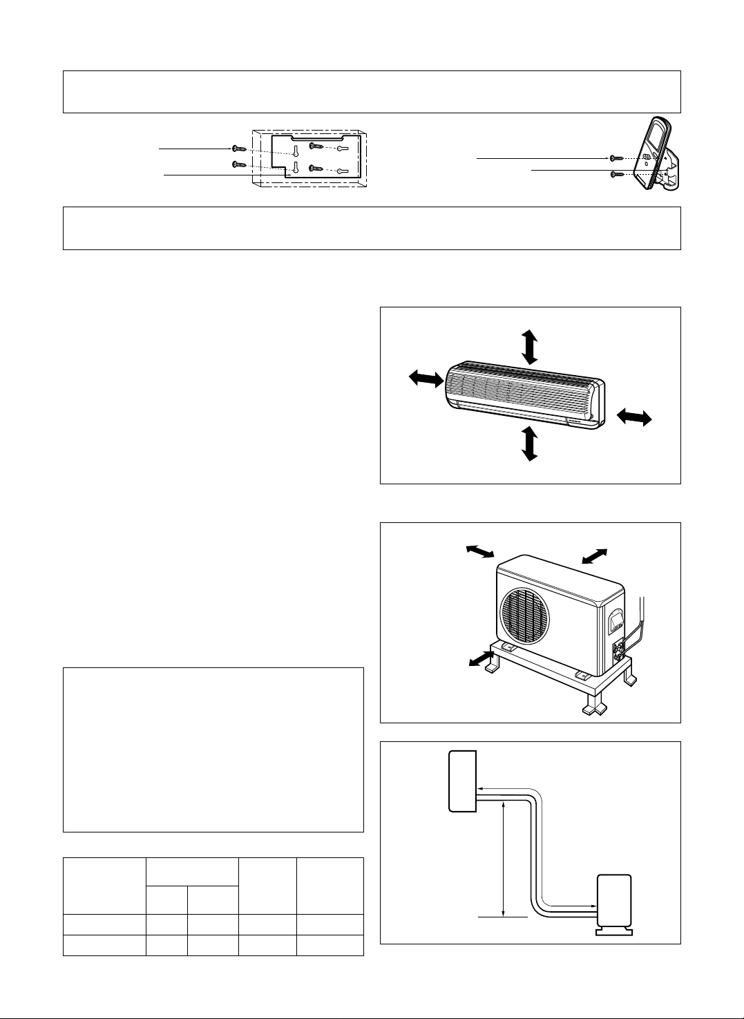
1) Selection of the best location
1. Indoor unit.
2. Outdoor unit.
3.Piping length and the elevation
• There should not be any heat source or
steam near the unit.
• There should not be any obstacles to prevent
the air circulation.
• A place where air circulation in the room will be good.
• A place where drainage can be easily obtained.
• A place where noise prevention is taken into
consideration.
• Do not install the unit near the door way.
• Ensure the spaces indicated by arrows from
the wall, ceiling, fence, or other obstacles.
• If an awning is built over the unit to prevent
direct sunlight or rain exposure, be careful
that heat radiation from the condenser is not
restricted.
• There should not be any animals or plants
which could be affected by hot air discharged.
• Ensure the spaces indicated by arrows from
the wall, ceiling, fence, or other obstacles.
More than
5 cm(2")
More than 5 cm(2")
More than
5 cm(2")
More than eye level
More than 10 cm(4")
More than 10 cm(4")
More than 70 cm(28")
Indoor unit
Outdoor
unit
Pipe Size
MODEL
(Cooling Capa.)
GAS LIQUID
Max.
length
A
Max.
Elevation
B
9K, 12K 1/2" 1/4" 15m(50ft) 8m(26ft)
18K, 24K 5/8" 3/8" 15m(50ft) 8m(26ft)
1. Type "A" screw
3. Type "B" screw
4. Holder Remote-Controller
2. Installation Plate
Roof Top Installations
If it is necessary to install units on a roof
structure, be sure to elevate and level the units.
Ensure the roof structure and anchoring method
are adequate for unit location. Consult local
codes regarding rooftop mounting.
NOTE: When condensing unit is to be installed on
a bonded guaranted roof, a release must
be obtained from the building owner to
free the installer from all liabilities.
B
A
Page 4
Avoid areas where electrical wiring,
conduits or gas lines are located.
Accidentally cutting a live wire or gas
line can cause death or injury.
4
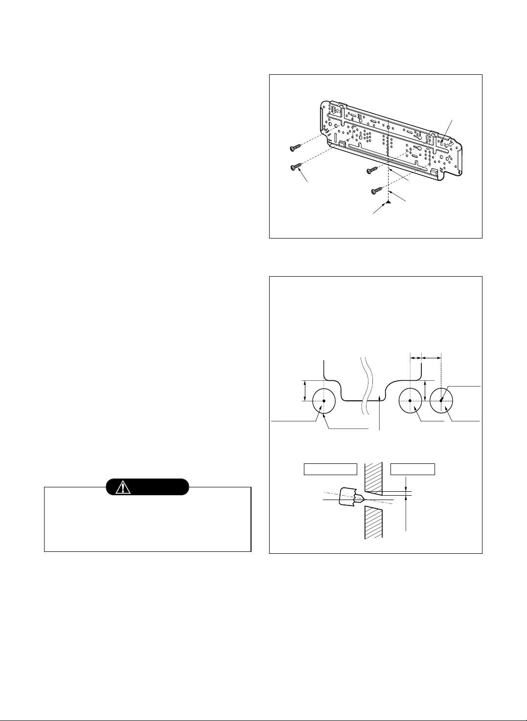
2) Indoor Unit Installation
The mounting wall should be strong and solid
enough to protect it from the vibration.
1.Mount the installation plate on the wall
with four Type "A" screws.
(if mounting the unit on the concrete wall,
consider using anchor bolts.)
• Always mount the Installation Plate
horizontally by aligning the marking-off line
by means of the thread and a level.
2. Drill the piping hole with 70mm(2.75") dia.
holecore drill.
• See templates in the back of this
manual(page 19, 20) for hole location
relative to the installation plate.
• Drill the Piping hole at either the right or the
left and the hole should be slightly slanted
to the outdoor side.
Type "A" screw
Installation Plate
marking-off line
Thread
Weight
The lower left and right side of Installation
Plate
WARNING
Left rear piping
1.8"
(46mm)
Right rear piping
1"
(25mm)2"(51mm)
1.9"
(48mm)
Hole center
9K, 12K, 18K, 24K
ø2.75"(70mm)
INDOOR
Installation plate
WALL
OUTDOOR
5-7mm
9K,12K
(0.2~0.3")
18K, 24K
Page 5
5
3. Piping and Drainage of Indoor Unit
1) Preparation of pipings
1. Cut the pipes and the cable.
• Use the pipes purchased locally.
• Measure the distance between the indoor
and the outdoor unit.
• Cut the pipes a little longer than measured
distance.
• Cut the cable 1.5m(5.0 ft) longer than the
length of the pipe.
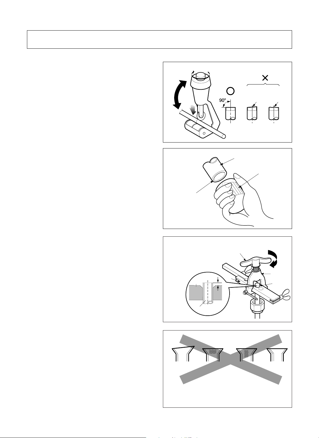
2. Remove burrs.
• Remove burrs from cut edges of pipes.
• Turn the pipe end toward down to avoid the
metal powder entering the pipe.
Caution:
If burrs are not removed, they may cause a gas
leakage.
3. Flaring the pipes.
• Insert the flare nuts, mounted on the
connection ports of both indoor and outdoor
unit, onto the copper pipes. Some gas may
leak, when the flare nuts are removed from
the indoor unit, as some gas is charged to
prevent the inside of the pipe from rusting.
• Fit the copper pipe end into the Bar of flare
tool about 0.5~1.0mm higher. (See
illustration)
• Make a flare at the end of copper pipe with a
flare tool*.
* Use "RIDGID" or equivalent.
4. Tape the flaring portion to protect it from
the dust or damages.
Bar
Yoke
Cone
Handle
Ä
Bar
Copper pipe
When properly flared, the internal surface of the
flare will evenly shine and be of even thickness.
After the flare part comes into contact with the
connectors, carefully check the flare finish.
Pipe cutter
Slanted
Rough
Pipe
Point down
Reamer
"
A"; ø6.35mm (1/4") ¡ 0.5mm
ø9.52mm (3/8") ¡ 0.5 mm
ø12.7mm (1/2") ¡ 0.5 mm
ø15.88mm (5/8") ¡ 1.0mm
= Improper flaring =
Inclined
Surface
damaged
Cracked
Uneven
thickness
Page 6
If the drain hose will run in the room,
insulate the hose with an insulation
material* so that dripping from
"sweating"(condensation) will not damage
furniture or floors.
* Foamed polyethylene or equivalent is
recommended.
6
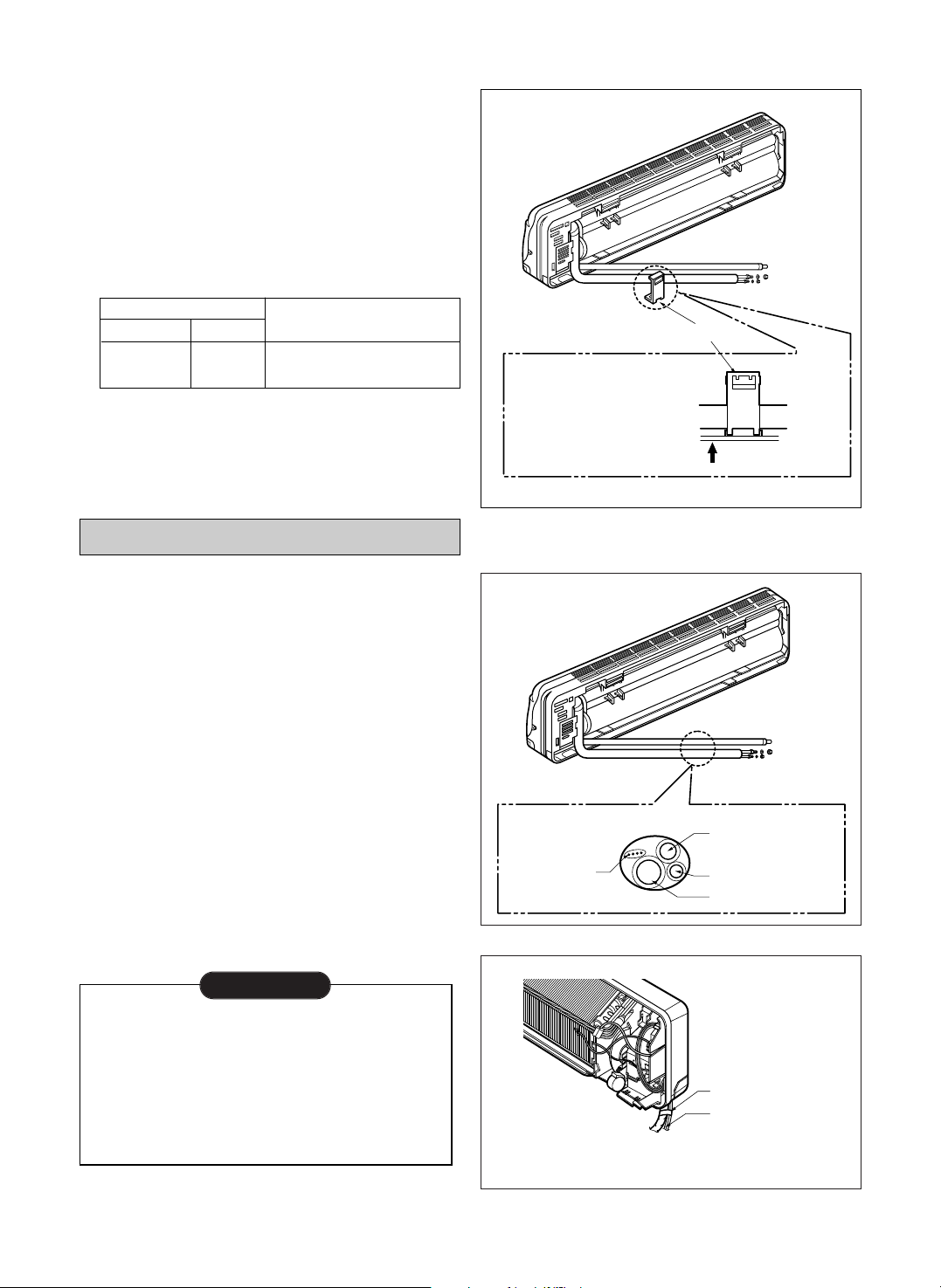
2) Connection of Pipings
1. Remove the indoor tubing with Drain hose
from the hole
• Remove tubing holder and pull the tubing out
of the chassis.
2. Replace the tubing holder into original position.
• Recommended SPEC. of the additional Drain
Hose.
*
Foamed Polyethylene or equivalent is
recommended.
CAUTION: The unit's drain hose and additional
drain hose must be sealed up by
adhesive or tape.
For right rear piping
3. Route the tubing and the drain hose
straight backwards.
4. Insert the connecting cable into the indoor
unit through the piping hole.
• Do not connect the cable to the indoor unit.
• Make a small loop with the cable for easy
connection later.
5. Tape the tubing, drain hose and the
connecting cable. Be sure that drain hose
locates at the lowest side of the bundle.
Locating at the upper side can be a reason
that drain water overflows drain pan inside
the unit.
¤ŁPull
¤ Press
To remove the holder,
press the bottom of
chassis near the holder
upward and pull the tab
out of its hole.
Tubing holder
Connecting
cable
Gas side piping
Liquid side piping
Drain hose
Taping
Indoor/Outdoor
Connecting cable
NOTE
Joint Part
The material of Drain hose
Inner size Material
MAX.
ø16mm(5/8")
soft PVC
Soft PVC hose
(It must be surrounded with an Insulation Material
*
)
Page 7

7
6. Indoor unit installation
• Hook the indoor unit onto the upper portion
of installation plate. (Engage the two hooks
of the rear top of the indoor unit with the
upper edge of the installation plate.)
Ensure the hooks are properly seated on the
installation plate by moving it left and right.
7. Connecting the pipings to the indoor unit.
• Align the center of the pipings and sufficiently
tighten the flare nut with fingers.
• Finally, tighten the flare nut with torque
wrench until the wrench clicks.
When tightening the flare nut with torque
wrench, ensure the direction for tightening
follows the arrow on the wrench.
8. Wrap the insulation material around the
connecting portion.
CAUTION: Take care to arrange the pipings,
drain hose and cables as the
picture on page 6 for inserting it
into the indoor unit and refixing
the tubing holder easily.
9. Insulation of connecting tubing
• Because capillary tubing is installed in the
outdoor unit, both the liquid and gas side
tubes of this air conditioner become cold or
hot(Heat pump model).
Therefore, to prevent heat loss and wet
floors due to dripping of condensation water,
both tubes must be well insulated with proper
insulation material.
The thickness of the insulation material
should be a Min. 8mm(5/16").
Connecting
cable
Drain hose
Press the lower left and right side of the unit
against the Installation Plate until the hooks
engage with their slots (sound click).
Model
Pipe Size Torque
9K,
Liquid Side (1/4") 1.8kg¡⁄m(13.0ft.lbs)
12K
Gas Side (1/2") 5.5kg¡⁄m(39.8ft.lbs)
18K,
Liquid Side (3/8") 4.0kg¡⁄m(28.9ft.lbs)
24K
Gas Side (5/8") 6.6kg¡⁄m(47.7ft.lbs)
Flare nut
Pipings
Torque wrench
Spanner
Indoor unit tubing
Plastic Bands
Insulation material
Wrap the insulation material around the
connecting portion.
Min. 8mm
(5/16")
Min. 8mm
(5/16")
Insulation
Thickness.
For Heat pump model, Heat-resistant
insulation material enduring at 230°F should
be used.
Page 8

8
For the left pipings
3. Route the indoor tubing with the drain hose
to the piping hole as desired position.
4. Insert the pipings, power supply cord and
connecting cable into the piping hole.
Indoor
Outdoor
Connecting cable
Piping
¤ŁPull
To remove the holder,
press the bottom of
chassis near the holder
upward and pull the tab
out of its hole.
Tubing holder
¤ Press
Page 9

9
5. Insert the connecting cable into the indoor
unit.
• Don't connect the cable to the indoor unit.
• Make a small loop with the cable for easy
connection later.
6. Tape the tubing, drain hose and the
connecting cable.
7. Indoor unit installation
• Hook the indoor unit onto the upper portion
of installation plate. (Engage the two hooks
of the rear top of the indoor unit with the
upper edge of the installation plate.)
Ensure the hooks are properly seated on the
installation plate by moving it in left and right.
8. Connecting the pipings to the indoor unit.
• Align the center of the pipings and sufficiently
tighten the flare nut with fingers.
• Finally, tighten the flare nut with torque
wrench until the wrench clicks.
When tightening the flare nut with torque
wrench, ensure the direction for tightening
follows the arrow on the wrench.
Indoor/outdoor
connecting cable
Connecting
cable
Taping
Gas side piping
Liquid side piping
Drain hose
Flare nut
Pipings
Torque wrench
Spanner
Indoor unit tubing
Plastic Bands
Insulation material
Wrap the insulation material around the
connecting portion.
9. Wrap the insulation material around the
connecting portion.
CAUTION: Take care to arrange the pipings,
drain hose and cables as the right
upper picture for inserting it into
the indoor unit and refixing the
tubing holder easily.
Model
Pipe Size Torque
9K,
Liquid Side (1/4") 1.8kg¡⁄m(13.0ft.lbs)
12K
Gas Side (1/2") 5.5kg¡⁄m(39.8ft.lbs)
18K,
Liquid Side (3/8") 4.0kg¡⁄m(28.9ft.lbs)
24K
Gas Side (5/8") 6.6kg¡⁄m(47.7ft.lbs)
Page 10

10
10. Set the pipings and the connecting cable
to the back of the chassis with the tubing
holder
• Hook the edge of tubing holder to tap on
chassis and push the bottom of tubing holder
to be engaged in the bottom of chassis.
11. Indoor unit installation
• Hook the indoor unit onto the upper portion
of installation plate. (Engage the two hooks
of the rear top of the indoor unit with the
upper edge of the installation plate.)
Ensure the hooks are properly seated on the
installation plate by moving it in left and right.
Piping
Taping
Drain hose
Tubing holder
¤ Hook
¤ŁPush
Connecting
cable
Drain hose
Press the lower left and right side of the unit
against the Installation Plate until the lower hooks
engage with their slots (sound click).
Page 11

2)
Connection of the cable
1. Remove the cover control from the unit by
loosening the 3 screws.
2. Dismount caps on the conduit panel.
3. Temporarily mount the conduit tubes on the
conduit panel.
4. Properly connect both the power supply and low
voltage lines to the corresponding terminals on
the terminal block.
5. Ground the unit in accordance with local codes.
6. Be sure to size each wire allowing several inches
longer than the required length for wiring.
7. Use lock nuts to secure the conduit tubes.
11
4. Connecting Pipings and the cable to Outdoor unit
1) Connecting the pipings to the
Outdoor unit
1. Align the center of the pipings and
sufficiently tighten the flare nut with fingers.
2. Finally, tighten the flare nut with torque
wrench until the wrench clicks.
• When tightening the flare nut with torque
wrench, ensure the direction for tightening
follows the arrow on the wrench.
Outdoor unit
Outdoor unit
Gas side piping
(Bigger Dia.)
Liquid side piping
(Smaller Dia.)
Torque wrench
High Voltage
Terminal block
Connecting
cable
Conduit panel
Power supply
cord
Cover control
Over
5mm(2")
Connector trade size for this unit is 1/2".
Refer to "How to connect wiring to the terminals" for
instructions on connecting depending on the wire
type you are using.
NOTE
1. shows field wiring.
2. Separately wire the high and low voltage line.
3. Use heat-proof electrical wiring capable of withstanding
temperatures up to 167°F.
4. Use outdoor and waterproof connection cable rated more than 300V
for the connection between indoor and outdoor unit.
(For example, Type SJO-WA)
NOTE
• Be sure to comply with local codes while running the
wire from the indoor unit to the outdoor unit(size of
wire and wiring method, etc).
• Every wire must be connected firmly.
• No wire should be allowed to touch refrigerant tubing,
the compressor or any moving parts.
WARNING
Power Supply
Model Power source
9K,12K 1ø, 115V 14 18 20A
18K 1ø, 230/208V 14 18 15A
24K 1ø, 230/208V 14 18 20A
AWG(MIN.)
¤˝ ¤˛
Fuse or breaker
Capacity
1
Indoor Unit Outdoor Unit
2
3
4
1
2
3
4
5
6
G
To
branch
circuit
Ground
Power supply
a
L1
L2
Connecting cable(Low voltage)
b
Terminal
(4P)
Terminal
(6P)
Wiring Diagram
Model
Pipe Size Torque
9K,
Liquid Side (1/4") 1.8kg¡⁄m(13.0ft.lbs)
12K
Gas Side (1/2") 5.5kg¡⁄m(39.8ft.lbs)
18K,
Liquid Side (3/8") 4.0kg¡⁄m(28.9ft.lbs)
24K
Gas Side (5/8") 6.6kg¡⁄m(47.7ft.lbs)
Page 12

12
Connection method of the connecting cable(Example)
(1) Dismount two-caps on the conduit panel.
(2) Make a hole appropriate for the passage of
connection cable through on cap by tool.
(for low voltage line)
(3) Pass the connecting cable through the hole.
(4) Properly connect the cable on the terminal block.
(5) Fix the connection cable with clamp cord
provided on the unit not to have strain at the
terminal when the connection cable is pulled
outside up to a 35 pound weight.
(6) Wind the vinyl tape round the connecting
cable for sealing between the surface of the
connection cable and cap.
(7) Mount the taped part of cable on the cap.
(8) Finally, mount the holed cap with the wound
cable on the conduit panel.
When connecting each power wire to the
corresponding terminal, follow instructions "How to
connect wiring to the terminals" and fasten the wire
tightly with the fixing screw of the terminal plate.
How to connect wiring to the terminals
§ For solid core wiring (or F-cable)
(1) Cut the wire end with a wire cutter of
wire-cutting pliers, then strip the insulation to
expose the solid wire about 25mm(15/16")
(2) Using a screwdriver, remove the terminal
screw(s) on the terminal plate.
(3) Using pliers, bend the solid wire to from a
loop suitable for the terminal screw.
(4) Shape the loop wire properly, place it on the
terminal plater and tighten securely with the
terminal screw using a screwdriver.
§ For strand wiring
(1) Cut the wire end with a wire cutter or
wire-cutting pliers, then strip the insulation to
expose the strand wiring about 10mm(3/8").
(2) Using a screwdriver, remove the terminal
screw(s) on the terminal plate.
(3) Using a round terminal fastener or pliers,
securely clamp each stripped wire end with a
round terminal.
(4) Position the round terminal wire, and replace and
tighten the terminal screw using a screwdriver.
Loose wiring may cause the terminal to overheat
or result in unit malfunction. A fire hazard may
also exist. Therefore, be sure all wiring is tightly
connected.
WARNING
G
Terminal
block
Cap
(Remove)
Clamp cord
Lock nut
Conduit panel
Loop
Round
terminal
Screw with
special washer
Screw with
special washer
Round terminal
Terminal plate
Wire
Wire
Round terminal
Insulation
Strip 25mm(15/16")
Strip 10mm(3/8")
Solid wire
Cap(Reuse)
Taping
(for sealing)
Low voltage line
(connecting cable)
Power supply line
(1ø, 230/208V)
Hole
(for low voltage line)
Strand wire
Page 13

13
1) Checking the Drainage
1. Remove the Grille from the cabinet.
• Set the up-and-down air direction louver to
open position (horizontally) by finger
pressure.
• Remove 3 screws.
• To remove the Grille, pull lower the left and
right side of the grille toward you (slightly
tilted) and lift it straight upward (Four tabs on
the top inside edge of chassis are clear of
their slots).
2. Check the drainage.
• Pour a glass of water on the evaporator.
• Ensure if water flows drain hose of indoor
unit without any leakage.
5.
Checking the Drainage and Connecting the cable to Indoor unit
Grille
Chassis
Screw(3 places)
• Outside drain hose should be lower than inside.
• The end of drain hose should not come in touch with
surface of land.
• The end of drain hose should not dip into sewer or
water.
NOTE
Page 14

14
2) Connect the cable to the indoor
unit
1. Connect the wires to the terminals on
the control board individually according
to the outdoor unit connection.
• Ensure that the color of the wires of
outdoor unit and the terminal No. are the
same as those of indoor unit respectively.
(Refer to Wiring diagram on page11.)
Connecting cable
2. Attach the Grille onto the cabinet.
• Grasp lower the left and right side of the
Grille and engage four tabs on the top
inside edge of the chassis.
• Press the Grille toward the chassis until it
will be back into place.
• Be sure to refer to the wiring diagram label
inside the cover control and carry out the
correct field wiring.
Wrong wiring can cause the unit to misoperate
to result in a fire hazard.
• Check local electrical codes and any specified
wiring instructions or limitations.
WARNING
Page 15

15
3) Forming the pipings
1. Wrap the connecting portion of indoor unit
with the Insulation material and secure it
with two Plastic Bands.(for the right
pipings)
• If you want to connect an additional drain
hose, the end of the drain-outlet should keep
distance from the ground.(Do not dip it into
water, and fix it on the wall to avoid swinging
in the wind.)
2. Tape the Pipings, drain hose and
Connecting Cable from down to up.
3. Form the pipings gathered by taping along
the exterior wall and fix it onto the wall by
saddle or equivalent.
2. Tape the Pipings and Connecting cable
from down to up.
3. Form the pipings gathered by taping along
the exterior wall, make the Trap to be
required to prevent water from entering
into the room.
4. Fix the pipings onto the wall by saddle or
equivalent.
In case of the Outdoor unit being installed
below position of the Indoor unit.
In case of the Outdoor unit being installed
above position of the Indoor unit.
Seal a small opening
around the pipings with
gum type sealer.
Taping
Pipings
Connecting
cable
Plastic
band
• Trap is required to prevent water from
entering into electrical parts.
Seal a small opening
around the pipings
with gum type sealer.
Trap
Drain hose
Page 16

16
6. Air Purging
Air and moisture remaining in the refrigerant system
have undesirable effects as indicated below.
• Pressure in the system rises.
• Operating current rises.
• Cooling(or heating) efficiency drops.
• Moisture in the refrigerant circuit may freeze and
block capillary tubing.
• Water may lead to corrossion of parts in the
refrigeration system.
Therefore, the indoor unit and tubing between the
indoor and outdoor unit must be leak tested and
evacuated to remove any noncondensables and
moisture from the system.
1)Air Purging with a Vacuum Pump
§ Preparation
Check that each tube(both liquid and gas side
tubes) between the indoor and outdoor units has
been properly connected and all wiring for the test
run has been completed. Remove the valve caps
from both the gas and the liquid side service
valves on the outdoor unit. Note that both liquid
and gas side service valves on the outdoor unit are
kept closed at this stage.
§ Leak test
1. Connect the manifold valve(with pressure
gauges) and dry nitrogen gas cylinder to this
service port with charge hoses.
CAUTION: Be sure to use a manifold valve for air
purging. If it is not available, use a stop valve
for this purpose. The "Hi" knob of the manifold
valve must always be kept close.
2. Pressurize the system to no more than 150 P.S.I.G
with dry nitrogen gas and close the cylinder valve
when the gauge reading reached 150 P.S.I.G. Next,
test for leaks with liquid soap.
CAUTION: To avoid nitrogen entering the refrigerant
system in a liquid state, the top of the cylinder must
be higher than its bottom when you pressurize the
system. Usually, the cylinder is used in a vertial
standing position.
3. Do a leak test of all joints of the tubing(both indoor
and outdoor) and both gas and liquid side service
valves.
Bubbles indicate a leak. Be sure to wipe off the
soap with a clean cloth.
4. After the system is found to be free of leaks, relieve
the nitrogen pressure by loosening the charge hose
connnector at the nitrogen cylinder. When the
system pressure is reduced to normal, disconnect
the hose from the cylinder.
Lo Hi
Indoor unit
Outdoor unit
Manifold valve
Charge hose
Nitrogen gas
cylinder
(in vertical
standing position)
Pressure
gauge
Page 17

17
§ Evacuation
1. Connect the charge hose end described in the
preceding steps to the vacuum pump to
evacuate the tubing and indoor unit.
Confirm the "Lo" knob of the manifold valve is
open. Then, run the vacuum pump.
The operation time for evacuation varied with
the tubing length and capacity of the pump. The
following table shows the amount of time for
evacuation.
Allow the pump to operate until the system has
been evacuated down to 300 microns. Allow the
pump to continue running for an additional 15
minutes. Turn off the pump and leave the
connections secured to the two service valves.
After 5 minutes, if the system fails to hold 500
microns or less, check all connections for tight
fit and repeat the evacuation procedure.
2. When the desired vacuum is reached, close the
"Lo" knob of the manifold valve and stop the
vacuum pump.
§ Finishing the job
1. With a service valve wrench, turn the valve stem
of liquid side valve counter-clockwise to fully
open the valve.
2. Turn the valve stem of gas side valve
counter-clockwise to fully open the valve.
3. Loosen the charge hose connected to the gas side
service port slightly to release the pressure, then
remove the hose.
4. Replace the flare nut and its bonnet on the gas side
service port and fasten the flare nut securely with
an adjustable wrench. This process is very
important to prevent gas leakage from the system.
5. Replace the vlave caps at both gas and liquid side
service valves and fasten them securely tight.
This complete air purging with a vacuum pump. The air
conditoner is now ready to test run.
Lo Hi
Indoor unit
Outdoor unit
Manifold valve
Vacuum pump
Pressure
gauge
Page 18

• Insert two batteries provided.
Remove the battery cover from the remote
controller.
• Slide the cover according to the arrow
direction.
Insert the two batteries.
(Two "R03" or "AAA" dry-cell batteries or
equivalent.)
• Be sure that the (+) and (-) directions are
correct.
• Be sure that both batteries are new.
Re-attach the cover.
• Slide it back into position.
(3) Turn on the power and run the unit.
18
7. Test running
Settlement of Outdoor Unit
Prepare to Remote Control
• Anchor the outdoor unit with a bolt and nut
(ø10cm) tightly and horizontally on a
concrete or rigid mount.
• When installing on the wall, roof or rooftop,
anchor the mounting base securely with a
nail or wire assuming the influence of wind
and earthquake.
• In the case when the vibration of the unit is
conveyed to the house, settle the unit with an
anti-vibration rubber.
Bolt
Tubing connection
(1) Check that all tubing and wiring have been properly connected.
(2) Check that the gas and liquid side service valves are fully open.
Evaluation of the performance
Operate unit for 15~20 minutes, then check the system refrigerant charge:
(1) Measure the pressure of the gas side service valve.
(2) Measure the outside ambient air temperature.
(3) For reference; the gas side pressure of optimum condition is as below;
NOTE:
If the actual pressure are higher than shown, the system is most likely over-charged, and
charge should be removed. If the actual pressure are lower than shown, the system is most
likely undercharged, and charge should be added.
The air conditioner is now ready for actual operation.
Outside ambient TEMP. The Pressure of the gas side service valve
35°C(95°F) 4~5kg/cm2(56.8~71.0 P.S.I.G)
RESET
RESET
RESET
Page 19

19
8. Installation Instruction Templates
Left Side Installation
Piping hole
Ø2
3
/
4
"
Installation Plate
1.8"
Page 20

20
Right Side Installation
Models 9K 18K
12K 24K
1"
2"
Piping hole
Ø2
3
/
4
"
Piping hole
Ø2
3
/
4
"
1.9"
Installation Plate
 Loading...