

LG KG200 - Cell Phone 60 MB Service Manual

Date: November, 2006 / Issue 1.0
Service Manual
Model : KG200
Service Manual
KG200
KG200 cover(4)_1109 2006.11.10 3:18 PM ˘`1

- 3 -
1. Introduction and Specification .................................................5
2. Software Download Procedure...............................................11
3. Assembly and Disassembly ...................................................18
4. Troubleshooting.......................................................................22
5. CIRCUIT DIAGRAMS................................................................55
6. PCB LAYOUT............................................................................71
7. EXPLODED VIEW & REPLACEMENT PART LIST..................73
Contents

- 4 -

1. INTRODUCTION
- 5 -
1.1 Unit SPECIFICATION
1. INTRODUCTION
7330
RTP Sep/ M, 2006
Solution 6226M
Type Bar type
Antenna Type Internal( tri-Band)
Main Display 1,8" 128x160
GPRS Yes, Class 10
MMS Yes, 1.1
Camera Change to 1.3 M
Battery 800 mAh
Audio player--real resuming Yes
FM Receiver Yes
MPEG4/H.263 Yes
H.264 No
AAC+ No
FM as alarm Yes
Scheduled FM recording Yes
MP4 for incoming call/ power on off
Yes
animation and screen saver
Speaker Yes, single speaker
Audio player--real resuming Yes

1. INTRODUCTION
- 6 -
Video recording Yes
Memory Size 128Mb flash + 32Mb Ram
Internal NAND 64MB
Memory Card MicroSD
Bluetooth No
USB Yes, slave 1.1
IrMC No
WAP Yes, 2.0
Java No
PoC No
EMAIL No
Status LED with one color Yes
DRM No, OMA 1.0
Dictionary No
MPEG4 caller ID Yes
Finger handwriting No
Touch Panel No
OTA Yes
AB repeat Yes
Music Equalizer Yes
Image Editing No
In flight mode Yes

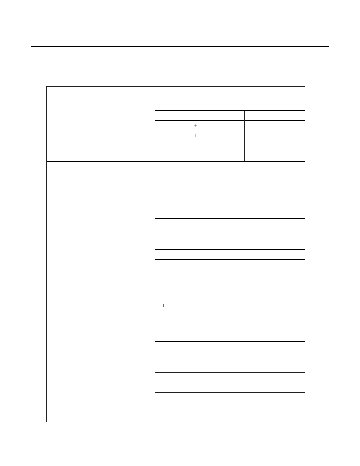
1.2 PERFORMANCE
PRODUCT SPECIFICATION
1. INTRODUCTION
- 7 -
NO NAME SPECIFICATION
EGSM900 Band
TX: 890+n*0.2 MHz
RX: 935+n*0.2 MHz (n= 0~124)
TX: 890+(n-1024)*0.2 MHz
1Frequency Band
RX: 935+(n-1024)*0.2 MHz (n= 975~1023)
DCS1800 Band
TX: 1710+(n-512)*0.2 MHz
RX: 1805+(n-512)*0.2 MHz (n= 512~885)
PCS1900 Band
TX: 1850.2+(n-512)*0.2 MHz
RX: 1930.2+(n-512)*0.2 MHz (n= 512~810)
2 Phase Error
RMS < 5 degrees
Peak < 20 degrees
EGSM900: < 0.1ppm (90 Hz)
3 Frequency Error DCS: < 0.1ppm (180 Hz)
PCS: < 0.1ppm (190 Hz)

1. INTRODUCTION
- 8 -
4 Transmit Power EGSM900
Control Level Power Level Tolerance
5(high) 33 dBm 2dB
6 31 dBm 3dB
7 29 dBm 3dB
8 27 dBm 3dB
9 25 dBm 3dB
10 23 dBm 3dB
11 21 dBm 3dB
12 19 dBm 3dB
13 17 dBm 3dB
14 15 dBm 3dB
15 13 dBm 3dB
16 11 dBm 5dB
17 9 dBm 5dB
18 7 dBm 5dB
19(low) 5 dBm 5dB
DCS1800/PCS1900
Control Level Power Level Tolerance
0(high) 30 dBm 2dB
1 28 dBm 3dB
2 26 dBm 3dB
3 24 dBm 3dB
4 22 dBm 3dB
5 20 dBm 3dB
6 18 dBm 3dB
7 16 dBm 3dB
8 14 dBm 3dB
9 12 dBm 4dB
10 10 dBm 4dB
11 8 dBm 4dB
12 6 dBm 4dB
13 4 dBm 4dB
14 2 dBm 5dB
15 0 dBm 5dB

1. INTRODUCTION
- 9 -
Item Description Specification
EGSM900
OFFSET from Carrier (KHz) Max. (dBm)
100 +0.5
200 -30
250 -33
400 -60
600~ < 1,200 -60
1,200~ < 1,800 -60
1,800~ < 3,000 -63
3,000~ < 6,000 -65
5 Spectrum due to modulation ≥ 6,000 -71
DCS1800/PCS1900
OFFSET from Carrier (KHz) Max. (dBm)
100 +0.5
200 -30
250 -33
400 -60
600~ < 1,200 -60
1,200~ < 1,800 -60
1,800~ < 3,000 -65
3,000~ < 6,000 -65
≥ 6,000 -73
EGSM900
OFFSET from Carrier (KHz) Max. (dBm)
Spectrum due to switching 400 -19
6
transient 600 -21
1,200 -21
1,800 -24
1. INTRODUCTION
- 10 -
Item Description Specification
DCS1800/PCS1900
OFFSET from Carrier (KHz) Max. (dBm)
Spectrum due to switching 400 -22
6
transient 600 -24
1,200 -24
1,800 -27
EGSM900
7 Bit Error Rate
BER (Class II) < 2% @ -105dBm
DCS/PCS
BER (Class II) < 2% @ -103dBm
8 SLR(Sending Loudness Ratio) 8 +/- 3 dB
Frequency (Hz) Max.(dB) Min.(dB)
100 -12 -
200 0 -
300 0 -12
9 Sending Response 1,000 0 -6
2,000 4 -6
3,000 4 -6
3,400 4 -9
4,000 0 -
10 RLR(Receiver Loudness Ratio) 2 3 dB
Frequency (Hz) Max.(dB) Min.(dB)
100 -12 -
200 0 -
300 2 -7
500
*
-5
11 Receiving Response 1,000 0 -5
3,000 2 -5
3,400 2 -10
4,000 2
*
Mean that adopt a straight line in between 300Hz &
1000Hz to be Max. Level in the range.

2. Software Download Procedure
- 11 -
Tools
1. Download cable
2. PC
3. Battery (3.8 V Li-ion Battery)
How to user Leo download tool
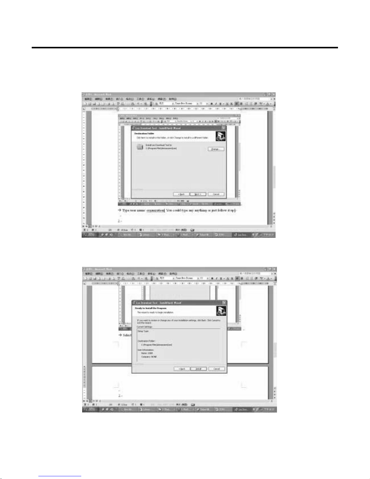
2.1 Install Leo Download tool
➜ Choose I accept the terms in the license agreement
➜ Type user name / organization. [You could type any anything or just follow it up]
2. Software Download Procedure
2. Software Download Procedure
- 12 -
➜ Select default folder
➜ Press Install

2. Software Download Procedure
- 13 -
➜ Press Finish
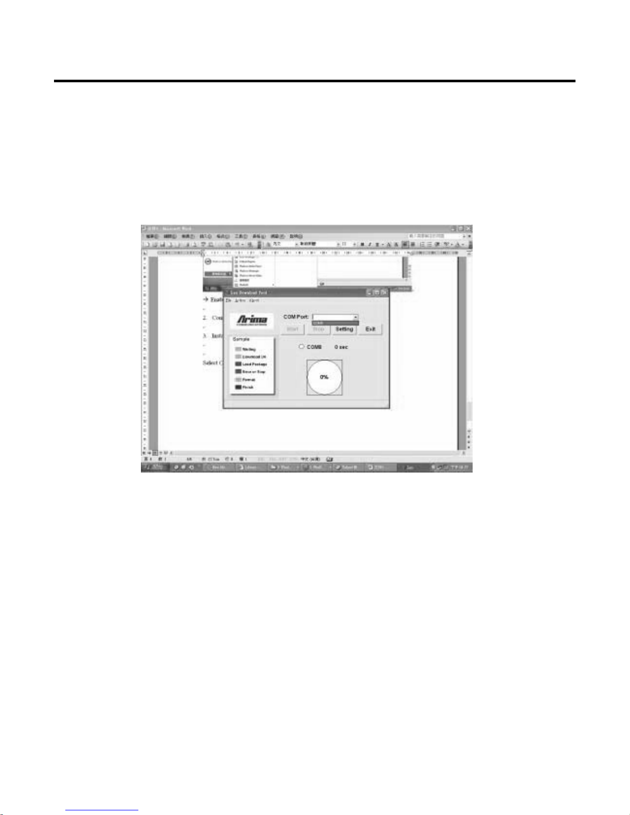
➜ Enable Leo Download tool
2. Software Download Procedure
- 14 -
2.2 Connect Download cable with computer and mobile
2.3 Install SW
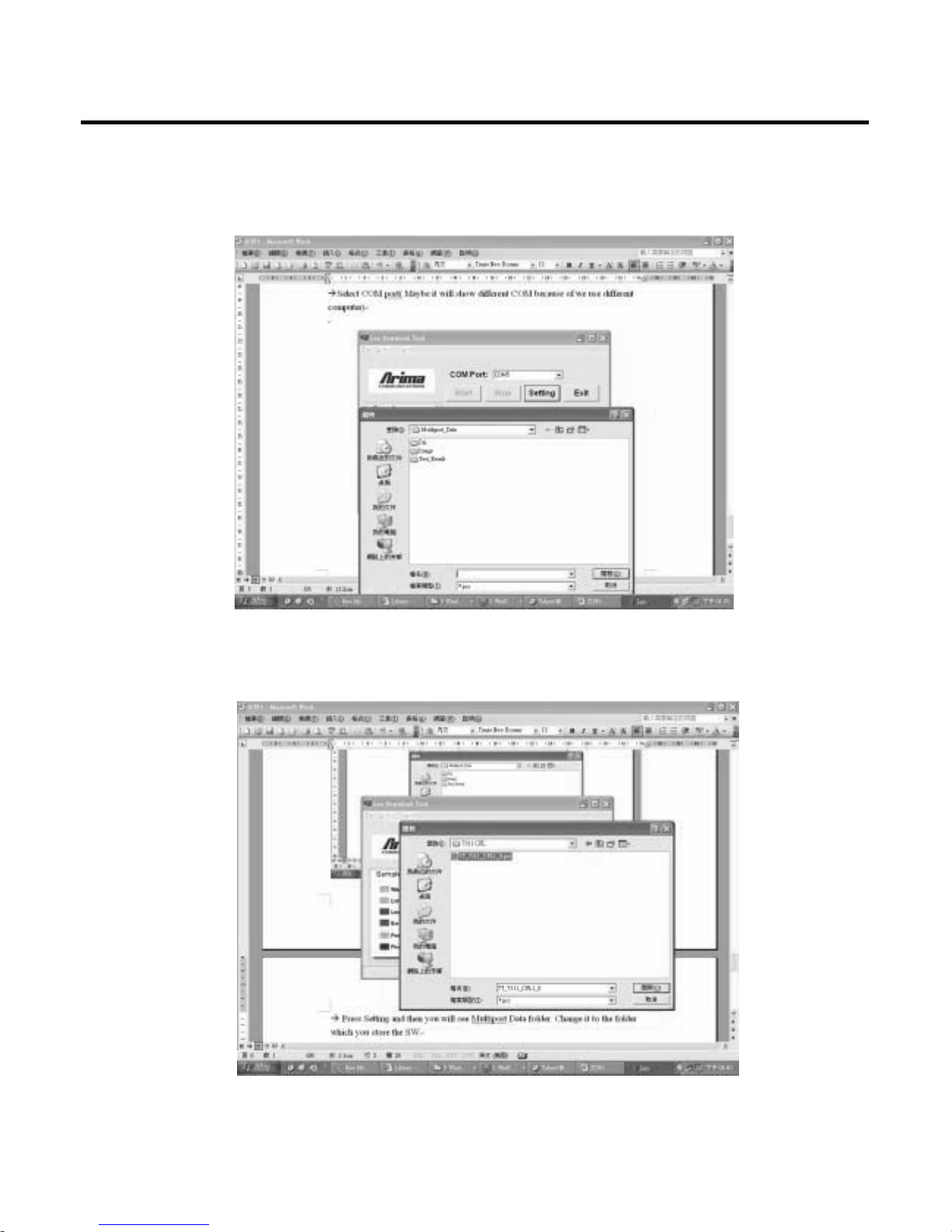
➜ Select COM port (Maybe it will show different COM because of we use different computer)
2. Software Download Procedure
- 15 -
➜ Press Setting and then you will see Multiport Data folder. Change it to the folder which you store
the SW.
➜ Select the. Pcs file and press open. After few seconds, you will see below screen.

2. Software Download Procedure
- 16 -
➜ Press Yes
➜ After you see the pink cycle, long press power on key and then you will see below picture.
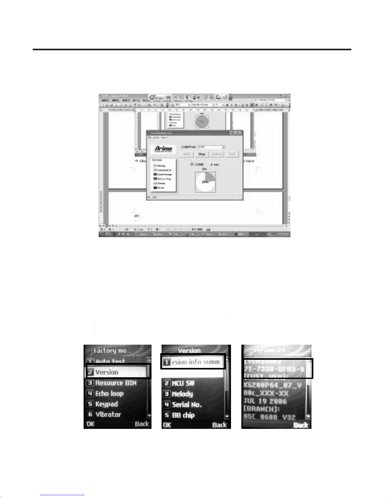
2. Software Download Procedure
- 17 -
➜ After reach to 100%, SW downloads finish.
2.4 Check Software version
2.4.1 Install battery and power on phone.
2.4.2 Press 8 7 8 ( SIM card not installed ) or ✻ # 8 7 8 # ( SIM card installed ) to enter service mode.
2.4.3 Select 2. Version → 1. Summary to check Software Version
2.4.4 Quickly to check SW version: ✻ # 8 3 7 5 #
2.4.5 Quickly to change to English language: ✻ # 0 8 8 6 #
= Send Key
3. Assembly and Disassembly
- 18 -
Tools
* Torque screwdriver, no.6 set
* Pair of tweezers
* Guitar Pick
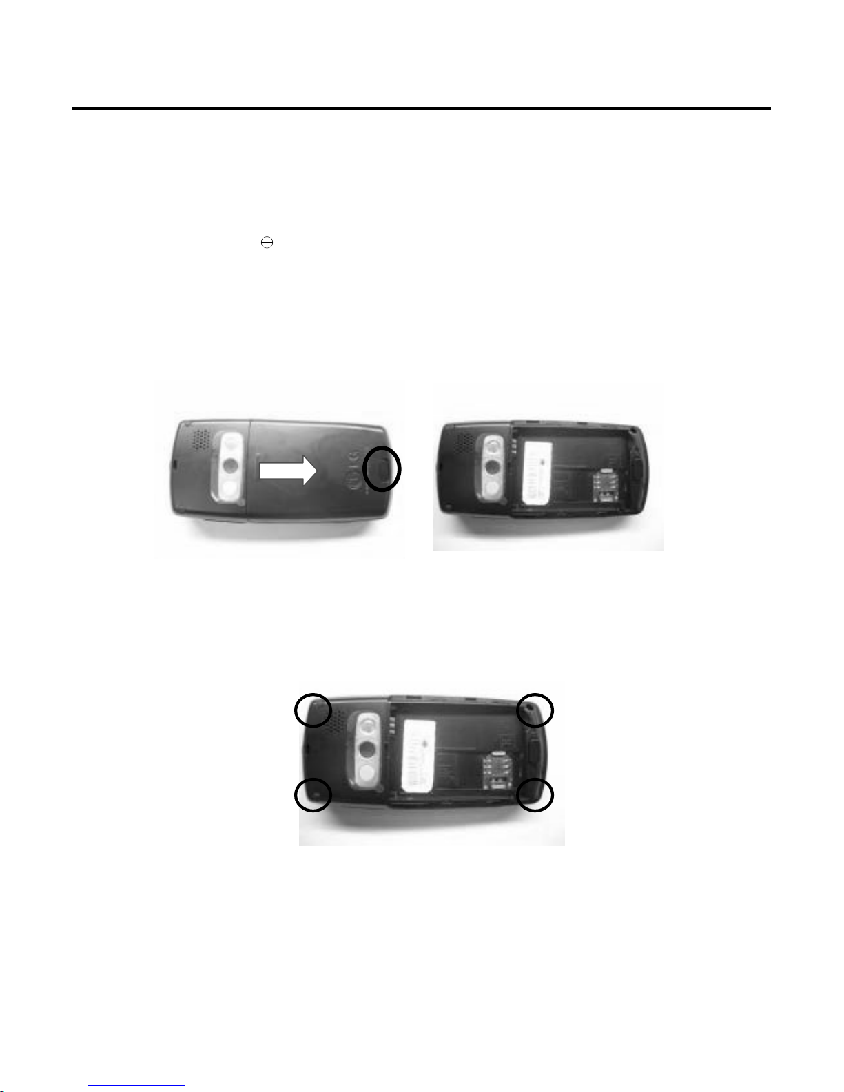
3.1 Disassembly
i. Take off battery cover
ii. Release 4 screws from B-Cover.
3. Assembly and Disassembly
3. Assembly and Disassembly
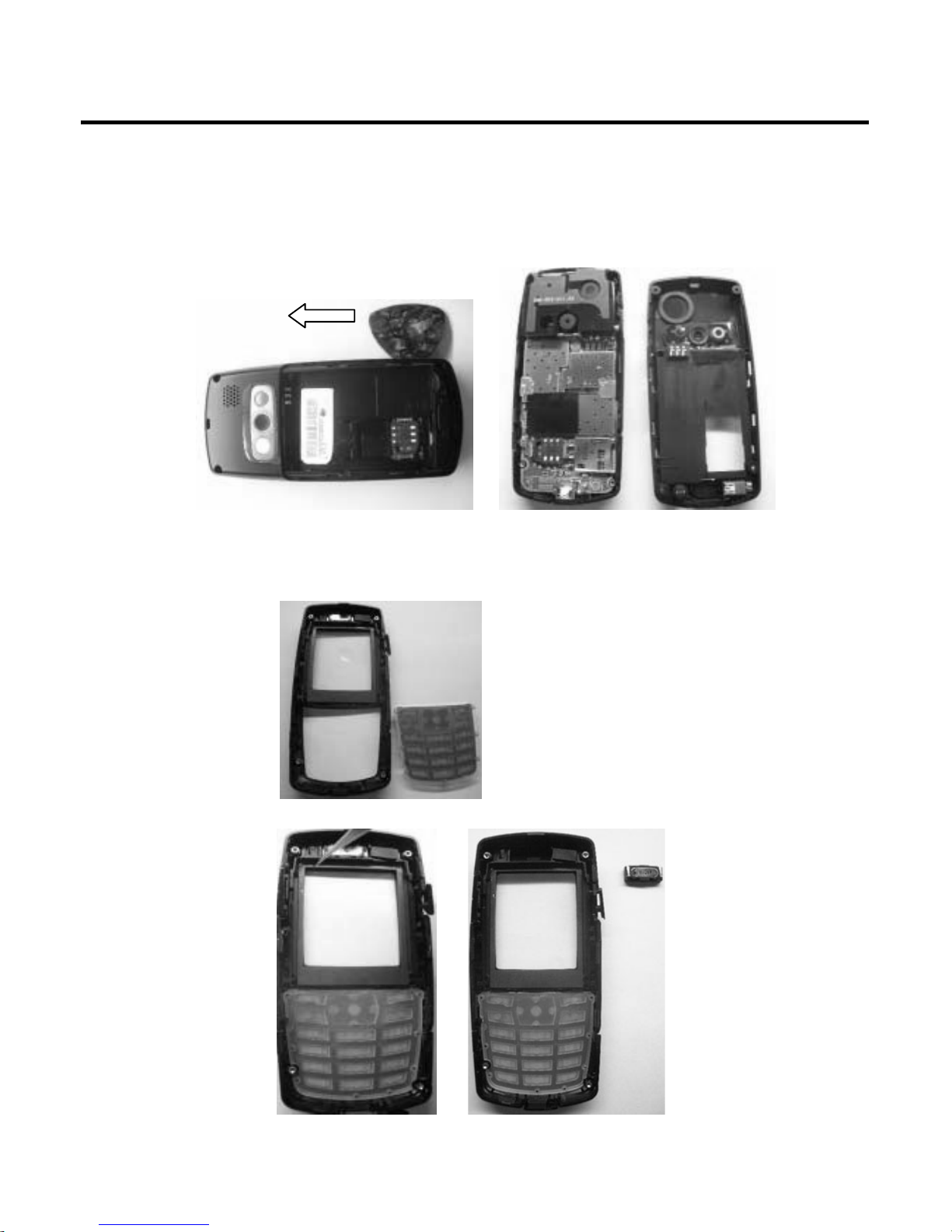
- 19 -
iii. Use the Guitar Pick to take off B-Cover
iv. Remove the Receiver and Key Pad from A-Cover
3. Assembly and Disassembly
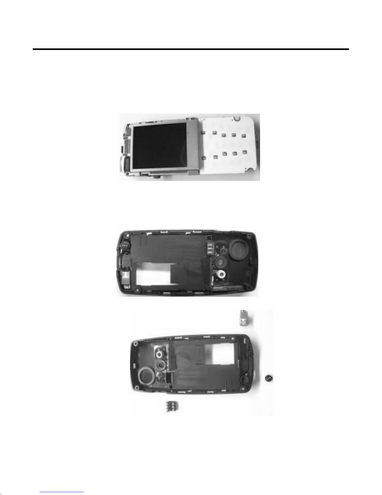
- 20 -
v. Take off the Main Board from B-Cover
vi. Take off the Vibrator, side key, BATT connect and from B-Cover

3. Assembly and Disassembly
- 21 -
vii. Take off the LCM from Main Board
1. Release the LCM connect from Main Board
2. Take off LCM from LCM place.
3.2 Assembly
Please do the reverse steps of disassembly for assembly phone.

4. Troubleshooting
- 22 -
Explanations
The Go / No Go test has to be performed with a mounted phone.
Service function in the software
The service menu will be accessed with the following key combination.
✻ # 8 7 8 # (SIM card in side) or 8 7 8 (No SIM card in side)
In the software of the phone there is a built in service functionality that allows you to test some of the
functions of the phone. This is how it looks:
1. Auto test 12. ADC
2. Version 13. Charger
3. Resource BIN 14. Headset
4. Echo Loop 15. RTC
5. Keypad 16. MTBF
6. Vibrator 17. UART
7. Loud SPK 18. Memory Card
8. Ring Tone 19. Nand Flash
9. LED 20. Camera
10. LCD 21. Total call time
11. Receiver 22. FM Radio
4. Troubleshooting
4. Troubleshooting
- 23 -
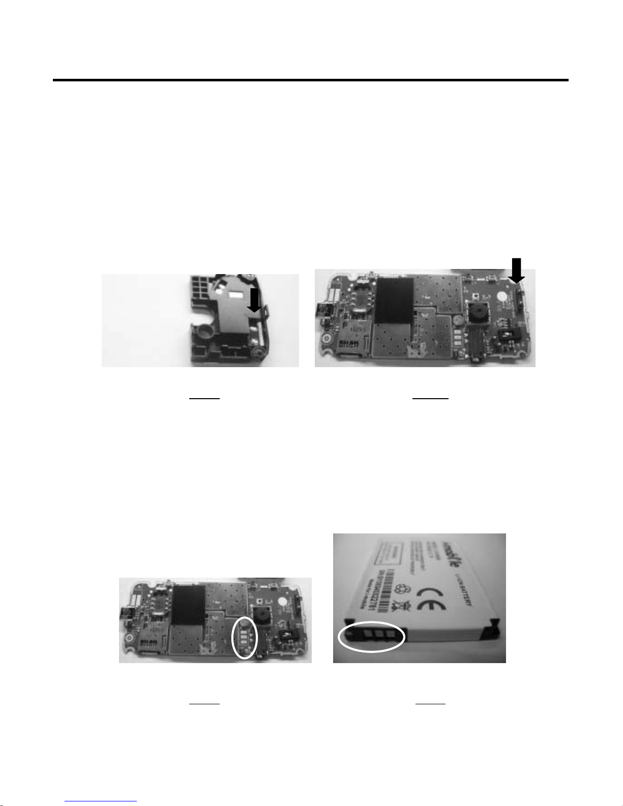
Network Problems
Make a general visual inspection for corrosion or oxidation from liquid damage.
Check that the antenna connects is properly fitted and undamaged (Fig.1.1).
Replace the antenna if necessary.
Check that the antenna Flex Film (Fig 1.2) is not mechanical damaged, dirty or oxidized. Replace it if
necessary.
On/Off problems
Make a general visual inspection for corrosion or oxidation from liquid damage.
Check that the battery pads (Fig.2.1.) are dirty or oxidized. If necessary clean the battery pads.
Check that the Battery (Fig.2.2.) is not mechanical damaged, dirty or oxidized.
Change it if necessary.
Fig 1.1 Figs 1.2
Fig.2.1 Fig.2.2

4. Troubleshooting
- 24 -
Audio problems
Receiver
Turn on the phone. Go to service test menu; choose “11. Receiver” presses any key to check that the
Receiver is working properly.
Check Receiver and receiver cconnector (Fig 3.1)
Microphone
1. Turn on the phone. Go to service test menu; choose “4. Echo Loop” (An audio loop is activated)
check that the Microphone is working properly.
Check that the Microphone Pad (Fig.4.1) is not oxidized or dirty. Clean it if necessary.
Check that the Microphone (Fig.4.2) is not mechanical damaged, dirty or oxidized.
Replace it if necessary.
Fig.3.1
Fig.4.1 Fig.4.2
4. Troubleshooting
- 25 -
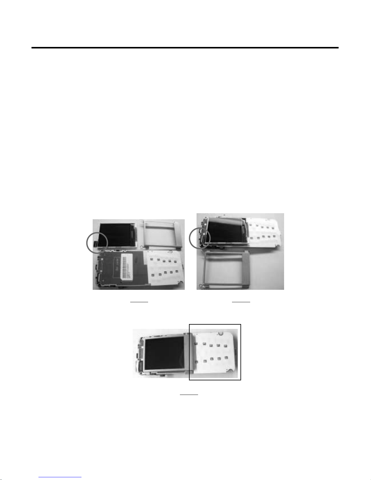
Display/Illumination problems
Make a general visual inspection for corrosion or oxidation from liquid damage.
Turn the phone on. Check the LCD and the illumination. The illumination is lightened when the phone
starts and will continue for approximately 20 sec
Turn the phone on. Go to service test menu; choose “10. LCD” . You should see a pattern check that
no lines or pixels are missing and that there are no discolorations. If necessary replace the LCM.
If all segments are missing check that the LCD connector (Fig.5.1) and LCD FPC (Fig 5.2) is not
mechanical damaged, dirty or oxidized.
Turn the phone on. Go to service test menu; choose “9. LED” . The illumination should start flashing
(Fig 5.3).
Check that all 10 Keypad LEDs have the same illumination strength. If necessary replace the LED
with the weakest light. Repeat this step until all LEDs light ever over the keypad.
Fig.5.1
Fig.5.3
Fig.5.2
 Loading...