

LG K3P-07AS, K3P-07BS, K3P-07CS, MASTER-K200S Datasheet
LG Programmable Logic Controller
MASTER-K200S
CPU Module
K3P-07AS
K3P-07BS
K3P-07CS
●●●●
Beijing Branch
●●●●
Bangkok Branch
LG Industrial Systems LG Industrial Systems (Thailand)
Elevator Co., Ltd. Co., Ltd
T : +86-10-6462-3256 T : +66-2-381-8443
F : +86-10-6462-3255 F : +66-2-381-8445
●●●●
Bogota Branch
●●●●
Chicago Branch
LG Industrial Systems de LG Industrial Systems Co., Ltd.
Colombia S.A. Chicago Office
T : +57-1-310-6077 T : +1-708-692-4500
F : +57-1-310-5831 F : +1-708-692-4501
●●●●
Dalian Branch
●●●●
Hanoi Branch
Dalian LG Industrial Systems LG Industrial Systems Co., Ltd.
Co., Ltd. Hanoi Office
T : +86-411-281-2579 T : +64-4-821-0388
F : +86-411-281-2578 F : +64-4-821-0399
●●●●
Hong Kong Branch
●●●●
Shanghai Branch
LG Industrial Systems (HK) Ltd. Shanghai LG Industrial Systems Co., Ltd.
T : +852-2598-6615 T : +86-21-6248-2710
F : +852-2598-7105 F : +86-216248-3236
●●●●
Singapore Branch
●●●●
Taipei Branch
LG Industrial Systems Co., Ltd. LG Industrial Systems (Taiwan) Co. Ltd.
T : +65-323-7361 T : +886-2-516-5010
F : +65-323-7362 F : +886-2-516-5035
●●●●
Tokyo Branch
LG Industrial Systems Co., Ltd. Tokyo Office
T : +81-3-3589-6362
F : +81-3-3588-1810
LG Industrial Systems Co., Ltd.
●●●●
Head Office
LG Mullae Building 9
th
F, 10, Mullae-dong 6-ga, Yongdungpo-gu, Seoul, KOREA
Tel : +82-2-2006-3751~6 Fax : +82-2-2006-3951
Home page : http:www.lgis.lg.co.kr/fa
702006186
Before handling the product
Read this data sheet carefull y prior to any operation, m ounting, installation or
start-up of the product.
Materials for MASTER-K
Name Code
MASTER-K KGL-WIN (Programming software) 702005036
MASTER-K (Instructions & Programming) 702006539
MASTER-K CPU User’s Manual 702006391
❏❏❏❏
Safety Precautions
Be sure to read carefully the safety precautions given in data sheet and user’s manual before
operating the module and follow them.
The precautions explained here only apply to the MASTER-K 200S CPU module. For safety
precautions on the PLC system, see the MASTER-K CPU User’s manual.
A precaution is given with a hazard alert triangular symbol to call your attention, and
precautions are represented as follows according to the degree of hazard..
!
!
However, a precaution followed with ‘Caution’ can also result in serious conditions.
Both of two symbols indicate that an important content is mentioned, therefore, be sure
to observe it. Keep this manual handy for your quick reference in necessary.
❏❏❏❏
Design Precautions
❏❏❏❏
Installation Precautions
❏❏❏❏
Wiring Precautions
Make sure that FG the terminal is grounded with class 3 grounding which is
dedicated to the PLC. Otherwise, it can cause disorder or malfunction of PLC.
Before the PLC wiring, be sure to check the rated voltage and terminal
arrangement for the module and observe them correctly. If a different power, not of
the rated voltage, is applied or wrong wiring is provided, it can cause a fire or
disorder of the module.
Drive the terminal screws firmly to the defined torque. If loosely driven, it can cause
short circuit, a fire or malfunction.
Be careful that any foreign matter like wire scraps should not enter into the module.
It can cause a fire, disorder or malfunction.
❏❏❏❏
Test RUN and maintenance precautions
❏❏❏❏
Waste Disposal Precaution
This data sheet provides brief information about characteristics, configuration, and usage of
MASTER-K200S CPU modules (K3P-07AS, K3P-07BS, K3P-07CS).
No Item Specifications Standard
1
Operating
temperature
0 ~ 55℃
2
Storage
temperature
-25 ~ 70℃
3
Operating
Humidity
5 ~ 95%RH, non-condensing
4
Storage
humidity
5 ~ 95%RH, non-condensing
Occasional vibration
Frequency Acceleration Amplitude
Sweep
count
10≤f∠57 Hz
- 0.075 mm
57 ≤f≤150 Hz 9.8㎨ {1G}
-
Continuos vibration
Frequency Acceleration Amplitude
10≤f∠57 Hz
- 0.035 mm
5 Vibration
57≤f≤150 Hz 4.9㎨{0.5G}
-
10 times
in each
direction
for
X, Y, Z
IEC 1131-2
6 Shocks
*Maximum shock acceleration: 147㎨ {15G}
*Duration time :11 ms
*Pulse wave: half sine wave pulse
( 3 times in each of X, Y and Z directions )
IEC 1131-2
Square wave
impulse noise
±
1,500 V
Electrostatic
discharge
Voltage :4kV(contact discharge)
IEC 1131-2
IEC 801-2
Radiated
electromagnetic field
27 ~ 500 MHz, 10 V/m
IEC 1131-2
IEC 801-3
Severity
Level
All power
modules
Digital
I/Os
( Ue
≥
24 V)
Digital I/Os
(Ue < 24 V)
Analog I/Os
communication
I/Os
7
Noise
immunity
Fast transient burst
noise
Voltage 2 kV 1 kV 0.25 kV
IEC 1131-2
IEC 801-4
8 Atmosphere Free from corrosive gases and excessive dust
9
Altitude for
use
Up to 2,000m
10
Pollution
degree
2 or lower
11
Cooling
method
Self-cooling
Specifications
Items
K3P-07AS, K3P-07BS, K3P-07CS
Remark
Operation method
Cyclic operation of stored program
Time driven operation, Interrupt operation
I/O control method
Scan synchronized batch processing
method (Refresh method)
Programming Language
Ladder Diagram (LD)
Instruction List (IL)
Basic
instructions
30
Numbers
of
instructions
Application
instructions
218
Execution Time
0.5㎲/step
Program memory capacity 7k steps
Max. I/O points 256 points
P(I/O Relay) P000 ~ P15F (256 points)
M(Auxiliary Relay) M0000 ~ M191F (3,072 points)
K(Keep Relay) K000 ~ K31F (512 points)
L(Link Relay) L000 ~ L63F (1,024 points)
F(Special Relay) F000 ~ F63F (1,024 points)
T(Timer) T000 ~ T255 (256 points)
C(Counter) C000 ~ C255 (256 points)
S(Step Controller) S00.00 ~ S99.99 (100 x 100 steps)
Memory
Device
D(Data Register) D0000 ~ D4999 (5000 words)
Timer (5 type)
On Delay, Off Delay, Integrating, Monos-
table ,Retriggerable
Counter (6 type) Up, Down, Up-Down, Ring
Operation mode RUN,STOP,PAUSE,DEBUG
Self-diagnostic functions
Memory error detection, I/O error detection,
Operation delay monitoring etc.
Internal current consumption 0.17A
Weight (㎏)
0.11
1) Cyclic operation
A PLC program is sequentially executed from the first step to the last step, which is called scan. This
sequential processing is called cyclic operation. Cyclic operation of the PLC continues as long as
conditions do not change for interrupt processing during program execution.
Stages Processing
Operation Start
·Stage for the start of a scan processing. It is executed only
Initialization one time when the power is applied or reset is executed. It
executes the following process.
▶I/O module reset ▶Self diagnosis
▶Data clear ▶I/O module address allocation
·Read input module conditions and store it into the input image
Input image area refresh area before operation processing of a program.
Program operation
·
Program is sequentially executed from the first step to the last
The start of program step.
The end of program
·
The contents stored in the output image area is output to output
Output image area refresh modules when operation processing of a program is finished
·Stage for return processing after the CPU module has finished
END processing 1 scan. The following processing are executed..
▶Self-diagnosis
▶Change of the present values of timer and counter, etc.
▶
Check the status of mode setting switch
2) Time driven interrupt operation method
In time driven interrupt operation method, operations are processed not repeatedly but at every preset
interval. In the K200S CPU module, interval can be set to between 0.01 ~ 600 second. This operation is
used to process operation with a constant cycle
3) Event driven interrupt operation method
If a situation occurs which is requested to be urgently processed during execution of a PLC program,
this operation me thod processes immed iately the operation wh ich corresponds to inter rupt program. The
signal which informs those urgent conditions to the CPU module is called interrupt signal. The K200S
CPU module has two kind of interrupt operation methods, which are internal and external interrupt signal
methods.
If not provided with proper prevention, it can cause death, fatal
injury or considerable loss of property
If not properly observed, it can cause a hazard situation to resul
t
in severe or slight injury or a loss of property.
Don not run I/O signal lines near to high voltage line or power line.
Separate them as 100mm or more as possible. Otherwise, noise can cause module
malfunction.
Operate the PLC in the environment conditions given in the general specifications..
If operated in other environment not specified in the general specifications, it can
cause an electric shock, a fire, malfunction or damage or degradation of the module.
Make sure the module fixing projections is inserted into the module fixing hole and
fixed.
Improper installation of the module can cause malfunction, disorder or falling.
Do not separate the module from the printed circuit board, or do not remodel the
module. They can cause disorder, malfunction, damage of the module or a fire. When
mounting or dismounting the module, perform them after the power has been turned off.
Do not change battery while power is off. It can cause loss of data.
Do not contact the terminals while the power is applied. It can cause malfunction.
When cleaning or driving a terminal screw, perform them after the power has been
turned off.
When disposing the module, do it as an industrial waste.
Caution
Caution
Caution
Warning
Caution
DATA SHEET
1. I
ntroduction
2. G
eneral Spec
ificati
ons
Warning
Caution
3. Perf
ormance Spec
ificati
ons
4. O
peration Processing Method
PLC Others
< Best >
PLC Others PLC Others
< Good > < Bad >
Caution
LG Industrial Systems
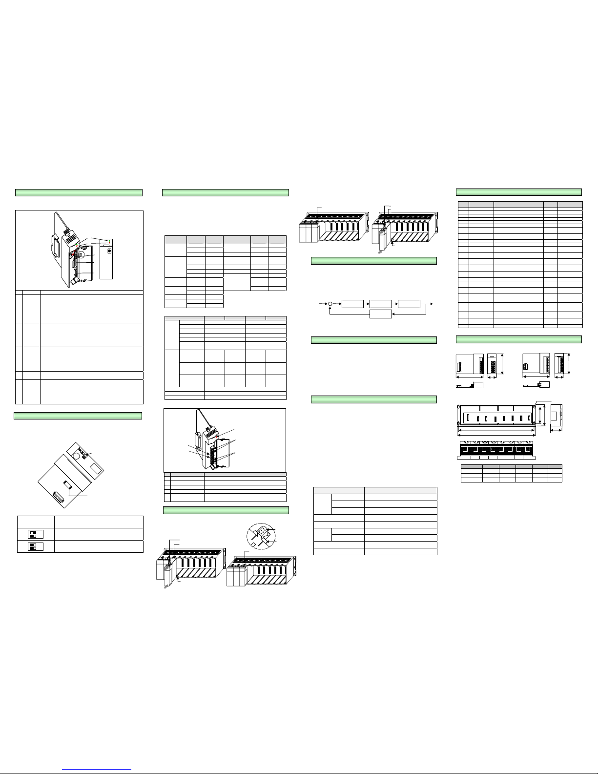
The following describes the names and functions of parts of the CPU module.
No. Name Function
1 RUN LED
Indicates the operation status of the CPU module.
•
On : when the CPU module operates with the mode setting switch in the
local or remote RUN state.
•
Off : when the followings occur
The voltage is not normally supplied to the CPU module.
The mode setting switch is in the STOP or PAU/REM state.
An error which makes operation stop is detected.
2 STOP LED
•
On : when the mode setting switch is in the local or remote STOP state.
•
Off : when the followings occur
The mode setting switch is in the local RUN or local PAUSE state.
The operation state is in the RUM/PAUSE/DEBUG state.
•
Flickering : when an error is detected by self-diagnosis during
operation.
3
Mode
setting
switch
Sets the operation mode of the CPU module. .
•
RUN : Program operation is executed.
•
STOP : Program operation is temporarily stopped.
•
PAU/REM :
PAUSE : Program operation is temporarily stopped.
REMOTE: Used for the remote operation
4
RS-232C
connector
9-pin connector for KGL-WIN and Cnet (RS-232C)
5
RS-422
and HSC
terminal
(B/C type
only)
Pin No RS-422/485 High Speed Counter
1 RDA A phase input
2 RDB B phase input
3 SDA A/B phase common
4 SDB Preset input (+24V)
5 S.G Preset common (0V)
This chapter describes how to store and operate user program with the flash memory .
Flash memory is used to store a user program and installed in PLC.
1) Structure
Read / Write is available to flash memory in accordance with selection of DIP switch.
Selection of DIP switch
for flash memory
Operation
PLC is operated by the program in flash memory when power
on or PLC reset.
PLC recognize that no program is in flash memory.
( Caution : Lower switch should be at the off position. )
User program can be written to flash memory at the PLC stop mode and then the selection of
switch is ignored.
This chapter describes type and specifi cations of the power supply modules
1) Selection of power supply module
Selection of the power supply module is determined by the total current consumption
of digital input modules, special modules and communications modules, etc. whose
powers are supplied by the power supply module.
If total load overrun the rated output capacity, the system will not normally operate.
When configuring a system, select a power supply module with due consideration of
current consumption of each module.
Current Consumption of K200S Series Modules (Unit:㎃)
Module
Model
Name
Current
Consumption
Module
Model
Name
Current
Consumption
K3P-07AS 170 K3Y-303S 140
K3P-07BS 210
Transistor Output
K3Y-304S 145
CPU
K3P-07CS 170 A/D Module K3F-AD2A 50
K3X-110S 40 K3F-DV2A 50
K3X-210S 70
D/A Module
K3F-DI2A 50
K3X-240S 70 High Speed Counter K3F-HSCA 220
K3X-310S 75 Positioning module K 3F-POPA 345
DC 12/24V
Input
K3X-340S 75 K3F-CU2A 140
AC110V Input K3X-120S 35
Computer link module
(Cnet)
K3F-CU4A 180
AC220V Input K3X-130S 35 K3F-FUEA 215
K3Y-101S 210
Fnet I/F module
K3F-RBEA 215
Relay Output
K3Y-201S 400
Triac Output K3Y-102S 190
K3Y-203S 180
Transistor
Output
K3Y-204S 170
2) Specification
Item K3S-302S K3S-304S K3S-012S K3S-014S
Voltage
AC100 ~ 240V (85∼264V)
DC12 ~ 24V
Frequency
50/60Hz(47∼63 Hz)
-
Current 0.7/0.35A 0.7 / 1.8A
Inrush Current 30A or less 40A or less
Efficiency 65% or more (Normal load) 60% or more (normal load)
Fuse Type 250VAC / 2A 250VAC/ 3A
Input
Dropout Tolerance 20ms or less 1ms or l ess
Voltage
DC5V
DC24V
DC5V
DC+15V
DC-15V
DC5V
DC5V
DC+15V
DC-15V
Current
DC5V:2A
DC24V:0.3A
DC5V:2A
DC+15V:0.5A
DC-15V:0.2A
DC5V : 2A
DC5V:2A
DC+15V:0.5A
DC-15V:0.2A
Output
Over-current
Protection
DC5V:2.2A
DC24V:0.33A
DC5V:2.2A
DC+15V:0.55A
DC-15V:0.22A
DC5V : 2.2A
DC5V:2.2A
DC+15V:0.55A
DC-15V:0.22A
LED Indication On : The output voltage is normal
Allowable Cable Specification
0.75∼2mm²
Weight (kg) 0.32
3) Names of Parts
No. Name Description
1 Power LED
*
The LED indicator for DC5V power
2 Power Input Terminal
*
The terminal to connect 100~240VAC power
3 LG Terminal
*
Line ground
4 FG Terminal
*
Frame ground
5
DC24V Terminal
DC24VGTerminal
*
Supply DC24V power to the other modules (K3S-302S)
*
No Connection(K3S-304S, K3S-012S, K3S-014S)
The following explains that how to mount/dismount various module to the base.
1) Mounting a module
- Insert the module to mounting slot along sliding guide.
- Check that the module is firmly mounted onto the base.
2) Dismounting a module
- First, push the locked hook (①) and pull the module with direction of arrow (②).
K3P-07BS and K3P-07CS module include PID (Proportional Integral Differential) function,
and no external PID module is required.
1) Characteristics of K200S PID function
a) PID function is included in the CPU module, and no PID module is required.
b) User can select forward or reverse operation.
c) P, PI, PID or On/Off operation modes are available.
d) Manual output (user-defined output) is available.
e) Sampling time can be varied for flexibility of control system.
2) Programming of PID control function
- Refer the MASTER-K Programming manual for details
1) Introduction
The K3P-07BS module has RS-422/485 master function and can operate as master
station of 1:N network.
2) Functions
a) User can define a data access block and set time-out value at each blocks. The
maximum size of block is 64 words.
b) Maximum station number is 32 stations.
c) According to the parameter setting, the operation mode and error code of slave
stations is stored at the relevant flag.
d) The communication status can be monitored with the monitoring function of KGL-
WIN software.
1) Introduction
The K3P-07CS module includes a built-in high speed counter, and it can count a
fast pulse input that are generated by encoder or pulse generator.
The built-in HSC has following functions;
-
3 counter functions as followings
-
1-phase up / down counter : Up / down is selected by user program
-
1-phase up / down counter : Up / down is selected by external B phase input
-
2-phase up / down counter : Up / down is automatically selected by the
phase difference between phase A and B.
-
Multiplication (1, 2, or 4) with 2-phase counter
-
2-phase pulse input multiplied by one : Counts the pulse at the leading edge
of phase A.
-
2-phase pul se i nput multipli ed by two : Counts the pulse at the leading /
falling edge of phase A.
-
2-phase pul se i nput multipli ed by four : Counts the pulse at the leading /
falling edge of phase A and B
2) Performance specifications
Items Specifications
Types Phase A, Phase B, Preset
Rated level 24VDC (13mA)
Input
signal
Signal type Voltage input
Counting range 0 ~ 16,777,215 (Binary 24 bits)
Max. counting speed 50k pps
1-phase Sequence program or B-phase input
Up /
Down
selection
2-phase Auto-select by phase difference of phase A and B
Multiplication 1, 2, or 4
Preset input Sequence program or external preset input
1) Error code
Error
code
Message Description Error Cause
Operation
status
Corrective Action
h0001 System error Internal H/W fault STOP Contact A/S center
h0002 OS ROM error Internal H/W O/S ROM fault STOP Contact A/S center
h0003 OS RAM error Fault of RAM for internal system STOP Contact A/S center
h0004 Data RAM error Fault of RAM for internal data STO P Contact A/S center
h0005 Program RAM error Fault of RAM for internal program STOP Contact A/S center
h0006 G/ A error Internal Gate Array(G/A) fault STOP Contact A/S center
h0007
Expansion base power
fault
It is down or fault to power for the expansion base STOP
Check the power of
expansion base center
h0008 CP U WDT error
It is over to the monitoring time for operation delay
of CPU
STOP Contact A/S center
h0009 Special RAM error Internal special RAM fault RUN/STOP Contact A/S center
h000A Fuse error It is opened to fuse to be used for the I/O module STOP Contact A/S center
h000B Instruct ion code error
It is to be used instruction code which is impossible
to decode
STOP Contact A/S center
h000C Flash memory error It is fault to flash memory to be used STOP
Confirm flash memory
or replace
h000D I/O error
Module dismounting or additional mounting during
run, bad contact, I/O fault, expansion cable fault
STOP
Confirm I/O module or
expansion cable
h0011 Maximum I/O slot error
It is over maximum I/O points to the I/O module
mounted(Fnet, Cnet)
STOP Replace I/O modul e
h0012
Special function module
error
Special function module interface part fault STOP Contact A/S center
h0020 Parameter error Specified parameter fault S TOP Resetting parameters
h0021 Specif ied I/O error
It is different to I/O parameters specified and I/O
module mounted
STOP
Correct the parameters
or replace the I/ O module
h0022 Maximum I/O slot error
It is over maximum I/O points to the I/O module
mounted
STOP Replace the I/O mod ule
h0030 Operation error
Use of the improp er operand when i t is used B CD
conversion instruction (except for 0~9 )
In case of over in the domain of #D
RUN/STOP Correct the program
h0031 W DT error The scan time is over monitoring time STOP
Increment the scan time
in parameters or add
WDT instruction
h0040 Code check error
It is used to the instruction which is impossible to
decode
STOP Correct the program
h0049 Syntax error
Improper program input condition or error of LOAD
Instruct ion overused
STOP Correct the program
h0050 Battery error Dismounted battery or abnormal voltage RUN Replace the battery
◆
Power Supply Module
◆
CPU & I/O Module
◆
Base
Slot Type A B C D E
4 slots 230.5 244 92 110 62
6 slots 300.5 314 92 110 62
8 slots 370.5 384 92 110 62
6. Usi
ng The User Program in Flash Memory
7. P
ower Supply Modules
8. M
ounting and Dismounting of Module
9. PID
control function
(K3P-07BS / K3P-07CS)
13. Di
mension (mm)
Dip switch for operation
Flash me mory
①
②
⑤
③
④
PID operation D/A conversion Actuator
A/D conversion
SV DV PV
10. RS-422/485
master function
(K3P-07BS)
①
②
③
④
⑤
11. Built-in high
speed counter
(K3P-07CS)
12. T
roubleshooting
Sliding Guide
Locking Hook
Locking part for hook
Locking part
for hook
Locking Hook
4 – ψψψψ 4.5
4.54.5
4.5
100
100100
100
45
4545
45
110
110110
110
100
100100
100
35
3535
35
110
110110
110
Locking part for hook
Sliding Guide
Locking part for hook
Locking Hook
5. Parts N
ames and Descriptions
 Loading...