


0
Service Manual
(K1)
LG Electronics

1
Ch 1. Service information
Ch 2. Locations
Ch 3. System information
· Specification
· System Block Diagram
· Fn key combinations
· Status indicators
· BIOS Flash
· BIOS Setup
Ch 4. Symptom-to-part index
· Power system checkout
· Numeric error codes
· Error messages
· LCD-related symptoms
· Indeterminate problems
Ch 5. Removing and replacing a part (FRU)
Ch 6. Part list
· Part list
· Exploded view
Contents
2
Chapter 1. Service information
1-1. Important service information
Strategy for replacing parts (FRU-Field Replaceable Units)
Before replacing parts
Make sure that latest BIOS and drivers are installed before replacing any parts (FRUs) listed in this
Caution
The BIOS configuration on the computer you are servicing may have been customized.
Running Automatic Configuration my alter the settings. Note the current configuration settings;
then, when service has been completed, verify that those settings remain in effect.
Strategy for replacing a hard-disk drive
You have to get a User’s approval before formatting or replacing a hard-disk drive. You must let the User
know that the user is responsible for the loss data
Caution
The drive startup sequence in the computer you are servicing may have been changed. Be
extremely careful during write operations such as copying, saving, or formatting. If you select an
incorrect drive, data or programs can be overwritten.
Use the following strategy to prevent unnecessary expense for replacing and servicing parts
1. If you are instructed to replacing a part but the replacement does not correct the problem, reinstall the
original part before you continue.
2. Some computers have both a processor board and system board. If you are instructed to replace either
the processor board or the system board, and replacing one of them does not correct the problem,
reinstall that board, and then replace the other one.
3. If an adapter or device consists of more than one part, any of the parts (FRUs) may be the cause of the
error. Before replacing the adapter or device, remove the parts (FRUs), one by one, to see if the
symptoms change. Replace only the part that changed the symptoms.
Ch1. Service information
3
1-2. Safety notices
Warning
Before the computer is powered-on after part (FRU) replacement, make sure all screws, springs,
and other small parts are in place and are not left loose inside the computer. Verify this by
shaking the computer and listening for rattling sounds. Metallic parts or metal flakes can cause
electrical shorts.
Warning
some standby batteries contain a small amount of nickel and cadmium. Do not disassemble
a standby battery, recharge it, throw it into fire or water, or short-circuit it. Dispose of the battery
as required by local ordinances or regulations. Use only the battery in the appropriate parts
listing. Use of an incorrect battery can result in ignition or explosion of the battery
Warning
The battery pack contains small amounts of nickel. Do not disassemble it, throw it into fire or
water, or short-circuit it. Dispose of the battery pack as required by local ordinances or
regulations. Use only the battery in the appropriate parts listing when replacing the battery pack.
Use of an incorrect battery can result in ignition or explosion of the battery.
Warning
If the LCD breaks and the fluid from inside the LCD gets into your eyes or on your hands,
immediately was the affected areas with water for at least 15 minutes. Seek medical care if any
symptoms from the fluid are present after washing.
Warning
To avoid shock, do not remove the plastic cover that protects the lower part of the inverter card.
Warning
Though the main batteries have low voltage, a shorted or grounded battery can produce enough
current to burn personnel or combustible materials.
Warning
Before removing any part (FRU), turn off the computer, unplug all power cords from electrical
outlets, remove the battery pack, and then disconnect any interconnecting cables.
Ch1. Service information
4
1-3. Safety information
General safety
Follow these rules to ensure general safety
· Observe good housekeeping in the area of the machines during and after maintenance.
· When lifting any heavy object
1. Ensure you can stand safely without slipping.
2. Distribute the weight of the object equally between your feet.
3. Use a slow lifting force. Never move suddenly or twist when you attempt to lift.
4. Lift by standing or by pushing up with your leg muscles
(This action removes the strain from the muscles in your back.)
· Do not attempt to lift any object weights more then 16kg(35lb) or object that you think are too heavy for you.
· Do not perform any action that causes hazards to the customer, or that makes the equipment unsafe.
· Before you start the machine, ensure that other service representatives and the customer’s personnel are
not in a hazardous position.
· Place removed covers and other parts in a safe place, away from all personnel, while you are servicing the
machine.
· Keep your tool box away from walk areas so that other people will not trip over it.
· Do not wear loose clothing that can be trapped in the moving parts of a machine. Make sure that your
sleeves are fastened or rolled up above your elbows. If your hair is long, fasten it.
· Insert the ends of your necktie or scarf inside clothing or fasten it with a nonconductive clip, approximately
8 centimeters(3 inches) from the end.
· Do not wear jewelry, chains, metal-frame eyeglasses, or metal fasteners for you clothing.
· Wear safety glasses when you are hammering, drilling, soldering, cutting wire, attaching springs, using
solvents, or working in any other conditions that might be hazardous to your eyes.
· After service, reinstall all safety shields, guards, labels, and ground wires. Replace any safety device that
is worn or defective.
· Reinstall all covers correctly before returning the machine to the customer.
Caution
Metal objects are good electrical conductors.
Ch1. Service information
5
Electrical safety
Observe the following rules when working on electrical equipment.
Important
Use only approved tools and test equipment. Some hand tools have handles covered with a soft
material that does not insulate you when working with live electrical currents.
Many customers have, near their equipment, rubber floor mats that contain small conductive
fibers to decrease electrostatic discharges. Do not use this type of mat to protect yourself from
electrical shock.
· Find the room emergency power-off switch, disconnecting switch, or electrical outlet. If an electrical outlet.
If an electrical accident occurs, you can then operate the switch or unplug the power cord quickly.
· Do not work alone under hazardous conditions or near equipment that has hazardous voltages.
· Disconnect all power before
1. Performing a mechanical inspection
2. Working near power supplies
3. Removing or installing main units
· Before you start to work on the machine, unplug the power cord. If you cannot unplug it, ask the customer
to power-off the wall box that supplies power to the machine and to lock the wall box in the off position.
· If you need to work on a machine that has exposed electrical circuits, observe the following precautions :
Ensure that another person, familiar with the power-off controls, is near you.
Caution
Another person must be there to switch off the power, if necessary.
· Use only one hand when working with powered-on electrical equipment. Keep the other hand in your
pocket or behind your back
Caution
An electrical shock can occur only when there is a complete circuit. By observing the above rule,
you may prevent a current from through your body.
· When using testers, set the controls correctly and use the approved probe leads and accessories for that
tester
Ch1. Service information

6
· Stand on suitable rubber mats (obtained locally, if necessary) to insulate you from grounds such as metal
floor strips and machine frames.
· Observe the special safety precautions when you work with very high voltages. These instructions are in
the safety sections of maintenance information. Use extreme care when measuring high voltages.
· Regularly inspect and maintain your electrical hand tools for safe operational condition.
· Do not use worn or broken tools and testers.
· Never assume that power has been disconnected from a circuit. First check that it has been powered off.
· Always look carefully for possible hazards in your work area. Examples of these hazards are moist floors,
non-grounded power extension cables, power surges, and missing safety grounds.
· Do not touch live electrical circuits with the reflective surface of a plastic dental mirror. The surface is
conductive such touching can cause personal injury and machine damage.
· Do not service the following parts with the power on when they are removed from their normal operating
places in a machine.
1. Power supply units
2. Pumps
3. Blowers and fans
4. Motorgenerators
and similar units. (This practice ensure correct grounding of the units.)
· If an electrical accident occurs
1. Use caution ; do not become a victim of yourself.
2. Switch off power.
3. Send another person to get medical aid.
Ch1. Service information

7
Safety inspection guide
The purpose of this inspection guide is to assist you in identifying potentially unsafe conditions.
As each machine was designed and built, required safety items were installed to protect users and service
personnel from injury. This guide addresses only those items. You should use good judgment to identify
potential safety hazards due to attachment of non-LG features or options not covered by this inspection
guide.
If any unsafe conditions are present, you must determine how serious the apparent hazard could be and
whether you can continue without first correcting the problem.
· Consider these conditions and the safety hazards they present
1. Electrical hazards, especially primary power (primary voltage on the frame can cause serious or fatal
electrical shock)
2. Mechanical hazards, such as loose or missing hardware
Refer to the following checklist and begin the checks with the power off, and the power cord disconnected.
· Checklist
1. Check exterior covers for damage (loose, broken, or sharp edges)
2. Power off the computer. Disconnect the power cord.
3. Check the power cord for :
a. A third-wire ground connector in good condition. Use a meter to measure third-wire ground continuity
for 0.1 or less between the external ground pin and frame ground.
b. The power cord should be the type specified in the parts list.
c. Insulation must not be frayed or worn.
4. Remove the cover.
5. Check for any obvious non-LG alterations. Use good judgment as to the safety of any non-LG
alterations.
6. Check inside the unit for any obvious unsafe conditions, such as metal filings, contamination, water or
other liquids, or signs of fire or smoke damage.
7. Check for worn, frayed, or pinched cables.
8. Check that the power-supply cover fasteners (screw or rivets) have not been removed or tampered with.
Ch1. Service information

8
Handling devices that are sensitive to electrostatic discharge
Any computer part containing transistors or integrated circuits (ICs) should be considered sensitive to
electrostatic discharge (ESD). ESD damage can occur when there is a difference in charge between
objects. Protect against ESD damage by equalizing the charge so that the machine, the part, the work mat,
and the person handling the part are all at the same charge.
Note
Use product-specific ESD procedures when they exceed the requirements noted here.
Make sure that the ESD protective devices you use have been certified (ISO9000) as fully effective.
· When handling ESD-sensitive parts :
1. Keep the parts in protective packages until they are inserted into the product.
2. Wear a grounded wrist strap against your skin to eliminate static on your body.
3. Prevent the part from touching your clothing. Most clothing retains a charge even when you are wearing
a wrist strap.
4. Use the black side of a grounded work mat to provide a static-free work surface. The mat is especially
useful when handling ESD-sensitive devices.
5. Select a grounding system, such as those listed below, to provide protection that meets the specific
service requirement.
Note
The use of a grounding system is desirable but not required to protect against ESD damage.
a. Attach the ESD ground clip too any frame ground, ground braid, or green-wire ground.
b. Use an ESD ground or reference point when working on a double-insulated or battery-operated
system. You can use coax or connector-outside shells on these systems.
c. Use the round ground-prong of the AC plug on AC-operated computers.
Ch1. Service information
Grounding requirements
Electrical grounding of the computers is required for operator safety and correct system function.
Proper grounding of the electrical outlet can be verified by a certified electrician.

9
When a CD-ROM drive, DVD drive or the other laser product is installed, note the following :
Caution
Use of controls or adjustments or performance of procedures other than those specified here in
might result in hazardous radiation exposure.
1-4. Laser compliance statement
Opening the CD-ROM drive, DVD-ROM drive or the other optical storage device could result in exposure
to hazardous laser radiation.
There are no serviceable parts inside those drives. Do not open
Danger
Emits visible and invisible laser radiation when open. Do not stare into the beam , do not view
directly with optical instruments, and avoid direct exposure to the bean.
1-5. Backup (Standby) RTC battery safety information
When replacing or disposing of the backup (standby) RTC battery, note the following :
Ch1. Service information

10
1-6. Read this first
Before you go to the checkout guide, be sure to read this section.
Important Notes
· Only trained personnel certified by LG should service the computer.
· Read the entire FRU removal and replacement page before replacing any FRU.
· Use new nylon-coated screws when you replace FRUs.
· Be extremely careful during such write operations as copying, saving, formatting.
Drives in the computer that you are servicing sequence might have been altered. If you selected an
incorrect drive, data or programs might be overwritten.
· Replace FRUs only for the correct mode.
· When you replace a FRU, make sure the model of the machine and the FRU part number are correct by
referring to the FRU parts list.
· A FRU should not be replaced because of a single, irreproducible failure. Single failures can occur for a
variety of reasons that have nothing to do with a hard ware defect, such as cosmic radiation,
electrostatic discharge, or software errors.
· Consider replacing a FRU only when a problem recurs. If you suspect that a FRU is defective, clear the
error log and run the test again. If the error does not recur, do not replace the FRU.
· Be careful not to replace a non-defective FRU.
What to do first
You must fill out the record form first.
During the warranty period, the customer may be responsible for repair costs if the computer damage was
caused by misuse, accident, modification, unsuitable physical or operating environment, or improper
maintenance by the customer. The following list provides some common items that are not covered under
warranty and some symptoms that might indicate that the system was subjected to stress beyond normal
use. Before checking problems with computer, determine whether the damage is covered under the
warranty by referring to the following :
Ch1. Service information

11
The followings are not covered under warranty :
· CD panel cracked from the application of excessive force or from being dropped
· Scratched (cosmetic) parts
· Distortion, deformation, or discoloration of the cosmetic parts
· Cracked or broken plastic parts, broken latches, broken pins, or broken connectors caused by excessive
force
· Damage caused by liquid spilled into system
· Damage caused by improper insertion of a PC Card or the installation of an incompatible card
· Damage caused foreign material in the diskette drive
· Diskette drive damage caused by pressure on the diskette drive cover or by the insertion of a diskette
with multiple labels
· Damaged or bent diskette eject button
· Fusses blown by attachment of a non-supported device
· Forgotten computer password (making the computer unusable)
· Sticky keys caused by spilling a liquid onto the keyboard
The following symptoms might indicate damage caused by non-warranted activities :
· Missing parts might be a symptom of unauthorized service or modification.
· If the spindle of a hard-disk drive becomes noisy, it may have been subjected to excessive force, or
dropped.
Ch1. Service information
12
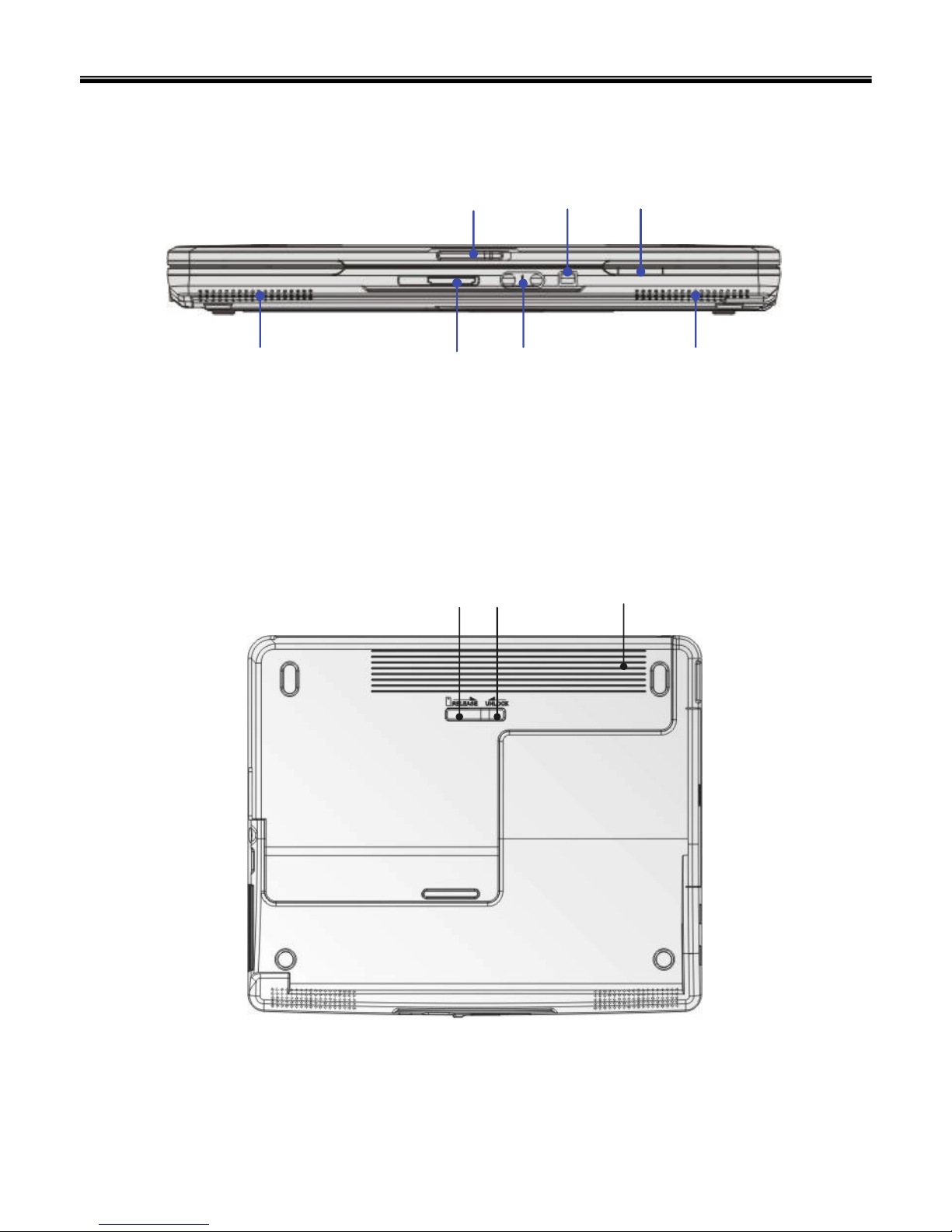
Front view
Chapter 2. Locations
Ch2. Locations
1. Cover Latch
2. IEEE 1394
3. Status LED
4. 3 in 1 Card Reader
5. Audio Port Connectors
6. Stereo Speakers
X
\
Z
[
Y
]]
Bottom view
XY Z
1. Battery Release Button
2. Battery Lock/Unlock Button
3. Battery Pack
13
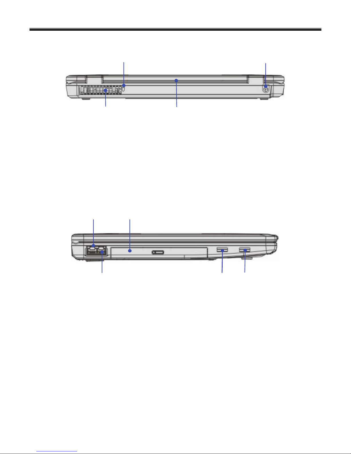
1. RJ-11 Connector
2. RJ-45 Connector
3. Optical Storage Device
4. USB Port
Rear view
Ch2. Locations
1. Kensington Lock
2. Ventilator
3. Power Connector
4. Battery Pack
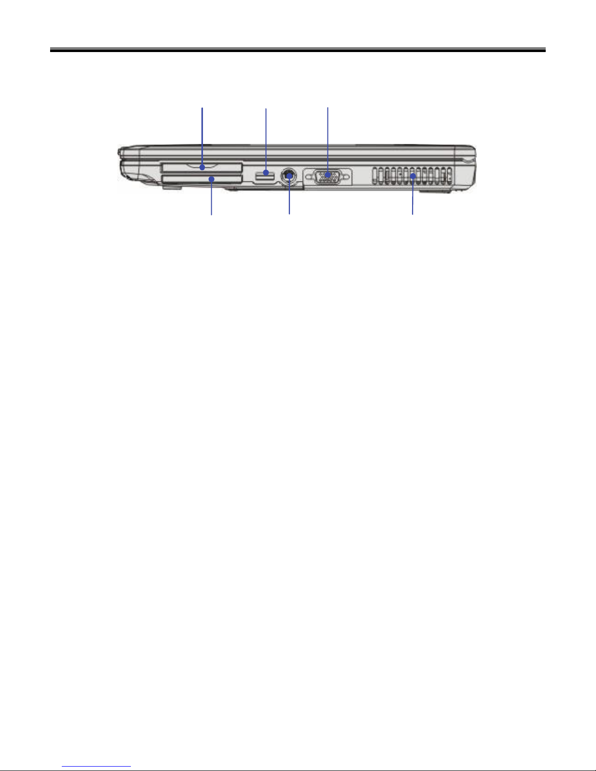
Left view
Y
X
Z
[
X
Y
Z
[
[
14
Ch2. Locations
Right view
1. Express Card Slot
2. PC Card Slot
3. USB Port
4. S-Video Connector
5. VGA Port
6. Ventilator
X
Y
Z
[
\
]

15
-CPU
· Dothan 1.60GHz~1.86GHz
· Celeron 1.20GHz~1.50GHz
·μFCPGA
- Main Chipset & Graphic
· Intel 915GM, ICH6-M
-Memory
·2 SODIMM
· DDR2 PC2-4300 Capable(533MHz)
-LCD
· 15” XGA
-HDD
· 2.5" 9.5mm 40/60GB PATA Type
- Communication
·MDC AC’97
· Realtek 8100C
- Wireless LAN Solution
· 802.11 bg
- Card Slot
· Express Card Slot
· Cardbus Card Slot(PCMCIA)
· 3-in-1 Card Slot
- ODD
· Fixed Optical Storage
· DVD-Combo/DVD Super multi
-Port
· VGA, 3X USB(2.0), RJ11, RJ45, Headphone-out, Mic-in, AC-in, IEEE1394, S-Video
- Input Devices
· Keyboard:86Key Keyboard
· Touchpad
- Buttons
· Power, Volume Down, Volume Up
- Indicator (LED)
· Power On, Charge, HDD, Caps Lock, Num Lock, Wireless
Specification
Chapter 3. System information
Ch3. System information

16
- Indicator (LED)
· AC-in, Power On, Charge, HDD, Caps Lock, Num Lock, Wireless
-Power
· 90 Watt 19V 4.74A Adapter
-Audio
· Realtek ALC655, Sound Blaster compatible
- Battery
· 6 Cell 5.2AHr, CYLINDRICAL(Li-Ion)
Ch3. System information
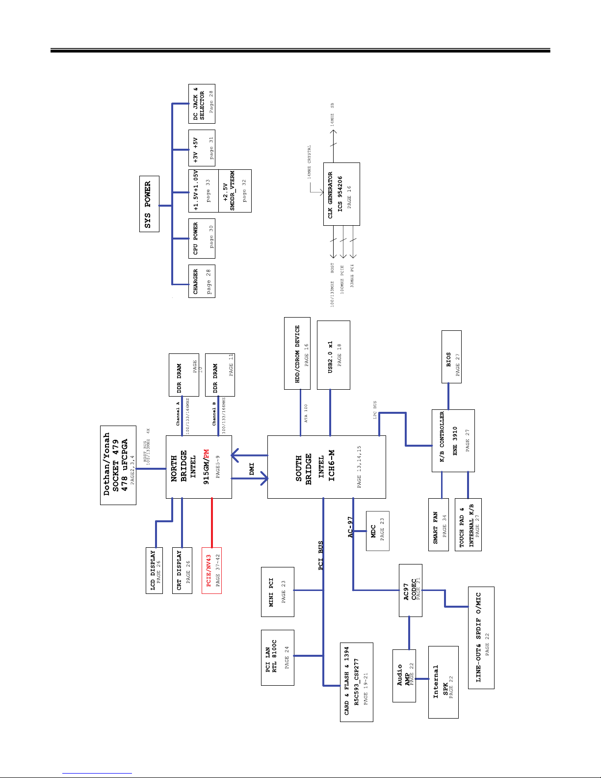
17
■System Block Diagram
Ch3. System information

18
Fn key combinations
The following table shows the function of each combination of Fn with a function key.
Function of Fn keys has nothing to do with Operating System.
Ch3. System information
Force the computer to enter power-saving mode. (ex: system standby or hibernation) [Fn]+[F12]
Mute(Sound On / Off) [Fn]+[F9]
Sound up [Fn]+[F8]
Sound down [Fn]+[F7]
Brighten the LCD [Fn]+[F5]
Darken the LCD [Fn]+[F4]
Press the [Fn]+[F3] combination each time for Touchpad Enable / Touchpad Disable . [Fn]+[F3]
Monitor toggle. When the computer is attached to an external monitor, you can change the display
output location with [Fn] + [F7] combination.
[Fn]+[F2]
19
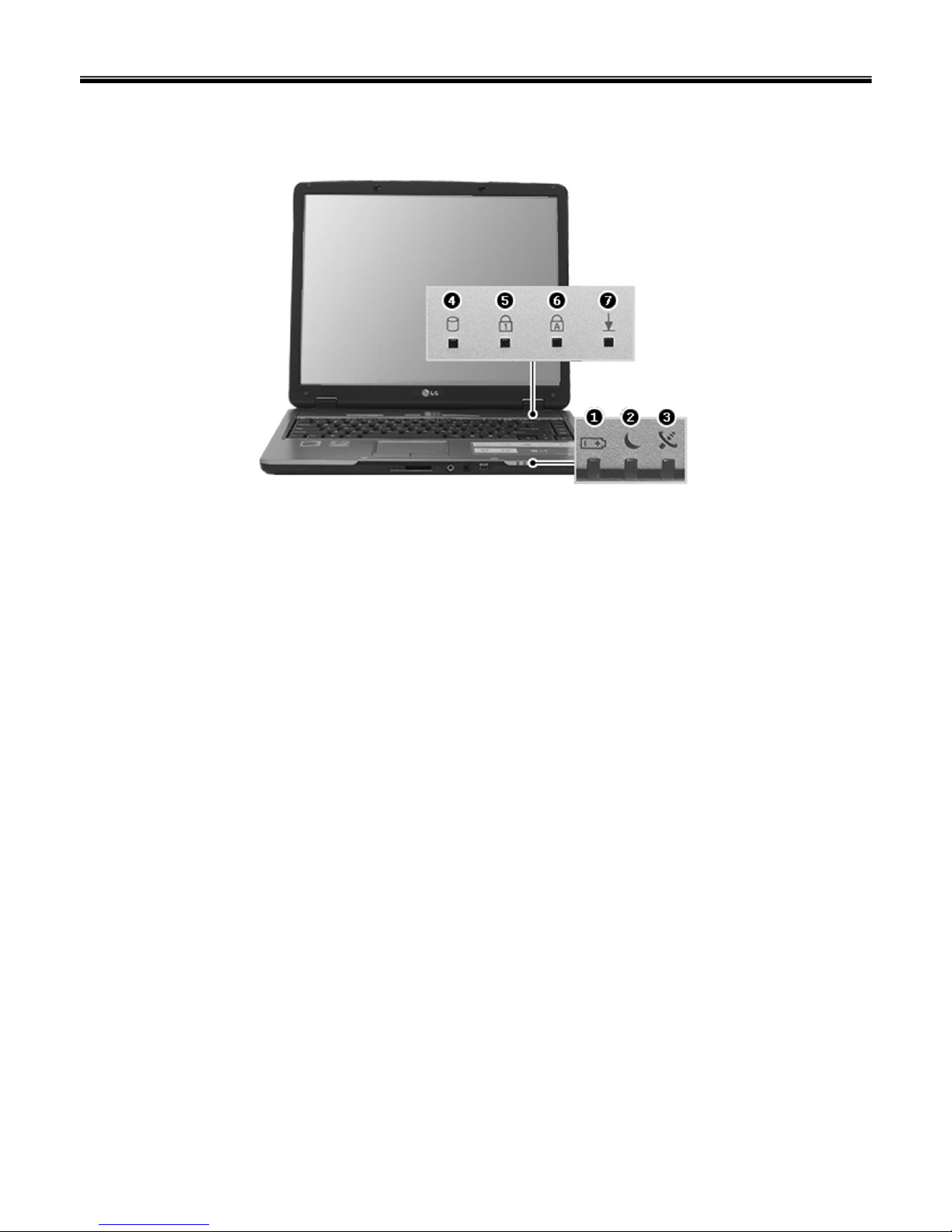
Status indicators
Ch3. System information
The system status indicators show the status of the computer
1. Battery Indicator
- Charging the battery: Green
- When the battery is fully charged or the computer is not connected to an AC Adapter: OFF
- When the battery power is under 10% of its maximum capacity: Orange
- The battery is defective: Orange blinking
2. Power On/Off/Suspend Indicator
- Stand by mode: Red blinking
- When the System is operating: OFF
3. Wireless LAN Indicator
- Wireless LAN is in use: ON
- Wireless LAN is not in use: OFF
4. Hard disk drive indicator
- Indicator lights up when the Notebook PC access to the hard disk drive.
※ Do not turn off the computer when the drive indicator lights up. It may cause data loss to the computer.
5. Num Lock Indicator
- You can press the combination of [Fn] and [Ins(Num Lk)] keys to enable the embedded numeric keypad.
Press the combination of [Fn] and [Ins(Num Lk)] keys again to disable the embedded numeric keypad.
6. Caps Lock Indicator
- Caps Lock indicator lights up when Caps Lock key is pressed. When this indicator lights up, you can
type capital letters without pressing the Shift key.
7. Scroll Lock Indicator
- ScrollLock indicator lights up when the combination of the Fn and Num lock key is pressed.

20
BIOS Flash
You can update BIOS using a floppy disk drive.
Because this system is not equipped with any floppy disk drive, you have to use an external USB drive for
a BIOS update. In order to boot up with an USB drive, please set Removable Device as the first boot up
drive in the boot menu of BIOS setup.
· How to update flash ROM in DOS
1. Create ‘boot up’ flash update diskette.
2. Copy a ROM image file (*.wph) into the root of the flash update diskette.
3. Copy phlash16.exe to the flash update diskette.
4. Insert the diskette into the FDD of your computer.
5. Boot your computer with the diskette, and type ‘phlash16*.wph /mode=n’.
6. Cold boot and follow the instruction displayed on the screen.
· Flash options /mode=n
0 – Default mode. Keep the current DMI information and update BIOS image only.
1 – Update DMI information only.
If new DMI information is not specified, the current DMI information is left unchanged.
2 – Update BIOS and DMI information.
If new DMI information is not specified, the current DMI information is left unchanged.
3 – Update BIOS and DMI information.
DMI information is updated to the DMI string and options specified in the new BIOS image.
Note
DMI is Desktop Management Interface
Ch3. System information

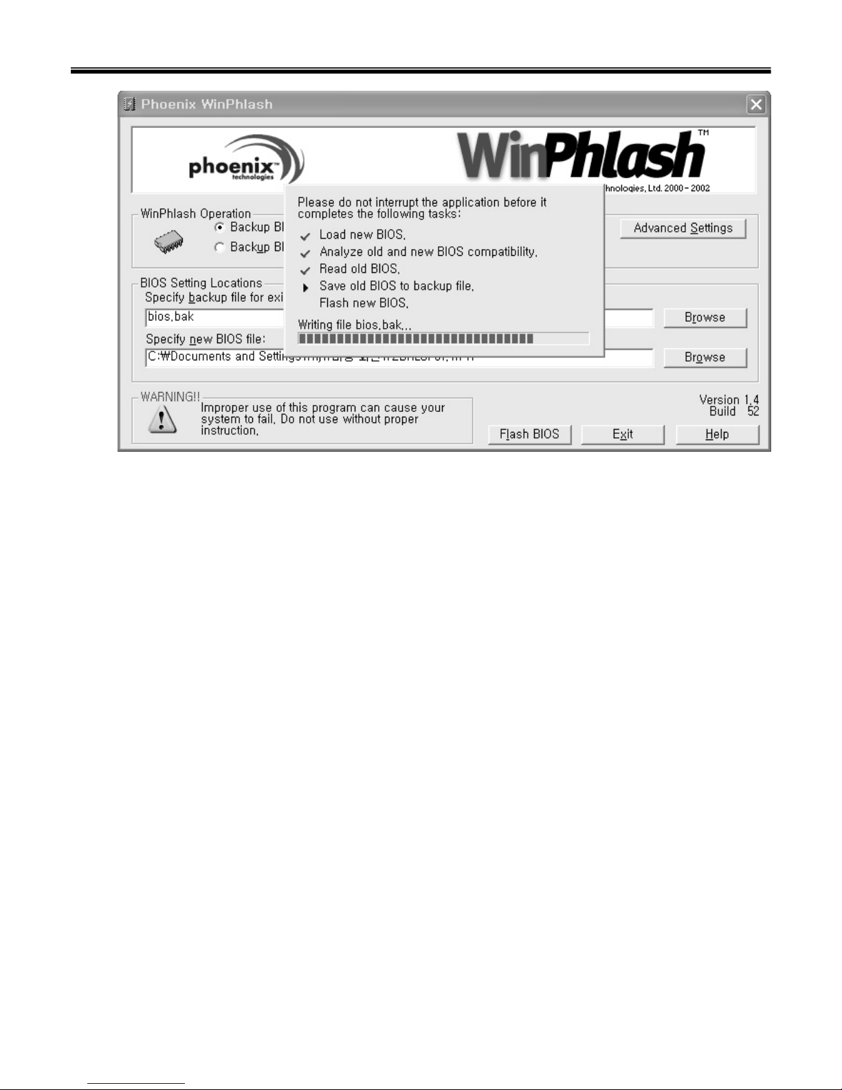
21
1. Quit all running programs.
2. Start WINPHLASH.EXE.
3. Select the procedure you want :
a. Backup BIOS and Flash BIOS with new settings
b. Backup BIOS Only
4. Specify the locations for backup and new BIOS files in BIOS Setting Locations.
a. Enter the name of the backup file for existing BIOS or click Browse to locate the file.
b. Enter the name of the new BIOS file or click Browse to locate the file.
5. Click Advanced Settings button to access the advanced settings
6. Click Flash BIOS button to start flash BIOS.
7. Wait for the operation to complete. WinPhlash may take one or two minutes to complete flash BIOS
operation.
How to update flash ROM in Windows
Ch3. System information
22
8. After the completion, ‘System BIOS was successfully updated’ appears on the screen, then the
computer restarts.
9. After the restart, make sure the system BIOS is updated.
10. If your computer does not restart automatically, turn off your computer and then turn it back on by
pressing power button.
Ch3. System information
23
Ch3. System information
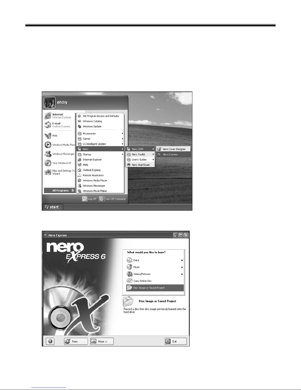
BIOS Release Process and Making Bootable CD
1. LGE(Korea) will send BIOS Image (*.iso) to each Service Centers when we have a new revision.
(Please refer to the BIOS Table (Document No. SBE-HA-01) for latest BIOS)
2. Service center will make Bootable Image CD with Image file(*.iso) as below
a. Insert empty disc to CD-RW Drive and start Nero Burning ROM.
b. Select Disc Image or Saved Project.
24
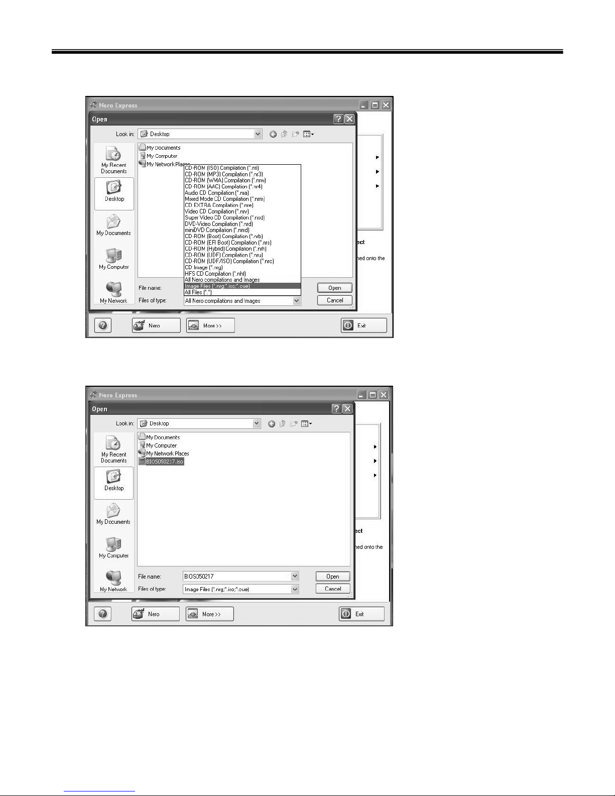
Ch3. System information
c. Select File Format as "Image Files(*.iso)".
d. Open Image File(*.iso) which is sent from LGE
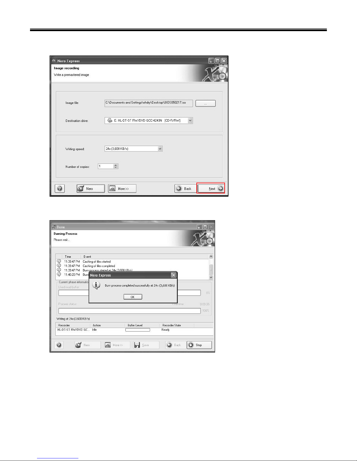
25
Ch3. System information
e. Tab Next then burning will be started
f. Burn process completed as below, and tab “OK”

26
Ch3. System information
BIOS/EC Flash Process
1. Insert Bootable CD in PC, and Turn it on, then PC will boot by DOS mode as below
(If the EC is not correct or old version, then automatically update EC first and reboot again)
2. Type in Mode Name at the “WIP ID :” then press Enter key (You must use Capital Letter)
(You can see the Model Name in ID Label at the bottom Case of PC: “M/N: LMXX-XXXX”)
3. Type in Serial No at the “WIP ID :” then press Enter key (You must use Capital Letter)
(You can see the Serial No in ID Label at the bottom Case of PC: “S/N: 412KIXXXXXXXX”(13digits))
27
Ch3. System information
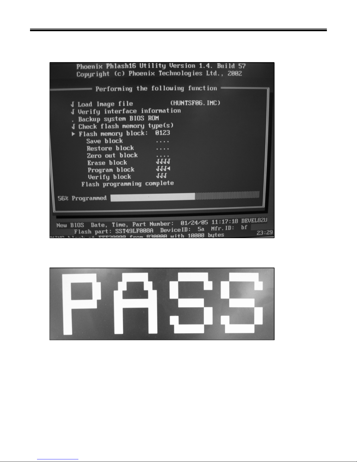
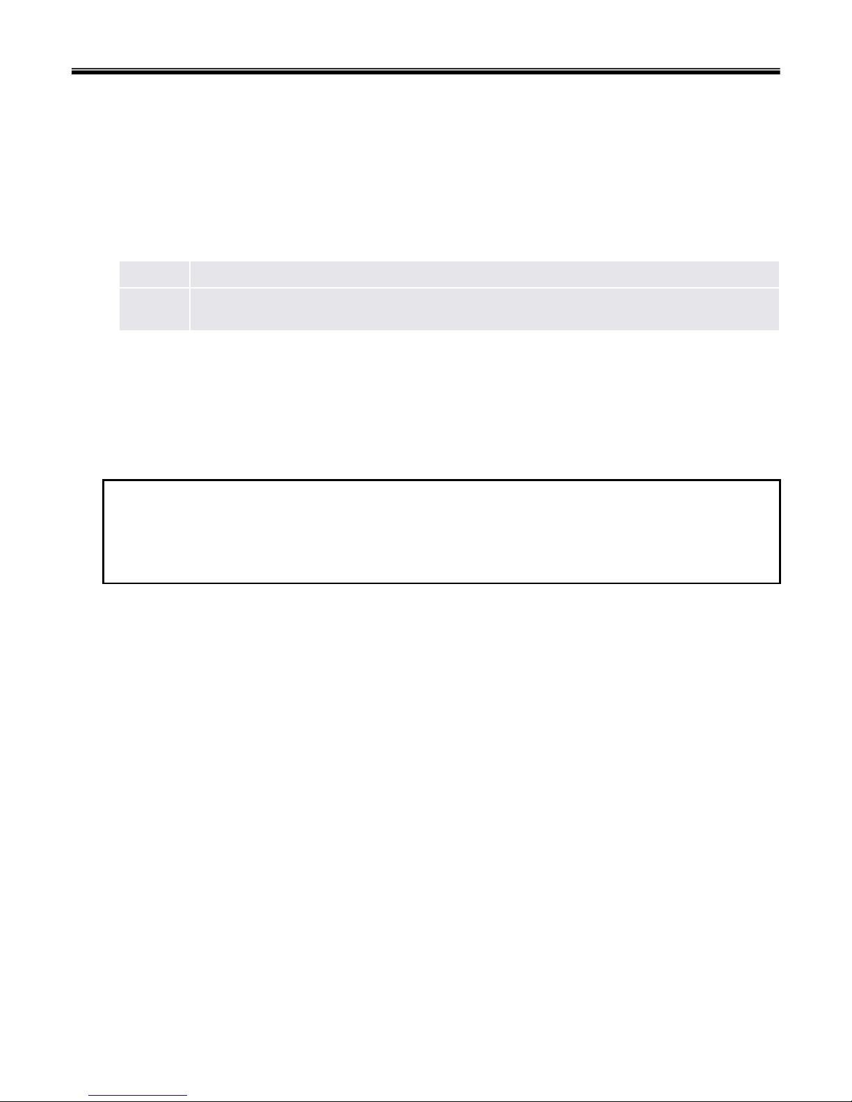
4. You can see the BIOS flash process as below
5. After flashing is completed, you can see the “PASS” on your screen, and reboot your PC

28
BIOS Setup
BIOS (Basic Input and Output System) Setup saves the system configuration in CMOS RAM, and
check the configurations during startup. Use the BIOS Setup Utility to change and save the system
environment, hardware configurations, power saving mode, etc.
· Open the BIOS Setup Utility in the following situations :
1. to change the BIOS setup
2. to replace the backup battery
3. system configuration error occurs
4. to change the boot order
5. to set/change a password
Press the power button.
When the LG logo appears on the screen, press and enter the BIOS Setup Utility.
Ch3. System information

29
Using the keys
The keys used in the BIOS Setup Utility and their functions are described at the bottom.
· , + : General Help
Display the descriptions of the keys used in the setup utility.
· , : Select Item
Navigate and select items in the setup utility. The selected item becomes highlighted.
· , : Select Menu
Move to another menu.
· / , : Change Values
Change the value of a selected item.
· : Load Default Configuration
Display Setup Confirmation window. Press Enter to load default configuration.
· : Select Sub-Menu
Some items have sub-menus. Display the sub-menu for a selected item.
· : Save and Exit
Display Setup Confirmation window. Press Enter to save and exit.
·: Exit
In a sub-menu, press Esc to move to the previous window. In Main menu, click Esc to move to Exit menu.
Ch3. System information

30
Main menu
Show System Overview information about BIOS version, CPU features, Memory size and setting of
System Time and Date.
Advanced menu
Configure IDE and USB settings.
Boot menu
Set up Boot Type and Boot Sequence
Ch3. System information
BIOS Setup Menu
Once you enter the BIOS Setup Utility, the Main menu will appear on the screen.
The main menu displays the system information, including the basic configuration.

31
Ch3. System information
Security menu
Install or clear Supervisor’s and User’s Password settings.
Exit menu
Choose decided status before leaving the BIOS menu.

32
System Time
This item allows you to set the system time. The system clock will go on no matter you shut down the PC
or get into sleep mode. The set format is [hour:minute:second].
System Date
This item allows you to set the system date. The date format is [day:month:date:year].
Day Day of the week, from Sun to Sat, which is determined by BIOS (read-only).
Month The month from 01 (January) to 12 (December).
Date The date from 01 to 31.
Year The year can be adjusted by users.
Main menu
Ch3. System information

33
Advanced Settings
Primary IDE Master/ Slave
The two items display the types of the primary master/slave IDE devices installed in the Notebook.
Press [Enter] to bring up a window showing the detailed information of the device, including the device
name, vendor, LBA mode, PIO mode and more.
USB Keyboard Legacy Support
Select Enabled to enable the legacy support for USB keyboard. Setting
options: Enabled, and Disabled.
Advanced menu
Ch3. System information

34
Intel(R) SpeedStep(tm) tech.
This item allows you to enable or disable Intel SpeedStep technology.
When set to Disabled, the system always operates in a conserve power mode (the processor works at
FSB400-600MHz or FSB533-800MHz).
If you want optimize the processor, set this item to Enabled, so that the processor’s speed will be
controlled by the use of your operating system and applications. Setting options: Enabled, and Disabled.
Ch3. System information

35
Boot Settings
Quiet Boot
This item enables you to show the vendor logo on the boot-up screen.
Settings options: Disabled and Enabled. The default setting is Enabled.
1st, 2nd and 3rd Boot Device
The three items allow you to set the sequence of boot devices where BIOS attempts to load the disk
operating system.
Ch3. System information
Boot menu

36
Security Settings
Change Supervisor/User Password
When you select the function, a message box will appear on the screen as below:
Security menu
Enter New Password
Type the password you want, up to six characters in length and press [Enter]. The password typed now
will replace any previously set password from CMOS memory. You may also press [ESC] to abort the
selection and not enter a password.
Ch3. System information
37
When the Supervisor Password is set, the new item User Access Level and Password Check will be
added in the menu. You can make further settings of access right in the User Access Level item. Setting
options: No Access, View Only, Limited and Full Access. The Password Check item is used to specify
the type of BIOS password protection that is implemented. Settings are described below:
A password prompt appears every time when the Notebook is powered on or when end users
try to run Setup.
Always
The password prompt appears only when end users try to run Setup.Setup
To clear a set password, just press [Enter] when you are prompted to enter the password. A message
box will show up confirming the password will be disabled. Once the password is disabled, the system
will boot and you can enter Setup without entering any password.
Note
About Supervisor Password and User Password
Supervisor Password allows the user to enter and change the settings of the setup menu; User Password
only allows the user to enter the setup menu, but do not have the right to make changes.
Ch3. System information

38
Exit Options
Save Changes and Exit
Save the changes you have made and exit the utility.
Discard Changes and Exit
Exit the utility without saving the changes you have made.
Discard Changes
Abandon your changes and reload the previous configuration before running the utility.
Load Optimal Defaults
Select this item to load the default settings for optimal system performance.
Exit menu
Ch3. System information

39
Note
If replacing a part (FRU) does not solve the problem, put the original part back in the computer.
Do not replace a non-defective FRU.
The symptom-to-part index in this section lists symptoms and errors and their possible causes.
The most likely cause is listed first.
Power system checkout
· To verify a symptom, do the following :
1. Power off the computer.
2. Remove the battery pack.
3. Connect the AC adapter.
4. Check that power is supplied when you power on the computer.
5. Power off the computer.
6. Disconnect the AC adapter and install the charged battery pack.
7. Check that the battery pack supplies power when you power on the computer.
· If you suspect a power problem, see the appropriate one of the following power supply checkouts :
1. Checking the AC adapter
2. Checking the operational charging
3. Checking the battery pack
4. Checking the backup battery
· Checking the AC adapter
If the power-on indicator does not turn on, check the power cord of the AC adapter for correct continuity
and installation.
If the computer does not charge during operation, go to “Checking operational charging.”
Chapter 4. Symptom-to-part index
Ch4. Symptom-to-part index

40
To check the AC adapter, do the following :
1. Unplug the AC adapter cable from the computer.
2. Measure the output voltage at the plug of the
AC adapter cable. See the following figure :
3. If the voltage is not correct, remove the power code
form AC adapter.
4. 10 seconds later, connect the power code, then measure the output voltage.
5. If the voltage is not correct, change the AC adapter.
2
1
Ground2
+18.05 ~ +19.951
Voltage (V dc)Pin
Ch4. Symptom-to-part index

41
· If the voltage is not correct, replace the AC adapter.
· If the voltage is acceptable, do the following :
1. Replace the system board.
2. If the problem persists, check the AC adapter whether it is correct product or not.
· Checking operational charging
1. To check whether the battery charges properly during operation, use a discharged battery pack or a
battery pack that has less than 50% of the total power remaining when installed in the computer.
Perform operational charging. If the battery status indicator or icon does not turn on, remove the battery
does not turn on, replace the battery pack.
2. If the charge indicator still does not turn on, replace the system board.
Then reinstall the battery pack.
Note
Noise from the AC adapter does not always indicate a defect.
Note
Do not charge battery pack, when its temperature is below 0 or above 75 .
· Checking the battery pack
1. Open the Power Meter window by clicking Start Control Panel Power Options and then;
check the total power remains. Battery charging does not start until the power Meter shows that less
than 95% of the total power remains; under this condition the battery pack can charge to 100% of its
capacity. This protects the battery pack from being overcharged or from having a shortened life.
2. To check the status of your batter, move your cursor to the Power Meter icon in the icon tray of the
Windows taskbar and wait for a moment (but do not click), and the percentage of battery power
remaining is displayed. To get detailed information about the battery, double-click the Power Meter icon.
Note
If the battery pack becomes hot, it may not be able to charge. Remove it from the computer and
Leave it at room temperature for a while. After it cools down, reinstall and recharge it.
Ch4. Symptom-to-part index

42
· The Characteristics of the battery pack
1. Self-discharge
The battery gradually loses its power over time without ever being used.
2. Periodic full discharge / charge
Frequent recharge of the battery pack can reduce the capacity of the battery pack. When this happens,
you can perform the full discharge / charge to improve the capacity. You should perform periodic full
discharge /charge once every 30~60 days.
You should always use the battery until its power is low; then fully charge the battery.
3. Trickle charge
If the temperature of the battery pack drops below 10 , the trickle charging begins.
The trickle charging may take 32 hours for the battery pack to be fully charged.
Ch4. Symptom-to-part index

43
· To check the battery pack, do the following :
1. Power off the computer.
2. Remove the battery pack and measure the voltage between battery terminals 1(-) and 5(+).
See the following figure :
+0V ~ +12.6V
(6 cell)
5
Ground(-)1
Voltage (V dc)Terminal
Note
Charging will take at least 3 hours.
3. If the voltage is still less than +11.1 V DC after recharging, replace the battery.
4. If the voltage is more than +11.1 V DC, measure the resistance between battery terminals 1 and 2.
The resistance must be 2 to 4 (typically 3 ).
5. If the resistance is not correct, replace the battery pack. If the resistance is correct, replace the system
board.
Ch4. Symptom-to-part index
Note
Battery is an expendable supplier, so its capacity and used time can be reduced by using the computer.
5(+) 4 3 2 1(-)
44
■ Repair Error Code
DOANBDOA
Product Issue
English Description Code
Others NB999
NTF From Customer Return NB998
No Trouble Found
System Auto Power Off NBP10
System Auto Power On NBP09
Can’t Power Off NBP08
System Can’t Shutdown Properly NBP07
No Display NBP06
System Hang Up In BIOS Utility NBP05
System Hang Up In POST NBP04
System Hang Up During Booting NBP03
System Can’t Power On NBP02
No Power NBP01
System / Power Issue
LCD Breakdown NBL10
LCD Panel Scrape NBL09
LCD Display Ripple NBL08
LCD Output Color is incorrect NBL07
LCD Display Garbage NBL06
LCD Output Color Is Not Even NBL05
Dark Dot On LCD Panel NBL04
Bright Dot On LCD Panel NBL03
LCD Display Abnormally NBL02
LCD Flash NBL01
LCD Issue
Ch4. Symptom-to-part index

45
HDD Performance Too LooNBH07
HDD Can't Create Partition NBH06
HDD Read / Write Error NBH05
HDD's Capacity Is Incorrect NBH04
HDD Breakdown NBH03
HDD Has Noise During Accessing Data NBH02
System Can't Detect HDD NBH01
HDD Issue
CD-ROM Vibrate Seriously While Rotating NBC08
CD Disc Comparability NBC07
CD-ROM Breakdown NBC06
CD-ROM Function Fail NBC05
CD-ROM Write Error NBC04
CD-ROM Read Error NBC03
CD-ROM Tray Can't Be Rejected NBC02
System Can't Detect CD-ROM Drive NBC01
ODD Issue
English Description Code
Memory Slot Fail NBD04
DRAM Breakdown NBD03
System Can’t Detect DRAM Module NBD02
DRAM Size Display Incorrectly NBD01
SO-DIMM Issue
Ch4. Symptom-to-part index

46
CPU Socket Fail NBCP3
CPU Breakdown NBCP2
CPU Speed Display Incorrectly NBCP1
CPU Issue
Can’t Power On When Use Battery Only NBB08
Battery Electric Leakage NBB07
Battery Capacity Display Abnormally In OS NBB06
Battery Life Is Too Short NBB05
Battery Breakdown NBB04
Battery’s Capacity Will Down To Empty Quickly NBB03
Battery Pack Can’t Charge To 100% NBB02
Battery Pack Can’t Charge NBB01
Battery Pack Issue
Keyboard Breakdown NBK04
Keyboard Button Drop Out NBK03
Keyboard Button Function Fail NBK02
Keyboard Can’t Work NBK01
Keyboard Issue
Touchpad Button Function Fail NBT04
Touchpad Surface Damage NBT03
Touchpad Can’t Work NBT02
System Can’t Detect Touchpad NBT01
Touchpad Issue
Ch4. Symptom-to-part index

47
Can't Connect To Internet Via WLAN NBI27
Wireless LAN Signal Is Weak Or Unstable NBI26
Wireless LAN Function Fail NBI25
Connect Quality Is Unstable Via RJ45 LAN Port NBI24
Can't Connect To Internet Via RJ45 LAN Port NBI23
MAC Address Is Empty NBI22
RJ45 <Network> Jack Function Fail NBI21
RJ11 <MODEM> Jack Function Fail NBI20
SPDIF-Out Function Fail NBI19
Line-In Jack Function Fail NBI18
Earphone-Out Jack Function Fail NBI17
Built-In MIC Function Fail NBI16
MIC-In Jack Function Fail NBI15
IrDA <Infaraed> Function Fail NBI14
PCMCIA Eject Switch Breakdown NBI13
PCMCIA Function Fail NBI12
Card Reader Function Fail NBI11
IEEE 1394 Port Function Fail NBI10
The TV Output Color Is Monochromatic NBI09
S-Video <TV-Out> Port Function Fail NBI08
VGA Port Function Fail NBI07
LPT Port Function Fail NBI06
USB Port Function Fail NBI05
Audio Volume Problem NBI04
Audio Noise NBI03
Internal Subwoofer Speaker Fail NBI02
Internal L/R Speaker Fail NBI01
I/O Issue
English Description Code
Ch4. Symptom-to-part index

48
RJ45 Jack Pin Bending NBI40
Blue Tooth Function Fail NBI39
LCM Display Abnormally NBI38
DVD Region Code Error NBI37
CPU Fan Fail NBI36
System Or NB Temperature Is Too High NBI35
Remote Controller Function Fail NBI34
Audio DJ Button Function Fail NBI33
Lid Switch Function Fail NBI32
AC Adapter Connector Fail NBI31
Status Indicator LED Fail NBI30
Quick Lanch Buttons <Instant Key> Function Fail NBI29
Connect Quality Is Unstable Via WLAN NBI28
I/O Issue
English Description Code
Ch4. Symptom-to-part index

49
System Can't Boot After Flash KBC Firmware NBFB8
System Can't Boot Result From Flash BIOS Fail NBFB7
System Can't Boot After Flash BIOS NBFB6
KBC Firmware Version Error NBFB5
Flash KBC Firmware Fail NBFB4
Can't Flash BIOS NBFB3
BIOS Version Error NBFB2
Flash BIOS Fail NBFB1
BIOS Issue
English Description Code
Can’t Recovery System Use Recovery CD NBS10
System Hang Up After Update Hardware Driver NBS09
System Random Hang Up NBS08
Bundle Software Problem NBS07
Take Too Long To Resume From S4 NBS06
Take Too Long To Resume From S3 NBS05
Take Too Long To Enter In OS NBS04
Can’t Install OS NBS03
OS (XP / 2000) Loading Fail NBS02
Microsoft Issue (Setting / Bug) NBS01
OS / Software / Driver Issue
Ch4. Symptom-to-part index

50
Sticker Loose Or Damage NBM10
AC Adapter Damage NBM09
OSD Bezel Damage NBM08
Palm Rest Damage NBM07
Hinge Cover Damage NBM06
Middle Cover Damage NBM05
Lower Case (D Casing) Damage NBM04
Top Case (C Casing) Damage NBM03
LCD Bezel (B Casing) Damage NBM02
LCD Cover (A Casing) Damage NBM01
Mechanism / Accessory Parts Issue
Change A/B/C/D Casing Or Other Mechanism Parts
NBUP6
Change Keyboard Language NBUP5
WLAN Module Upgrade NBUP4
So-Dimm Upgrade NBUP3
HDD Upgrade NBUP2
CPU Upgrade NBUP1
HW / ME Parts Upgrade Issue
Ch4. Symptom-to-part index

51
■ Repair RMA Code
Incorrect Operation By Customer NBR25
CPU Fan Damage NBR24
Remote Controller Damage NBR23
Wireless LAN Module Damage NBR22
Wireless LAN Antenna Damage NBR21
HW Driver Incorrect NBR20
Touchpad Cable Damage NBR19
Keyboard Cable Damage NBR18
Battery Connector Fail NBR17
Socket / Slot Damage NBR16
CD-ROM Doesn't Fix To NB NBR15
Inverter Cable Damage NBR14
Inverter Damage NBR13
Connector Damage NBR12
LVDS Cable Damage NBR11
SWAP New Touchpad NBR10
SWAP New Keyboard NBR09
SWAP New Battery Pack NBR08
SWAP New WLAN Module NBR07
SWAP New CPU NBR06
SWAP New DRAM Module NBR05
SWAP New OSD NBR04
SWAP New HDD NBR03
SWAP New LCD Panel NBR02
DOA Return And Change New Product NBR01
No Component, Replace MainboardNBMB2
Replace, SWAP MainboardNBMB1
No Problem Found NBN01
English Description Code
Ch4. Symptom-to-part index

52
Re-Paste New Sticker
NBR37
SWAP New PCMCIA Bracket
NBR36
SWAP New Mechanism Parts
NBR35
Blue Tooth Antenna Damage
NBR34
SWAP New Blue Tooth Module
NBR33
SWAP New AC Adapter
NBR32
Update BIOS
NBR31
CPU / VGA Thermal Module Or Thermal Pad Damage
NBR30
System is unstable After Install Not Suitable Software
NBR29
Customer's Device Is Poor Comparability With NB NBR28
Reinstall OS NBR27
Update KBC Firmware NBR26
English Description Code
Ch4. Symptom-to-part index

53
Indeterminate problems
· You are here because the diagnostic tests did not identify which adapter or device failed, wrong devices
are installed, a short circuit is suspected, or the system is inoperative.
Follow these procedures to isolate the failing FRU (do not isolate FRUs that have no defects).
· Verify that all attached devices are supported by the computer.
· Verify that the power supply being used at the time of the failure is operating correctly.
1. Power off the computer
2. Visually check each FRU for damage. Replace any damaged FRU.
3. Remove or disconnected all of the following devices :
a. Non-LG devices.
b. Printer, mouse, and other external devices.
c. Battery pack.
d. PC cards.
e. ODD (CD-ROM, Combo) drive or FDD drive in the Bay.
f. Hard-disk drive.
Note
Use the other memory card because it needs when operating computer.
4. Power on the computer.
5. Determine whether the problem has changed.
6. If the problem does not recur, reconnect the removed devices one at a time until you find the failing FRU.
7. If the problem remains, replace the following FRUs one at a time.
(do not replace a non-defective FRU)
a. LCD assembly (Check external monitor whether the same problem recurs or not).
b. Keyboard.
c. Keydeck (TouchPad and Scroll Button assembly).
d. System board.
Ch4. Symptom-to-part index

54
Chapter 5. Removing and replacing a part (FRU)
Note
As for the screw, every Torque 3 0.2Kgfcm(0.196Nm)
Danger
Before removing any FRU, power off the computer, unplug all power cords from electrical
outlets, remove the battery pack, and then disconnect any interconnecting cables.
Caution
Before the computer is powered on after FRU replacement, make sure that all screws, springs,
and other small parts are in place and are not loose inside the computer. Verify metal flakes can
cause electrical short circuits.
Ch5. Removing and replacing a part

55
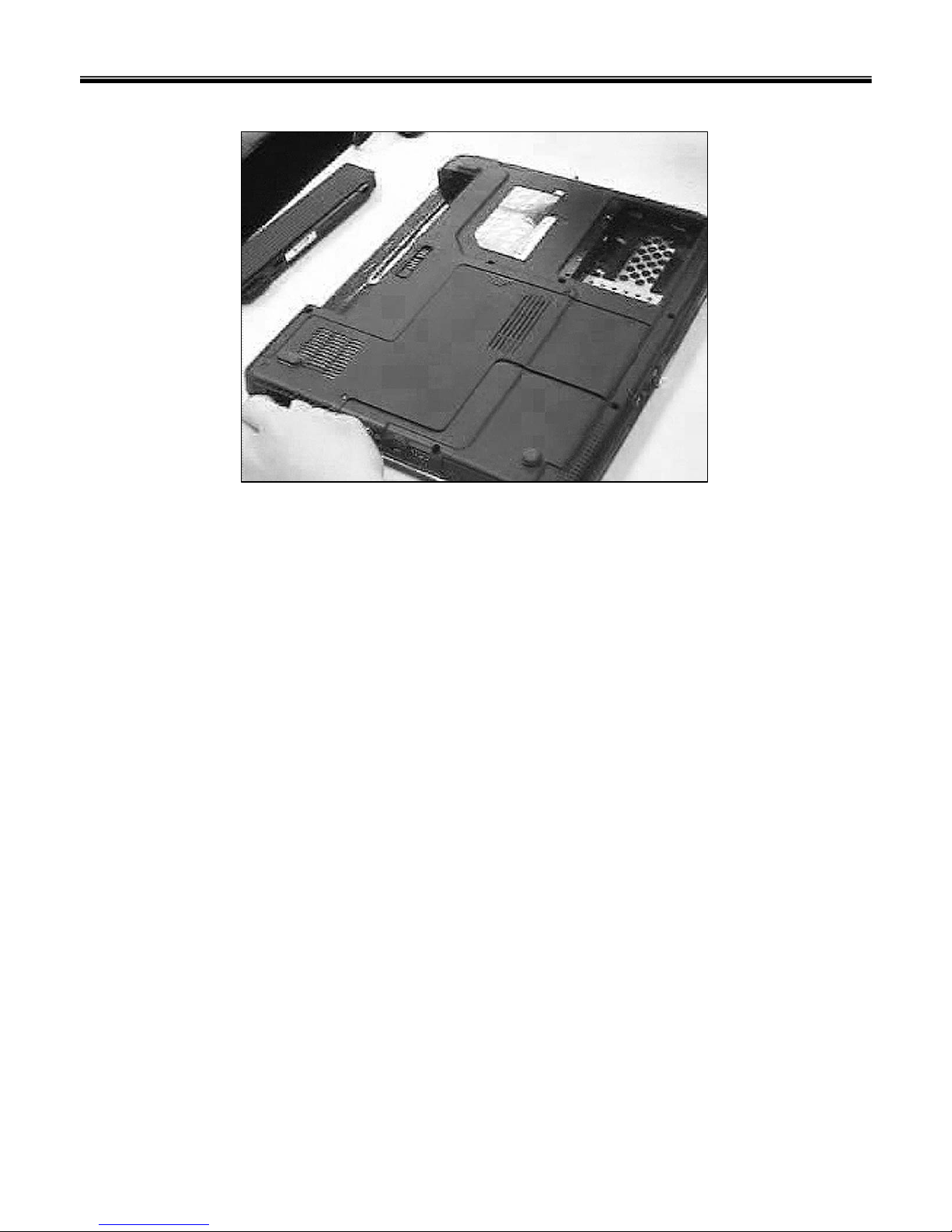
■ 1010 Battery Pack
1. Push the battery latch in the direction shown below; then slide the battery pack out of the slot.
Ch5. Removing and replacing a part

56
■ 1020 Hard Disk Drive
2M2.5 x L5.01SZZBZ4040A1
QtySpecificationFRU No.No.
1. Remove 2 screws.
※ Remove the following parts in order before replacing this part
a. Battery Pack(1010)
2. Remove HDD Cover.
Ch5. Removing and replacing a part

57
3. Remove HDD using a tag.
Ch5. Removing and replacing a part
58
Ch5. Removing and replacing a part

59
■ 1030 Memory
3M2.5 x L5.01SZZBZ4040A1
QtySpecificationFRU No.No.
1. Remove 3 screws.
※ Remove the following parts in order before replacing this part
a. Battery Pack(1010) b. Hard Disk Drive(1020)
2. Remove the CPU Cover.
Ch5. Removing and replacing a part

60
3. Remove the Memory.
Ch5. Removing and replacing a part
61
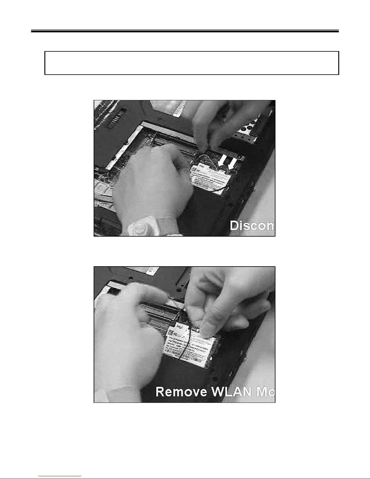
■ 1040 WLAN Card
1. Disconnect the WLAN Antenna Cable.
※ Remove the following parts in order before replacing this part
a. Battery Pack(1010) b. Hard Disk Drive(1020) c. Memory(1030)
2. Remove the WLAN Card.
Ch5. Removing and replacing a part

62
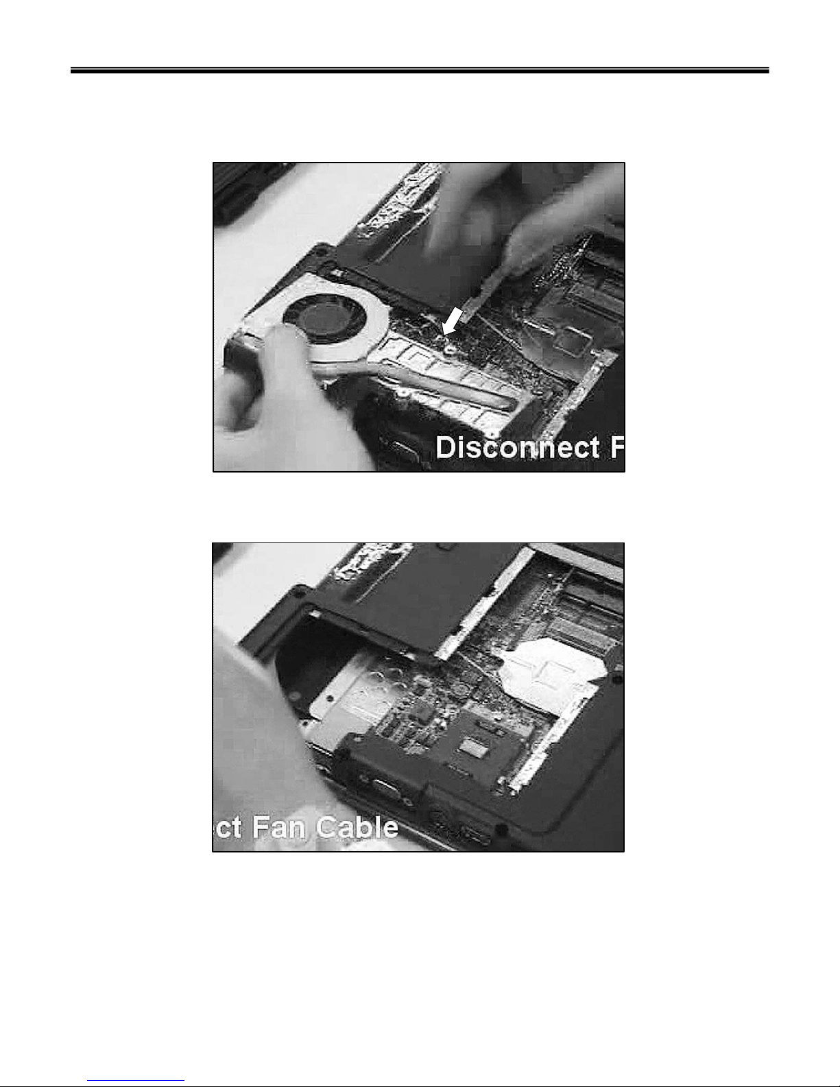
■ 1050 Fan Assembly
1. Loose Fan Assembly Spring Screw.
※ Remove the following parts in order before replacing this part
a. Battery Pack(1010) b. Hard Disk Drive(1020) c. Memory(1030) d. WLAN Card(1040)
Ch5. Removing and replacing a part
63
2. Disconnect the Fan Assembly connector.
3. Remove the Fan Assembly.
Ch5. Removing and replacing a part

64
■ 1060 CPU
1. Loose CPU screw, then remove the CPU.
※ Remove the following parts in order before replacing this part
a. Battery Pack(1010) b. Hard Disk Drive(1020) c. Memory(1030) d. WLAN Card(1040)
e. Fan Assembly
Ch5. Removing and replacing a part

65
■ 1070 ODD
1. Remove a screw.
※ Remove the following parts in order before replacing this part
a. Battery Pack(1010) b. Hard Disk Drive(1020) c. Memory(1030) d. WLAN Card(1040)
e. Fan Assembly(1050) f. CPU(1060)
1M2.5 x L5.01SZZBZ4040A1
QtySpecificationFRU No.No.
2. Remove the ODD.
Ch5. Removing and replacing a part

66
Ch5. Removing and replacing a part

67
■ 1080 Retainer
1. Remove the Middle Cover Mylar.
※ Remove the following parts in order before replacing this part
a. Battery Pack(1010) b. Hard Disk Drive(1020) c. Memory(1030) d. WLAN Card(1040)
e. Fan Assembly(1050) f. CPU(1060) g. ODD(1070)
2. Pull up the Retainer.
Ch5. Removing and replacing a part

68
3. Disconnect the Connector.
4. Remove the Retainer.
Ch5. Removing and replacing a part

69
■ 1090 Keyboard
1. Remove 2 Screws.
※ Remove the following parts in order before replacing this part
a. Battery Pack(1010) b. Hard Disk Drive(1020) c. Memory(1030) d. WLAN Card(1040)
e. Fan Assembly(1050) f. CPU(1060) g. ODD(1070) h. Retainer(1080)
2. Pull up the Keyboard.
2M2.0 x L3.01SZZBZ4042A1
QtySpecificationFRU No.No.
Ch5. Removing and replacing a part

70
3. Disconnect the Keyboard Connector, then remove the Keyboard.
Ch5. Removing and replacing a part

71
■ 1100 Display Module
1. Remove 4 screws.
※ Remove the following parts in order before replacing this part
a. Battery Pack(1010) b. Hard Disk Drive(1020) c. Memory(1030) d. WLAN Card(1040)
e. Fan Assembly(1050) f. CPU(1060) g. ODD(1070) h. Retainer(1080) i. Keyboard(1090)
2M2.5 x L8.01SZZBZ4046A1
QtySpecificationFRU No.No.
Ch5. Removing and replacing a part

72
2. Disconnect the LVDS / Inverter Cable.
Ch5. Removing and replacing a part

73
3. Remove the Display Module.
Ch5. Removing and replacing a part

74
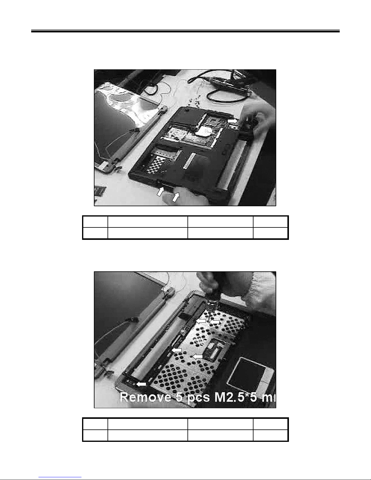
■ 1110 Keyboard Deck
1. Remove 10 screws.
※ Remove the following parts in order before replacing this part
a. Battery Pack(1010) b. Hard Disk Drive(1020) c. Memory(1030) d. WLAN Card(1040)
e. Fan Assembly(1050) f. CPU(1060) g. ODD(1070) h. Retainer(1080) i. Keyboard(1090)
j. Display Module(1100)
10M2.5 x L5.01SZZBZ4040A1
QtySpecificationFRU No.No.
Ch5. Removing and replacing a part
75
2. Remove 3 screws.
3M2.0 x L3.01SZZBZ4042A1
QtySpecificationFRU No.No.
3. Remove 5 screws.
5M2.5 x L5.01SZZBZ4040A1
QtySpecificationFRU No.No.
Ch5. Removing and replacing a part

76
4. Remove the Keydeck.
5. Disconnect the Touchpad Connector.
Ch5. Removing and replacing a part

77
6. Disconnect the Power Cable, then remove the Keydeck.
Ch5. Removing and replacing a part

78
■ 1120 Main Board
1. Remove a screw.
※ Remove the following parts in order before replacing this part
a. Battery Pack(1010) b. Hard Disk Drive(1020) c. Memory(1030) d. WLAN Card(1040)
e. Fan Assembly(1050) f. CPU(1060) g. ODD(1070) h. Retainer(1080) i. Keyboard(1090)
j. Display Module(1100) k. Keyboard Deck(1110)
1M2.5 x L5.01SZZBZ4040A1
QtySpecificationFRU No.No.
Ch5. Removing and replacing a part

79
2. Remove the Main Board.
3. Disconnect the DC-In / LAN / USB Cable.
Ch5. Removing and replacing a part

80
4. Disconnect the MDC Cable.
Ch5. Removing and replacing a part

81
5. Remove a screw.
6. Remove a screw.
1M2.5 x L5.01SZZBZ4040A1
QtySpecificationFRU No.No.
1M2.5 x L5.01SZZBZ4040A1
QtySpecificationFRU No.No.
Ch5. Removing and replacing a part

82
7. Remove the USB Board.
Ch5. Removing and replacing a part

83
1M2.5 x L5.01SZZBZ4040A1
QtySpecificationFRU No.No.
8. Remove a screw.
9. Remove the DC-In Board.
Ch5. Removing and replacing a part

84
Rev.BFL01
POWER
CORD
SP-021A+H03VVH2-F 2X0.75MM2+IS-033 I-SHENG KS 1800MM 2P CONN BLACK6410BM20307 NCABB
POWER
CORD
USA type, RoHS6410BC10706NCABB
KBDBrazilian Portuguese, RoHS3823BC0019ANKBDB
KBDHebrew, RoHS3823BC0008ANKBDB
KBDDanish, RoHS3823BC0013ANKBDB
KBDSwedish, RoHS3823BC0012ANKBDB
KBDNorwegian, RoHS3823BC0011ANKBDB
KBDCanadian French, RoHS3823BC0014ANKBDB
KBDTurkish, RoHS3823BC0015ANKBDB
KBDItalian, RoHS3823BC0016ANKBDB
KBDPortuguese, RoHS3823BC0010ANKBDB
KBDSpanish, RoHS3823BC0007ANKBDB
KBDFrench, RoHS3823BC0009ANKBDB
KBDGerman, RoHS3823BC0018ANKBDB
KBDHungarian, RoHS3823BC0017ANKBDB
KBDRussian, RoHS3823BC0004ANKBDB
KBDArabic, RoHS3823BC0006ANKBDB
KBDTaiwan, RoHS3823BC0005ANKBDB
KBDUS, RoHS3823BC0002ANKBDB
KBDUI, RoHS3823BC0003ANKBDB
KBDKorean layout, RoHS3823BC0001ANKBDB
ADAPTOR65W; FSP065-AAC6708BA0074ANACAB
BATTERY6cell (18651) Li-ion Battery ; LG-brand6911B00160ANBATB
INVERTERTWS-400-9152 6708BI0102ANINVB
MEMORYHynix, 512MB DDR2, M2OHY2G3H3410G1B5Z, RoHS0IMMR00247A
NMEMB
MEMORYSamsung, 512MB DDR2, TS64MSQ64V5J, RoHS0IMMR00233BNMEMB
MEMORYInfineon, 256MB DDR2, TS32MSQ64V5M, RoHS0IMMR00233ANMEMB
ODDSuper-Multi Assy2026B00029A NOODB
ODDCombo assy2029B09007A NOODB
HDD60GB; 4200rpm; MHV2060AT, RoHS6744C00160ANHDDB
HDD40GB; 4200rpm; MHV2040AT, RoHS6744C00137ANHDDB
LCD15" XGA TFT, B150XG02 v46304FAU026ANLCDB
CPUCeleron M 1.5GHz0IMCR02097BNCPUB
CPUDothan 1.73G0IMCR00009ANCPUB
REMARKSpecificationPart NoLocation
Chapter 6. Part lists
Ch6. Part lists

85
KBDKBD,DENMARK3823BC0013ANKBDB
KBDKBD,SWEDEN FINLAND3823BC0012ANKBDB
KBDKBD,NORWAY3823BC0011ANKBDB
KBDKBD,PORTUGESE3823BC0010ANKBDB
KBDKBD,FRENCH3823BC0009ANKBDB
KBDKBD,HEBREW3823BC0008ANKBDB
KBDKBD,SPANISH3823BC0007ANKBDB
KBDKBD,ARABIC3823BC0006ANKBDB
KBDKBD,TAIWAN3823BC0005ANKBDB
KBDKBD,RUSSIAN3823BC0004ANKBDB
KBDKBD,US INTER.3823BC0003ANKBDB
KBDKBD,ENGLISH3823BC0002ANKBDB
KBDKBD, KOREA3823BC0001ANKBDB
M/BMS-10161L1 20 EVT mainboard for MS-1016L1, RoHS, LG6871BMSIMABNMLBB
DUMMY,VER.0A-,MECH,NB,GE-7210A,DUMMYCARD PCMCIA,85.64*55.20*6.5mm,FOR MS-1016,701DE,3550BZ4012ANCVRF
DUMMY,VER.01-,MECH,NB,GE-7210A,DUMMYCARD NEWCARD,60.40*68.13*9.30mm,FOR MS-
1016,701DE,
3550BZ4013ANCVRE
FANCPU heat sink5901B09306ANFANB
BATTERYLi-ion 4400mAH, Panasonic Cell6911B00160ANBATB
ODDODD kits (super-multi?)2026B00029A NODDB
ODDODD kits (combo?)2029B09007A NODDB
COVER,VER.01-,MS1016_DOOR CPU_SUB_BLACK_MSI ,3581B10005ANCVRD
COVERMS1016_DOOR HDD_SUB_BLACK_MSI3581B10006ANCVRC
BOTTOM
CASE
,VER.01-,MS1016_LOWERCASE_SUB_BLACK_MSI ,3110BA0001ANCSEC
KBD DECKUppercase assy3111B0TT68ANCSEB
RETAINERMidcover assy
3581B10009ANCVRB
RETAINERMidcover assy3581B10008ANCVRB
M/BMP version6871BMSIMABNMLBB
FAN4600RPM, RoHS5901B09306ANFANB
ANTENNA,SYS/ANTENNA/HIGH-TEK/S79-0000190-H39/right antenna/For MS-1016,w/o scanningNANTC
ANTENNA,SYS/ANTENNA/HIGH-TEK/S79-0000180-H39/left WLAN antenna/For MS-1016,w/o scanningNANTB
LAN CARDMS-6833B-010, RoHS6718M000035NLANB
MDCMD560LMI-2(A)6871BG870AANMDCB
REMARKSpecificationPart NoLocation
Ch6. Part lists

86
SCREW,MECH,SCREW,PLAT,CROSS RECESS,M2X0.4,4mm,3mm,MACHINE SCREW,W ITH
NYLOK,PLATED NI,,FOR MS-1003,AISI-1018,
1SZZBZ4042ANSCRD
MAGNET,VER.0A-,MECH,NB,ND-FE-B,MAGNET,13*2.5*5.6mm,FOR MS-1016,,RoHS COMPLIANCE5016BZ3001ANSHTC
CABLE,INT COAXIAL CABLE,30,292mm,MB-30pin/ LCD-30pin,FOR MS-1016,,RoHS COMPLIANCE6850B30004ANCABD
ANTENNA,SYS/ANTENNA/HIGH-TEK/S79-0000180-H39/left WLAN antenna/For MS-1016,3551B09782ANBRKF
ANTENNA,SYS/ANTENNA/HIGH-TEK/S79-0000190-H39/right antenna/For MS-1016,3551B09783ANBRKE
CABLE,INT OTHER CABLE,INVERTER CABLE/ROUND/6/365mm/28AWG/FOR MS-1016,6850B06020ANCABC
INVERTER1408CA Inverter6708BI0102ANINVB
HINGEVER.01-,MECH,NB,SK7 AND SUS304 1/2H,HINGE ASSY L,,FOR MS-10164774BA0002ANHNGC
HINGEVER.01-,MECH,NB,SK7 AND SUS304 1/2H,HINGE ASSY R,,FOR MS-10164774BA0001ANHNGB
LCD BRACKETVER.02-,MECH,NB,SECC,BRACKET LCD L,L=262.2mm,FOR MS-10164810BA2002ANBRKD
LCD BRACKETBracket LCD –R LCD4810BA2001ANBRKC
REAR CASECover LCD sub assy3111B0TT70ANCVRI
REAR CASECover LCD sub assy3111B0TT69ANCVRI
SHEETFoil LCD assy3858BZ3051ANSHTB
LCDLCD6304FAU026ANLCDB
FRONT CASEBezel LCD3550BZ4014ANCSED
SCREW,MECH,SCREW,PLAT,CROSS RECESS,M3X0.5P,5mm,3.5mm,MACHINE SCREW,,PLATED
NI,,FOR MS-1006,AISI-1018,RoHS COMPLIANCE
1SZZBZ4047ANSCRF
BRACKET,VER.0A-,MECH,NB,SECC,BRACKET HDD,101.75*71.5*9.8mm,FOR MS-1016,FOR HDD HOLDER,4810BZ4103ANBRKB
SIELDINGMS1003_SHIELDING_HDD_ASSY3301B00573ANCVRH
HDDHDD6744C00137ANHDDB
HDDHDD6744C00160ANHDDB
HINGE CAP
Hinge Cap3550BM4221ANCVRG
KBDKBD,BRAZIL3823BC0019ANKBDB
KBDKBD,GERMAN3823BC0018ANKBDB
KBDKBD,HUNGARY3823BC0017ANKBDB
KBDKBD,ITALY3823BC0016ANKBDB
KBDKBD,TURKEY3823BC0015ANKBDB
KBDKBD,CANADIAN FRENCH3823BC0014ANKBDB
REMARKSpecificationPart NoLocation
Ch6. Part lists

87
SCREW,MECH,SCREW,PLAT,CROSS RECESS,M3X0.5P,5mm,3.5mm,MACHINE SCREW,,PLATED
NI,,FOR MS-1006,AISI-1018,RoHS COMPLIANCE
1SZZBZ4047A
SCREW,MECH,SCREW,PLAT,CROSS RECESS,M2.5X0.45,5mm,8mm,MACHINE SCREW,WITH
NYLOK,PLATED ZINC,BLACK,FOR MS-1002,AISI-1018,
1SZZBZ4046ANSCRE
SCREW,MECH,SCREW,PLAT,CROSS RECESS,M2X0.4,4mm,3mm,MACHINE SCREW,WITH
NYLOK,PLATED NI,,FOR MS-1003,AISI-1018,
1SZZBZ4042A
SCREW,MECH,SCREW,PLAT,CROSS RECESS,M2.5X0.45P,4.5mm,5mm,MACHINE SCREW,WITH
NYLOK,PLATING ZINC,BLACK,FOR MS-1004,AISI-1018,
1SZZBZ4041A
SCREW,MECH,SCREW,PLAT,CROSS RECESS,M2.5X0.45P,5mm,3mm,MACHINE SCREW,WITH
NYLOK,PLATED NI,,FOR MS-1003,AISI-1018,
1SZZBZ4040ANSCRB
SCREW,MECH,SCREW,PLAT,CROSS RECESS,M2.5X0.45P,4.5mm,5mm,MACHINE SCREW,WITH
NYLOK,PLATING ZINC,BLACK,FOR MS-1004,AISI-1018,
1SZZBZ4041ANSCRC
RUBBER,VER.01-,MECH,NB,SILICON,RUBBER LCD,1.6*5.5mm,FOR MS-1016,PANTONE 432C
W/ADHESIVE:T4000,RoHS COMPLIANCE
4850BZ4095ANCSNB
REMARKSpecificationPart NoLocation
Ch6. Part lists

Consult on page 71
Consult on page 56
※ For more information about screws, refer to ‘Chapter 5. Removing and replacing a part(FRU)’.
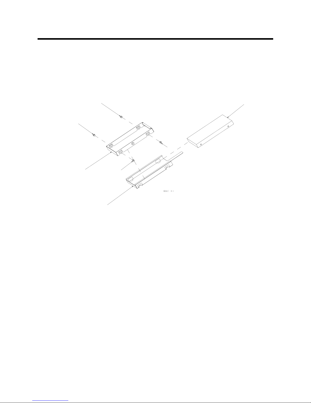
K1 Buffalo EXPLODED VIEW
2
NHDDB
NCVRH
NSCRF
NSCRF
NSCRF
NSCRF
NBRKB

K1 Buffalo EXPLODED VIEW
3
NBRKE
NCABC
NINVB
NCABD
NSHTB
NSCRC
NSCRD
NSCRD
NSCRD
NSCRD
NLCDB
NSCRC
NHNGB
NSCRC
NCVRI
NSCRC
NCSNB
NBRKC
NCSNB
NSCRC
NCSNB
NSCRC
NSCRC
NCSNB
NSCRC
NCSED
NBRKD
NSCRD
NSCRD
NSHTC
NSCRD
NSCRD
NSCRC
NSCRC
NHNGC
NSCRC
NSCRC
NBRKF

K1 Buffalo EXPLODED VIEW
4
Location LG P/N SPECIFICATION REMARKS
ˇ NCPUB 0IMCR00009A Dothan 1.73G CPU
NCPUB 0IMCR02097B Celeron M 1.5GHz CPU
NLCDB 6304FAU026A 15" XGA TFT, B150XG02 v4 LCD
NHDDB 6744C00137A 40GB; 4200rpm; MHV2040AT, RoHS HDD
NHDDB 6744C00160A 60GB; 4200rpm; MHV2060AT, RoHS HDD
NOODB 2029B09007A Combo assy ODD
NOODB 2026B00029A Super-Multi Assy ODD
NMEMB 0IMMR00233A Infineon, 256MB DDR2, TS32MSQ64V5M, RoHS MEMORY
NMEMB 0IMMR00233B Samsung, 512MB DDR2, TS64MSQ64V5J, RoHS MEMORY
NMEMB 0IMMR00247A Hynix, 512MB DDR2, M2OHY2G3H3410G1B5Z, RoHS MEMORY
NINVB 6708BI0102A TWS-400-9152 INVERTER
NBATB 6911B00160A 6cell (18651) Li-ion Battery ; LG-brand BATTERY
NACAB 6708BA0074A 65W; FSP065-AAC ADAPTOR
NKBDB 3823BC0001A Korean layout, RoHS KBD
NKBDB 3823BC0003A UI, RoHS KBD
NKBDB 3823BC0002A US, RoHS KBD
NKBDB 3823BC0005A Taiwan, RoHS KBD
NKBDB 3823BC0006A Arabic, RoHS KBD
NKBDB 3823BC0004A Russian, RoHS KBD
NKBDB 3823BC0017A Hungarian, RoHS KBD
NKBDB 3823BC0018A German, RoHS KBD
NKBDB 3823BC0009A French, RoHS KBD
NKBDB 3823BC0007A Spanish, RoHS KBD
NKBDB 3823BC0010A Portuguese, RoHS KBD
NKBDB 3823BC0016A Italian, RoHS KBD
NKBDB 3823BC0015A Turkish, RoHS KBD
NKBDB 3823BC0014A Canadian French, RoHS KBD
NKBDB 3823BC0011A Norwegian, RoHS KBD
NKBDB 3823BC0012A Swedish, RoHS KBD
NKBDB 3823BC0013A Danish, RoHS KBD
NKBDB 3823BC0008A Hebrew, RoHS KBD
NKBDB 3823BC0019A Brazilian Portuguese, RoHS KBD
NCABB 6410BC10706 USA type, RoHS POWER CORD
NCABB 6410BM20307 SP-021A+H03VVH2-F 2X0.75MM2+IS-033 I-SHENG KS 1800MM 2P CONN BLACK POWER CORD

K1 Buffalo EXPLODED VIEW
5
Location LG P/N SPECIFICATION REMARKS
NMDCB 6871BG870AA MD560LMI-2(A) MDC
NLANB 6718M000035 MS-6833B-010, RoHS LAN CARD
NANTB w/o scanning ,SYS/ANTENNA/HIGH-TEK/S79-0000180-H39/left WLAN antenna/For MS-1016, ANTENNA
NANTC w/o scanning ,SYS/ANTENNA/HIGH-TEK/S79-0000190-H39/right antenna/For MS-1016, ANTENNA
NFANB 5901B09306A 4600RPM, RoHS FAN
NMLBB 6871BMSIMAB MP version M/B
NCVRB 3581B10008A Midcover assy RETAINER
NCVRB 3581B10009A Midcover assy RETAINER
NCSEB 3111B0TT68A Uppercase assy KBD DECK
NCSEC 3110BA0001A ,VER.01-,MS1016_LOWERCASE_SUB_BLACK_MSI , BOTTOM CASE
NCVRC 3581B10006A MS1016_DOOR HDD_SUB_BLACK_MSI COVER
NCVRD 3581B10005A ,VER.01-,MS1016_DOOR CPU_SUB_BLACK_MSI , COVER
NODDB 2029B09007A ODD kits (combo?) ODD
NODDB 2026B00029A ODD kits (super-multi?) ODD
NBATB 6911B00160A Li-ion 4400mAH, Panasonic Cell BATTERY
NFANB 5901B09306A CPU heat sink FAN
NCVRE 3550BZ4013A ,VER.01-,MECH,NB,GE-7210A,DUMMYCARD NEWCARD,60.40*68.13*9.30mm, DUMMY
FOR MS-1016,701DE,
NCVRF 3550BZ4012A ,VER.0A-,MECH,NB,GE-7210A,DUMMYCARD PCMCIA,85.64*55.20*6.5mm, DUMMY
FOR MS-1016,701DE,
NMLBB 6871BMSIMAB MS-10161L1 20 EVT mainboard for MS-1016L1, RoHS, LG M/B
NKBDB 3823BC0001A KBD, KOREA KBD
NKBDB 3823BC0002A KBD,ENGLISH KBD
NKBDB 3823BC0003A KBD,US INTER. KBD
NKBDB 3823BC0004A KBD,RUSSIAN KBD
NKBDB 3823BC0005A KBD,TAIWAN KBD
NKBDB 3823BC0006A KBD,ARABIC KBD
NKBDB 3823BC0007A KBD,SPANISH KBD
NKBDB 3823BC0008A KBD,HEBREW KBD
NKBDB 3823BC0009A KBD,FRENCH KBD
NKBDB 3823BC0010A KBD,PORTUGESE KBD
NKBDB 3823BC0011A KBD,NORWAY KBD
NKBDB 3823BC0012A KBD,SWEDEN FINLAND KBD
NKBDB 3823BC0013A KBD,DENMARK KBD

K1 Buffalo EXPLODED VIEW
6
Location LG P/N SPECIFICATION REMARKS
NKBDB 3823BC0014A KBD,CANADIAN FRENCH KBD
NKBDB 3823BC0015A KBD,TURKEY KBD
NKBDB 3823BC0016A KBD,ITALY KBD
NKBDB 3823BC0017A KBD,HUNGARY KBD
NKBDB 3823BC0018A KBD,GERMAN KBD
NKBDB 3823BC0019A KBD,BRAZIL KBD
NCVRG 3550BM4221A Hinge Cap HINGE CAP
NHDDB 6744C00160A HDD HDD
NHDDB 6744C00137A HDD HDD
NCVRH 3301B00573A MS1003_SHIELDING_HDD_ASSY SIELDING
NBRKB 4810BZ4103A ,VER.0A-,MECH,NB,SECC,BRACKET HDD,101.75*71.5*9.8mm, BRACKET
FOR MS-1016,FOR HDD HOLDER,
NSCRF 1SZZBZ4047A ,MECH,SCREW,PLAT,CROSS RECESS,M3X0.5P,5mm,3.5mm,MACHINE SCREW
SCREW,,PLATED NI,,FOR MS-1006,AISI-1018,RoHS COMPLIANCE
NCSED 3550BZ4014A Bezel LCD FRONT CASE
NLCDB 6304FAU026A LCD LCD
NSHTB 3858BZ3051A Foil LCD assy SHEET
NCVRI 3111B0TT69A Cover LCD sub assy REAR CASE
NCVRI 3111B0TT70A Cover LCD sub assy REAR CASE
NBRKC 4810BA2001A Bracket LCD R LCD LCD BRACKET
NBRKD 4810BA2002A VER.02-,MECH,NB,SECC,BRACKET LCD L,L=262.2mm,FOR MS-1016 LCD BRACKET
NHNGB 4774BA0001A VER.01-,MECH,NB,SK7 AND SUS304 1/2H,HINGE ASSY R,,FOR MS-1016 HINGE
NHNGC 4774BA0002A VER.01-,MECH,NB,SK7 AND SUS304 1/2H,HINGE ASSY L,,FOR MS-1016 HINGE
NINVB 6708BI0102A 1408CA Inverter INVERTER
NCABC 6850B06020A ,INT OTHER CABLE,INVERTER CABLE/ROUND/6/365mm/28AWG/FOR MS-1016, CABLE
NBRKE 3551B09783A ,SYS/ANTENNA/HIGH-TEK/S79-0000190-H39/right antenna/For MS-1016, ANTENNA
NBRKF 3551B09782A ,SYS/ANTENNA/HIGH-TEK/S79-0000180-H39/left WLAN antenna/For MS-1016, ANTENNA
NCABD 6850B30004A ,INT COAXIAL CABLE,30,292mm,MB-30pin/ LCD-30pin,FOR MS-1016,, CABLE
RoHS COMPLIANCE
NSHTC 5016BZ3001A ,VER.0A-,MECH,NB,ND-FE-B,MAGNET,13*2.5*5.6mm,FOR MS-1016,,RoHS MAGNET
COMPLIANCE
NSCRD 1SZZBZ4042A ,MECH,SCREW,PLAT,CROSS RECESS,M2X0.4,4mm,3mm, SCREW
MACHINE SCREW,WITH NYLOK,PLATED NI,,FOR MS-1003,AISI-1018,

K1 Buffalo EXPLODED VIEW
7
Location LG P/N SPECIFICATION REMARKS
NCSNB 4850BZ4095A ,VER.01-,MECH,NB,SILICON,RUBBER LCD,1.6*5.5mm,FOR RUBBER
MS-1016,PANTONE 432C W/ADHESIVE:T4000,RoHS COMPLIANCE
NSCRC 1SZZBZ4041A ,MECH,SCREW,PLAT,CROSS RECESS,M2.5X0.45P,4.5mm,5mm, SCREW
MACHINE SCREW,WITH NYLOK,PLATING ZINC,BLACK,FOR MS-1004,
AISI-1018,
NSCRB 1SZZBZ4040A ,MECH,SCREW,PLAT,CROSS RECESS,M2.5X0.45P,5mm,3mm, SCREW
MACHINE SCREW,WITH NYLOK,PLATED NI,,FOR MS-1003,AISI-1018,
1SZZBZ4041A ,MECH,SCREW,PLAT,CROSS RECESS,M2.5X0.45P,4.5mm,5mm, SCREW
MACHINE SCREW,WITH NYLOK,PLATING ZINC,BLACK,FOR MS-1004,
AISI-1018,
1SZZBZ4042A ,MECH,SCREW,PLAT,CROSS RECESS,M2X0.4,4mm,3mm, SCREW
MACHINE SCREW,WITH NYLOK,PLATED NI,,FOR MS-1003,AISI-1018,
NSCRE 1SZZBZ4046A ,MECH,SCREW,PLAT,CROSS RECESS,M2.5X0.45,5mm,8mm, SCREW
MACHINE SCREW,WITH NYLOK,PLATED ZINC,BLACK,FOR MS-1002,
AISI-1018,
1SZZBZ4047A ,MECH,SCREW,PLAT,CROSS RECESS,M3X0.5P,5mm,3.5mm,MACHINE SCREW
SCREW,,PLATED NI,,FOR MS-1006,AISI-1018,RoHS COMPLIANCE
 Loading...