

Page 1

P/NO : AFN73178944 JUNE, 2009
MODEL : HB954TB (HB954TB-AD / SB94TB-C/F/S/W)SERVICE MANUAL
Internal Use Only
Website http://biz.lgservice.com
5.1Ch Blu-ray Receiver System
SERVICE MANUAL
MODEL : HB954TB
(HB954TB-AD / SB94TB-C/F/S/W)
CAUTION
BEFORE SERVICING THE UNIT, READ THE “SAFETY PRECAUTIONS”
IN THIS MANUAL.
Page 2

CONTENTS
SECTION 1 ........ SUMMARY
SECTION 2 ........ ELECTRICAL
SECTION 3 ........ CABINET & MAIN CHASSIS
SECTION 4 ........ HL-04P LOADER PART
SECTION 5 ........ REPLACEMENT PARTS LIST
1-1
Page 3

SECTION 1
SUMMARY
CONTENTS
PRODUCT SAFETY SERVICING GUIDELINES FOR BLU-RAY DISC PLAYER PRODUCTS .............. 1-3
SERVICING PRECAUTIONS .......................................................................................................................... 1-4
• GENERAL SERVICING PRECAUTIONS
• INSULATION CHECKING PRODEDURE
• ELECTROSTATICALLY SENSITIVE (ES) DEVICES
SERVICE INFORMATION FOR EEPROM .................................................................................................... 1-5
1. DVD PART
2. MICOM PART
SOFTWARE UPGRADE .................................................................................................................................. 1-7
SPECIFICATIONS ............................................................................................................................................ 1-8
1-2
Page 4
PRODUCT SAFETY SERVICING GUIDELINES
FOR BLU-RAY DISC PLAYER PRODUCTS
IMPORTANT SAFETY NOTICE
This manual was prepared for use only by properly trained audio-video service
technicians.
When servicing this product, under no circumstances should the original design be
modified or altered without permission from LG Corporation. All components should
be replaced only with types identical to those in the original circuit and their physical
location, wiring and lead dress must conform to original layout upon completion of
repairs.
Special components are also used to prevent x-radiation, shock and fire hazard.
These components are indicated by the letter “x” included in their component designators and are required to maintain safe performance. No deviations are allowed
without prior approval by LG Corporation.
Circuit diagrams may occasionally differ from the actual circuit used. This way,
implementation of the latest safety and performance improvement changes into the
set is not delayed until the new service literature is printed.
CAUTION : Do not attempt to modify this product in any way. Never perform cus-
tomized installations without manufacturer’s approval. Unauthorized modifications
will not only void the warranty, but may lead to property damage or user injury.
Service work should be performed only after you are thoroughly familiar with these
safety checks and servicing guidelines.
GRAPHIC SYMBOLS
The exclamation point within an equilateral triangle is intended to
alert the service personnel to important safety information in the
service literature.
The lightning flash with arrowhead symbol within an equilateral
triangle is intended to alert the service personnel to the presence of
noninsulated “dangerous voltage” that may be of sufficient magnitude
to constitute a risk of electric shock.
The pictorial representation of a fuse and its rating within an equilateral triangle is intended to convey to the service personnel the
following fuse replacement caution notice:
CAUTION : FOR CONTINUED PROTECTION AGAINST RISK
OF FIRE, REPLACE ALL FUSES WITH THE SAME TYPE AND
RATING AS MARKED NEAR EACH FUSE.
SERVICE INFORMATION
While servicing, use an isolation transformer for protection from AC line shock. After
the original service problem has been corrected, make a check of the following:
FIRE AND SHOCK HAZARD
1. Be sure that all components are positioned to avoid a possibility of adjacent
component shorts. This is especially important on items trans-ported to and from
the repair shop.
2. Verify that all protective devices such as insulators, barriers, covers, shields,
strain reliefs, power supply cords, and other hardware have been reinstalled per
the original design. Be sure that the safety purpose of the polarized line plug has
not been defeated.
3. Soldering must be inspected to discover possible cold solder joints, solder
splashes, or sharp solder points. Be certain to remove all loose foreign particles.
4. Check for physical evidence of damage or deterioration to parts and components, for frayed leads or damaged insulation (including the AC cord), and
replace if necessary.
5. No lead or component should touch a high current device or a resistor rated at 1
watt or more. Lead tension around protruding metal surfaces must be avoided.
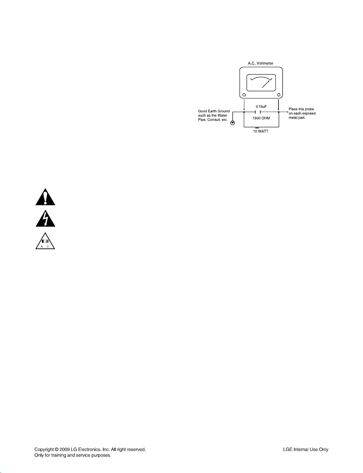
6. After reassembly of the set, always perform an AC leakage test on all exposed
metallic parts of the cabinet (the channel selector knobs, antenna terminals,
handle and screws) to be sure that set is safe to operate without danger of
electrical shock. DO NOT USE A LINE ISOLATION TRANSFORMER DURING
THIS TEST. Use an AC voltmeter having 5000 ohms per volt or more sensitivity
in the following manner: Connect a 1500 ohm, 10 watt resistor, paralleled by a
.15 mfd 150V AC type capacitor between a known good earth ground water pipe,
conduit, etc.) and the exposed metallic parts, one at a time. Measure the AC voltage across the combination of 1500 ohm resistor and .15 mfd capacitor. Reverse
the AC plug by using a non-polarized adaptor and repeat AC voltage measurements for each exposed metallic part. Voltage measured must not exceed 0.75
volts RMS. This corresponds to 0.5 milliamp AC. Any value exceeding this limit
constitutes a potential shock hazard and must be corrected immediately.
TIPS ON PROPER INSTALLATION
1. Never install any receiver in a closed-in recess, cubbyhole, or closely fitting shelf
space over, or close to, a heat duct, or in the path of heated air flow.
2. Avoid conditions of high humidity such as: outdoor patio installations where dew
is a factor, near steam radiators where steam leakage is a factor, etc.
3. Avoid placement where draperies may obstruct venting. The customer should
also avoid the use of decorative scarves or other coverings that might obstruct
ventilation.
4. Wall- and shelf-mounted installations using a commercial mounting kit must
follow the factory-approved mounting instructions. A product mounted to a shelf
or platform must retain its original feet (or the equivalent thickness in spacers) to
provide adequate air flow across the bottom. Bolts or screws used for fasteners
must not touch any parts or wiring. Perform leakage tests on customized installations.
5. Caution customers against mounting a product on a sloping shelf or in a tilted
position, unless the receiver is properly secured.
6. A product on a roll-about cart should be stable in its mounting to the cart.
Caution the customer on the hazards of trying to roll a cart with small casters
across thresholds or deep pile carpets.
7. Caution customers against using extension cords. Explain that a forest of extensions, sprouting from a single outlet, can lead to disastrous consequences to
home and family.
1-3
Page 5

SERVICING PRECAUTIONS
CAUTION: Before servicing the BLU-RAY DISC PLAYER covered by this service data and its supplements and addends,
read and follow the SAFETY PRECAUTIONS. NOTE: if
unforeseen circumstances create conflict between the following servicing precautions and any of the safety precautions in
this publications, always follow the safety precautions.
Remember Safety First :
General Servicing Precautions
1. Always unplug the BLU-RAY DISC PLAYER AC power cord
from the AC power source before:
(1) Removing or reinstalling any component, circuit board,
module, or any other assembly.
(2) Disconnecting or reconnecting any internal electrical
plug or other electrical connection.
(3) Connecting a test substitute in parallel with an electro-
lytic capacitor.
Caution : A wrong part substitution or incorrect polar-
ity installation of electrolytic capacitors may result in an
explosion hazard.
2. Do not spray chemicals on or near this BLU-RAY DISC
PLAYER or any of its assemblies.
3. Unless specified otherwise in this service data, clean electrical contacts by applying an appropriate contact cleaning
solution to the contacts with a pipe cleaner, cotton-tipped
swab, or comparable soft applicator.
Unless specified otherwise in this service data, lubrication of
contacts is not required.
4. Do not defeat any plug/socket B+ voltage interlocks with
whitch instruments covered by this service manual might be
equipped.
5. Do not apply AC power to this BLU-RAY DISC PLAYER
and / or any of its electrical assemblies unless all solidstate
device heat sinks are correctly installed.
6. Always connect the test instrument ground lead to an
appropriate ground before connecting the test instrument
positive lead. Always remove the test instrument ground
lead last.
Insulation Checking Procedure
Disconnect the attachment plug from the AC outlet and turn
the power on. Connect an insulation resistance meter (500V)
to the blades of the attachment plug. The insulation resistance
between each blade of the attachment plug and accessible
conductive parts (Note 1) should be more than 1Mohm.
Note 1 : Accessible Conductive Parts include Metal panels,
Input terminals, Earphone jacks,etc.
Electrostatically Sensitive (ES) Devices
Some semiconductor (solid state) devices can be damaged
easily by static electricity. Such components commonly are
called Electrostatically Sensitive (ES) Devices. Examples of
typical ES devices are integrated circuits and some field effect
transistors and semiconductor chip components.
The following techniques should be used to help reduce the
incidence of component damage caused by static electricity.
1. Immediately before handling any semiconductor component or semiconductor-equipped assembly, drain off any
electrostatic charge on your body by touching a known
earth ground. Alternatively, obtain and wear a commercially
available discharging wrist strap device, which should be
removed for potential shock reasons prior to applying power
to the unit under test.
2. After removing an electrical assembly equipped with ES
devices, place the assembly on a conductive surface such
as aluminum foil, to prevent electrostatic charge buildup or
exposure of the assembly.
3. Use only a grounded-tip soldering iron to solder or unsolder
ES devices.
4. Use only an anti-static solder removal device. Some solder
removal devices not classified as “anti-static” can generate
electrical charges sufficient to damage ES devices.
5. Do not use freon-propelled chemicals. These can generate
an electrical charge sufficient to damage ES devices.
6. Do not remove a replacement ES device from its protective
package until immediately before you are ready to install
it. (Most replacement ES devices are packaged with leads
electrically shorted together by conductive foam, aluminum
foil,or comparable conductive material).
7. Immediately before removing the protective material from
the leads of a replacement ES device, touch the protective
material to the chassis or circuit assembly into which the
device will be installed.
Caution: Be sure no power is applied to the chassis or cir-
cuit, and observe all other safety precautions.
8. Minimize bodily motions when handling unpackaged
replacement ES devices. (Normally harmless motion such
as the brushing together of your clothes fabric or the lifting
of your foot from a carpeted floor can generate static electricity sufficient to damage an ES device.)
1-4
Page 6
SERVICE INFORMATION FOR EEPROM
*APPLICABLE MODELS :
<A> HB954TB-AD.BINDLLK (LGEIL)
<B> HB954TB-AD.BMYSLLB (LGEML)
<A> 52 55 06 A6 00 05 2C 40
<B> 55 53 00 CA 00 05 2C 40
1. DVD PART
POWER ON
FLD “NO DISK” or “OPEN” status.
DETECT NEW EEPROM (OPTION EDIT SCREEN)
Remote control
Pause key-->1-->4-->7-->2 in order.
Press number 0~9, Press character
A~F (1~6 for a while)
Use arrow key (◀▲▶▼ ) to
move to appropriate position and
make changes
Press pause key once
Change will be applied
when power
OFF-->ON.
EEPROM Edit Table
Up/Down key : Change the EEPROM data
Left/Righr key : Move the Cursor
PAUSE key : Store the changed data and Exit the EEPROM Edit Table
1-5
Page 7
2. MICOM PART
NAME HEX
OP-0 09
OP-1 7A
OP-2 10
OP-3 C3
OP-4 00
POWER ON
FLD no disc status
Remote control ‘2’ + Front ‘STOP’
push same timing during 5s
FLD ‘OP-0….
Use arrow key (◀▲▶▼ ) to
move to appropriate position and
make changes
Press ENTER key once
FLD ‘write ok’ or ‘up ok’
Remote control ‘2’ + Front ‘STOP’
push same timing
DETECT NEW EEPROM
(OPTION EDIT SCREEN)
FLD display E2P CLR or EP CLR
Auto power off
1-6
Page 8

SOFTWARE UPGRADE
1. Copy D/L program to USB Memory.
- file name
: Backend program => LG_--.ROM ex) LG_HB_LV421BP.ROM
MICOM program => MICOM_--.HEX ex) MICOM_HB954.HEX / MICOM_HB354.HEX
TOUCH program => TOUCH_--.HEX ex) TOUCH_HB954.HEX / TOUCH_HB354.HEX
DSP program => DSP_--.HEX ex) DSP_HB954.HEX / DSP_HB354.HEX
2. Insert USB Memory. (at No disc status)
- If USB indicate normally, screen display pop up.
(Pop up message is “Do you want to update?”)
3. Press “ENTER” key.
- Program D/L start.
- Screen display popup message (“Updating….”).
- VFD display order
Backend program : 0 EXTRACT -> _PREPARE -> 0_INSTALL -> VERIFY-> FINALIZE -> UPDATE DONE
->POWEROFF
(download time : 2m 30s)
MICOM program : M-UPDATE
(download time : 40s~50s)
TOUCH program : T-UPDATE
(download time : 20s~30s)
DSP program : D-UPDATE
(download time : 13m)
4. SET auto power off.
1-7
Page 9

SPECIFICATIONS
SB94TB-F SB94TB-W
Type 2 Way 3 speaker 2 Way 2 speaker 2 Way 3 speaker 1 Way 1 speaker
Impedance 4Ω 4Ω 4Ω 3Ω
Rated Input Power 155W 155W 155W 225W
Max. Input power 310W 310W 310W 450W
Net Dimensions 330 x 1265 x 300mm 330 x 1265 x 300mm
(W x H x D)
Net Weight 5.0kg 4.7kg 1.0kg 7.3kg
SB94TB-S SB94TB-C
350 x 105 x 88mm 216 x 405 x 360mm
• GENERAL
Power requirements: Refer to main label .
Power consumption: 130W
Dimensions (W x H x D): Approx. 430 x 76 x 379mm without foot
Net Weight (Approx.): 4.8kg
Operating temperature: 41°F to 95°F (5°C to 35°C)
Operating humidity: 5% to 90%
• INPUTS/OUTPUTS
VIDEO OUT: 1.0V (p-p), 75Ω, sync negative, RCA jack x 1
COMPONENT VIDEO OUT: (Y) 1.0V (p-p), 75Ω, sync negative, RCA jack x 1
(Pb)/(Pr) 0.7V (p-p), 75Ω, RCA jack x 2
HDMI OUT (video/audio): 19 pin (HDMI standard, Type A)
HDMI IN (video/audio): 19 pin (HDMI standard, Type A)
ANALOG AUDIO IN: 2.0Vrms (1kHz, 0dB), 600Ω, RCA jack (L, R) x 1
DIGITAL IN (COAXIAL): 0.5V (p-p), 75Ω, RCA jack x 1
DIGITAL IN (OPTICAL): 3V (p-p), Optical jack x 1
PORT. IN: 0.5Vrms (3.5
• TUNER FM/AM
FM Tuning Range: 87.5 ~ 108.0MHz
:egnaR gninuT MA 520 ~ 1.710kHz
• AMPLIFIER
Stereo mode: 155W + 155W (4Ω at 1kHz, THD 10%)
Surround mode: Left+Right: 155W + 155W (THD 10%)
Center: 155W
Surround: 155W + 155W (4Ω at 1kHz, THD 10%)
Subwoofer: 225W (3Ω at 30Hz, THD 10%)
ø stereo jack)
• SYSTEM
Laser: Semiconductor laser, wavelength: 405nm / 650nm
Signal system: Standard PAL/NTSC color TV system
Frequency response: 20Hz to 20kHz (48kHz, 96kHz, 192kHz sampling)
Signal-to-noise ratio: More than 100dB (ANALOG OUT connectors only)
Harmonic distortion: Less than 0.008%
Dynamic range: More than 95dB
LAN port: Ethernet jack x 1, 10BASE-T/100BASE-TX
• SPEAKERS
Front Speaker Rear Speaker Center Speaker Passive Subwoofer
1-8
Page 10

SECTION 2
ELECTRICAL
CONTENTS
TRAINING MASTER FOR BLU-RAY (BD) .................................................................................................... 2-2
1. DISTORTED PICTURE ........................................................................................................................... 2-2
2. NO PICTURE .......................................................................................................................................... 2-7
3. PICTURE COLOR ................................................................................................................................. 2-12
4. NOISE/AUDIO PROBLEMS .................................................................................................................. 2-14
5. MISCELLANEOUS ................................................................................................................................ 2-17
6. BLU-RAY PLAYER ............................................................................................................................... 2-26
7. YouTube ................................................................................................................................................ 2-28
ELECTRICAL TROUBLESHOOTING GUIDE ............................................................................................. 2-30
1. SMPS PART CHECK ............................................................................................................................ 2-30
2. AMP PROTECTION .............................................................................................................................. 2-31
3. POWER KEY OPERATION .................................................................................................................. 2-32
4. FRONT BLOCK ..................................................................................................................................... 2-33
5. TOUCH KEY BLOCK ............................................................................................................................ 2-34
6. NO AUDIO CHECK ............................................................................................................................... 2-35
7. NO VIDEO CHECK ............................................................................................................................... 2-37
8. HDMI NO AUDIO/VIDEO CHECK (with HDMI IN) ............................................................................... 2-39
9. HDMI NO AUDIO/VIDEO CHECK (without HDMI IN) .......................................................................... 2-41
WAVEFORMS ................................................................................................................................................. 2-42
1. SYSTEM PART-1 .................................................................................................................................. 2-42
2. SYSTEM PART-2 (SYSTEM MEMORY) .............................................................................................. 2-43
3. VIDEO PART-1 (100% FULL COLOR-BAR) ........................................................................................ 2-44
4. VIDEO PART-2 (100% FULL COLOR-BAR) ........................................................................................ 2-45
5. HDMI PART .......................................................................................................................................... 2-46
6. MICOM AND MPEG I/F PART.............................................................................................................. 2-47
WIRING DIAGRAM ........................................................................................................................................ 2-49
BLOCK DIAGRAM ......................................................................................................................................... 2-51
CIRCUIT DIAGRAMS .................................................................................................................................... 2-53
1. SMPS CIRCUIT DIAGRAM .................................................................................................................. 2-53
2. CPU BCM7440-1 CIRCUIT DIAGRAM ................................................................................................. 2-55
3. CPU BCM7440-2 CIRCUIT DIAGRAM ................................................................................................. 2-57
4. DDR FLASH, CP CIRCUIT DIAGRAM ................................................................................................. 2-59
5. MICOM CIRCUIT DIAGRAM ................................................................................................................ 2-61
6. HDMI CIRCUIT DIAGRAM.................................................................................................................... 2-63
7. CPLD CIRCUIT DIAGRAM ................................................................................................................... 2-65
8. ADC/DIR CIRCUIT DIAGRAM .............................................................................................................. 2-67
9. DSP CIRCUIT DIAGRAM ..................................................................................................................... 2-69
10. POWER INTERFACE CIRCUIT DIAGRAM .......................................................................................... 2-71
11. IO INTERFACE CIRCUIT DIAGRAM ................................................................................................... 2-73
12. PWM CIRCUIT DIAGRAM .................................................................................................................... 2-75
13. AMP CIRCUIT DIAGRAM ..................................................................................................................... 2-77
14. FRONT CIRCUIT DIAGRAM ................................................................................................................ 2-79
15. POWER JUNCTION CIRCUIT DIAGRAM ............................................................................................ 2-81
16. POWER KEY CIRCUIT DIAGRAM ....................................................................................................... 2-83
17. IPOD CIRCUIT DIAGRAM .................................................................................................................... 2-85
18. TOUCH CIRCUIT DIAGRAM ................................................................................................................ 2-87
CIRCUIT VOLTAGE CHART ........................................................................................................................ 2-89
PRINTED CIRCUIT BOARD DIAGRAMS .................................................................................................... 3-93
1. MAIN P.C.BOARD ................................................................................................................................ 2-93
2. SMPS P.C.BOARD ............................................................................................................................... 2-97
3. AMP P.C.BOARD ................................................................................................................................ 2-101
4. FRONT P.C.BOARD ........................................................................................................................... 2-103
5. IPOD P.C.BOARD ............................................................................................................................... 2-103
6. TOUCH PAD P.C.BOARD .................................................................................................................. 2-103
2-1
Page 11
TRAINING MASTER FOR BLU-RAY (BD)
Objective: To provide clear and concise guidelines for customer service agents to handle calls on
box goods calls.
1. DISTORTED PICTURE
1-1. Lines on Picture
Distorted picture refers to the customer getting video, but there is a problem with the video.
What cables is
the customer using to
connect the BD?
YES
Is the TV set
to the correct input?
YES
Do lines appear when
watching multiple discs?
YES
Do lines appear when
watching a TV program?
NO
NO
NO
NO
Determine what cables the customer is using to connect
the BD to the TV and if connected properly. Refer to OM for
connections. Tighten any loose cables. Make sure the customer
is not connecting a BD to VCR or BD to DVD Recorder.
Copy protection can distort the picture on older DVD models.
Make sure the TV is on the correct input.
Turn TV off, then on to determine input.
Video when using composite, or component.
DVI when using DVI, and HDMI when using HDMI.
One disc displaying the issue is a problem with the disc.
Multiple discs displaying the problem could indicate the BD lens
needs to be cleaned. Recommend the customer use a lens
cleaner on the BD. A lens cleaner is available at any local
electronics retailer.
Lines appearing when watching a TV program indicates
an issue with the display. If the TV program is fine,
then connect the BD to another input on the display to
determine if the problem is following the BD.
YES
Do lines appear
when the BD is
connected to another TV?
YES
Has the customer tried
another set of cables?
NO
NO
Connect the BD to another TV and play a disc.
No lines during disc play back indicates a problem with the first TV.
Please refer to the owners manual for instructions on how to
connect the BD to a TV. If the BD has a problem on the
second TV, then see service chart for service information.
Have the customer try another set of cables. A bad cable can
also cause video problems. Test the cable with another device to
the TV to also determine if the TV is bad. If BD is problem,
please see service chart for service information.
2-2
Page 12

TRAINING MASTER FOR BLU-RAY (BD)
1-2. Ghost Picture
Distorted picture refers to the customer getting video, but there is a problem with the video.
What cables is the customer
using to connect the BD?
YES
Is the TV set to
the correct input?
YES
Do ghosting appear when
watching multiple discs?
YES
Do lines appear when
watching a TV program?
NO
NO
NO
NO
Determine what cables the customer is using to connect the BD to
the TV and if connected properly. Refer to OM for connections.
Tighten any loose cables. Make sure the customer is not connecting a
BD to VCR or BD to DVD Recorder. Copy protection can distort
the picture on older VCR models.
Make sure the TV is on the correct input. Turn TV off,
then on to determine input. Video when using composite,
or component. DVI when using DVI, and HDMI when using HDMI.
One disc displaying the issue is a problem with the disc.
Multiple discs displaying the problem could indicate the BD lens
needs to be cleaned. Recommend the customer use a lens cleaner
on the BD. A lens cleaner is available at any local electronics retailer.
Ghosting appearing when watching a TV program indicates an
issue with the display. If the TV program is fine, then connect
the BD to another input on the display to determine
if the problem is following the BD.
YES
Does ghosting
appear when the BD is
connected to another TV?
YES
Has the customer tried
another set of cables?
NO
NO
Connect the BD to another TV and play a disc.
No ghosting during disc play back indicates a problem with the first TV.
Please refer to the owners manual for instructions on how to
connect the BD to a TV. If the BD has a problem on the second TV,
then see service chart for service information.
Have the customer try another set of cables. A bad cable can
also cause video problems. Test the cable with another device to
the TV to also determine if the TV is bad. If BD is problem,
please see service chart for service information.
2-3
Page 13
TRAINING MASTER FOR BLU-RAY (BD)
1-3. Rolling Picture
Distorted picture refers to the customer getting video, but there is a problem with the video.
What cables is the customer
using to connect the BD?
YES
Is the TV set to
the correct input?
YES
Does rolling appear when
watching multiple discs?
YES
Does rolling appear when
watching a TV program?
NO
NO
NO
NO
Determine what cables the customer is using to connect the BD to
the TV and if connected properly. Refer to OM for connections.
Tighten any loose cables. Make sure the customer is not connecting
a BD to VCR or BD to DVD Recorder. Copy protection can distort
the picture on older VCR models.
Make sure the TV is on the correct input. Turn TV off,
then on to determine input. Video when using composite,
or component. DVI when using DVI, and HDMI when using HDMI.
One disc displaying the issue is a problem with the disc.
Multiple discs displaying the problem could indicate the BD lens
needs to be cleaned. Recommend the customer use a lens cleaner
on the BD. A lens cleaner is available at any local electronics retailer.
Rolling appearing when watching a TV program indicates
an issue with the display. If the TV program is fine, then connect
the BD to another input on the display to determine if the problem
is following the BD.
YES
Does rolling appear
when the BD is connected to
another TV?
YES
Has the customer tried
another set of cables?
NO
NO
Connect the BD to another TV and play a disc. No lines during disc play
back indicates a problem with the first TV. Please refer to the owners
manual for instructions on how to connect the BD to a TV. If the BD has a
problem on the second TV, then see service chart for service information.
Have the customer try another set of cables. A bad cable can also
cause video problems. Test the cable with another device to the TV
to also determine if the TV is bad. If BD is problem,
please see service chart for service information.
2-4
Page 14
TRAINING MASTER FOR BLU-RAY (BD)
1-4. Shaky Picture
Distorted picture refers to the customer getting video, but there is a problem with the video.
What cables is the customer
using to connect the BD?
YES
Is the TV set to
the correct input?
YES
Does shaking appear when
watching multiple discs?
YES
Does shaking appear when
watching a TV program?
NO
NO
NO
NO
Determine what cables the customer is using to connect the BD to
the TV and if connected properly. Refer to OM for connections.
Tighten any loose cables. Make sure the customer is not connecting a
BD to VCR or BD to DVD Recorder. Copy protection can distort
the picture on older VCR models.
Make sure the TV is on the correct input. Turn TV off, then on
to determine input. Video when using composite, or component.
DVI when using DVI, and HDMI when using HDMI.
One disc displaying the issue is a problem with the disc.
Multiple discs displaying the problem could indicate the BD lens
needs to be cleaned. Recommend the customer use a lens cleaner
on the BD. A lens cleaner is available at any local electronics retailer.
Shaking appearing when watching a TV program indicates
n issue with the display. If the TV program is fine, then connect
the BD to another input on the display to determine if the problem
is following the BD.
YES
Does shaking appear
when the BD is connected to
another TV?
YES
Has the customer tried
another set of cables?
NO
NO
Connect the BD to another TV and play a disc. No shaking during
disc play back indicates a problem with the first TV. Please refer to
the owners manual for instructions on how to connect the BD to a TV.
If the BD has a problem on the second TV,
then see service chart for service information.
Have the customer try another set of cables. A bad cable can
also cause video problems. Test the cable with another device to
the TV to also determine if the TV is bad. If BD is problem,
please see service chart for service information.
2-5
Page 15

TRAINING MASTER FOR BLU-RAY (BD)
1-5. Blurry Picture
Distorted picture refers to the customer getting video, but there is a problem with the video.
What cables is the customer
using to connect the BD?
YES
Is the TV set to
the correct input?
YES
Does blurriness appear when
watching multiple discs?
YES
Does blurriness appear when
watching a TV program?
NO
NO
NO
NO
Determine what cables the customer is using to connect the BD to
the TV and if connected properly. Refer to OM for connections.
Tighten any loose cables. Make sure the customer is not connecting
a BD to VCR or BD to DVD Recorder. Copy protection can distort
the picture on older VCR models.
Make sure the TV is on the correct input. Turn TV off,
then on to determine input. Video when using composite, or component.
DVI when using DVI, and HDMI when using HDMI.
One disc displaying the issue is a problem with the disc.
Multiple discs displaying the problem could indicate the BD lens
needs to be cleaned. Recommend the customer use a lens cleaner on
the BD. A lens cleaner is available at any local electronics retailer.
Blurriness appearing when watching a TV program indicates an
issue with the display. If the TV program is fine, then connect
the BD to another input on the display to determine if the problem
is following the BD.
YES
Does blurriness appear
when the BD is connected to
another TV?
YES
Has the customer tried
another set of cables?
NO
NO
Connect the BD to another TV and play a disc. No blurriness
during disc play back indicates a problem with the first TV.
Please refer to the owners manual for instructions on how to connect
the BD to a TV. If the BD has a problem on the second TV,
then see service chart for service information.
Have the customer try another set of cables.
A bad cable can also cause video problems. Test the cable with another
device to the TV to also determine if the TV is bad. If BD is problem,
please see service chart for service information.
2-6
Page 16
TRAINING MASTER FOR BLU-RAY (BD)
2. NO PICTURE
2-1. Black Screen
The entire screen is black.
What cables is the customer
using to connect the BD?
YES
Is the TV set to
the correct input?
YES
Is the customer able to
watch TV programming?
YES
Can the customer connect
the BD to another TV?
NO
NO
NO
NO
Determine what cables the customer is using to connect the BD to
the TV and if connected properly. Refer to OM for connections.
Tighten any loose cables. Make sure the customer is not connecting a
BD to VCR or BD to DVD Recorder. Copy protection can distort
the picture on older VCR models.
Make sure the TV is on the correct input. Turn TV off,
then on to determine input. Video when using composite,
or component. DVI when using DVI, and HDMI when using HDMI.
If the customer is not able to watch television then he may have a
problem with his television, especially if the cable signal comes
through on a different input. If the customer can not get a TV program,
then he still may have a problem with the particular input on his TV.
Have the customer connect the BD to another TV in order to
determine if the problem is the BD or the TV. Refer to the OM for
connections assistance. If the BD works on the second TV,
then the customer has a problem with his TV.
YES
Has the customer tried
another set of cables?
NO
Have the customer try another set of cables. A bad cable can
also cause video problems. Test the cable with another device to
the TV to also determine if the TV is bad. If BD is problem,
please see service chart for service information.
2-7
Page 17
TRAINING MASTER FOR BLU-RAY (BD)
2-2. Blue Screen
The entire screen is a solid blue color.
What cables is the customer
using to connect the BD?
YES
Is the TV set to
the correct input?
YES
Is the customer able to
watch TV programming?
YES
Can the customer connect
the BD to another TV?
NO
NO
NO
NO
Determine what cables the customer is using to connect the BD
to the TV and if connected properly. Refer to OM for connections.
Tighten any loose cables. Make sure the customer is not connecting a
BD to VCR or BD to DVD Recorder. Copy protection can distort
the picture on older VCR models.
Make sure the TV is on the correct input.
Turn TV off, then on to determine input. Video when using composite,
or component. DVI when using DVI, and HDMI when using HDMI.
If the customer is not able to watch television then he may have a
problem with his television, especially if the cable signal comes
through on a different input. If the customer can not get a TV program,
then he still may have a problem with the particular input on his TV.
Have the customer connect the BD to another TV in order to
determine if the problem is the BD or the TV. Refer to the OM for
connections assistance. If the BD works on the second TV,
then the customer has a problem with his TV.
YES
Has the customer tried
another set of cables?
NO
Have the customer try another set of cables. A bad cable can also
cause video problems. Test the cable with another device to
the TV to also determine if the TV is bad. If BD is problem,
please see service chart for service information.
2-8
Page 18

TRAINING MASTER FOR BLU-RAY (BD)
2-3. Snowy Screen
A snowy picture is when black and white dots are all over the screen.
What cables is the customer
using to connect the BD?
YES
Is the TV set to
the correct input?
YES
Is the customer able to
watch TV programming?
YES
Can the customer connect
the BD to another TV?
NO
NO
NO
NO
Determine what cables the customer is using to connect the BD
to the TV and if connected properly. Refer to OM for connections.
Tighten any loose cables. Make sure the customer is not connecting a
BD to VCR or BD to DVD Recorder. Copy protection can distort
the picture on older VCR models.
Make sure the TV is on the correct input. Turn TV off,
then on to determine input. Video when using composite,
or component. DVI when using DVI, and HDMI when using HDMI.
If the customer is not able to watch television then he may
have a problem with his television, especially if the cable signal comes
through on a different input. If the customer can not get a TV program,
then he still may have a problem with the particular input on his TV.
Have the customer connect the BD to another TV in order to
determine if the problem is the BD or the TV. Refer to the OM for
connections assistance. If the BD works on the second TV,
then the customer has a problem with his TV.
YES
Has the customer tried
another set of cables?
NO
Have the customer try another set of cables. A bad cable can
also cause video problems. Test the cable with another device to
the TV to also determine if the TV is bad. If BD is problem,
please see service chart for service information.
2-9
Page 19

TRAINING MASTER FOR BLU-RAY (BD)
2-4. No Signal
A “no signal” message appears on the screen of the display.
What cables is the customer
using to connect the BD?
YES
Is the TV set to the
correct input?
YES
Is the customer able to
watch TV programming?
YES
Can the customer connect
the BD to another TV?
NO
NO
NO
NO
Determine what cables the customer is using to connect the BD
to the TV and if connected properly. Refer to OM for connections.
Tighten any loose cables. Make sure the customer is not connecting a
BD to VCR or BD to DVD Recorder. Copy protection can distort
the picture on older VCR models.
Make sure the TV is on the correct input. Turn TV off,
then on to determine input. Video when using composite,
or component. DVI when using DVI, and HDMI when using HDMI.
If the customer is not able to watch television then he may have a
problem with his television, especially if the cable signal comes
through on a different input. If the customer can not get a TV program,
then he still may have a problem with the particular input on his TV.
Have the customer connect the BD to another TV in order to
determine if the problem is the BD or the TV. Refer to the OM for
connections assistance. If the BD works on the second TV,
then the customer has a problem with his TV.
YES
Has the customer tried
another set of cables?
NO
Have the customer try another set of cables. A bad cable
can also cause video problems. Test the cable with another device to
the TV to also determine if the TV is bad. If BD is problem,
please see service chart for service information.
2-10
Page 20
TRAINING MASTER FOR BLU-RAY (BD)
2-5. Invalid Format or Format Not Supported
Is the customer using a
digital cable connection?
YES
Is the customer using an
analog cable connection?
YES
Is the display
HDCP compliant?
YES
Has the customer tried the
device on another display?
NO
NO
NO
NO
Make sure the customer’s simultaneously connecting analog component
cable with HDMI cable. And then If Copy Protected Disc is playing back,
analog component output is no picture. Only when the analog output
is 576i, you can see the picture. In case of No Copy Protected Disc,
you can see the picture regardless of the resolution.
Customer’s using an DVI, or HDMI cable connection need to set
the resolution on the product above 480i. HDMI, DVI connections
can not process a 576i resolution. They can only process a 576p,
720p, 1080i, or 1080p resolution.
Make sure the display is HDCP compliant when using a DVI or
HDMI connection. A lack of HDCP compliancy on the display may
cause an invalid format or format not supported message to appear.
It can also cause a copy protection OSD to appear.
Ask the customer to connect the device to another display.
If the device starts working, then the problem may be the original display.
The customer will need to troubleshoot the display. If the device
still does not work, then the problem may be the device or the cable.
YES
Has the customer tried
another cable?
NO
Ask the customer to replace the cable between the device and display.
If the problem is corrected, then the problem was with the cable.
If the problem continues, then the device is the problem.
Set up service according to in warranty or out of warranty procedures.
2-11
Page 21

TRAINING MASTER FOR BLU-RAY (BD)
3. PICTURE COLOR
3-1. No Color
The video displays no color and only shows in black and white.
What cables is the customer
using to connect the BD?
YES
Is the TV set to the
correct input?
YES
Does color appear when
watching multiple discs?
YES
Does color appear when
watching a TV program?
NO
NO
NO
NO
Determine what cables the customer is using to connect the BD
to the TV and if connected properly. Refer to OM for connections.
Tighten any loose cables. Make sure the customer is not connecting a
BD to VCR. Copy protection can distort the picture on older VCR models.
Make sure the TV is on the correct input according to the
connections in use. Video when using composite, or component.
DVI when using DVI, and HDMI when using HDMI.
One disc displaying the issue is a problem with the disc.
Make sure the discs the customer is using are compatible with the
BD by checking “playable discs” in the owners manual.
Multiple discs displaying the problem indicates a problem with
the BD player.
If the cable or satellite programming is connected through
another input and the customer does not get color, the customer has a
problem with his television. If a TV program does have the color,
the problem may be the BD player, the cables being used,
or the TV itself.
YES
Does color appear
when the BD is
connected to another TV?
YES
Has the customer tried
another set of cables?
NO
NO
Connect the BD to another TV and play a disc. Good color during
disc play back indicates a problem with the first TV. Please refer to the
owners manual for instructions on how to connect the BD to a TV.
If the BD has a problem on the second TV, then see service chart for
service information.
Have the customer try another set of cables. A bad cable can
also cause video problems. Test the cable with another device to
the TV to also determine if the TV is bad. If the BD is the problem,
please see service chart for service information.
2-12
Page 22

TRAINING MASTER FOR BLU-RAY (BD)
3-2. Poor Color
The color is poor. Examples would be washed out colors, colors bleeding into one another, or a solid tint to
a screen.
What cables is the customer
using to connect the BD?
YES
Is the TV set to the
correct input?
YES
Is color fine when watching
multiple discs?
YES
Is color fine when watching
a TV program?
NO
NO
NO
NO
Determine what cables the customer is using to connect the BD to
the TV and if connected properly. Refer to OM for connections.
Tighten any loose cables. Make sure the customer is not connecting a
BD to VCR. Copy protection can distort the picture on older VCR models.
Make sure the TV is on the correct input according to the
connections in use. Video when using composite, or component.
DVI when using DVI, and HDMI when using HDMI.
One disc displaying the issue is a problem with the disc.
Make sure the discs the customer is using are compatible with the BD
by checking “playable discs” in the owners manual. Multiple discs
displaying the problem indicates a problem with the BD player.
If the cable or satellite programming is connected through another
input and the customer does not get color, the customer has a problem
with his television. If a TV program does have the color, the problem
may be the BD player, the cables being used, or the TV itself.
YES
Is color fine when the BD is
connected to another TV?
YES
Has the customer tried
another set of cables?
NO
NO
Connect the BD to another TV and play a disc. Good color during
disc play back indicates a problem with the first TV. Please refer to the
owners manual for instructions on how to connect the BD to a TV.
If the BD has a problem on the second TV, then see service
chart for service information.
Have the customer try another set of cables. A bad cable
can also cause video problems. Test the cable with another device to
the TV to also determine if the TV is bad. If the BD is the problem,
please see service chart for service information.
2-13
Page 23
TRAINING MASTER FOR BLU-RAY (BD)
4. NOISE/AUDIO PROBLEMS
4-1. No Audio
The customer is not able to get audio.
What cables is the customer
using to connect the BD?
YES
Is the customer
able to see video?
YES
Does issue occur on
more than one disc?
YES
Problem occur when
watching TV program?
NO
NO
NO
NO
Determine what cables the customer is using to connect the BD
to the TV and if connected properly. Refer to OM for connections.
Tighten any loose cables. Make sure the customer has audio cables
connected if using an HDMI to DVI adapter or video-only cables
(DVI, component, etc).
Make sure the customer has not routed video
and audio to separate inputs.
Problem occurring on one disc indicates a problem with the disc.
Problem occurring on multiple discs could indicate a lens cleaner
is needed. The customer can purchase a lens cleaner at any
electronics retailer.
No audio from a TV program on a different channel or input means
there is a problem with the television. If a TV program does have
the audio, the problem may be the BD player, the cables being used,
or the TV itself.
YES
Does the problem occur
when BD is connected to
another TV?
YES
Has the customer tried
another set of cables?
NO
NO
Audio is fine when the BD is connected to another TV
indicates the problem is with the television. Refer to
the owners manual for assistance with connecting BD to another TV.
Have the customer try another set of cables. A bad cable can also
cause audio problems. Test the cable with another device to
the TV to also determine if the TV is bad. If BD is problem,
please see service chart for service information.
2-14
Page 24

TRAINING MASTER FOR BLU-RAY (BD)
4-2. Distorted Audio
The audio sounds muffled, scratchy, or the audio skips.
What cables is the customer
using to connect the DVD?
YES
Is the customer
able to see video?
YES
Does issue occur on
more than one disc?
YES
Problem occur when
watching TV program?
NO
NO
NO
NO
Determine what cables the customer is using to connect the BD
to the TV and if connected properly. Refer to OM for connections.
Tighten any loose cables. Make sure the customer has audio
cables connected if using an HDMI to DVI adapter or video-only cables
(DVI, component, etc).
Make sure the customer has not routed
video and audio to separate inputs.
Problem occurring on one disc indicates a problem with the disc.
Problem occurring on multiple discs could indicate a lens cleaner
is needed. The customer can purchase a lens cleaner at any
electronics retailer.
Distorted audio from a TV program on a different channel or
input means there is a problem with the television. If a TV program
does have the audio, the problem may be the BD player, the cables
being used, or the TV itself.
YES
Does the problem occur
when DVD is connected to
another TV?
YES
Has the customer tried
another set of cables?
NO
NO
Audio is fine when the BD is connected to another TV
indicates the problem is with the television. Refer to the
owners manual for assistance with connecting BD to another TV.
Have the customer try another set of cables. A bad cable can
also cause audio problems. Test the cable with another device to
the TV to also determine if the TV is bad. If BD is problem,
please see service chart for service information.
2-15
Page 25
TRAINING MASTER FOR BLU-RAY (BD)
4-3. Humming/Clicking Noise
The unit is making a humming noise or a clicking noise.
BDs make a slight hum when playing discs.
BD may need service or be professionally cleaned.
Check BD service for service instructions.
Does the noise only
happen when a disc
is playing?
NO
A clicking noise or a noise interfering with audio may indicate a problem.
Try multiple discs. Multiple discs with the same issue means the
YES
Check to see if a disc is inserted into the BD and eject the disc.
A humming or clicking noise when the disc is not inserted
may be a cooling fan. Check OM to see if cooling fan is present.
If not, unit will need service. See BD service for service instructions.
Does the noise happen
when the BD is turned on?
NO
4-4. Audio/Video Out of Synch
The audio and video do not match up. People look to be talking, but their voices are delayed by a few seconds.
If the issue only shows up on one disc, then the problem is
with that disc. Have the customer try multiple tapes or discs.
If the issue happens on multiple discs and tapes,
then ask the customer to try a lens or a head cleaner.
Has the customer tried
multiple tapes and discs?
NO
YES
How are the cables routed?
YES
Has the customer
connected to another TV?
NO
NO
Make sure cables are routed properly.
Make sure audio and video cables are routed to the same source
(if possible). Routed audio and video to separate products
can cause a bit of a delay between the devices as not all devices
will process audio and video signals at the same speed.
Ask the customer to connect the product to another TV.
If the issue persists, try another set of cables. If the issue still persists,
then the issue is with the unit. The unit will need service.
Arrange service following proper procedure.
2-16
Page 26
TRAINING MASTER FOR BLU-RAY (BD)
5. MISCELLANEOUS
5-1. No Power
The unit will not turn on.
Is the unit plugged in?
YES
NO
Make sure the unit is plugged into a surge protector or the wall.
Does the unit turn on
when the power button
is pressed on the unit?
YES
Is the unit plugged into
a surge protector?
YES
Does the unit work when
plugged into another outlet?
YES
Have there been any lightning
strikes or power outages?
NO
NO
NO
NO
See if the unit will turn on when the power button the unit is pressed.
If the unit turns on, then troubleshoot the remote control using
the Remote Control Not Working call flow.
Make sure the surge protector is plugged into a wall outlet.
Also make sure the surge protector is turned on or does not
need to be reset due to a recent surge.
Test the unit in another outlet. If the unit works,
then the problem is the outlet where the unit was connected.
If the issue is the BD, then set up service for BD according to
BD service guide.
If BD failed due to lightning strike or a power surge,
this is not covered by warranty. Follow guidelines
for service for a BD out of warranty.
2-17
Page 27
TRAINING MASTER FOR BLU-RAY (BD)
5-2. Disc Error
The unit displays “disc error” when a disc is inserted into the BD player.
Is the disc inserted into
the BD player properly?
YES
What type of disc is
the customer using?
YES
Did the customer burn
this disc in a DVD recorder?
YES
Did the customer burn
the disc in a computer?
NO
NO
NO
NO
Make sure the disc has been inserted into the BD player properly.
The player can not read a disc inserted into the unit upside down.
Determine the type of disc the customer is not able to play.
If the customer is using a store-bought movie BD,
then please skip the next three questions.
If it’s a recorded disc, move onto the next question.
Make sure the customer finalized the disc in the DVD recorder.
Make sure the type of disc the customer is using is compatible
with the BD player. If the customer initialized a DVD-RW in VR mode,
make sure the owners manual has the RW logo to show
compatibility for the VR format.
Make sure the customer burned a compatible format
(such as VCD, SVCD, or DivX). Make sure the file meets the
specifications required for the player to play the disc. Check the owners
manual for specifications. Disc may still not be compatible.
Refer customer to section of OM regarding burned discs.
YES
Has the customer tried
multiple discs?
NO
One disc with the problem is a problem with the disc.
BD players can play scratched or dirty BDs (DVDs) and not have any
issues during playback. Multiple discs with the issue can mean
the lens on the BD player needs to be cleaned. Recommend a
lens cleaner. Service BD if lens cleaner was used.
2-18
Page 28

TRAINING MASTER FOR BLU-RAY (BD)
5-3. Unit Locks Up
Unit does not respond to any commands.
Does the unit respond to
the buttons on the unit?
YES
Has the customer
reset the unit?
5-4. Disc Stuck
A BD disc is stuck in the unit.
Does the open/close button
on the unit work?
YES
NO
NO
NO
If the unit will turn on or off with the button on the unit,
troubleshoot the remote control. Please refer to
Remote Control Not Working call flow.
If the unit does no respond to any buttons,
then reset the unit by unplugging it for 15 to 30 seconds.
If the unit does not respond after the reset,
arrange for service on the BD.
Press the open/close button on the unit. If the disc ejects,
troubleshoot the remote using the Remote Control
not working call flow.
Has the customer
reset the unit?
NO
Ask the customer to reset the unit by unplugging the unit
from the electrical outlet for 15 to 30 seconds. If the disc
remains stuck in the unit after the reset, the unit will need service.
2-19
Page 29
TRAINING MASTER FOR BLU-RAY (BD)
5-5. Remote Control Not Working
Does the unit respond to
buttons on the front of the unit?
YES
Does the remote control
any component?
YES
Have the batteries
been changed?
YES
Is the remote working at all?
NO
NO
NO
NO
If the buttons on the front of the unit do not respond,
determine if the product has locked up or if the unit will not turn on.
The problem is not the remote control. Make sure the remote control is
the remote that goes with that particular model.
Determine which product the remote is not working.
The customer may need to press the appropriate mode button
to make the remote operate another component. The remote may
even need to be programmed to the other component,
especially if the batteries were just changed.
Ask the customer to change batteries.
Make sure the batteries are new and fresh.
The batteries do not need to come from a “spare” battery drawer.
Do not mix used and new batteries.
If the remote does not work anything, then walk the customer
through a remote drain. Remove the batteries from the remote control.
Then press and hold any button down for a minute.
This will drain the power out of the remote and reset it.
Universal remotes will have to be reprogrammed.
YES
Does any remote
work the unit?
YES
Does the customer want to
program their remote?
NO
NO
If another remote works the unit, then follow
the procedure to FOC the customer a new remote.
If two remotes do not work the unit, the unit will need service.
Please refer to the OM for instructions on how to
program remote to TV. Customer wants to program a remote
other than Zenith or LG, the customer will need to contact
the manufacturer of the remote control. Codes do not work,
remote is not compatible.
2-20
Page 30

TRAINING MASTER FOR BLU-RAY (BD)
5-6. Will Not Play Disc
The unit will not play a disc when a disc is inserted into the player.
Is the disc inserted into
the BD player properly?
YES
What type of disc is
the customer using?
YES
Did the customer burn this
disc in a DVD recorder?
YES
Did the customer burn
the disc in a computer?
NO
NO
NO
NO
Make sure the disc has been inserted into the BD player properly.
The player can not read a disc inserted into the unit upside down.
Determine the type of disc the customer is not able to play.
If the customer is using a store-bought BD, then please skip the
next three questions. If it’s a recorded disc,
move onto the next question.
Make sure the customer finalized the disc in the DVD recorder.
Make sure the type of disc the customer is using is compatible
with the BD player. If the customer initialized a DVD-RW in VR mode,
make sure the owners manual has the RW logo to show
compatibility for the VR format.
Make sure the customer burned a compatible format
(such as VCD, SVCD, or DivX). Make sure the file meets the
specifications required for the player to play the disc.
Check the owners manual for specifications. Disc may still not be
compatible. Refer customer to section of OM regarding burned discs.
YES
Has the customer tried
multiple discs?
NO
One disc with the problem is a problem with the disc.
BD players can play scratched or dirty BDs (DVDs) and not have
any issues during playback. Multiple discs with the issue can mean
the lens on the BD player needs to be cleaned.
Recommend a lens cleaner. Service BD if lens cleaner was used.
2-21
Page 31

TRAINING MASTER FOR BLU-RAY (BD)
5-7. Disc Freezes or Skips
The audio and video freeze and skip during play back of a BD or DVD disc.
Is the disc inserted into
the BD player properly?
YES
What type of disc is
the customer using?
YES
Did the customer burn this
disc in a DVD recorder?
YES
Did the customer burn
the disc in a computer?
NO
NO
NO
NO
Make sure the disc has been inserted into the BD player properly.
The player can not read a disc inserted into the unit upside down.
Determine the type of disc the customer is not able to play.
If the customer is using a store-bought BD,
then please skip the next three questions. If it’s a recorded disc,
move onto the next question.
Make sure the customer finalized the disc in the DVD recorder.
Make sure the type of disc the customer is using is compatible
with the BD player. If the customer initialized a DVD-RW in VR mode,
make sure the owners manual has the RW logo to show
compatibility for the VR format.
Make sure the customer burned a compatible format
(such as VCD, SVCD, or DivX). Make sure the file meets the
specifications required for the player to play the disc. Check the owners
manual for specifications. Disc may still not be compatible.
Refer customer to section of OM regarding burned discs.
YES
Has the customer tried
multiple discs?
NO
One disc with the problem is a problem with the disc.
BD players can play scratched or dirty BDs (DVDs) and not have
any issues during playback. Multiple discs with the issue can mean
the lens on the BD player needs to be cleaned. Recommend
a lens cleaner. Service BD if lens cleaner was used.
2-22
Page 32

TRAINING MASTER FOR BLU-RAY (BD)
5-8. Can Access Menu, but Not Play a Movie
The disc menu is displayed but the disc will not play.
Check the system information
screen of the BD player.
YES
What is the region code of
the BD disc?
YES
What is the region code of
the DVD disc?
YES
Is the disc locking up on a
disclaimer screen when the
customer presses play?
NO
NO
NO
NO
Go into the system information screen of the BD player.
To access this menu, bring up the main menu. Go to TV aspect,
highlight 16:9, press 1397139 and hit enter. If sold in the Europe,
this should be DVD region code 2 and BD region code B.
In case of HD-DVD, there is no region code.
If the region code of the BD disc is not B, then the BD disc
will not play on a player sold in the Europe. The player can play only
BD discs labeled same as the rear of the unit.
If the region code of the DVD disc is not 2, then the DVD disc
will not play on a player sold in the Europe. The player can play only
DVD discs labeled same as the rear of the unit.
The disc locking up on a feature needs to be reported to Q&E.
See instructions on reporting problems to Q&E. For a work
around the problem, advise the customer to access the chapter list.
Start play back from chapter 1 to start the movie and avoid any
feature lock ups.
5-9. Reporting a problem to Quality & Engineering
Reporting a problem that may require a firmware update to fix.
Get the micom version from the system information screen.
Get the ISBN number from the back of the BD box cover
(the number under the barcode). Get the exact problem
the customer is describing Email this information to Matt Wedgman
so the issue can be reported to the factory.
2-23
How do I report a problem to
Quality and Engineering?
NO
Page 33

TRAINING MASTER FOR BLU-RAY (BD)
5-10. Aspect Ratio
The customer has bars on the top and bottom of the screen, the left and right of the screen, or both.
Is the movie
wide screen or
full screen?
YES
What is the aspect
ratio of the DVD disc
being played?
YES
What is the aspect
ratio of the BD player
set at?
YES
What is the resolution
of the BD player set at?
NO
NO
NO
NO
A full screen movie played on a wide screen TV will have bars
on the left and right side of the TV. The customer needs to
make sure they choose the appropriate type of movie
they want to view.
If the aspect ratio is 1.33:1 then the movie is set up for full screen
viewing. Bars will appear on the left and right side of the screen
if the TV is wide screen. If the aspect ratio is 1.85:1 or 2.35:1,
then there will be bars on the top and bottom as that ratio is
bigger than widescreen TVs (1.78:1).
Make sure the BD player aspect ratio is set to
the appropriate setting, depending on the aspect ratio of the TV.
If the customer chose 4:3 Letterbox, then bars will appear on the top
and bottom. The customer can choose the panscan setting to
get rid of the bars.
Try changing the resolution to 576p. 720p, 1080i and
1080p resolution require a widescreen aspect ratio which
means bars will be placed on the left and right side for
full screen movies.
YES
What is the aspect ratio of
the television set at?
NO
Make sure the aspect of the television is set appropriately.
If the aspect ratio of the television is set at 4:3 when the TV
is wide screen, then a wide screen movie will show up as
letterbox with bars on the top and bottom and bars on the sides.
2-24
Page 34

TRAINING MASTER FOR BLU-RAY (BD)
5-11. My Unit Won’t Upconvert
The customer has a problem with getting the unit to change resolutions to 576p, 720p, 1080i, or 1080p.
Is the disc
currently playing?
YES
Is the customer using
component (red, blue,
and green) cables?
YES
Is the customer using
any sort of adapter cable?
YES
Is the customer using
an HDMI or DVI cable?
NO
NO
NO
NO
Ask the customer to press stop to stop the disc from playing.
Ask the customer to press the resolution button to change the resolution.
The BD player will not change resolutions while the disc is playing.
Discs with copy protection will not upconvert above 576p
when using component cables. The component output does not have
HDCP (highbandwidth digital content protection) compliancy
which causes the BD player to switch from 720p or 1080i to 576p.
RGB to DVI or RGB to HDMI adapters will not upconvert.
RGB outputs and inputs are not HDCP compliant. If the customer
sees an error message about HDCP, this is the issue.
Copy protected discs will not upconvert
when HDCP is not found on the input or output.
Regular discs can convert to 1080p over the HDMI output and
only the HDMI output. The TV has to have HDCP compliancy on
the HDMI input. The display has to accept the resolution
(576p, 720p, 1080i, or 1080p).
YES
Is the customer using an
HDMI to DVI cable?
YES
Has the customer tried
multiple discs?
NO
NO
Some movie companies will not allow their discs to upconvert
past 576p. If only one disc poses a problem, then the issue is the disc.
The customer will need to try multiple discs.
One disc not upconverting means the disc may not upconvert.
Some movie companies will not allow their discs to upconvert.
If multiple discs display the issue, remove the disc and change
the resolution with no disc in the unit.
If resolution will not change, the unit needs service.
2-25
Page 35

TRAINING MASTER FOR BLU-RAY (BD)
6. BLU-RAY PLAYER
6-1. Slow Loading Times for BDs
Why does it take so
long to load my BDs?
6-2. Booting Times
Why does it take
so long to boot my BD?
6-3. YouTube Service
NO
NO
The loading times for a blu-ray disc is 30 seconds.
When a customer switches from one disc to another, the lens
will change which is what causes the delay.
Blu Ray require different lasers to read the discs.
The booting times for the BD is 20 seconds.
When the set is booted, it takes a little long time
to loading the OS program.
Check network cable?
How do I operate
the YouTube?
NO
NO
Make sure the customer doesn’t connect the LAN cable.
If they don’t ,The monitor is displaying
“Check network cable” expression.
First, you have to check the configuration of the Network.
Second, you must activate the YouTube.
It is necessary to refer to Owner’s Manual.
This Service is not for free.
2-26
Page 36

TRAINING MASTER FOR BLU-RAY (BD)
6-4. Ethernet Port
The purpose of the ethernet port on the unit.
What is the purpose of
the ethernet port on
the unit?
Why is not the item
downloaded through the
network?
NO
NO
6-5. Firmware Update Availability
NO
Is there a firmware update
available for the unit?
This is used for the unit to access a network dealing with interactive
BD movie menu. Unit can support BD2.0 so that network
function is active in the BD disc. Also, unit can support UCC service
such as YouTube.
Make sure the customer insert the LAN cable into the Ethernet jack.
Make sure the network is active. If it is active,
the disc may have a problem.
If not active, see the network section of OM.
Yes, firmware updates are available at http://us.lgservice.com
that address some playback issues with movies.
Go to device drivers and click on DVD&VIDEO&SET-TOP.
The unit firmware updates are available there.
Advise the customer to download the firmware and unzip the file.
Also, firmware updates are done by network.
Select Home Menu -> Setup -> Others -> Software update menu.
2-27
Page 37

TRAINING MASTER FOR BLU-RAY (BD)
7. YouTube
7-1. Network Setup
By connecting the unit to broadband Internet, you can use YouTube function
Check the Network
Connection
YES
Configuration Network
Settings
YES
Checking Network
Configuration
NO
NO
NO
Connect the player’s LAN port to the corresponding port
on your Modem Router using a LAN cable.
Use a commercially available straight LAN cable
(Category 5/CAT5 or better with RJ45 connector)
If there is a DHCP (Dynamic Host Configuration Protocol)
server on the local area network (LAN), this player will automatically
be allocated an IP address. If there is no DHCP server on the network
and you want to set the IP address manually, select [Static IP]
then set the [IP Address], [Subnet Mask], [Gateway]
and [DNS Server] using [IP Setting] option
Select [NETWORK] on the [Setup] menu. And then Select [IP Mode]
option on the [NETWORK] menu. And then Check the Network status
indicator changes according to Network configuration.
2-28
Page 38

TRAINING MASTER FOR BLU-RAY (BD)
7-2. Less Bandwidth and less resolution movie than expected
The Quality indicator during movie retrieval corresponds to the following bandwidth requirements:
• 1 dot is 0.5 Mbps
• 2 dots is 1.0 Mbps
• 3 dots is 1.6 Mbps
• 4 dots is 2.2 Mbps
Do you have adequate
broadband connection speed
YES
Do not have any other online
activity on your network
YES
Test your bandwidth
NO
NO
NO
We recommend a minimum connection speed of 1.5Mbps.
For the best quality picture, a connection speed of 4.0Mbps is required.
Your connection may be affected by other activity on your network,
such as online gaming, file sharing or other video streaming.
You can test your bandwidth at one of these sites:
http://www.speakeasy.net/speedtest/
http://www.speedtest.net/ If you are getting less bandwidth
than expected, you should contact your ISP to troubleshoot.
2-29
Page 39

ELECTRICAL TROUBLESHOOTING GUIDE
1. SMPS PART CHECK
No power
Check the AC
line pattern
YES
Check the F901 fuse
YES
Check the C968
volt(3.9V)
YES
Check the IC911
Vcc volt (14~18V)
YES
NO
NO
NO
NO
Connect the open line
Replace the fuse
Check a BD901 “+”
-
” pin impedance
to “
Check a SMPS second part lines short
Check a main or AMP assy short
Replace PC901, IC960 all
Check around IC911’s components
(Short, Open)
Low impedance
change IC911, BD901
Change the SMPS assy
No sound
Check the IC912
Vcc volt (12~16V)
YES
Check the C950 volt
(35 or 32V)
YES
Change the IC912 or
the SMPS assy
NO
Check no power list, AC input voltage
NO
Check the AMP module short
Replace PC903, IC950 all
2-30
Page 40

ELECTRICAL TROUBLESHOOTING GUIDE
2. AMP PROTECTION
“PROTECTION” appears on the FLD.
YES
After unplug power cord, connect again.
YES
Power on.
YES
(IC701, IC702, IC703*, IC704*)
* 5.1Ch Option
“PROTECTION”
appears continuously
on the FLD.
YES
Is the IC101 pin27
“LOW” signal(0V)?
YES
Is the Q701, Q702*
and Q703 normal?
YES
Replace TI AMP IC
NO
OK.
NO
Replace IC101.
NO
Replace the Q701, Q702* and Q703.
2-31
Page 41

ELECTRICAL TROUBLESHOOTING GUIDE
3. POWER KEY OPERATION
POWER cord insert
Stand by LED
turn ON?
YES
When you press
power key, “WELCOME”
display OK?
YES
NO
NO
CN3C1 cable
connection OK?
YES
CN3C1 pin1
power OK?
YES
Replace LED(LD3C1)
FRONT Block check
NO
3p Harness cable connect
NO
MAIN & SMPS Block check
Power key OK
2-32
Page 42

ELECTRICAL TROUBLESHOOTING GUIDE
4. FRONT BLOCK
Power on
“WELCOME
PLEASE WAIT” Display
on VFD OK?
YES
Volume LED
Turn ON?
NO
NO
CN303 cable
connection OK?
YES
CN303 pin2,3,4,7
power OK?
YES
CN303 pin10,11,12
data signal OK?
YES
IC301
check OK?
YES
Digitron(DIG301) OK?
CN303 pin6
+12V OK?
NO
NO
NO
NO
NO
NO
20p FFC cable connect
After I/F Junction B/D’s power
line check, SMPS Block check
After I/F Junction B/D’s data
line check, MAIN Block check
Replace IC301
Replace DIG301
After I/F Junction B/D’s check,
SMPS Block check
YES
When you turn
the volume knob, count
is change?
YES
FRONT Block OK
NO
YES
Replace LED
CN303 pin17,18
signal OK?
YES
I/F Junction & MAIN
Block check
2-33
NO
Replace VR301
Page 43

ELECTRICAL TROUBLESHOOTING GUIDE
5. TOUCH KEY BLOCK
Power on
Touch key 6EA
LED turn on?
YES
NO
CN3A1
connection OK?
YES
Touch Vcc
3.3V OK?
YES
LED
check OK?
YES
IC3A1
check OK?
YES
NO
NO
NO
NO
5P Harness cable connect
I/F Junction &
SMPS Block check
Replace LED
Replace IC3A1
When you
touch keys, LED is
blinking?
YES
Touch Key operating OK
NO
2-34
Page 44

ELECTRICAL TROUBLESHOOTING GUIDE
6. NO AUDIO CHECK
CD/DVD/BD Disc
or USB play
YES
IC403’s pin4,6,
8,17 I2S signal
input OK?
YES
IC403’s
pin1 LOW?
YES
IC403’s pin3,
12,14,16 I2S signal
output OK?
YES
A
NO
NO
IC500 check
Micom(IC101) check
IC403 check
AUX function
YES
IC200’s
pin9,10 audio
L/R OK?
YES
B
Portable function
YES
IC200’s
pin7,8 audio
L/R OK?
YES
NO
JK251 check
NO
JK201 check
When
OPTICAL function
YES
IC201’s
pin6 audio signal
OK?
YES
C
NO
JK203 check
B
Coaxial function
YES
IC201’s
pin1 audio signal
OK
YES
C
NO
JK203 check
2-35
Page 45

ELECTRICAL TROUBLESHOOTING GUIDE
IPOD function
YES
IPOD B/D
JK3P1’s pin27,
18 audio L/R
OK?
YES
I/F Junction
CN3F1’s pin1,3
OK?
YES
MAIN B/D
CN250’s pin15,17
OK?
YES
IC200’s
pin23,24 audio
signal OK?
NO
NO
NO
NO
IPOD connection or
JK3P1 check
16p FFC cable &
connection check
26p FFC cable &
connection check
IC203 check
Tuner Function
YES
IC200’s
pin11,12 audio
L/R OK?
NO
Tuner(TUN01)
check & antenna
connection check
YES
B
IC200’s
pin42,43,44 I2S
clock OK?
NO
IC201 & X200 check
YES
IC200’s
pin41 I2S signal
output OK?
NO
IC200 check
YES
C
IC404’s
pin2,4,6,8 I2S signal
input OK?
NO
IC201 & X200 check
YES
IC404’s
pin1 LOW?
NO
Micom(IC101) check
YES
B
YES
IC404’s pin12,
14,16,18 I2S signal
output OK?
NO
IC404 check
YES
A
IC401’s
pin4,6,8 I2S signal
input OK?
NO
IC400 & IC405 &
IC406 & X400 check
YES
IC401’s pin12,
14,16 I2S signal
output OK?
NO
IC401 check
YES
AMP B/D’s
PN601’s pin14,15,16 I2S
signal OK?
NO
22p FFC Cable &
CN101 & PN601
connection check
YES
IC709 audio
output singnal
OK?
NO
IC709 & X601 check
YES
IC701 audio
output singnal
OK?
NO
IC701 check
YES
AMP IC output stage &
JK701 check
2-36
Page 46

ELECTRICAL TROUBLESHOOTING GUIDE
7. NO VIDEO CHECK
Component video out
IC251’s pin1,2,3
video signal OK?
IC251’s pin6,7,8
video signal OK?
JK251 check
CVBS video out
IC250’s pin6
video signal OK?
YES
YES
NO
NO
IC500 check
NO
IC251 check
IC500 check
YES
IC250’s pin2
video signal OK?
YES
IC253’s pin8
video signal OK?
YES
JK251 check
NO
NO
IC250’s
pin1 LOW?
YES
IC250 check
IC253 check
2-37
NO
IC101 check
Page 47

ELECTRICAL TROUBLESHOOTING GUIDE
CVBS video out
(IPOD video)
IPOD B/D
JK3P1’s pin23 videio
signal OK?
YES
I/F Junction
CN3F1’s pin5 OK?
YES
MAIN B/D
IC254’s pin4 OK?
YES
IC250’s pin6
video signal OK?
YES
IC250’s pin2
video signal OK?
NO
NO
NO
NO
NO
IPOD connection or
JK3P1 check
16p FFC cable &
connection check
26p FFC cable &
connection check
IC254 check
IC250’s
pin1 HIGH?
NO
IC101 check
YES
IC253’s pin8
video signal OK?
YES
JK251 check
NO
YES
IC250 check
IC253 check
2-38
Page 48

ELECTRICAL TROUBLESHOOTING GUIDE
8. HDMI NO AUDIO/VIDEO CHECK (with HDMI IN)
HDMI IN function
JK803’s pin1,3,
4,6,7,9,10,12 TMDS Data
signal OK?
YES
JK803
soldering OK?
YES
IC807’s pin5,7,
8,10,11,13,14,16 TMDS
signal OK?
YES
IC806’s video
input signal(pin35~98)
OK?
YES
IC815’s video
input signal(pin‘L13’~)
OK?
NO
NO
NO
NO
NO
JK803 & HDMI cable
connection check
JK803 Re-soldering
IC807 check
IC806 check
IC815’s
pin‘A2’ HIGH?
NO
MICOM(IC101) check
YES
JK801 or JK802’s
pin1,3,4,6,7,9,10,12 TMDS
signal input OK?
YES
JK801 or JK802
soldering OK?
YES
JK801 or JK802 &
HDMI cable connection check
NO
NO
YES
IC815 check
IC808 ,X802,IC803,
IC804 check
JK801 or JK802 Re-soldering
2-39
Page 49

ELECTRICAL TROUBLESHOOTING GUIDE
Other function
JK803’s pin1,3,
4,6,7,9,10,12 TMDS Data
signal OK?
YES
JK803
soldering OK?
YES
IC807’s pin5,7,
8,10,11,13,14,16 TMDS
signal OK?
YES
IC806’s video
input signal(pin35~98)
OK?
YES
IC815’s video
input signal(pin‘C5’~)
OK?
NO
NO
NO
NO
NO
JK803 & HDMI cable
connection check
JK803 Re-soldering
IC807 check
IC806 check
IC815’s
pin‘A2’ LOW?
NO
MICOM(IC101) check
YES
IC500 check
YES
IC815 check
2-40
Page 50

ELECTRICAL TROUBLESHOOTING GUIDE
9. HDMI NO AUDIO/VIDEO CHECK (without HDMI IN)
HDMI OUT
pin1,3,4,6,7,9,10,12 TMDS
JK803’s
data signal OK?
YES
JK803
soldering OK
YES
IC807’s
pin 5,7,8, 10,11,13,14,16
TMDS signal OK?
YES
IC806’s video input
signal(pin 35~98) OK?
YES
IC500 check
NO
JK803 & HDMI cable connection check
NO
JK803 Re-soldering
NO
IC807 check
NO
IC806 check
2-41
Page 51

1. SYSTEM PART-1
1
X500 27MHz
WAVEFORMS
1
IC500
BCM7440P
2
2
X501 25MHz
2-42
Page 52

2. SYSTEM PART-2 (SYSTEM MEMORY)
3
3
IC502 DDR2_0_BA0
6
4
5
4
IC502 DDR2_0_nWE
5
IC502 DDR2_0_nCAS
6
IC502 DDR2_0_CLK0
2-43
Page 53

3. VIDEO PART-1 (100% FULL COLOR-BAR)
10
9
8
7
8
7
CVBS_I
Y
9
10
Pb
2-44
Pr
Page 54

4. VIDEO PART-2 (100% FULL COLOR-BAR)
11
14
12
12
13
11
13
CVBS
COMP_Pb
COMP_Y
14
COMP_Pr
2-45
Page 55

5. HDMI PART
15
16
15 16
HDMI_SDA
17
18
17
HDMI_SCL
HDMI_CLK
18
HDMI_DATA
2-46
Page 56

6. MICOM AND MPEG I/F PART
20
19
19
T_TX
20
R_RX
2-47
Page 57

MEMO
2-48
Page 58

WIRING DIAGRAM
CABLE9
(FFC, 20P)
CABLE6
(Harness, 5P)
CN102
CABLE3 (SATA, 7P)
Loader(HL-04P)
CABLE7 (Harness, 3P)
Main PCB AMP PCB
CABLE1 (FFC, 22P)
CN252
CN201
CABLE4
(Harness, 5P)
LPB800 LPB801
CABLE10
(FFC, 11P)
CN253
CN250
CN251
CABLE2
(FFC, 26P)
CN150
CN101
CN701
PN601
CN903
SMPS PCB
CN902
CABLE8 (Harness, 4P)
CN901
CN3C1
Wireless option
Wireless TX PCB
PWR KEY PCB
JUNCTION PCB
CABLE5 (FFC, 16P)
IPOD PCB
CN3F2
CN3F1
CN3P1
2-49 2-50
CN3F3
CN302
CABLE6
CABLE6
(Harness, 5P)
(Harness, 5P)
CN3F9
CABLE9
CABLE9
(FFC, 20P)
(FFC, 20P)
CN303
CN3A1
CN301
Front PCB
Touch PCB
Page 59

BLOCK DIAGRAM
E
2
P
R
O
M
±
Wireless Option
i-pod
AUX
Portable
Tune r
COAX
Optical
Loader
NJM2794
L
R
MPEG
BCM7440P
I2S
2ch ADC
(CS5346)
CS8422
(4 in)
74AHC244
74AHC244
DA788
- External Input Decoding
- Post Processing
McASP0 Rx
PLIIX / NEO
DSP(Room Simul.)
VSM , Volume
Music Enhancer
Bass Management
Audyssey Room EQ
TI Room EQ
Delay (AV sync & Ch.)
Downmix, GEQ
McASP0 Tx
McASP1 Tx
FlashSDRAM
74AHC244
I2S
74AHC244
I2S
PS9830B
+35V
+12V
+3.9V
+7V
Touch
CY8C2032A
CS8422
PWM
Wireless
5.1ch TX Module
TAS5352
TAS5352
TAS5352
TAS5352
TAS5352
SMPS
Touch KEY
LPF
VFD_V
+5V
+3.3V
USB
Ethernet
HDMI_IN
Flash
DDR2
74AHC244
I2S
CVBS, Component_Out
24[4:4:4]+4 line
SIL9135
HDMI RX
HDMI_IN Option
2
P
EE
R
M
O
CPLD
16bit NEC MICOM
uPD78F1164(100pin)
I2S
From iPod
NJM2505
CVBS
Component_Out
MC3501
VFD Driver
CVBS
SW
MM1507
FLD
SIL9134
HDMI TX
THS7314
Video Drive
THS7316
Video Drive
IP4776
HDMI_out
CVBS_out
V
Y
Pb
Pr
Comp_out
2-51 2-52
Page 60

A B C D E F G H I J K L M N O P Q R ST
SMPS
HB954/HB754/HB354
EBY34069159 REV 5.1
(EAX57454002)
2009. 03. 12
CIRCUIT DIAGRAMS
1. SMPS CIRCUIT DIAGRAM
IMPORTANT SAFETY
WHEN SERVICING THIS CHASSIS, UNDER NO
CIRCUMSTANCES SHOULD THE ORIGINAL
DESIGN BE MODIFIED OR ALTERED WITHOUT
PERMISSION FROM THE LG CORPORATION. ALL
COMPONENTS SHOULD BE REPLACED ONLY WITH
TYPES IDENTICAL TO THOSE IN THE ORIGINAL
CIRCUIT. SPECIAL COMPONENTS ARE SHADED
ON THE SCHEMATIC FOR EASY IDENTIFICATION.
THIS CIRCUIT DIAGRAM MAY OCCASIONALLY
DIFFER FROM THE ACTUAL CIRCUIT USED. THIS
WAY, IMPLEMENTATION OF THE LATEST SAFETY
AND PERFORMANCE IMPROVEMENT CHANGES
INTO THE SET IS NOT DELAYED UNTIL THE NEW
SERVICE LITERATURE IS PRINTED.
NOTE :
1. Shaded( ) parts are critical for safety. Replace only
with specified part number.
2. Voltages are DC-measured with a digital voltmeter
during Play mode.
2-542-53
Page 61

CPU BCM7440-1
HB954/HB754/HB354
EBY34069151(#02) REV 7.1
(EAX60805402)
2009. 03. 12
2. CPU BCM7440-1 CIRCUIT DIAGRAM
2-562-55
Page 62

CPU BCM7440-2
HB954/HB754/HB354
EBY34069151(#03) REV 7.1
(EAX60805402)
2009. 03. 12
3. CPU BCM7440-2 CIRCUIT DIAGRAM
2-57 2-58
Page 63

DDR,FLASH,CP
HB954/HB754/HB354
EBY34069151(#04) REV 7.1
(EAX60805402)
2009. 03. 12
4. DDR FLASH, CP CIRCUIT DIAGRAM
2-59 2-60
Page 64

MICOM
HB954/
HB754/
HB354
EBY34069151(#05) REV 7.1
(EAX60805402)
2009. 03. 12
5. MICOM CIRCUIT DIAGRAM
2-61 2-62
Page 65

HDMI
HB954/HB754/HB354
EBY34069151(#06) REV 7.1
(EAX60805402)
2009. 03. 12
6. HDMI CIRCUIT DIAGRAM
2-63 2-64
Page 66

CPLD
HB954/HB754/HB354
EBY34069151(#07) REV 7.1
(EAX60805402)
2009. 03. 12
7. CPLD CIRCUIT DIAGRAM
2-65 2-66
Page 67

ADC/DIR
HB954/HB754/HB354
EBY34069151(#08) REV 7.1
(EAX60805402)
2009. 03. 12
8. ADC/DIR CIRCUIT DIAGRAM
2-67 2-68
Page 68

DSP
HB954/HB754/HB354
EBY34069151(#09) REV 7.1
(EAX60805402)
2009. 03. 12
9. DSP CIRCUIT DIAGRAM
2-69 2-70
Page 69

10. POWER INTERFACE CIRCUIT DIAGRAM
2-71 2-72
POWER INTERFACE
HB954/HB754/HB354
EBY34069151(#10) REV 7.1
(EAX60805402)
2009. 03. 12
Page 70

11. I/O INTERFACE CIRCUIT DIAGRAM
2-73 2-74
I/O INTERFACE
HB954/HB754/HB354
EBY34069151(#11) REV 7.1
(EAX60805402)
2009. 03. 12
Page 71

12. PWM CIRCUIT DIAGRAM
PWM
HB954/HB754/HB354
EBY34069152(#1) REV 7.1
(EAX60805601)
2009. 01. 20
2-75 2-76
5.1CH OPTION
Page 72

13. AMP CIRCUIT DIAGRAM
AMP
HB954//HB754/HB354
EBY34069152(#2) REV 7.1
(EAX60805601)
2009. 01. 20
5.1CH OPTION
2-77 2-78
Page 73

14. FRONT CIRCUIT DIAGRAM
FRONT
HB954/HB754/HB354
EBY34069153 REV 5.1
(EAX60805702)
2009. 03. 12
2-79 2-80
Page 74

15. POWER JUNCTION CIRCUIT DIAGRAM
POWER JUNCTION
HB954/HB754/HB354
EBY34069150 REV 2.4
(EAX60806002)
2009. 03. 12
2-81 2-82
Page 75

16. POWER KEY CIRCUIT DIAGRAM
2-83 2-84
PWR KEY
HB954/HB754/HB354
EBY34069158 REV 1.10
(EAX60806102)
2009. 03. 12
Page 76

17. IPOD CIRCUIT DIAGRAM
IPOD
HB954/HB754/HB354
EBY34069154 REV 5.4
(EAX60805803)
2009. 03. 12
2-85 2-86
Page 77

18. TOUCH CIRCUIT DIAGRAM
TOUCH
HB954/HB754/HB354
EBY60659401 REV 2.3
(EAX60805901)
2009. 01. 20
2-87 2-88
Page 78

CIRCUIT VOLTAGE CHART
1. MAIN BOARD
Spec ACTUAL measurement
Type Pin
Vcc/Vdd
IC101 MICOM
LPD78F1164 VDD: 99,100,30 VDD: +2.7~ +4.0V VDD: +3.242
TYPE: 100P LQFP
VENDER: NEC
IC102, IC803, IC804 EEPROM
M24C16 VCC: 8 VCC: +1.8 ~ +5.5V VCC: +3.226, +4.48, +4.48
TYPE: 8P SO-8
VENDER: STM
IC200 ADC
CS5346 VA: 14 VA: +3.1 ~ +5.25V VA: +5.03
TYPE: 48P LQFP VD: 46 VD: +3.1 ~ VA+0.25 or +5.25V VD: +3.27
VENDER: CIRRUS LOGIC
VLC: 5 VLC: +1.71 ~ +5.25V VLC: +3.27
VLS: 36 VLS: +1.71 ~ +5.25V VLS: +3.27
IC201 DIR
CS8422 VA: 3 VA: +1.71 ~ +5.25V VA: +3.269
TYPE: 32P VL,V_REG: 22,19 VL,V_REG: +3.135 ~ +3.465V VL,V_REG: +3.269
VENDER: CIRRUS LOGIC
IC250 SW IC
MM1225 VCC: 6 VCC: +4.7V~ +13V VCC: +5.03
TYPE: 8P SOP
VENDER: MITSUMI
IC251 Video Amplifi er
THS7316 VCC: 4 VCC: +3 ~ +5V VCC: +3.25
TYPE: 8P SOIC
VENDER: TEXAS INS.
IC253 Video Amplifi er
THS7314 VCC: 4 VCC: +3 ~ +5V VCC: +3.25
TYPE: 8P SOIC
VENDER: TEXAS INS.
IC400 DSP
DA788 CVDD: 8,16,20 etc. CVDD: +1.14 ~ +1.32V CVDD: +1.249
TYPE: 144P TQFP DVDD: 10,31,42 etc. DVDD: +3.13 ~ +3.47V DVDD: +3.272
VENDER: TEXAS INS.
IC405 SDRAM
V54C3128164 VCC: 1,3,9,14,27 VCC: +3.0 ~ +3.6V VCC: +3.272
TYPE: 54P TSOP
VENDER: PROMOS
IC406 NOR FLASH
MX29LV160C VCC: 37 VCC: +2.7~ +3.6V VCC: 3.272
TYPE: 48P TSOP
VENDER: Macronix
IC407, IC805 LDO IC
LM1117 VIN: 3 VIN: ~ +15V VIN: +3.271
TYPE: 3P TO252
VENDER: TAEJIN
IC150 DC-DC
MP2380 VIN: 8 VIN: +4.5 ~ +25V VIN: +6.72
TYPE: 8P SOIC
VENDER: MPS
IC151 DC-DC
SC4521 VCC: 2 VIN: ~ +24V VIN: +6.73
TYPE: 8P SO-8
VENDER: SEMTECH
Spec ACTUAL measurement
Type Pin
Vcc/Vdd
IC152 LDO IC
TJ3965 VIN: 2 VIN: ~ +6.5V VIN: +3.805
TYPE: 8P SOP8
VENDER: TAEJIN
IC500 MPEG
BCM7440P VDD33: AA25 etc. VDD33: +3.135 ~ +3.465V VDD33: +3.298
TYPE: 720P BGA VDD25: AC20 etc. A/X/VDD25: +1.375~+2.75V A/X/VDD25: +2.599
VENDER: Braodcom VDD12: L11 etc. X/VDD12: +1.14 ~ +1.26V X/VDD12: +1.21
VDD18: AA4 etc. VDD18: +1.7 ~ +1.9V VDD18: +1.807
PLLVDD: C7 etc. PLLVDD: +1.14 ~ +1.26V PLLVDD: +1.22
AVDD25: C15 AVDD33: +2.97 ~ +3.63V AVDD33: +3.2962
VDD33: D17 etc.
XVDD25: D4 etc.
XVDD12: H8
IC501 NAND FLASH
HY27UF082G2A VCC: 12,37 VCC: +2.7 ~ +3.6V VCC: +3.302
TYPE: 48P TSOP
VENDER: Hynix
IC502, IC503 DDR2
HYB18TC512 VDD: A1 etc. VDD: +1.7 ~ +1.9V VDD: +1.808
TYPE: 84P TFBGA VDDQ: A9 etc. VDDQ: +1.7 ~ +1.9V VDDQ: +1.808
VENDER: QIMONDA VDDL: J1 VDDL: +1.7 ~ +1.9V VDDL: +1.808
IC504, IC505 DDR2
HYB18TC1G VDD: A1 etc. VDD: +1.7 ~ +1.9V VDD: +1.808
TYPE: 84P TFBGA VDDQ: A9 etc. VDDQ: +1.7 ~ +1.9V VDDQ: +1.808
VENDER: QIMONDA VDDL: J1 VDDL: +1.7 ~ +1.9V VDDL: +1.808
IC506 iPod CP
CP2.0B VCC: 5 VCC: +2.2 ~ +3.6V VCC: +3.27
TYPE:
VENDER: RENESAS
IC806 HDMI TX
SiI9134 IOVCC33: 14,53,66,89 IOVCC33: +2.97~+3.63V IOVCC33: +3.271
TYPE: 100P TQFP PVCC: 28,42 PVCC: +1.62 ~ +1.98V PVCC: +1.829
VENDER: Silicon image VCC18: 12,32 etc. VCC18: +1.62 ~ +1.98V VCC18: +1.829
AVCC33: 44 AVCC33: +2.97~+3.63V AVCC33: +3.271
IC807 ESD IC
IP4776CZ38 VCC3V3: 2 VCC3V3: ~ +5.5V VCC3V3: +3.271
TYPE: 38P TSSOP VCC5V0: 1 VCC5V0: ~ +5.5V VCC5V0: +5.03
VENDER: NXP
IC808 HDMI RX
SiI9135 IOVCC33: 6,18 etc. IOVCC33: +3.15~+3.45V IOVCC33: +3.270
TYPE: 144P TQFP AVCC33: 38,42 etc. AVCC33: +3.0 ~ +3.6V AVCC33: +3.271
VENDER: Silicon image VCC18: 12,37,92 etc. VCC18: +1.62 ~ +1.98V VCC18: +1.829
XVCC: 96 XVCC: +3.0 ~ +3.6V XVCC: +3.270
TUN01 TUNER
MW104MV1 VCC: 4 VCC: Tuner Mode:
TYPE: DIP Module VCC: +5.02
IC815 CPLD
XC95144XL VCC: B3 etc. VCC: +2.2 ~ +3.6V VCC: +3.271
TYPE: 144P BGA
VENDER: XILLINX
2-89 2-90
Page 79

2. AMP BOARD
MEMO
Spec ACTUAL measurement
Type Pin
Vcc/Vdd
IC701, IC702, IC703, IC704 AMP IC
TAS5352 VDD: 21 VDD: +10.8 ~ +13.2V VDD: +12.17
TYPE: 44P HTSSOP GVDD: 1,22,23,44 GVDD: +10.8 ~ +13.2V GVDD: +12.10
VENDER: TEXAS INS.
PVDD: 40,41,32,26,27
PVDD: ~ +37V PVDD: +34.87
IC709 PWM IC
PS9830B IO_VDD: 4,10,22,29, IO_VDD: +2.97~3.63V IO_VDD: +3.24
TYPE: 100P TQFP 39,47,56,65,72,94 DVDD: -0.3 ~ 5.5V DVDD: +1.91
VENDER: PULSUS DVDD: 13,34,42,66,
80,91
3. FRONT BOARD
Spec ACTUAL measurement
MC3501 VDD: 9,51 VDD: +2.7 ~ +5.5V VDD: +3.18
TYPE: 48P LQFP
VENDER: ABOV
LM39102 VIN: 2 VIN: +2.25 ~ +16V VIN: +6.82
TYPE: 5P TO-252
VENDER: TAEJIN
Type Pin
IC3P1 NOISE Isolation IC
NJM2794 VCC: 4 VCC: +4.3 ~ +13V VCC: +12.16
TYPE: 10P SSOP14
VENDER: NJRC
80C52 VDD: 20 VDD: +1.6 ~ +5.5V VDD: +3.27
TYPE: 20P SOIC
VENDER: CORERIVER
Vcc/Vdd
IC301 VFD IC
IC302, IC3F1 LDO
IC3A1 TOUCH IC
2-91 2-92
Page 80

PRINTED CIRCUIT BOARD DIAGRAMS
1. MAIN P.C.BOARD
(TOP VIEW)
2-93 2-94
Page 81

MAIN P.C.BOARD
(BOTTOM VIEW)
2-95 2-96
Page 82

2. SMPS P.C.BOARD
(TOP VIEW)
2-97 2-98
Page 83

SMPS P.C.BOARD
(BOTTOM VIEW)
2-99 2-100
Page 84

3. AMP P.C.BOARD
(TOP VIEW) (BOTTOM VIEW)
2-101 2-102
Page 85

4. FRONT P.C.BOARD
(TOP VIEW)
(BOTTOM VIEW)
5. IPOD P.C.BOARD
(TOP VIEW)
6. TOUCH PAD P.C.BOARD
(TOP VIEW)
(BOTTOM VIEW)
(BOTTOM VIEW)
2-103 2-104
Page 86

SECTION 3
CABINET & MAIN CHASSIS
CONTENTS
EXPLODED VIEWS ......................................................................................................................................... 3-3
1. CABINET AND MAIN FRAME SECTION ................................................................................................. 3-3
2. DECK MECHANISM SECTION (HL-04P) ................................................................................................ 3-5
3. PACKING ACCESSORY SECTION ......................................................................................................... 3-7
4. SPEAKER SECTION ................................................................................................................................ 3-8
3-1
Page 87

MEMO
3-2
Page 88

EXPLODED VIEWS
1. CABINET AND MAIN FRAME SECTION
A43A
283
484
281
280
A43B
A50
CABLE7
284
279
290
292
A48
465
465
CABLE9
A
D
CABLE6
CABLE5
465
275
291
N
282
465
CABLE8
C
A49
480
B
267
276
N
465
275
285
262
260
F
J
F
270
A60
465
C
266
271
CABLE3
H
462
463
CABLE4
G
468
MAIN
250
B
463
CABLE1
479
263
D
479
A46
E
272
A
264
CABLE2
265
463
L
K
AMP
463
I
CN903
J
K
H
G
E
470
I
464
L
CN902
CN901
463
463
A45
464
SMPS
266
261
464
M
A47
A43C
293
297
294
465
465
296
295
277
465
480
277
278
261
276
3-3 3-4
480
261
268
320
M
300
A44
Page 89

2. DECK MECHANISM SECTION (HL-04P)
1001
1003
1026
1017
1431
1002
1011
A001
A002
1041
1049
A60
Service Notice
Refer to HOW TO USE THE BARCODE SCAN TOOL (Page4-9 ~ 4-11)
after replacing A002, A52 and 1049
1437
1025
1030
1433
1016
1012
1015
1019
1018
1043
1047
A005
1045
1013
1048
1020
1020
CABLE3
CABLE4
LOADER
BOARD
A52
1046
1439
3-5 3-6
Page 90

3. PACKING ACCESSORY SECTION
OPTIONAL PART
808 BATTERY
900 REMOTE CONTROL
811 RCA CABLE, VIDEO (1WAY)
818 PORTA BLE IN CABL E
803 PACKING, CASING
823
824 AM LOOP ANTENNA
825 FM WIRE ANTENNA
801 OWNER'S MANUAL
804 BAG
803 PACKING, CASING
802 BOX
WIRE80
WIRE81
WIRE70
WIRE90
WIRE60
WIRE61
3-7
Page 91

4. SPEAKER SECTION
4-1. CENTER SPEAKER (SB94TB-C)
757
754
757
751
A700
757
752
757
755A
751
750
755B
757
757
756
757
3-8
Page 92

4-2. FRONT/REAR SPEAKER (SB94TB-F/S)
A800F
A800R
:Front SPK Top
:Rear SPK Top
856
857
865
850
851F :Front
851R :Rear
865
852
865
851F
851R
865
866
866
853
854
855A
861
860
858
859
3-9
A800B
866
865
864
863
865
862
855B
855C
865
Page 93

3-10
Page 94

4-3. PASSIVE SUBWOOFER (SB94TB-W)
A900
958
951
950
953
954B
952
954A
957
955
956
3-11
Page 95

MEMO
3-12
Page 96

SECTION 4
HL-04P LOADER PART
CONTENTS
ELECTRICAL TROUBLESHOOTING GUIDE .................................................................................... 4-2
1. RESET OR POWER CHECK ................................................................................................................... 4-2
2. SYSTEM CHECK ...................................................................................................................................... 4-3
3. TRAY OPERATING IS ABNORMAL ......................................................................................................... 4-4
4. SLED OPERATING IS ABNORMAL ......................................................................................................... 4-5
5. SPINDLE OPERATING IS ABNORMAL ................................................................................................... 4-6
6. FOCUS ACTUATOR OPERATING IS ABNORMAL ................................................................................. 4-7
7. LASER OPERATING IS ABNORMAL ...................................................................................................... 4-8
HOW TO USE THE BAR-CODE SCAN TOOL .................................................................................. 4-9
1. BAR-CODE SCAN SYSTEM CONFIGURATION ..................................................................................... 4-9
2. PICK-UP BAR-CODE SCAN TOOL CONFIGURATION. ......................................................................... 4-9
3. RUNNING BAR-CODE SCAN TOOL ..................................................................................................... 4-10
4. BAR-CODE SCAN PROCEDURE .......................................................................................................... 4-11
INTERNAL STRUCTURE OF THE PICK-UP ................................................................................... 4-12
1. OPTICAL LAYOUT ................................................................................................................................. 4-12
2. SF-BD411 PDIC COMPOSITION ........................................................................................................... 4-13
3. PICK-UP CONNECTOR TERMINAL PIN ASSIGNMENTS .................................................................... 4-14
MAJOR IC INTERNAL BLOCK DIAGRAM AND PIN DESCRIPTION .................................... 4-15
1. LIC501 (MT8575) : BLU-RAY SIGNAL PROCESSOR SINGLE CHIP ................................................... 4-15
2. LIC201 (R2A30232SP) : SPINDLE MOTOR AND 6CH ACTUATOR DRIVER ...................................... 4-20
CIRCUIT DIAGRAM .................................................................................................................................. 4-23
CIRCUIT VOLTAGE CHART ................................................................................................................. 4-25
PRINTED CIRCUIT BOARD DIAGRAMS .......................................................................................... 4-27
4-1
Page 97

ELECTRICAL TROUBLESHOOTING GUIDE
1. RESET OR POWER CHECK
Reset or power check.
Check it after connecting the power cable only on
interface cable for NO Reset or Power ON.
YES
LPB801+5V, Pin4 of LPB801+12V
Are the Pin1 of
respectively after the power
cable connecting?
YES
<Power>
Is the Pin2 of LIC901
3.3V?
YES
<Power>
Is the pin2 of LIC903
1.2V?
YES
Does the Pin120
(Reset in) of LIC501 change
0V to 1.63V at the power supply
initial input mode?
YES
Are the LX501 oscillating?
NO
NO
NO
NO
NO
Check the power (5V/12V) signal
path from SMPS.
Repair the SMPS Block
Check the LIC901 and
LIC901 input voltage 5V (Pin#3)
Check the LIC902 and
LIC902 input voltage 3.3V (Pin#3)
Check the AVCC 5volt and
Reset Circuit.
(LR5B0,LR5B1,LC5B0)
Check the LX501(25MHz),
Check the LIC501
YES
<Reference>
1.65V (V14ref) :
Check Pin1 of LIC501
2.2V (VFVREF) : Check Pin2 of
LIC501 2.2V (VHAVC) :
Check Pin3 of
LIC501
YES
OK
NO
Check the LIC501
4-2
Page 98

ELECTRICAL TROUBLESHOOTING GUIDE
2. SYSTEM CHECK
System Check.
Load tray without inserting disc.
YES
Does tray
operate normally?
YES
Does Pick-up move to
Inside or outside?
YES
Does Pick-up lens move
up/down?
YES
Does laser turn on?
YES
Does BD/DVD-ROM
disc play rightly?
YES
NO
NO
NO
NO
NO
Go to “Tray operating is abnormal”
Go to “Sled operating is abnormal”
Go to “Focus actuator operating is abnormal”
Go to “Laser operating is abnormal”
• Replace the traverse assembly. (Pick-up)
• Check the new firmware version .
OK
4-3
Page 99

ELECTRICAL TROUBLESHOOTING GUIDE
3. TRAY OPERATING IS ABNORMAL
Tray operating is abnormal
Tray open doesn’t work.
YES
Is there tray
control signal input?
(LIC201 Pin41)
YES
Is there tray
drive voltage output?
(LIC201 Pin27,28)
YES
Is there tray
drive voltage output?
(Loading Motor)
NO NO
Is there Tray
control signal output?
(LIC501 Pin55)
YES
Check the connection from
LIC501 Pin55. to LIC201 Pin4.
• Check the serial flash operation.
• Check the SATA communication between
B/end MPEG Chip.
• Go to reset or power check.
NO
Check the LIC201
NO
Check the connector LPF301
and FFC cable connection.
YES
Check the loading motor
and front loading mechanism.
4-4
Page 100

ELECTRICAL TROUBLESHOOTING GUIDE
4. SLED OPERATING IS ABNORMAL
Sled operating is abnormal.
Is there sled
control signal output?
(LIC501 Pin56,57)
YES
Is there
sled drive voltage input?
(LIC201 Pin2,3 )
YES
Is there
sled drive voltage output?
(LIC201 Pin6,8,9,10)
YES
Is there
sled drive voltage output?
(LPM302 Pin1,2,3,4)
YES
Check the connection LPM302.
NO
NO
NO
Replace the LIC501.
Check the PCB pattern and components
between LIC501 and LIC201 sled signals
Check the LIC201.
NO
Replace the sled motor.
4-5
 Loading...