

LG DLG2522 Service Manual
Website:http://www.LGservice.com [For U.S.A]
www.lg.ca [For Canada]
ELECTRIC & GAS DRYER
SERVICE MANUAL
CAUTION
READ THIS MANUAL CAREFULLY TO DIAGNOSE
TROUBLES CORRECTLY BEFORE OFFERING SERVICE.
MODEL : DLE2512W/DLG2522W
DLE2514W/DLG2524W

Apr. 2004 PRINTED IN KOREA |
|
|
|
|
|
P/No.:3828EL3005B |
|
|
|
|
|
||
|
|
|
|
|
||
|
|
|
|
|
|
|
|
|
|
|
|
|
|
IMPORTANT SAFETY NOTICE
The information in this service guide is intended for use by individuals possessing adequate backgrounds of electrical, electronic, and mechanical experience. Any attempt to repair a major appliance may result in personal injury and property damage. The manufacturer or seller cannot be responsible for the interpretation of this information, nor can it assume any liability in connection with its use.
! WARNING !
To avoid personal injury, disconnect power before servicing this product. If electrical power is required for diagnosis or test purposes, disconnect the power immediately after performing the necessary checks.
RECONNECT ALL GROUNDING DEVICES
If grounding wires, screws, straps, clips, nuts, or washers used to complete a path to ground are removed for service, they must be returned to their original position and properly fastened.
 Do not try to light a match, or cigarette, or turn on any gas or electrical appliance.
 Do not touch any electrical switches. Do not use any phone in your building.
 Clear the room, building or area of all occupants.
 Immediately call your gas supplier from a neighbor’s phone. Follow the gas supplier’s instructions carefully.
 If you cannot reach your gas supplier, call the fire department.
IMPORTANT
Electrostatic Discharge (ESD)
Sensitive Electronics
ESD problems are present everywhere. ESD may damage or weaken the electronic control assembly. The new control assembly may appear to work well after repair is finished, but failure may occur at a later date due to ESD stress.
 Use an anti-static wrist strap. Connect wrist strap to green ground connection point or unpainted metal in the appliance.
- OR -
Touch your finger repeatedly to a green ground connection point or unpainted metal in the appliance.
 Before removing the part from its package, touch the anti-static bag to a green ground connection point or unpainted metal in the appliance.
 Avoid touching electronic parts or terminal contacts; handle electronic control assembly by edges only.
  When repackaging failed electronic control assembly in anti-static bag, observe above instructions.
2

CONTENTS
1. |
SPECIFICATIONS .................................................................................................................. |
4 |
2. |
FEATURES AND BENEFITS .................................................................................................... |
6 |
3. |
INSTALLATION INSTRUCTIONS ........................................................................................... |
6 |
4. |
DRYER CYCLE PROCESS ..................................................................................................... |
13 |
5. COMPONENT TESTING INFORMATION .............................................................................. |
14 |
|
6. MOTOR DIAGRAM AND SCHEMATIC.................................................................................. |
17 |
|
7. |
CONTROL LAY - OUT ......................................................................................................... |
18 |
8. WIRING DIAGRAM ............................................................................................................ |
19 |
|
9. |
DIAGNOSTIC TEST ............................................................................................................. |
20 |
|
9-1. TEST 1 120VAC ELECTRICAL SUPPLY.......................................................................... |
21 |
|
9-2. TEST 2 THERMISTOR TEST --- MEASURE WITH POWER OFF ....................................... |
22 |
|
9-3. TEST 3 MOTOR TEST ................................................................................................ |
23 |
|
9-4. TEST 4 MOISTURE SENSOR .................................................................................... |
24 |
|
9-5. TEST 5 DOOR SWITCH TEST ................................................................................... |
25 |
|
9-6. TEST 6 HEATER SWITCH TEST - ELECTRIC TYPE........................................................... |
26 |
|
9-7. TEST 7 GAS VALVE TEST - GAS TYPE ......................................................................... |
27 |
10. CHANGE GAS SETTING (NATURAL GAS, PROPANE GAS) ............................................... |
28 |
|
11. DISASSEMBLY INSTRUCTIONS ......................................................................................... |
30 |
|
12. EXPLODED VIEW .............................................................................................................. |
37 |
|
|
12-1. CONTROL PANEL & PLATE ASSEMBLY ....................................................................... |
37 |
|
12-2. CABINET & DOOR ASSEMBLY................................................................................... |
38 |
|
12-3-1. DRUM & MOTOR ASSEMBLY : ELECTRIC TYPE ........................................................ |
39 |
|
12-3-2. DRUM & MOTOR ASSEMBLY : GAS TYPE ............................................................... |
40 |
13. REPLACEMENT PARTS LIST................................................................................................. |
41 |
|
1 SPECIFICATIONS
|
|
|
|
|
|
|
|
|
|
|
|
|
|
|
|
|
|
|
|
|
|
|
|
|
|
|
|
|
|
|
|
|
|
|
|
|
|
|
|
|
|
|
|
|
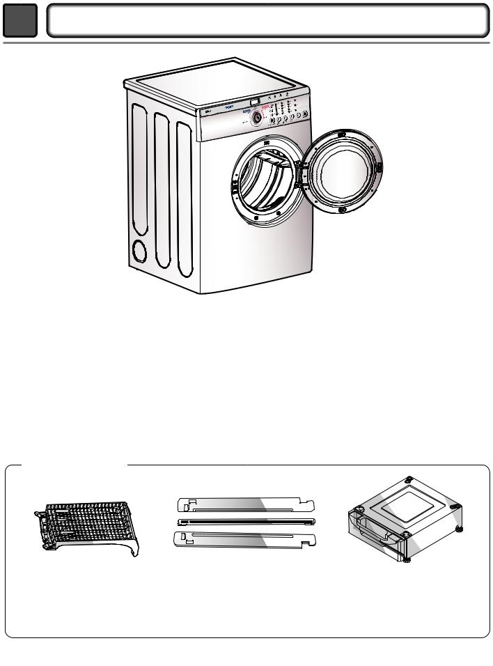
■ Name |
: Electric and Gas Dryer |
|||||||
■ Power supply |
: Please refer to the rating label regarding detailed |
|||||||
|
|
|
information. |
|||||
■ Size |
: 68.6 X 96.5 X 73.0 (cm) |
|||||||
■ Dryer capacity |
: IEC 7.0 cu.ft. |
|||||||
■ Weight |
: 126(Ibs) |
|||||||
Specifications are subject to change by manufacturer.
■ ACESSORIES
|
|
|
|
|
|
|
|
|
|
|
|
|
|
|
|
|
|
|
|
|
|
|
|
|
|
|
|
|
|
|
|
|
|
|
|
|
|
|
|
|
|
|
|
|
|
|
|
|
|
|
|
|
|
|
|
|
|
|
|
|
|
|
|
|
|
|
|
|
|
|
|
|
|
|
|
|
|
|
|
|
|
|
|
|
|
|
|
|
|
|
|
|
|
|
|
|
|
|
|
|
|
|
|
|
|
|
|
|
|
|
|
|
|
|
|
|
|
|
|
|
|
|
|
|
|
|
|
|
|
|
|
|
|
|
|
|
|
|
|
|
|
|
|
|
|
|
|
|
|
|
Dryer rack (1 each) |
|
|
|
|
|
|
Stacking kit (1 each) |
|
|
|
Pedestal (1 each) |
|
|
|
|
|
|
|
|
|
Purchased Separately |
|
|
|
Purchased Separately |
|
||
|
|
|
||||||||||||
|
|
|
|
|
|
|
|
|
|
|
|
|
|
|
|
|
|
|
|
|
|
|
|
|
|
|
|
|
|
See page 6 for how to use. |
|
|
|
|
|
|
|
See page 7 for how to use. |
See page 8 for how to use. |
|
||||
4

|
ITEM |
DLE2512W |
|
DLE2514W |
REMARK |
|||
|
DLG2522W |
|
DLG2524W |
|||||
|
|
|
|
|
|
|
||
|
|
|
|
|
|
|
|
|
|
|
|
|
Color |
Blue White |
|
|
|
Material & |
|
|
|
|
|
|
|
|
|
|
Top Plate |
Painted |
|
|
|||
Finishes |
|
|
|
|
||||
|
|
|
|
|
|
|
|
|
|
|
Door Trim |
Silver |
|
Blue White |
|
||
|
|
|
|
|
||||
POWER SUPPLY |
120V / 240V 60Hz (26A) |
|
||||||
|
|
|
|
|
|
|
|
|
ELECTRICITY |
|
MOTOR |
250W (4.5A) |
AC 120V |
||||
|
|
|
|
|
|
|||
|
HEATER |
5400W (22.5A) |
AC 240V (ELECTRIC TYPE) |
|||||
CONSUMPTION |
|
|||||||
|
|
|
|
|
|
|||
|
LAMP |
15 W (125mA) |
AC 120V |
|||||
|
|
|
|
|||||
|
|
|
|
|
|
|
||
|
|
|
|
GAS VALVE |
13 W (110mA) x 2 |
AC 120V(GAS TYPE) |
||
|
|
|
|
|
|
|
||
CONTROL TYPE |
Electronic |
|
|
|||||
|
|
|
|
|
|
|
||
DRUM CAPACITY |
7.0 cu.ft. |
|
|
|||||
|
|
|
|
|
||||
Weight (lbs) : Net / Gross |
124 / 144 |
|
|
|||||
|
|
|
|
|
||||
No. of Programs |
5 |
|
|
|||||
|
|
|
|
|
|
|
||
No. of Dry Options |
3 |
|
|
|||||
|
|
|
|
|
|
|
||
No. of Temperature Controls |
5 |
|
|
|||||
|
|
|
|
|
||||
No. of Dry Levels |
3 |
|
|
|||||
|
|
|
|
|||||
Sound levels |
High / Low / Off |
|
||||||
|
|
|
|
|
|
|
|
|
Sensor |
|
|
Moisture |
Avaiable |
|
Electrode sensor |
||
|
|
|
|
|
|
|
|
|
|
Temperature |
Avaiable |
|
Termistor |
||||
|
|
|
||||||
|
|
|
|
|
|
|||
Reversible Door |
Avaiable |
|
|
|||||
|
|
|
|
|
|
|
||
|
Drum |
|
|
Double Coated Steel |
|
|||
|
|
|
|
|
||||
Dryer Rack |
Avaiable |
|
|
|||||
|
|
|
|
|
||||
Child Lock |
Avaiable |
|
|
|||||
|
|
|
|
|
||||
Interior Light |
Avaiable |
|
|
|||||
|
|
|
|
|||||
Product (WxHxD) |
27" x 38.7" x 29.6" |
|
||||||
|
|
|
|
|||||
Packing (WxHxD) |
29 1/2" x 44 3/4 x 30 3/4 |
|
||||||
|
|
|
|
|
5 |
|
|
|

2 FEATURES AND BENEFITS
3 |
INSTALLATION INSTRUCTIONS |
Dryer Rack Installation Instructions
with both hands.
6
drum inside and door rim.
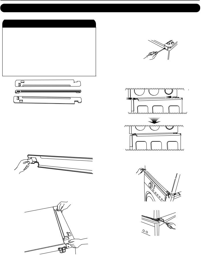
Stacking Kit Installation Instructions
• Do not use stacking kit with a gas dryer in potentially unstable conditions like a mobile
home.
7
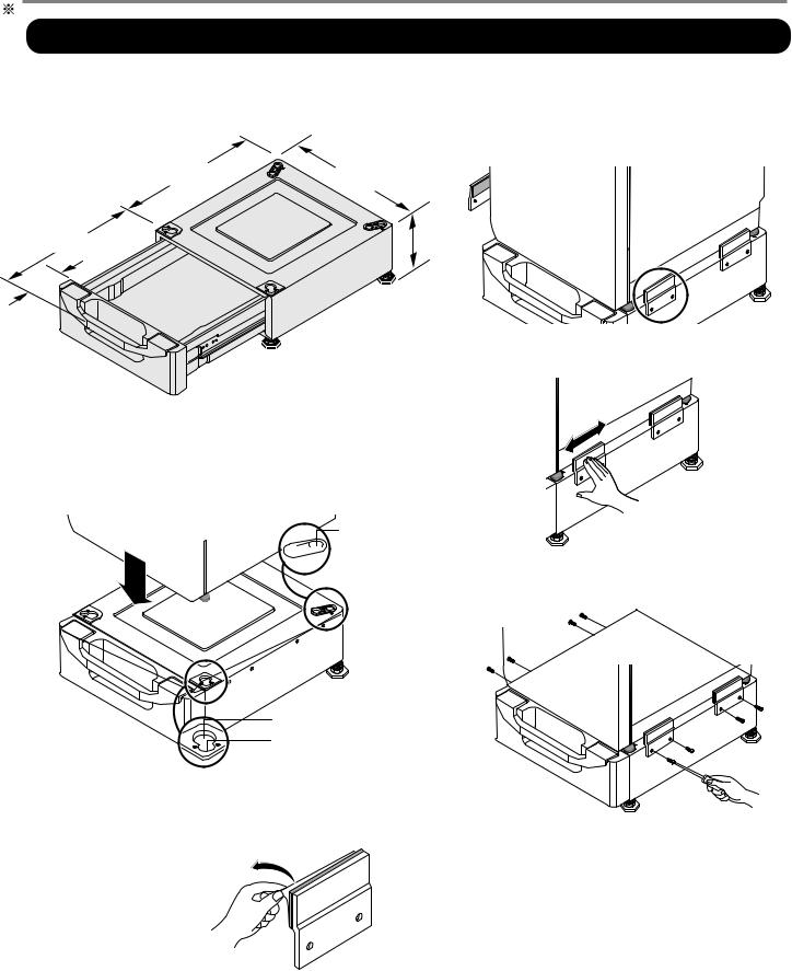
Pedestal Installation Instructions
4 Attach the double-faced tape of the bracket to the dryer as shown so the bent parts of the brackets align with the edge and can be attached to the pedestal with screws.
NOTE : Attach the lower side first.
5 Be sure to press the adhesive parts of the brackets firmly to the appliance.
1 Remove pedestal, installation hardware, and instructions from the shipping carton.
2 Position dryer on top of the pedestal.
,


 for washer/ combo
  for dryer
6 Install the eight (8) screws(supplied) to attach the brackets to the pedestal.
|
for dryer |
. |
for washer/ |
|
combo |
3 Remove the paper from the bracket.
7 Move the dryer to the desired place.
NOTE : The appliance and pedestal assembly must be placed on a solid and level floor for proper operation. Adjust the legs of the appliance and pedestal by turning with a wrench. Then, adjust the lock unt toward the pedestal while holding the pedestal leg using a wrench.
8
Review the following options to determine for your home:
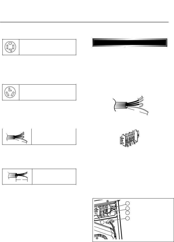
4-wire receptacle (NEMA type14-30R)
Use the instructions at this section if your home has a 4-wire receptacle (NEMA type 14-30R) and you will be using a UL listed, 120/240 volt minimum, 30 amp, dryer power supply cord.
3-wire receptacle (NEMA type10-30R)


 4-wire connection : Direct wire
Important : use 4-wire connection in the places such as mobile homes and areas where 3-wire connections is not available.
Prepare minimum 5ft(1.52m) of length in order for dryer to be replaced.
First, peel 5 inch (12.7cm) of covering material from end. Make a 5 inch of ground wire bared. After cutting 11/2 inch (3.8cm) from 3 other wires. peel insulation back 1inch (2.5cm). Make ends of 3 wires a hook
shape. |
1" |
cm) |
|
|
|
|
5 |
|
|
. |
|
|
(2 |
|
Use the instructions at this section if your home has a 3-wire receptacle (NEMA type 10-30R) and you will be using a UL listed, 120/240 volt minimum, 30 amp, dryer power supply cord.
5" |
|
31/2" |
|
(12.7 cm) |
|
(8.6 cm) |
|
|
|
|
|
1" |
cm) |
1" |
|
|
|
cm) |
|
5 |
.5 |
||
. |
|
|
|
(2 |
|
(2 |
|
4-wire direct
|
|
3V2" |
|
.7 |
cm) |
(8.9 |
cm) |
|
|||
|
|
||
|
|
|
|
.7 |
cm) |
|
Then, put the hooked shape end of the wire under the screw of the terminal block(hooked end facing rightward) and pinch the hook together and screw tightly.
If this type is available at your home. you will be connecting to a fused disconnect or circuit breaker box
|
3-wire direct |
|
5" |
31/ |
" |
|
2 |
|
(12.7 cm) |
(8.6 cm) |
|
If this type is available at your home. you will be connecting to a fused disconnect or circuit breaker box
1.Connect neutral wire(white) of power cord to center terminal block screw.
2.Connect red and black wire to the left and right terminal block screws.
3.Connect ground wire(green) of power cord to external ground screw and move neutral ground wire of appliance and connect it to center screw.
4.Make sure that the strain relief screw is tightened.
and be sure that all terminal block nuts are on tight and power cord is in right position.
d
 e
e


 f
f  c
c
b 
9


 3-wire connection : Direct wire
Important : use 3-wire connection in the places such as mobile homes and areas where 3-wire connections is not available.
Prepare minimum 5ft(1.52m) of length in order for dryer to be replaced.
First, peel 3 1/2 inch (8.9cm) of covering material from end and bare 1 inch from the ends.
1" |
|
.5 |
cm) |
|
|
(2 |
|
2" |
|
3V |
|
.9 cm) |
|
(8 |
|
Then, put the hooked shape end of the wire under the screw of the terminal block(hooked end facing rightward) and pinch the hook together and screw tightly. 
Option 1: 4-wire connection with a Power supply cord.
•lf your local codes or ordinances do not allow the use of a 3 wire connection, or you are installing your dryer in a mobile home, you must use a 4- wire connection.
1.Connect neutral wire(white) of power cord to center terminal block screw.
2.Connect red and black wire to the left and right terminal block screws.
3.Make sure that the strain relief screw is tightened and be sure that all terminal block nuts are on tight and power cord is in right position.
c |
b |
d |
e |
d
 e
e


 f
f
c
b
1.Connect neutral wire(white) of power cord to center terminal block screw.
2.Connect red and black wire to the left and right terminal block screws.
3.Connect ground wire(green) of power cord to external ground screw and move neutral ground wire of appliance and connect it to center screw.
4.Make sure that the strain relief screw is tightened. and be sure that all terminal block nuts are on
10 |
tight and power cord is in right position. |
|
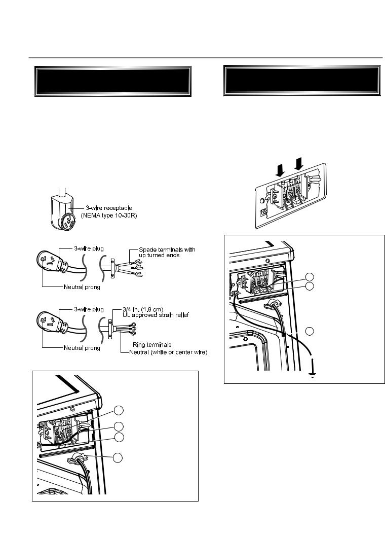
Option 2: 3-Wire Connection with a Power Supply Cord
lf your local codes or ordinances permit the connection of a frame-grounding conductor to the neutral wire, use these instructions. If your local codes or ordinances do not allow the connection of a frame-grounding conductor to the neutral wire, use the instructions under Section 3: Optional
3-wire connection.
Option 3: Optional 3-wire
connection.
•If your local codes or ordinances do not allow the connection of a frame-grounding conductor to the neutral wire, use the instructions under this section.
b c

 d
d
c |
b |
d |
e |
1.Connect neutral wire(white) of power cord to center terminal block screw.
2.Connect ground wire of appliance and neutral wire of power cord to center terminal block screw.
3.Connect red and black wire to the left and right terminal block screws.
4.Make sure that the strain relief screw is tightened. and be sure that all terminal block nuts are on tight and power cord is in right position.
5.Connect a independent ground wire from external
11 |
ground connector to proper ground. |
|
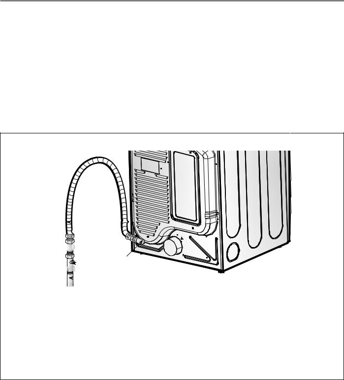
3-2. Connect Gas Supply Pipe (Gas Dryer ONLY)
For further assistance, refer to section on Gas Requirements.
1.Make certain your dryer is equipped for use with the type of gas in your laundry room. Dryer is equipped at the factory for Natural Gas with a 3/8” N.P.T. gas connection.
2.Remove the shipping cap from the gas connection at the rear of the dryer. Make sure you do not damage the pipe thread when removing the cap.
3.Connect to gas supply pipe using a new flexible stainless steel connector.
4.Tighten all connections securely. Turn on gas and check all pipe connections (internal & external) for gas leaks with a non-corrosive leak detection fluid.
5.For L.P. (Liquefied Petroleum) gas connection, refer to section on Gas Requirements.
 1
1


 2
2
5

 3
3  4
4
1 |
New Stainless Steel Flexible Connector - Use |
4 |
Black Iron Pipe |
|
only if allowed by local codes (Use Design |
|
Shorter than 20’ (6.1 m) - Use 3/8” pipe |
|
A.G.A. Certified Connector) |
|
Longer than 20’ (6.1 m) - Use 1/2” pipe |
2 |
1/8” N.P.T. Pipe Plug |
5 |
3/8” N.P.T. Gas Connection |
|
(for checking inlet gas pressure) |
|
|
3Equipment Shut-Off Valve-Installed within 6’ (1.8 m) of dryer
12
 Loading...